applied computational electromagnetics society journalcapolino.eng.uci.edu/publications_papers...
TRANSCRIPT
AppliedComputationalElectromagneticsSocietyJournal
Guest EditorDeb Chatterjee
November 2006Vol. 21 No. 3ISSN 1054-4887
Special Issue onPhased and Adaptive Array Antennas

GENERAL PURPOSE AND SCOPE: The Applied Computational Electromagnetics Society (ACES) Journal hereinafter known as the ACES Journal is devoted to the exchange of information in computational electromagnetics, to the advancement of the state-of-the art, and the promotion of related technical activities. A primary objective of the information exchange is the elimination of the need to “re-invent the wheel” to solve a previously-solved computational problem in electrical engineering, physics, or related fields of study. The technical activities promoted by this publication include code validation, performance analysis, and input/output standardization; code or technique optimization and error minimization; innovations in solution technique or in data input/output; identification of new applications for electromagnetics modeling codes and techniques; integration of computational electromagnetics techniques with new computer architectures; and correlation of computational parameters with physical mechanisms. SUBMISSIONS: The ACES Journal welcomes original, previously unpublished papers, relating to applied computational electromagnetics. Typical papers will represent the computational electromagnetics aspects of research in electrical engineering, physics, or related disciplines. However, papers which represent research in applied computational electromagnetics itself are equally acceptable. Manuscripts are to be submitted through the upload system of ACES web site http://aces.ee.olemiss.edu See “Information for Authors” on inside of back cover and at ACES web site. For additional information contact the Editor-in-Chief:
Dr. Atef Elsherbeni Department of Electrical Engineering The University of Mississippi University, MS 386377 USA Phone: 662-915-5382 Fax: 662-915-7231 Email: [email protected] SUBSCRIPTIONS: All members of the Applied Computational Electromagnetics Society who have paid their subscription fees are entitled to receive the ACES Journal with a minimum of three issues per calendar year and are entitled to download any published journal article available at http://aces.ee.olemiss.edu. Back issues, when available, are $15 each. Subscriptions to ACES are through the web site. Orders for back issues of the ACES Journal and changes of addresses should be sent directly to ACES Executive Officer: Dr. Richard W. Adler ECE Department, Code ECAB Naval Postgraduate School 833 Dyer Road, Room 437 Monterey, CA 93943-5121 USA Fax: 831-649-0300
Email: [email protected] Allow four week’s advance notice for change of address. Claims for missing issues will not be honored because of insufficient notice or address change or loss in mail unless the Executive Officer is notified within 60 days for USA and Canadian subscribers or 90 days for subscribers in other countries, from the last day of the month of publication. For information regarding reprints of individual papers or other materials, see “Information for Authors”. LIABILITY. Neither ACES, nor the ACES Journal editors, are responsible for any consequence of misinformation or claims, express or implied, in any published material in an ACES Journal issue. This also applies to advertising, for which only camera-ready copies are accepted. Authors are responsible for information contained in their papers. If any material submitted for publication includes material that has already been published elsewhere, it is the author’s responsibility to obtain written permission to reproduce such material.
APPLIED COMPUTATIONAL ELECTROMAGNETICS SOCIETY JOURNAL Special Issue on Phased and Adaptive Array Antennas
Guest Editor Deb Chatterjee November 2006 Vol. 21 No. 3 ISSN 1054-4887
The ACES Journal is abstracted in INSPEC, in Engineering Index, and in DTIC. The first, fourth, and sixth illustrations on the front cover have been obtained from the Department of Electrical Engineering at the University of Mississippi. The third and fifth illustrations on the front cover have been obtained from Lawrence Livermore National Laboratory. The second illustration on the front cover has been obtained from FLUX2D software, CEDRAT S.S. France, MAGSOFT Corporation, New York.

THE APPLIED COMPUTATIONAL ELECTROMAGNETICS SOCIETY http//:aces.ee.olemiss.edu
ACES JOURNAL EDITORS
EDITOR-IN-CHIEF/ACES/JOURNAL Atef Elsherbeni University of Mississippi, EE Dept. University, MS 38677, USA EDITORIAL ASSISTANT Matthew J. Inman University of Mississippi, EE Dept. University, MS 38677, USA EDITOR-IN-CHIEF, EMERITUS David E. Stein USAF Scientific Advisory Board Washington, DC 20330, USA
ASSOCIATE EDITOR-IN-CHIEF Alexander Yakovlev University of Mississippi, EE Dept. University, MS 38677, USA EDITOR-IN-CHIEF, EMERITUS Ducan C. Baker EE Dept. U. of Pretoria 0002 Pretoria, South Africa EDITOR-IN-CHIEF, EMERITUS Allen Glisson University of Mississippi, EE Dept. University, MS 38677, USA
MANAGING EDITOR Richard W. Adler 833 Dyer Rd, Rm 437 EC/AB NPS, Monterey, CA 93943-5121, USA EDITOR-IN-CHIEF, EMERITUS Robert M. Bevensee Box 812 Alamo, CA 94507-0516, USA EDITOR-IN-CHIEF, EMERITUS Ahmed Kishk University of Mississippi, EE Dept. University, MS 38677, USA
ACES JOURNAL ASSOCIATE EDITORS Giandomenico Amendola Universita' della Calabria Rende , Italy John Beggs NASA Langley Research Center Hampton, VA, USA Malcolm Bibby Gullwings Weston, MA , US John Brauer Ansoft Corporation Milwaukee, WI, USA Magda El-Shenawee University of Arkansas Fayetteville AR, USA Pat Foster Microwave & Antenna Systems Gt. Malvern, Worc. UK Cynthia M. Furse Utah State University Logan UT, USA Christian Hafner Swiss Federal Inst. of Technology Zurich, Switzerland Michael Hamid University of South Alabama, Mobile, AL, USA
Andy Harrison Radiance Technologies, Inc. Huntsville, AL Chun-Wen Paul Huang Anadigics, Inc. Warren, NJ, USA Todd H. Hubing University of Missouri-Rolla Rolla, MO, USA Nathan Ida The University of Akron Akron, OH, USA Yasushi Kanai Niigata Institute of Technology Kashiwazaki, Japan Leo C. Kempel Michigan State University East Lansing MI, USA Andrzej Krawczyk Institute of Electrical Engineering Warszawa, Poland Stanley Kubina Concordia University Montreal, Quebec, Canada Samir F. Mahmoud Kuwait University Safat, Kuwait
Ronald Marhefka Ohio State University Columbus, OH, USA Edmund K. Miller LASL Santa Fe, NM, USA Krishna Naishadham Wright State University Dayton, OH, USA Giuseppe Pelosi University of Florence Florence, Italy Vicente Rodriguez ETS-Lindgren Cedar Park, TX, USA Harold A. Sabbagh Sabbagh Associates Bloomington, IN, USA John B. Schneider Washington State University Pullman, WA, USA Amr M. Sharawee American University Cairo, Egypt Norio Takahashi Okayama University Tsushima, Japan
Guest Editorial
ACES Invited Special Issue on Phased and Adaptive Array Antennas
This invited special issue of the Applied Computational Electromagnetics Society (ACES) Journal on Phased and Adaptive Array Antennas aims to capture information on a broad spectrum of the various aspects involved in array radiating systems and their applications. Recent advances in this area can be found in [1]-[3]. The earlier special issue [4] on a closely similar topic served as a guide in preparing for this ACES special issue. The information gleaned from these sources resulted in a widening of the scope of this special issue than was originally planned. For enhanced impact, it appeared appropriate to solicit contributions from leading researchers in the antennas and computational electromagnetics (CEM) areas. To that end, in quite a few cases, the topic of the invited contribution was suggested to the individual authors. All invited papers were peer-reviewed per standard guidelines. In all there are twenty papers co-authored or authored by leading researchers from various countries. They represent a wide range of topics on phased and adaptive arrays. Specifically, papers on characteristic basis functions, genetic algorithms, ship-board arrays, conformal arrays, phased arrays for biomedical applications, multiple-beam phased arrays, array mutual coupling compensation, power-divider network, etc., appear here and provide useful information on both modeling and practical applications of phased and adaptive arrays. The valuable contribution of the authors and their patience is gratefully acknowledged. In the course of assembling the special issue, special thanks go to Prof. Atef Elsherbeni (editor-in-chief) and Prof. Alexander Yakovlev (associate editor-in-chief) of ACES Journal, University of Mississippi (Ole Miss). The encouragement from Dr. W. Ross-Stone, editor-in-chief, IEEE Antennas and Propagation Magazine, is deeply appreciated. It is a pleasure to acknowledge the extensive editorial help from Mr. Mohamed Al Sharkawy (Ole Miss), in the final stages. At University of Missouri Kansas City (UMKC), Mr. Naresh Vijaya Yalamanchili had painstakingly retyped some of the manuscripts for this invited special issue. Thanks to all of them for their continued encouragement and timely help. Without their active support this endeavor would not have come to fruition. The final judgment on the quality of this invited special issue rests on the reader. It is hoped that the reader shall find the contents in these papers of continuing value. Any drawback or other errors is the sole responsibility of the guest editor. References [1] Arun K. Bhattacharyya, Phased Array Antennas: Floquet Analysis, Synthesis, BFNs, and
Active Array Systems. Hoboken, NJ, USA: John-Wiley & Sons, Inc., 2006. [2] L. Josefsson and P. Persson, Conformal Array Antenna: Theory and Design. Hoboken,
NJ, USA: Wiley-Interscience, 2006. [3] L. C. Godara, Smart Antennas. Boca Raton, FL, USA: CRC Press, 2004. [4] R. J. Mailloux (ed.), Special Issue on Phased Arrays, IEEE Transactions on Antennas
and Propagation, vol. 47, no. 3, March 1999.

Deb Chatterjee is an associate professor of Electrical and Computer Engineering, with the Computer Science and Electrical Engineering (CSEE) Department at University of Missouri Kansas City (UMKC), where he joined as a faculty in August 1999. He obtained his M.A.Sc. and Ph.D. degrees in Electrical and Computer Engineering and Electrical Engineering, from Concordia University, Montreal, Canada and University of Kansas, Lawrence, Kansas, respectively. His current research interests are in phased arrays, high-frequency
scattering and propagation, miniature, ultra-wideband microstrip antennas. He has served as a reviewer of technical articles for IEEE Transactions on Antennas and Propagation, IEEE Antennas and Wireless Propagation Letters, Radio Science, and the Applied Computational Electromagnetics Society (ACES) Journal. Currently he serves as an associate editor for International Journal of Antennas and Propagation (IJAP). Dr. Chatterjee has published 35 articles in peer-reviewed journals and conference proceedings, and has taught courses in the area of electromagnetics and antennas at undergraduate and graduate levels. He is a member of the IEEE Antennas and Propagation and the Applied Computational Electromagnetics Societies.
THE APPLIED COMPUTATIONAL ELECTROMAGNETICS SOCIETY
JOURNAL
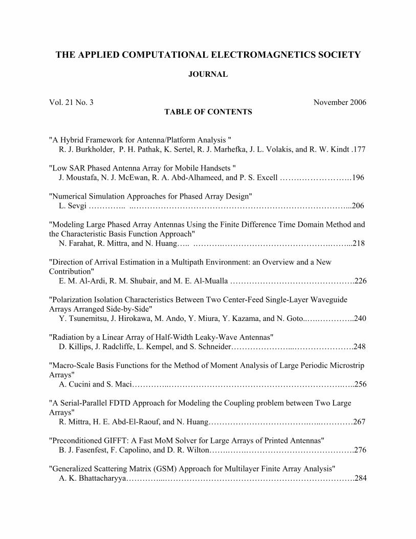
Vol. 21 No. 3 November 2006 TABLE OF CONTENTS
"A Hybrid Framework for Antenna/Platform Analysis "
R. J. Burkholder, P. H. Pathak, K. Sertel, R. J. Marhefka, J. L. Volakis, and R. W. Kindt .177
"Low SAR Phased Antenna Array for Mobile Handsets " J. Moustafa, N. J. McEwan, R. A. Abd-Alhameed, and P. S. Excell ……..……………...196
"Numerical Simulation Approaches for Phased Array Design" L. Sevgi ………….. ..……………………………………………………………………...206
"Modeling Large Phased Array Antennas Using the Finite Difference Time Domain Method and the Characteristic Basis Function Approach"
N. Farahat, R. Mittra, and N. Huang….. .……….………………………………….……...218 "Direction of Arrival Estimation in a Multipath Environment: an Overview and a New Contribution"
E. M. Al-Ardi, R. M. Shubair, and M. E. Al-Mualla ……………………………………….226 "Polarization Isolation Characteristics Between Two Center-Feed Single-Layer Waveguide Arrays Arranged Side-by-Side"
Y. Tsunemitsu, J. Hirokawa, M. Ando, Y. Miura, Y. Kazama, and N. Goto..….…………..240 "Radiation by a Linear Array of Half-Width Leaky-Wave Antennas"
D. Killips, J. Radcliffe, L. Kempel, and S. Schneider…………………...………………….248
"Macro-Scale Basis Functions for the Method of Moment Analysis of Large Periodic Microstrip Arrays"
A. Cucini and S. Maci…………..……………………………………………………….…..256
"A Serial-Parallel FDTD Approach for Modeling the Coupling problem between Two Large Arrays"
R. Mittra, H. E. Abd-El-Raouf, and N. Huang……………………………….…..…………267 "Preconditioned GIFFT: A Fast MoM Solver for Large Arrays of Printed Antennas"
B. J. Fasenfest, F. Capolino, and D. R. Wilton…….…….………………………………….276 "Generalized Scattering Matrix (GSM) Approach for Multilayer Finite Array Analysis"
A. K. Bhattacharyya…………...…………………………………………………………….284
"Modeling the RF Performance of a Small Array" P. R. Foster and A. E. Wicks…………………...……..…………………………………….291
"A Critical Examination of Receive and Transmit Scan Element Pattern for Phased Arrays"
R. C. Hansen……………………………………………..………………………………….299 “Modeling Conformal Array Antennas of Various Shapes Using Uniform Theory of Diffraction (UTD)"
P. Persson …………………………………………………………………………………...305 "Efficient Wideband Power Divider for Planar Antenna Arrays"
V. Demir, D. A. Elsherbeni, D. Kajfez, and A. Z. Elsherbeni ……………………………...318 "Genetic Algorithm Applications for Phased Arrays"
R. L. Haupt ………………………………………………………………………………..325 "Genetic Algorithm Optimization of a Traveling Wave Array of Longitudinal Slots in a Rectangular Waveguide"
A. Jensen and S. R. Rengarajan……………………………………………………………..337 "Approximate Compensation for Mutual Coupling in a Direct Data Domain Least Squares Approach using the In-situ Measured Element Patterns "
W. Choi, T. K. Sarkar, O. E. Allen, and J. S. Asvestas……………………………………..342 "Multiple Beam Antenna Technology for Satellite Communications Payloads"
S. Rao, M. Tang, and C. Hsu………………………………………………………………..353 "A Survey of Phased Arrays for Medical Applications"
C. Furse ………………………………………………………………………….………….365
© 2006, The Applied Computational Electromagnetics Society
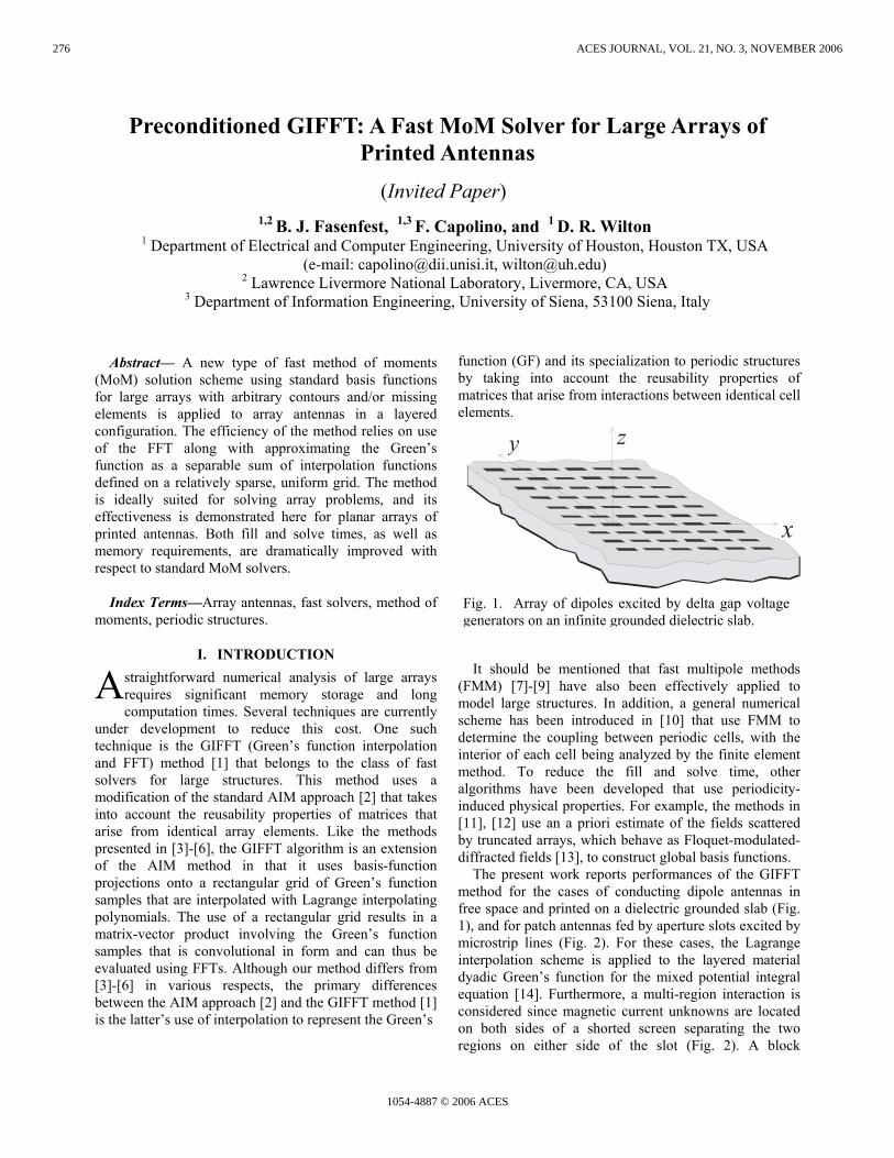
Abstract— A new type of fast method of moments (MoM) solution scheme using standard basis functions for large arrays with arbitrary contours and/or missing elements is applied to array antennas in a layered configuration. The efficiency of the method relies on use of the FFT along with approximating the Green’s function as a separable sum of interpolation functions defined on a relatively sparse, uniform grid. The method is ideally suited for solving array problems, and its effectiveness is demonstrated here for planar arrays of printed antennas. Both fill and solve times, as well as memory requirements, are dramatically improved with respect to standard MoM solvers.
Index Terms—Array antennas, fast solvers, method of moments, periodic structures.
I. INTRODUCTION straightforward numerical analysis of large arrays requires significant memory storage and long computation times. Several techniques are currently
under development to reduce this cost. One such technique is the GIFFT (Green’s function interpolation and FFT) method [1] that belongs to the class of fast solvers for large structures. This method uses a modification of the standard AIM approach [2] that takes into account the reusability properties of matrices that arise from identical array elements. Like the methods presented in [3]-[6], the GIFFT algorithm is an extension of the AIM method in that it uses basis-function projections onto a rectangular grid of Green’s function samples that are interpolated with Lagrange interpolating polynomials. The use of a rectangular grid results in a matrix-vector product involving the Green’s function samples that is convolutional in form and can thus be evaluated using FFTs. Although our method differs from [3]-[6] in various respects, the primary differences between the AIM approach [2] and the GIFFT method [1] is the latter’s use of interpolation to represent the Green’s
function (GF) and its specialization to periodic structures by taking into account the reusability properties of matrices that arise from interactions between identical cell elements.
It should be mentioned that fast multipole methods (FMM) [7]-[9] have also been effectively applied to model large structures. In addition, a general numerical scheme has been introduced in [10] that use FMM to determine the coupling between periodic cells, with the interior of each cell being analyzed by the finite element method. To reduce the fill and solve time, other algorithms have been developed that use periodicity-induced physical properties. For example, the methods in [11], [12] use an a priori estimate of the fields scattered by truncated arrays, which behave as Floquet-modulated-diffracted fields [13], to construct global basis functions.
The present work reports performances of the GIFFT method for the cases of conducting dipole antennas in free space and printed on a dielectric grounded slab (Fig. 1), and for patch antennas fed by aperture slots excited by microstrip lines (Fig. 2). For these cases, the Lagrange interpolation scheme is applied to the layered material dyadic Green’s function for the mixed potential integral equation [14]. Furthermore, a multi-region interaction is considered since magnetic current unknowns are located on both sides of a shorted screen separating the two regions on either side of the slot (Fig. 2). A block
1,2 B. J. Fasenfest, 1,3 F. Capolino, and 1 D. R. Wilton 1 Department of Electrical and Computer Engineering, University of Houston, Houston TX, USA
(e-mail: [email protected], [email protected]) 2 Lawrence Livermore National Laboratory, Livermore, CA, USA
3 Department of Information Engineering, University of Siena, 53100 Siena, Italy
Preconditioned GIFFT: A Fast MoM Solver for Large Arrays of Printed Antennas
A
x
y z
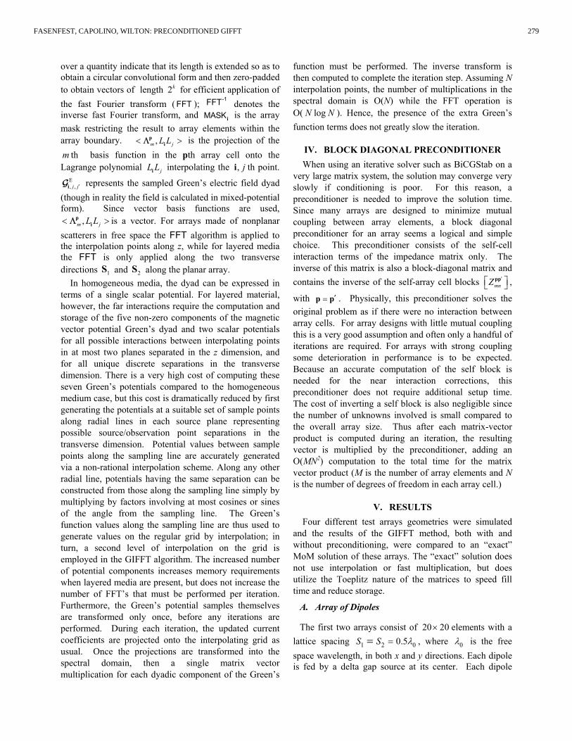
Fig. 1. Array of dipoles excited by delta gap voltage generators on an infinite grounded dielectric slab.
(Invited Paper)
276
1054-4887 © 2006 ACES
ACES JOURNAL, VOL. 21, NO. 3, NOVEMBER 2006
preconditioning scheme is implemented to greatly reduce the number of iterations required for a solution. If the array consists of planar conducting bodies, the array elements are meshed using standard subdomain basis functions for triangles [15]; the same bases may be used in the apertures where magnetic unknowns are defined. The GIFFT algorithm has been implemented in the standard method of moments (MoM) code EIGERTM [16]. In our implementation, the array boundaries are not restricted to be rectangular, and the array excitation can be arbitrary.
The method greatly reduces solution time by speeding up the computation of matrix-vector products needed in iterative solutions. The GIFFT approach also reduces fill time and memory requirements since the sparse interpolation can be used for all but near element interactions.
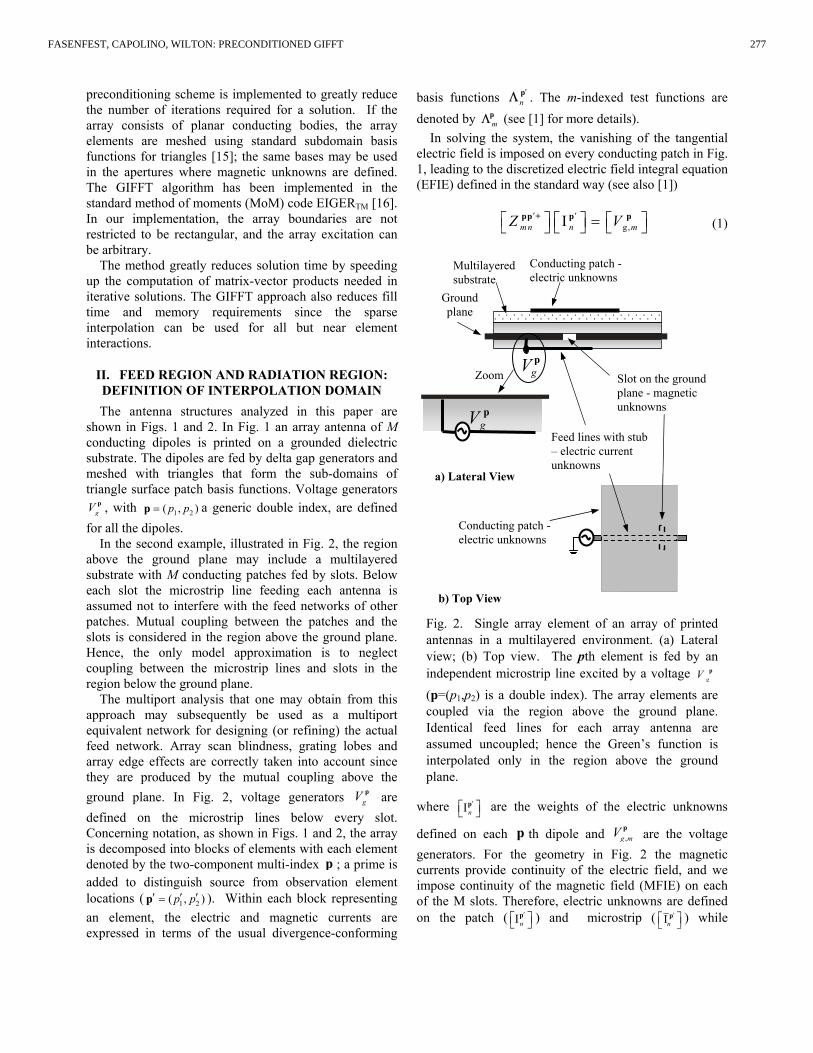
II. FEED REGION AND RADIATION REGION: DEFINITION OF INTERPOLATION DOMAIN The antenna structures analyzed in this paper are
shown in Figs. 1 and 2. In Fig. 1 an array antenna of M conducting dipoles is printed on a grounded dielectric substrate. The dipoles are fed by delta gap generators and meshed with triangles that form the sub-domains of triangle surface patch basis functions. Voltage generators
gV p , with 1 2( , )p p p= a generic double index, are defined for all the dipoles.
In the second example, illustrated in Fig. 2, the region above the ground plane may include a multilayered substrate with M conducting patches fed by slots. Below each slot the microstrip line feeding each antenna is assumed not to interfere with the feed networks of other patches. Mutual coupling between the patches and the slots is considered in the region above the ground plane. Hence, the only model approximation is to neglect coupling between the microstrip lines and slots in the region below the ground plane.
The multiport analysis that one may obtain from this approach may subsequently be used as a multiport equivalent network for designing (or refining) the actual feed network. Array scan blindness, grating lobes and array edge effects are correctly taken into account since they are produced by the mutual coupling above the ground plane. In Fig. 2, voltage generators gV p are defined on the microstrip lines below every slot. Concerning notation, as shown in Figs. 1 and 2, the array is decomposed into blocks of elements with each element denoted by the two-component multi-index p ; a prime is added to distinguish source from observation element locations ( 1 2( , )p p′ ′ ′=p ). Within each block representing an element, the electric and magnetic currents are expressed in terms of the usual divergence-conforming
basis functions pn
′Λ . The m-indexed test functions are denoted by p
mΛ (see [1] for more details). In solving the system, the vanishing of the tangential
electric field is imposed on every conducting patch in Fig. 1, leading to the discretized electric field integral equation (EFIE) defined in the standard way (see also [1])
g,pp + p pmn n mZ V′ ′ Ι = (1)
where p
n′ Ι are the weights of the electric unknowns
defined on each p th dipole and ,p
g mV are the voltage generators. For the geometry in Fig. 2 the magnetic currents provide continuity of the electric field, and we impose continuity of the magnetic field (MFIE) on each of the M slots. Therefore, electric unknowns are defined on the patch ( p
n′ Ι ) and microstrip ( p
n′ Ι ) while
Fig. 2. Single array element of an array of printed antennas in a multilayered environment. (a) Lateral view; (b) Top view. The pth element is fed by an independent microstrip line excited by a voltage gV p (p=(p1,p2) is a double index). The array elements are coupled via the region above the ground plane. Identical feed lines for each array antenna are assumed uncoupled; hence the Green’s function is interpolated only in the region above the ground plane.
b) Top View
pgV
Multilayered substrate
Zoom
Ground plane
pgV
a) Lateral View
Conducting patch - electric unknowns
Slot on the ground plane - magnetic unknowns
Feed lines with stub – electric current unknowns
Conducting patch - electric unknowns
277FASENFEST, CAPOLINO, WILTON: PRECONDITIONED GIFFT
magnetic unknowns pnV ′ are placed on the slots,
resulting in the system equation
, g,
0
0 0 0
0
0 0 0 0
0
0
nmn mn
n
mn mn n
n
mn mn n m
mn mn n
Z
Y V
Z V
Y V
β
β
δ β
β
′′ ′
′
′ ′ ′
′
′− −′
′
Ι − Ι
Ι + − Ι =
ppp + pp +
p
pp + pp + p
p
p pp p
- - p
.
0
(2) The + or – superscripts denote operators for regions
above or below the ground plane. The matrix ppmnZ ′ is the
EFIE operator connecting blocks p and p′ , and ppmnY ′ is its
dual, representing the magnetic field due to magnetic current sources; pp
mnβ ′ is the corresponding magnetic field integral equation (MFIE) operator. Subscripts m and n index testing and basis functions within cells p and ′p , respectively, and the matrix vector products in (1), (2) sum over the indices m
and ( )1 2,p p′ ′ ′p = . The corresponding matrices mnZ − , mnY − ,
and mnβ − that appear only on diagonal blocks represent the coupling to the structures below the ground plane for each array element; they affect only the p p′= self blocks because the Kronecker delta , 1p pδ ′ = for ′=p p , and
, 0p pδ ′ = for ′≠p p . Note that the number of blocks in the first matrix in (2) grows as the square of the number of array elements while the size of the second matrix remains the same for any number of array elements.
Using standard MoM, the matrix in (1) or the first matrix in (2) has huge memory, fill, and solve time requirements for large arrays. This computational difficulty arises from the top region because of the coupling between even widely separated array elements that in most situations cannot be neglected. The numerical burden is reduced by applying GIFFT to this region. That is, the Green’s function terms in this region are sampled and interpolated as shown below, and the matrix vector product for the majority of the system is accelerated by using the FFT.
III. THE GIFFT METHOD For simplicity we show the basic idea of the GIFFT
method only for the EFIE, i.e., the moment matrix-vector for the original discretized EFIE in (1). Analogous concepts apply to the other operators pp +
mn′β and pp +
mnY ′ involved in (2). Thus, (1) or the first block product from the left matrix of (2), is written as [1]
pp p pp p pp pmn n mn n mn nZ Z Z′ ′ ′ ′ ′ ′ Ι = ∆ Ι + Ι (3)
where mnZ ′pp denotes matrix elements approximated via the interpolation scheme. The interpolation, however, is inaccurate for nearby cells, which require the correction matrix mn mn mnZ Z Z′ ′ ′∆ = −pp pp pp . The correction matrix is a block Toeplitz difference matrix that may be taken as zero for elements whose indices satisfy 1 1 1p p c′− ≥ and
2 2 2p p c′− ≥ for some constants 1 2( , )c c ; hence it is sparse. Furthermore, it is constructed from a single computation on a stencil of cells consisting of an observation cell and adjacent cells. The m-indexed test functions are denoted by p
mΛ (see [1] for more details.) To evaluate the matrix/vector product, we note that
mn nZ ′ ′ ∆ Ι pp p is quickly computed since mnZ ′∆ pp is sparse,
whereas mn nZ ′ ′ Ι pp p is of convolutional form and can be
evaluated using a 2D FFT as follows [1]:
E, ,
1
, , '
,
,
mn n m j
N
j j j n nn
j j
Z L L
L L
′ ′
′ ′′ ′
′ =
Ι = < > ⋅
⋅ ⋅ < >Ι
∑
∑∑
pp p pi
p pi i i i i i
p
i
Λ
Λ-1MASK FFT FFT FFT G
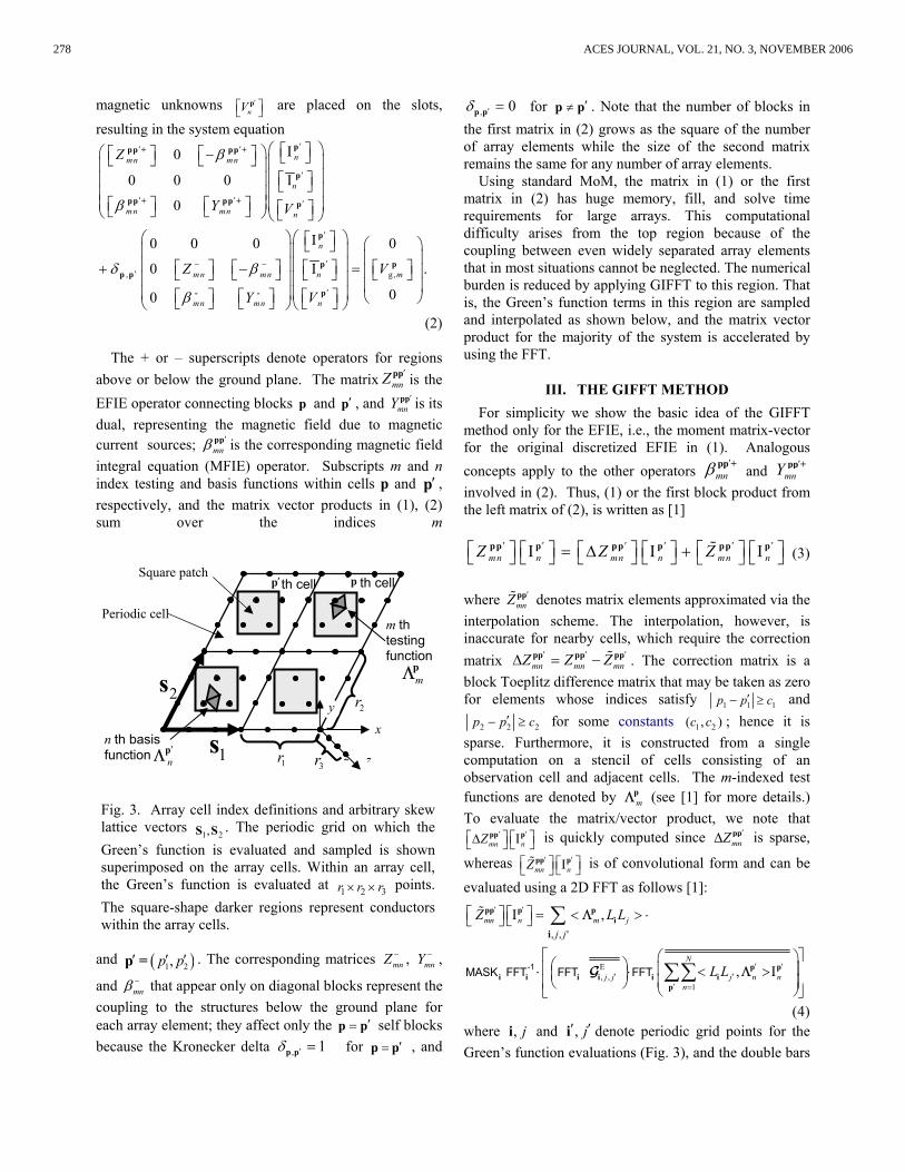
(4) where , ji and ,i j′ ′ denote periodic grid points for the Green’s function evaluations (Fig. 3), and the double bars
x
z1s
2s
th cell p′ p
1r 3r
2r
n th basis function n
′pΛ
m th testing function
mpΛ
z
th cell
Periodic cell
Square patch
y
Fig. 3. Array cell index definitions and arbitrary skew lattice vectors
1 2,S S . The periodic grid on which the Green’s function is evaluated and sampled is shown superimposed on the array cells. Within an array cell, the Green’s function is evaluated at 1 2 3r r r× × points. The square-shape darker regions represent conductors within the array cells.
278 ACES JOURNAL, VOL. 21, NO. 3, NOVEMBER 2006
over a quantity indicate that its length is extended so as to obtain a circular convolutional form and then zero-padded to obtain vectors of length 2k for efficient application of the fast Fourier transform ( FFT ); -1FFT denotes the inverse fast Fourier transform, and iMASK is the array mask restricting the result to array elements within the array boundary. ,m jL L< >p
iΛ is the projection of the m th basis function in the pth array cell onto the Lagrange polynomial jL Li interpolating the , ji th point.
E, ,j j ′iG represents the sampled Green’s electric field dyad
(though in reality the field is calculated in mixed-potential form). Since vector basis functions are used,
,m jL L< >piΛ is a vector. For arrays made of nonplanar
scatterers in free space the FFT algorithm is applied to the interpolation points along z, while for layered media the FFT is only applied along the two transverse directions 1S and 2S along the planar array.
In homogeneous media, the dyad can be expressed in terms of a single scalar potential. For layered material, however, the far interactions require the computation and storage of the five non-zero components of the magnetic vector potential Green’s dyad and two scalar potentials for all possible interactions between interpolating points in at most two planes separated in the z dimension, and for all unique discrete separations in the transverse dimension. There is a very high cost of computing these seven Green’s potentials compared to the homogeneous medium case, but this cost is dramatically reduced by first generating the potentials at a suitable set of sample points along radial lines in each source plane representing possible source/observation point separations in the transverse dimension. Potential values between sample points along the sampling line are accurately generated via a non-rational interpolation scheme. Along any other radial line, potentials having the same separation can be constructed from those along the sampling line simply by multiplying by factors involving at most cosines or sines of the angle from the sampling line. The Green’s function values along the sampling line are thus used to generate values on the regular grid by interpolation; in turn, a second level of interpolation on the grid is employed in the GIFFT algorithm. The increased number of potential components increases memory requirements when layered media are present, but does not increase the number of FFT’s that must be performed per iteration. Furthermore, the Green’s potential samples themselves are transformed only once, before any iterations are performed. During each iteration, the updated current coefficients are projected onto the interpolating grid as usual. Once the projections are transformed into the spectral domain, then a single matrix vector multiplication for each dyadic component of the Green’s
function must be performed. The inverse transform is then computed to complete the iteration step. Assuming N interpolation points, the number of multiplications in the spectral domain is O(N) while the FFT operation is O( logN N ). Hence, the presence of the extra Green’s function terms does not greatly slow the iteration.
IV. BLOCK DIAGONAL PRECONDITIONER When using an iterative solver such as BiCGStab on a
very large matrix system, the solution may converge very slowly if conditioning is poor. For this reason, a preconditioner is needed to improve the solution time. Since many arrays are designed to minimize mutual coupling between array elements, a block diagonal preconditioner for an array seems a logical and simple choice. This preconditioner consists of the self-cell interaction terms of the impedance matrix only. The inverse of this matrix is also a block-diagonal matrix and contains the inverse of the self-array cell blocks pp
mnZ ′ ,
with p p′= . Physically, this preconditioner solves the original problem as if there were no interaction between array cells. For array designs with little mutual coupling this is a very good assumption and often only a handful of iterations are required. For arrays with strong coupling some deterioration in performance is to be expected. Because an accurate computation of the self block is needed for the near interaction corrections, this preconditioner does not require additional setup time. The cost of inverting a self block is also negligible since the number of unknowns involved is small compared to the overall array size. Thus after each matrix-vector product is computed during an iteration, the resulting vector is multiplied by the preconditioner, adding an O(MN2) computation to the total time for the matrix vector product (M is the number of array elements and N is the number of degrees of freedom in each array cell.)
V. RESULTS Four different test arrays geometries were simulated
and the results of the GIFFT method, both with and without preconditioning, were compared to an “exact” MoM solution of these arrays. The “exact” solution does not use interpolation or fast multiplication, but does utilize the Toeplitz nature of the matrices to speed fill time and reduce storage.
A. Array of Dipoles
The first two arrays consist of 20 20× elements with a lattice spacing 1 2 00.5S S == λ , where 0λ is the free space wavelength, in both x and y directions. Each dipole is fed by a delta gap source at its center. Each dipole
279FASENFEST, CAPOLINO, WILTON: PRECONDITIONED GIFFT
contains 23 unknowns and is 00.39λ long and 00.01λ wide. In the first test case the dipoles are in free space, while in the second one the same dipoles are printed on a grounded dielectric slab as in Fig. 1. The height of the dielectric slab is 00.19d = λ and its relative permittivity
is 2.55rε = , as for the case treated in [17]. Both these cases used fourth order interpolation of the Green’s Function in both transverse directions. The GF is thus sampled at five points in each direction, resulting in
1 2 5 5 25r r× = × = points for each array cell. Interpolation points are also distributed along the border of an array cell and are thus shared by contiguous cells, so the computational burden is determined by the evaluation and storage of the various GF components for only 16 distinct points per array cell.
The third case analyzed consists of an array of 25 25× square conducting patches in free space illuminated by a plane wave at 6 GHz incident from a direction perpendicular to the array plane. The patches are 11.4 [mm] on a side with a separation of 3.8 [mm] between patches, and thus the lattice spacings are S1 = S2 =15.2 [mm]. Each patch was meshed using triangles, creating 65 unknowns per patch. This GIFFT method used fifth order (25 distinct points per cell) interpolating polynomials in both planar directions.
Table 1 shows the run times for the standard MoM and GIFFT solutions of the three arrays, as well as the error in the GIFFT solution compared to that of the standard MoM, which takes advantage of the Toeplitz storage that also reduces the fill time. It can be clearly seen that the GIFFT method offers a dramatic savings in both fill and solve times while maintaining a high level of accuracy that is evaluated as the average of the relative errors over all the unknowns. It can also be seen that use of the preconditioner dramatically reduces the number of
BiCGstab iterations needed for a solution, further reducing solution time. The BiCGstab iterations are stopped when the solution error determined by the algorithm is lower than 10-4. The GIFFT method also dramatically reduces the memory storage requirements. For example, for the 25 25× square patch array (M = 625 array cells), each patch was discretized using N=65 basis functions, requiring storage of N N× =4225 complex numbers for each ,p p′ block pp
mnZ ′ of the full impedance matrix. Instead, using GIFFT with a fifth order interpolation scheme, we need to store only 36 Green’s function samples per array cell. Interpolation points are also distributed along the border of an array cell and are thus shared by contiguous cells resulting in 25 distinct sampling points per array cell. GIFFT’s storage advantage is further amplified by the fact that if there are M = 625 array cells in a square array, there are M2 matrix blocks in the complete matrix, while there are only about 4M blocks of sampled Green’s function points. The factor four arises from extending the evaluation domain of the Green’s function to consider all possible interactions on the actual array as shown in [1, Fig. 3]. For the 25× 25 array, this means that the system matrix for a standard solution must contain about
92 2 1.65 10 N M× = × complex entries (that reduce to 62 (2 1) 5.28 10 N M× − = × when stored in the Toeplitz
format), while there are only 325 4 62.5 10M× × = × entries in the sampled Green’s
function array in free space. As explained in Sec. III, for layered media, the number of the GIFFT complex samples must be multiplied by seven, the number of unique dyadic and scalar potential terms used in the mixed potential formulation.
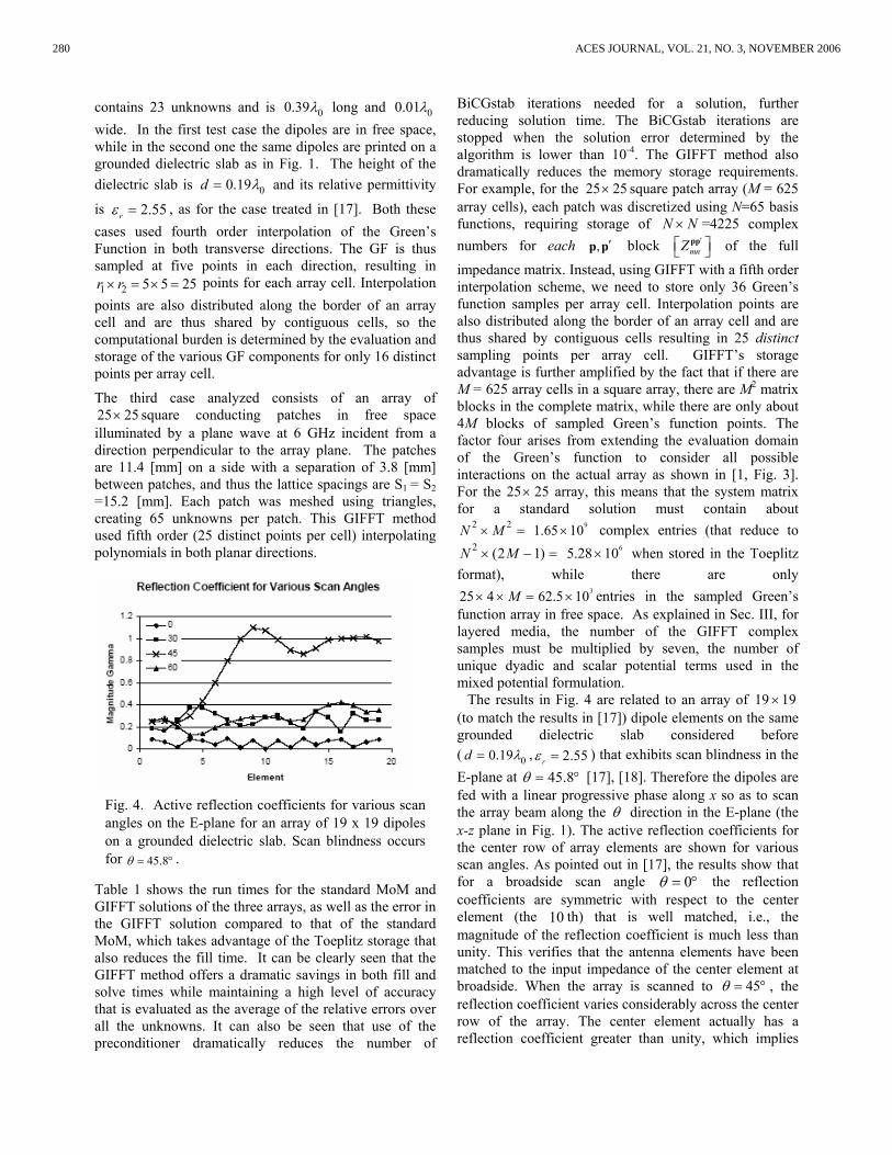
The results in Fig. 4 are related to an array of 19 19× (to match the results in [17]) dipole elements on the same grounded dielectric slab considered before ( 00.19d = λ , 2.55rε = ) that exhibits scan blindness in the E-plane at 45.8θ = ° [17], [18]. Therefore the dipoles are fed with a linear progressive phase along x so as to scan the array beam along the θ direction in the E-plane (the x-z plane in Fig. 1). The active reflection coefficients for the center row of array elements are shown for various scan angles. As pointed out in [17], the results show that for a broadside scan angle 0= °θ the reflection coefficients are symmetric with respect to the center element (the 10 th) that is well matched, i.e., the magnitude of the reflection coefficient is much less than unity. This verifies that the antenna elements have been matched to the input impedance of the center element at broadside. When the array is scanned to 45θ = ° , the reflection coefficient varies considerably across the center row of the array. The center element actually has a reflection coefficient greater than unity, which implies
Fig. 4. Active reflection coefficients for various scan angles on the E-plane for an array of 19 x 19 dipoles on a grounded dielectric slab. Scan blindness occurs for 45.8= °θ .
280 ACES JOURNAL, VOL. 21, NO. 3, NOVEMBER 2006
that it absorbs power from some of the other elements. In other words, the left-hand dipoles in Fig. 4 radiate power, some of which is delivered to the right-hand array elements through the strongly-excited guided wave on the structure.For this particular scan angle, most of the elements are not matched, showing the scan blindness effect, yet a few near the array edges still have relatively low reflection coefficients. These results for the reflection coefficient show very good agreement with previously published results for this array [17, Fig. 4].
B. Array of Patch Antennas Excited by Slots The final case considered is an array of elements that
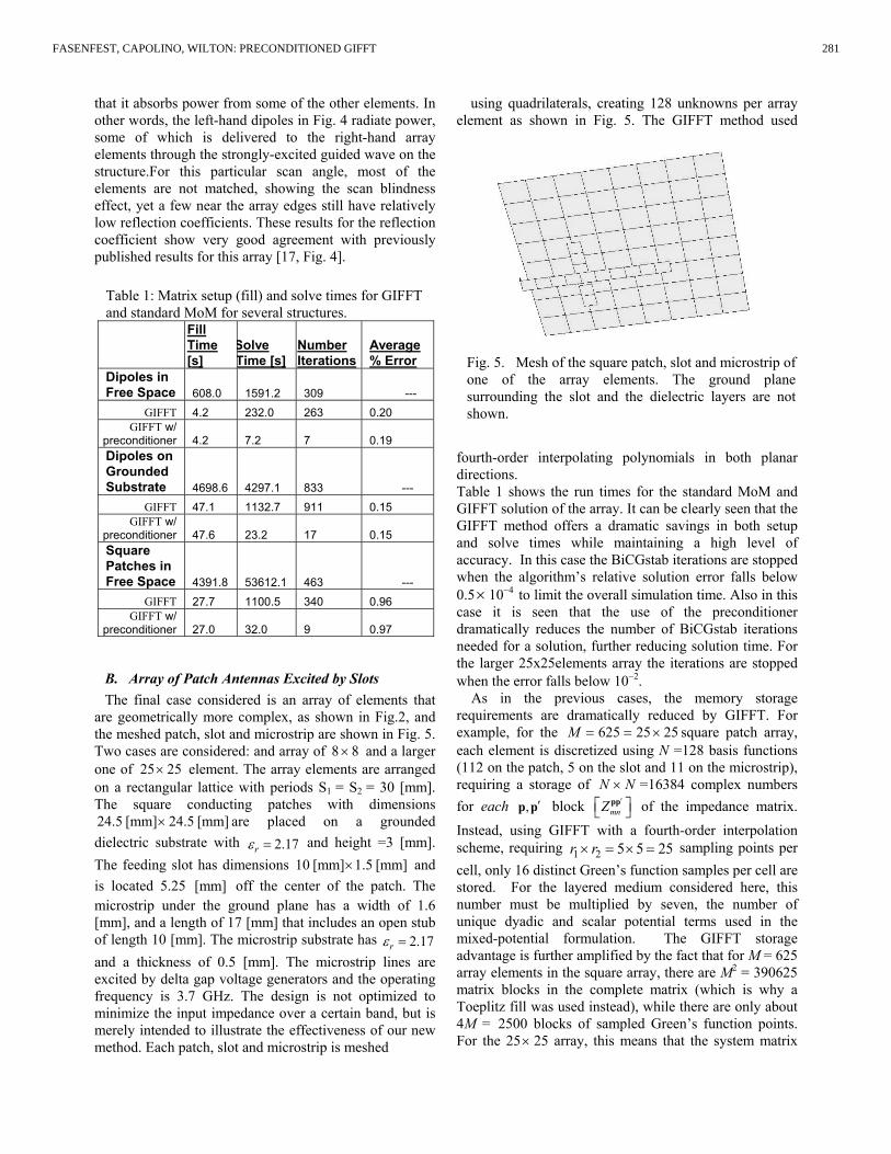
are geometrically more complex, as shown in Fig.2, and the meshed patch, slot and microstrip are shown in Fig. 5. Two cases are considered: and array of 8 8× and a larger one of 25 25× element. The array elements are arranged on a rectangular lattice with periods S1 = S2 = 30 [mm]. The square conducting patches with dimensions 24.5 [mm] 24.5 [mm]× are placed on a grounded dielectric substrate with 2.17rε = and height =3 [mm]. The feeding slot has dimensions 10 [mm] 1.5 [mm]× and is located 5.25 [mm] off the center of the patch. The microstrip under the ground plane has a width of 1.6 [mm], and a length of 17 [mm] that includes an open stub of length 10 [mm]. The microstrip substrate has 2.17rε = and a thickness of 0.5 [mm]. The microstrip lines are excited by delta gap voltage generators and the operating frequency is 3.7 GHz. The design is not optimized to minimize the input impedance over a certain band, but is merely intended to illustrate the effectiveness of our new method. Each patch, slot and microstrip is meshed
using quadrilaterals, creating 128 unknowns per array element as shown in Fig. 5. The GIFFT method used
fourth-order interpolating polynomials in both planar directions. Table 1 shows the run times for the standard MoM and GIFFT solution of the array. It can be clearly seen that the GIFFT method offers a dramatic savings in both setup and solve times while maintaining a high level of accuracy. In this case the BiCGstab iterations are stopped when the algorithm’s relative solution error falls below 0.5 × 10⁻⁴ to limit the overall simulation time. Also in this case it is seen that the use of the preconditioner dramatically reduces the number of BiCGstab iterations needed for a solution, further reducing solution time. For the larger 25x25elements array the iterations are stopped when the error falls below 10−2.
As in the previous cases, the memory storage requirements are dramatically reduced by GIFFT. For example, for the 625 25 25M = = × square patch array, each element is discretized using N =128 basis functions (112 on the patch, 5 on the slot and 11 on the microstrip), requiring a storage of N N× =16384 complex numbers for each ,p p′ block pp
mnZ ′ of the impedance matrix. Instead, using GIFFT with a fourth-order interpolation scheme, requiring 1 2 5 5 25r r× = × = sampling points per cell, only 16 distinct Green’s function samples per cell are stored. For the layered medium considered here, this number must be multiplied by seven, the number of unique dyadic and scalar potential terms used in the mixed-potential formulation. The GIFFT storage advantage is further amplified by the fact that for M = 625 array elements in the square array, there are M2 = 390625 matrix blocks in the complete matrix (which is why a Toeplitz fill was used instead), while there are only about 4M = 2500 blocks of sampled Green’s function points. For the 25× 25 array, this means that the system matrix
Table 1: Matrix setup (fill) and solve times for GIFFT and standard MoM for several structures.
Fill Time [s]
Solve Time [s]
Number Iterations
Average % Error
Dipoles in Free Space 608.0 1591.2 309 ---
GIFFT 4.2 232.0 263 0.20 GIFFT w/
preconditioner 4.2 7.2 7 0.19 Dipoles on Grounded Substrate 4698.6 4297.1 833 ---
GIFFT 47.1 1132.7 911 0.15 GIFFT w/
preconditioner 47.6 23.2 17 0.15 Square Patches in Free Space 4391.8 53612.1 463 ---
GIFFT 27.7 1100.5 340 0.96 GIFFT w/
preconditioner 27.0 32.0 9 0.97
Fig. 5. Mesh of the square patch, slot and microstrip of one of the array elements. The ground plane surrounding the slot and the dielectric layers are not shown.
281FASENFEST, CAPOLINO, WILTON: PRECONDITIONED GIFFT
for a standard MoM must contain about 2117 117 M× × 216 16 5.3 10 M× × = ×+ complex
entries; this reduces to 117 117 (2 1)M× × −
16 16 M× ×+ 617.1 10 = × when stored in the Toeplitz format. By contrast, there are only
37 16 4 280 10M× × × = × entries in the sampled Green’s function array in addition to those relative to the self blocks and difference matrix (see (2)) that also grow as M.
VI. CONCLUSION The GIFFT method for solving large array problems
[1] is extended here to arbitrary arrays of printed elements in a layered material with the possible slot feeds. A block diagonal preconditioner has been tested and found to greatly improve the solution time by reducing the number of iterations required by the BiCGstab solver. The examples presented show the advantages of the method in reducing the memory requirements of the MoM matrix, as well as in reducing setup and solution times. A multiport analysis of such arrays can thus be performed in reasonable time even for large array structures. An extension of the GIFFT algorithm for arrays of cavity-backed patch antennas is currently under progress.
REFERENCES [1] B. J. Fasenfest, F. Capolino, D. R. Wilton, D.R.
Jackson, and N. Champagne, “A fast MoM solution for large arrays: Green’s function interpolation with
FFT,” IEEE Antennas and Wireless Propagation Letters, Vol. 3, pp. 161-164, 2004.
[2] E. Bleszynski, M. Bleszynski, and T. Jaroszewicz, “AIM: Adaptive integral method for solving large scale electromagnetic scattering and radiation problems,” Radio Sci., Vol. 31, No. 5, pp. 1225-1251, 1996.
[3] S-Q Li, Y. Yu, C. H. Chan, K. F. Chan, and L. Tsang, “A sparse-matrix/canonical grid method for analyzing densely packed Interconnects,” IEEE Trans. Microwave Theory Tech., Vol. 49, No. 7, pp. 1221-1228, July 2001.
[4] L. Tsang; C. H. Chan, P. Kyung, and H. Sangani, “Monte-Carlo simulations of large-scale problems of random rough surface scattering and applications to grazing incidence with the BMIA/canonical grid method,” IEEE Trans. Antennas Propagat.,, Vol. 43, No. 8, Aug. 1995.
[5] S. M. Seo, and J. F. Lee, “A fast IE-FFT algorithm for solving PEC scattering problems,” IEEE Trans. on Magnetics, Vol. 41, No. 5, pp. 1476 – 1479, May 2005.
[6] A. Mori, F. De Vita, and A. Freni, “A modification of the canonical grid series expansion in order to increase the efficiency of the SMCG method,” IEEE Geoscience and Remote Sensing Letters, Vol. 2, No. 1, pp. 87-89 Jan. 2005.
[7] R. Coifman, V. Rokhlin, and S. Wandzura, “The fast multipole method for the wave equation: A pedestrian prescription,” IEEE Antennas Propagat. Mag., Vol. 35, No. 3, pp. 7-12, June 1993.
[8] W. C. Chew, J.-M. Jin, C.-C. Lu, E. Michielssen, and J. M. Song, “Fast solution methods in electromagnetics,” IEEE Trans. Antennas Propagat., Vol. 45, No. 3, pp. 533 – 543, March 1997.
[9] J. Song, C.-C. Lu, and W. C. Chew, “Multilevel fast multipole algorithm for electromagnetic scattering by large complex objects”, IEEE Trans. Antennas Propagat., Vol. 45, No. 10, pp. 1488 – 1493, Oct. 1997.
[10] R. W. Kindt and J. L. Volakis, “Array decomposition-fast multipole method for finite array analysis,” Radio Sci., Vol. 39, RS2018, 2004.
[11] A. Neto, S. Maci, G. Vecchi, and M. Sabbadini, “Truncated Floquet wave diffraction method for the full wave analysis of large phased arrays. Part I and II,” IEEE Trans. Antennas Propagat., Vol. 48, No. 4, pp. 594-611, April 2000.
[12] O. A. Civi, P.H. Pathak, H-T. Chou, and P. Nepa, “A hybrid uniform geometrical theory of diffraction-moment method for efficient analysis of electromagnetic radiation/scattering from large finite planar arrays,” Radio Science, Vol. 32, No. 2, pp. 607-620, March-April, 2000.
[13] F. Capolino, M. Albani, S. Maci, and L. B. Felsen, “Frequency-domain Green's function for a planar
Table 2: Matrix setup (fill) and solve times for GIFFT and standard MoM. Array of patches with slots and microstrip lines (Fig.2)
Setup Time
[s]
Solve Time [s]
Number Iterations
Average % Error
Array 8x8 MoM
w/ Toeplitz fill w/o precond. 1797 12551 2373 ---
GIFFT w/o precond. 240 4627 2473
0.55
GIFFT w/ precond. 240 36 19
0.55
Array 25x25
MoM w/ Toeplitz fill
w/ precond. ≈ 9 hr
≈ 11 min per sing
BiCGstab iteration
>100 program stopped before end
---
GIFFT w/ precond.
≈ 25 min
≈ 4 min (14s per iteration) 17
282 ACES JOURNAL, VOL. 21, NO. 3, NOVEMBER 2006
periodic semi-infinite phased array. Part I and II,” IEEE Trans. Antennas and Prop., Vol. 48, No. 1, pp. 67 – 85, Jan. 2000.
[14] K. A. Michalski, and D. Zheng, “Electromagnetic scattering and radiation by surfaces of arbitrary shape in layered media. I. Theory,” IEEE Trans. Antennas Propagat., Vol. 38, No. 3, pp. 335-344, March 1990.
[16] S. M. Rao, D. R. Wilton, and A. W. Glisson, “Electromagnetic scattering by surfaces of arbitrary shape,” IEEE Transactions on Antennas and Propagation, Vol. AP-30, No. 3, pp. 409-418, May 1982.
[17] W. A. Johnson, R. E. Jorgenson, L. K. Warne, J. D. Kotulski, J. B. Grant, R. M. Sharpe, N. J. Champagne, D. R. Wilton, and D.J. Jackson, “Our experiences with object-oriented design, FORTRAN 90, and massively parallel computations,” 1998 Digest USNC/URSI National Radio Science Meeting, p. 308, June 21-26, Atlanta, GA, 1998.
[18] D. M. Pozar, “Analysis of finite phased arrays of printed dipoles,” IEEE Trans. Antennas Propagat., Vol. 33, No. 10, pp. 1045-1053, Oct. 1985.
[19] D. M. Pozar, and D. H. Schaubert, “Analysis of an infinite array of rectangular microstrip patches with idealized probe feeds,” IEEE Trans. Antennas Propagat., Vol. 32, No. 10, pp. 1101-1107, Oct. 1984.
Bejamin. J. Fasenfest was born in Sacramento, CA, in 1980. He received the B.S. (summa cum laude) from the University of Houston in 2002, where an undergraduate research fellowship funded his research of dielectric resonator antennas. He was awarded a Tau Beta Pi fellowship, and continued on to a M.S. at the University of Houston in 2004, with a thesis on fast methods for large arrays. From 2004 to the present, he has worked at Lawrence Livermore National Laboratory, where his research interests include computational electromagnetics and electromagnetics modeling, from statics to terahertz.
Filippo Capolino was born in Florence, Italy, in 1967. He received the Laurea degree (cum laude) in electronic engineering and the Ph.D. degree, from the University of Florence, Italy, in 1993 and 1997, respectively. He has been a Research Associate until 2002 at the Dept. of
Information Engineering, University of Siena, Italy, where he is presently an Assistant Professor. From 1997 to 1998, he was a Fulbright Research Visitor with the Dept. of Aerospace and Mech. Engineering, Boston University, MA, where he continued his research with a
Grant from the Italian National Research Council (CNR), from 1998 to 1999. From 2000 to 2001 he was Research Assistant Visiting Professor with the Department of Electrical and Comp. Engineering, University of Houston, TX, where he is now an Adjunct Assistant Professor. In Nov.-Dec- 2003 he was an Invited Assistant Professor at the Institut Fresnel, France. His primary research interests include array antennas, periodic structures, numerical modeling, and metamaterials. He is the coordinator of the Siena Unit for the Network of Excellence “Metamorphose” on Metamaterials of the EU sixth framework program. Dr. Capolino was awarded with a MMET’94 Student Paper Competition Award in 1994, the Raj Mittra Travel Grant for Young and Senior Scientists in 1996, and 2006, respectively, the “Barzilai” prize for the best paper at the National Italian Congress of Electromagnetism (XI RiNEm) in 1996, and a Young Scientist Award for participating at the URSI Int. Symp. Electromagn. Theory in 1998. He received the R.W. P. King Prize Paper Award from the IEEE Antennas and Propagation Society for the Best Paper of the Year 2000, by an author under 36. He is an Associate Editor for the IEEE Transactions on Antennas and Propagation.
Donald R. Wilton was born in Lawton, OK, October 25, 1942. He received the B.S., M.S., and Ph.D. degrees from the University of Illinois, Urbana-Champaign, in 1964, 1966, and 1970, respectively. From 1965 to 1968 he was with Hughes Aircraft Co., Fullerton, CA, engaged in the analysis and design of
phased array antennas. From 1970–1983 he was with the Department of Electrical Engineering, University of Mississippi, and since 1983 he has been Professor of Electrical Engineering at the University of Houston. From 1978–1979 he was a Visiting Professor at Syracuse University. During 2004-2005 he was a visiting professor at the Polytechnic of Turin, Italy, the Sandia National Laboratories, and the University of Washington. His primary research interest is in computational electromagnetics, and he has published, lectured, and consulted extensively in this area. Dr. Wilton is a Fellow of the IEEE and received the IEEE Third Millenium Medal. He has served the IEEE Antennas and Propagation Society as an Associate Editor of the Transactions on Antennas and Propagation, as a Distinguished National Lecturer, and as a member of AdCom. Dr. Wilton is also a member of Commission B of URSI, in which he has held various offices including Chair of U. S. Commission B.
283FASENFEST, CAPOLINO, WILTON: PRECONDITIONED GIFFT


2006 INSTITUTIONAL MEMBERS
AUSTRALIAN DEFENCE LIBRARY Northcott Drive Campbell, A.C.T. 2600 AUSTRALIA BEIJING BOOK COMPANY, INC 701 E Lindon Ave. Linden, NJ 07036-2495 BRITISH LIBRARY Boston SPA, Wetherby West Yorkshire, UK LS23 7BQ DARMSTADT U. OF TECHNOLOGY Schlossgartenstrasse 8 Darmstadt, Hessen GERMANY D-64289 DARTMOUTH COLL-FELDBERG LIB 6193 Murdough Center Hanover, NH 03755-3560 DEFENCE RESEARCH ESTAB. LIB. 3701 Carling Avenue Ottowa, ON, K1A 0Z4 CANADA DLR-STANDORTBIBLIOTEK Muenchnerstrasse 20 Wessling, Germany 82234 DPS/LIBRARY (EABV) Alion Science & Technology 185 Admiral Cochrane Drive Annapolis, MD 214017307 DSTO-DSTORL EDINBURGH Jets AU/33851-99, PO Box 562 Milsons Point, NSW AUSTRALIA 1565 DTIC-OCP/LIBRARY 8725 John J. Kingman Rd. Ste 0944 Ft. Belvoir, VA 22060-6218 ELLEDIEMME SRL Via Baccina 30 Roma, Italy 00184 ELSEVIER Bibliographic Databases PO Box 2227 Amsterdam, Netherlands 1000 CE ENGINEERING INFORMATION, INC PO Box 543 Amsterdam, Netherlands 1000 Am
ETSE TELECOMUNICACION Biblioteca, Campus Lagoas Vigo, 36200 SPAIN FGAN-FHR Neuenahrerstrasse 20 Wachtberg, Germany 53343 FLORIDA INTERNATIONAL UNIV. ECE Dept./EAS-3983 10555 W. Flagler St Miami, FL 33174 GEORGIA TECH LIBRARY 225 North Avenue, NW Atlanta, GA 30332-0001 HRL LABS, RESEARCH LIBRARY 3011 Malibu Canyon Malibu, CA 90265 IEE INSPEC/Acquisitions Section Michael Faraday House 6 Hills Way Stevenage, Herts UK SG1 2AY IND CANTABRIA PO Box 830470 Birmingham, AL 35283 INSTITUTE FOR SCIENTIFIC INFO. Publication Processing Dept. 3501 Market St. Philadelphia, PA 19104-3302 LIBRARY of CONGRESS Reg. Of Copyrights Attn: 40T Deposits Washington DC, 20559 LINDA HALL LIBRARY 5109 Cherry Street Kansas City, MO 64110-2498 MISSISSIPPI STATE UNIV LIBRARY PO Box 9570 Mississippi State, MS 39762 MIT LINCOLN LABORATORY Periodicals Library 244 Wood Street Lexington, MA 02420 NA KANSAI KINOKUNNA CO. Attn: M. MIYOSHI PO Box 36 (NDLA KANSAI) Hongo, Tokyo, JAPAN 113-8688
NATL. CTR. FOR HIGH-PERFORMANCE COMPUTING LIB. PO Box 117-00930 Taipei City, Taiwan (ROC) 10699 NATL. GROUND INTELL. CENTER 2055 Boulders Road Charlottesville, VA 22911-8318 NAVAL POSTGRADUATE SCHOOL Attn:J. Rozdal/411 Dyer Rd./ Rm 111 Monterey, CA 93943-5101 NAVAL RESEARCH LABORATORY C. Office, 4555 Overlook Avenue, SW Washington, DC 20375 OHIO STATE UNIVERSITY 1320 Kinnear Road Columbus, OH 43212 OVIEDO LIBRARY PO BOX 830679 Birmingham, AL 35283 PAIKNAM ACAD. INFO CTR LIB. Hanyang U/17 Haengdang-Dong Seongdong-ki, Seoul, S Korea 133-791 PENN STATE UNIVERSITY 126 Paterno Library University Park, PA 16802-1808 PHILIPS RESEARCH LAB Cross Oak Lane, Stella Cox, Salfords Red Hill, UK RH1 5HA RENTON TECH LIBRARY/BOEING PO BOX 3707 SEATTLE, WA 98124-2207 SOUTHWEST RESEARCH INST. 6220 Culebra Road San Antonio, TX 78238 SWEDISH DEFENCE RES. AGENCY (FOI) PO Box 1165 Linkoping, Sweden S-58111 SWETS INFORMATION SERVICES 160 Ninth Avenue, Suite A Runnemede, NJ 08078

SYRACUSE UNIVERSITY EECS, 121 Link Hall Syracuse, NY 13244 TECHNISCHE UNIV. DELFT Mekelweg 4, Delft, Holland, 2628 CD NETHERLANDS TIB & UNIV. BIB. HANNOVER DE/5100/G1/0001 Welfengarten 1B Hannover, GERMANY 30167
TOKYO KOKA UNIVERSITY 1404-1 Katakura-Cho Hachioji, Tokyo, JAPAN 192-0914 UNIV OF CENTRAL FLORIDA LIB. 4000 Central Florida Boulevard Orlando, FL 32816-8005 UNIV OF COLORADO LIBRARY Campus Box 184 Boulder, CO 80309-0184
UNIVERSITY OF MISSISSIPPI John Davis Williams Library PO Box 1848 University, MS 38677-1848 UNIV OF MISSOURI-ROLLA LIB. 1870 Miner Circle Rolla, MO 65409-0001 USAE ENG. RES. & DEV. CENTER Attn: Library/Journals 72 Lyme Road Hanover, NH 03755-1290 USP POLI Av: Elmira Martins Moreira, 455 Jacarei, Sao Paulo, Brazil 12306-730

ACES COPYRIGHT FORM
This form is intended for original, previously unpublished manuscripts submitted to ACES periodicals and conference publications. The signed form, appropriately completed, MUST ACCOMPANY any paper in order to be published by ACES. PLEASE READ REVERSE SIDE OF THIS FORM FOR FURTHER DETAILS. TITLE OF PAPER: RETURN FORM TO:
Dr. Atef Z. Elsherbeni University of Mississippi Dept. of Electrical Engineering
AUTHORS(S) Anderson Hall Box 13 PUBLICATION TITLE/DATE: University, MS 38677 USA
PART A - COPYRIGHT TRANSFER FORM (NOTE: Company or other forms may not be substituted for this form. U.S. Government employees whose work is not subject to copyright may so certify by signing Part B below. Authors whose work is subject to Crown Copyright may sign Part C overleaf). The undersigned, desiring to publish the above paper in a publication of ACES, hereby transfer their copyrights in the above paper to The Applied Computational Electromagnetics Society (ACES). The undersigned hereby represents and warrants that the paper is original and that he/she is the author of the paper or otherwise has the power and authority to make and execute this assignment. Returned Rights: In return for these rights, ACES hereby grants to the above authors, and the employers for whom the work was performed, royalty-free permission to:
1. Retain all proprietary rights other than copyright, such as patent rights. 2. Reuse all or portions of the above paper in other works. 3. Reproduce, or have reproduced, the above paper for the author’s personal use or for internal company use provided that (a) the source and
ACES copyright are indicated, (b) the copies are not used in a way that implies ACES endorsement of a product or service of an employer, and (c) the copies per se are not offered for sale.
4. Make limited distribution of all or portions of the above paper prior to publication. 5. In the case of work performed under U.S. Government contract, ACES grants the U.S. Government royalty-free permission to reproduce all
or portions of the above paper, and to authorize others to do so, for U.S. Government purposes only. ACES Obligations: In exercising its rights under copyright, ACES will make all reasonable efforts to act in the interests of the authors and employers as well as in its own interest. In particular, ACES REQUIRES that: 1. The consent of the first-named author be sought as a condition in granting re-publication permission to others. 2. The consent of the undersigned employer be obtained as a condition in granting permission to others to reuse all or portions of the paper for promotion or marketing purposes. In the event the above paper is not accepted and published by ACES or is withdrawn by the author(s) before acceptance by ACES, this agreement becomes null and void. AUTHORIZED SIGNATURE TITLE (IF NOT AUTHOR) EMPLOYER FOR WHOM WORK WAS PERFORMED DATE FORM SIGNED
Part B - U.S. GOVERNMENT EMPLOYEE CERTIFICATION
(NOTE: if your work was performed under Government contract but you are not a Government employee, sign transfer form above and see item 5 under Returned Rights). This certifies that all authors of the above paper are employees of the U.S. Government and performed this work as part of their employment and that the paper is therefor not subject to U.S. copyright protection.
AUTHORIZED SIGNATURE TITLE (IF NOT AUTHOR) NAME OF GOVERNMENT ORGANIZATION DATE FORM SIGNED

PART C - CROWN COPYRIGHT
(NOTE: ACES recognizes and will honor Crown Copyright as it does U.S. Copyright. It is understood that, in asserting Crown Copyright, ACES in no way diminishes its rights as publisher. Sign only if ALL authors are subject to Crown Copyright). This certifies that all authors of the above Paper are subject to Crown Copyright. (Appropriate documentation and instructions regarding form of Crown Copyright notice may be attached). AUTHORIZED SIGNATURE TITLE OF SIGNEE NAME OF GOVERNMENT BRANCH DATE FORM SIGNED
Information to Authors
ACES POLICY ACES distributes its technical publications throughout the world, and it may be necessary to translate and abstract its publications, and articles contained therein, for inclusion in various compendiums and similar publications, etc. When an article is submitted for publication by ACES, acceptance of the article implies that ACES has the rights to do all of the things it normally does with such an article. In connection with its publishing activities, it is the policy of ACES to own the copyrights in its technical publications, and to the contributions contained therein, in order to protect the interests of ACES, its authors and their employers, and at the same time to facilitate the appropriate re-use of this material by others. The new United States copyright law requires that the transfer of copyrights in each contribution from the author to ACES be confirmed in writing. It is therefore necessary that you execute either Part A-Copyright Transfer Form or Part B-U.S. Government Employee Certification or Part C-Crown Copyright on this sheet and return it to the Managing Editor (or person who supplied this sheet) as promptly as possible. CLEARANCE OF PAPERS ACES must of necessity assume that materials presented at its meetings or submitted to its publications is properly available for general dissemination to the audiences these activities are organized to serve. It is the responsibility of the authors, not ACES, to determine whether disclosure of their material requires the prior consent of other parties and if so, to obtain it. Furthermore, ACES must assume that, if an author uses within his/her article previously published and/or copyrighted material that permission has been obtained for such use and that any required credit lines, copyright notices, etc. are duly noted. AUTHOR/COMPANY RIGHTS If you are employed and you prepared your paper as a part of your job, the rights to your paper initially rest with your employer. In that case, when you sign the copyright form, we assume you are authorized to do so by your employer and that your employer has consented to all of the terms and conditions of this form. If not, it should be signed by someone so authorized.
NOTE RE RETURNED RIGHTS: Just as ACES now requires a signed copyright transfer form in order to do “business as usual”, it is the intent of this form to return rights to the author and employer so that they too may do “business as usual”. If further clarification is required, please contact: The Managing Editor, R. W. Adler, Naval Postgraduate School, Code EC/AB, Monterey, CA, 93943, USA (408)656-2352. Please note that, although authors are permitted to re-use all or portions of their ACES copyrighted material in other works, this does not include granting third party requests for reprinting, republishing, or other types of re-use. JOINT AUTHORSHIP For jointly authored papers, only one signature is required, but we assume all authors have been advised and have consented to the terms of this form. U.S. GOVERNMENT EMPLOYEES Authors who are U.S. Government employees are not required to sign the Copyright Transfer Form (Part A), but any co-authors outside the Government are. Part B of the form is to be used instead of Part A only if all authors are U.S. Government employees and prepared the paper as part of their job.
NOTE RE GOVERNMENT CONTRACT WORK: Authors whose work was performed under a U.S. Government contract but who are not Government employees are required so sign Part A-Copyright Transfer Form. However, item 5 of the form returns reproduction rights to the U. S. Government when required, even though ACES copyright policy is in effect with respect to the reuse of material by the general public. January 2002

APPLIED COMPUTATIONAL ELECTROMAGNETICS SOCIETY JOURNAL http://aces.ee.olemiss.edu
INFORMATION FOR AUTHORS
PUBLICATION CRITERIA Each paper is required to manifest some relation to applied computational electromagnetics. Papers may address general issues in applied computational electromagnetics, or they may focus on specific applications, techniques, codes, or computational issues. While the following list is not exhaustive, each paper will generally relate to at least one of these areas: 1. Code validation. This is done using internal checks or
experimental, analytical or other computational data. Measured data of potential utility to code validation efforts will also be considered for publication.
2. Code performance analysis. This usually involves
identification of numerical accuracy or other limitations, solution convergence, numerical and physical modeling error, and parameter tradeoffs. However, it is also permissible to address issues such as ease-of-use, set-up time, run time, special outputs, or other special features.
3. Computational studies of basic physics. This involves
using a code, algorithm, or computational technique to simulate reality in such a way that better, or new physical insight or understanding, is achieved.
4. New computational techniques, or new applications for
existing computational techniques or codes. 5. “Tricks of the trade” in selecting and applying codes
and techniques. 6. New codes, algorithms, code enhancement, and code
fixes. This category is self-explanatory, but includes significant changes to existing codes, such as applicability extensions, algorithm optimization, problem correction, limitation removal, or other performance improvement. Note: Code (or algorithm) capability descriptions are not acceptable, unless they contain sufficient technical material to justify consideration.
7. Code input/output issues. This normally involves
innovations in input (such as input geometry standardization, automatic mesh generation, or computer-aided design) or in output (whether it be tabular, graphical, statistical, Fourier-transformed, or otherwise signal-processed). Material dealing with input/output database management, output interpretation, or other input/output issues will also be considered for publication.
8. Computer hardware issues. This is the category for
analysis of hardware capabilities and limitations of various types of electromagnetics computational requirements. Vector and parallel computational techniques and implementation are of particular interest.
Applications of interest include, but are not limited to, antennas (and their electromagnetic environments), networks, static fields, radar cross section, shielding, radiation hazards, biological effects, electromagnetic pulse (EMP), electromagnetic interference (EMI), electromagnetic compatibility (EMC), power transmission, charge transport, dielectric, magnetic and nonlinear materials, microwave components, MEMS technology, MMIC technology, remote sensing and geometrical and physical optics, radar and communications systems, fiber optics, plasmas, particle accelerators, generators and motors, electromagnetic wave propagation, non-destructive evaluation, eddy currents, and inverse scattering. Techniques of interest include frequency-domain and time-domain techniques, integral equation and differential equation techniques, diffraction theories, physical optics, moment methods, finite differences and finite element techniques, modal expansions, perturbation methods, and hybrid methods. This list is not exhaustive. A unique feature of the Journal is the publication of unsuccessful efforts in applied computational electromagnetics. Publication of such material provides a means to discuss problem areas in electromagnetic modeling. Material representing an unsuccessful application or negative results in computational electromgnetics will be considered for publication only if a reasonable expectation of success (and a reasonable effort) are reflected. Moreover, such material must represent a problem area of potential interest to the ACES membership. Where possible and appropriate, authors are required to provide statements of quantitative accuracy for measured and/or computed data. This issue is discussed in “Accuracy & Publication: Requiring, quantitative accuracy statements to accompany data,” by E. K. Miller, ACES Newsletter, Vol. 9, No. 3, pp. 23-29, 1994, ISBN 1056-9170. EDITORIAL REVIEW In order to ensure an appropriate level of quality control, papers are peer reviewed. They are reviewed both for technical correctness and for adherence to the listed guidelines regarding information content. JOURNAL CAMERA-READY SUBMISSION DATES March issue deadline 8 January July issue deadline 20 May November issue deadline 20 September Uploading an acceptable camera-ready article after the deadlines will result in a delay in publishing this article.

STYLE FOR CAMERA-READY COPY The ACES Journal is flexible, within reason, in regard to style. However, certain requirements are in effect: 1. The paper title should NOT be placed on a separate page.
The title, author(s), abstract, and (space permitting) beginning of the paper itself should all be on the first page. The title, author(s), and author affiliations should be centered (center-justified) on the first page.
2. An abstract is REQUIRED. The abstract should be a
brief summary of the work described in the paper. It should state the computer codes, computational techniques, and applications discussed in the paper (as applicable) and should otherwise be usable by technical abstracting and indexing services.
3. Either British English or American English spellings
may be used, provided that each word is spelled consistently throughout the paper.
4. Any commonly-accepted format for referencing is
permitted, provided that internal consistency of format is maintained. As a guideline for authors who have no other preference, we recommend that references be given by author(s) name and year in the body of the paper (with alphabetical listing of all references at the end of the paper). Titles of Journals, monographs, and similar publications should be in italic font or should be underlined. Titles of papers or articles should be in quotation marks.
5. Internal consistency shall also be maintained for other
elements of style, such as equation numbering. As a guideline for authors who have no other preference, we suggest that equation numbers be placed in parentheses at the right column margin.
6. The intent and meaning of all text must be clear. For
authors who are NOT masters of the English language, the ACES Editorial Staff will provide assistance with grammar (subject to clarity of intent and meaning).
7. Unused space should be minimized. Sections and
subsections should not normally begin on a new page. PAPER FORMAT The preferred format for initial submission and camera-ready manuscripts is 12 point Times Roman font, single line spacing and double column format, similar to that used here, with top, bottom, left, and right 1 inch margins. Manuscripts should be prepared on standard 8.5x11 inch paper. Only camera-ready electronic files are accepted for publication. The term “camera-ready” means that the material is neat, legible, and reproducible. Full details can be found on ACES site, Journal section. ACES reserves the right to edit any uploaded material, however, this is not generally done. It is the author(s)
responsibility to provide acceptable camera-ready pdf files. Incompatible or incomplete pdf files will not be processed, and authors will be requested to re-upload a revised acceptable version. SUBMITTAL PROCEDURE All submissions should be uploaded to ACES server through ACES web site (http://aces.ee.olemiss.edu) by using the upload button, journal section. Only pdf files are accepted for submission. The file size should not be larger than 5MB, otherwise permission from the Editor-in-Chief should be obtained first. The Editor-in-Chief will acknowledge the electronic submission after the upload process is successfully completed. COPYRIGHTS AND RELEASES Each primary author must sign a copyright form and obtain a release from his/her organization vesting the copyright with ACES. Copyright forms are available at ACES, web site (http://aces.ee.olemiss.edu). To shorten the review process time, the executed copyright form should be forwarded to the Editor-in-Chief immediately after the completion of the upload (electronic submission) process. Both the author and his/her organization are allowed to use the copyrighted material freely for their own private purposes. Permission is granted to quote short passages and reproduce figures and tables from and ACES Journal issue provided the source is cited. Copies of ACES Journal articles may be made in accordance with usage permitted by Sections 107 or 108 of the U.S. Copyright Law. This consent does not extend to other kinds of copying, such as for general distribution, for advertising or promotional purposes, for creating new collective works, or for resale. The reproduction of multiple copies and the use of articles or extracts for commercial purposes require the consent of the author and specific permission from ACES. Institutional members are allowed to copy any ACES Journal issue for their internal distribution only. PUBLICATION CHARGES ACES members are allowed 12 printed pages per paper without charge; non-members are allowed 8 printed pages per paper without charge. Mandatory page charges of $75 a page apply to all pages in excess of 12 for members or 8 for non-members. Voluntary page charges are requested for the free (12 or 8) pages, but are NOT mandatory or required for publication. A priority courtesy guideline, which favors members, applies to paper backlogs. Authors are entitled to 15 free reprints of their articles and must request these from the Managing Editor. Additional reprints are available to authors, and reprints available to non-authors, for a nominal fee. ACES Journal is abstracted in INSPEC, in Engineering Index, and in DTIC.