cisco lean retail sap erp application deployment · pdf filesap overview this section ... with...
TRANSCRIPT
Cisco Lean Retail SAP ERP Application Deployment Guide
Cisco Validated Design
July 19, 2008
IntroductionThe Cisco Lean Retail SAP ERP solution provides best practices and implementation guidance that optimizes application availability, performance, and security while lowering application ownership costs. Cisco's Lean Retail Architecture provides accelerated application performance and improved access to information. Data center-based applications and hosted managed services can have their performance accelerated to LAN-like speeds. SAP's core business application, Enterprise Resource Planning (ERP), is a business suite that helps retailers manage their inventory, supplier relationships and customer relationships.
Cisco's Lean Retail Architecture includes:
• Application and collaboration services
• Integrated networking services
• Reference network designs
A key Lean Retail integrated network service is the Application Networking Service (ANS). This solution focuses on the ANS components of Cisco Application Control Engine (Cisco ACE) and Wide Area Application Services (WAAS) product families. It provides data center, retail store, and remote end user application optimization services. This collaboration between SAP and Cisco addresses the following SAP Business Suite and NetWeaver deployment challenges:
• Reduced capital and operational costs for applications, servers, and networking
• Recovery time objectives (RTO) and recovery point objectives (RPO) for business continuity
• Application response time over limited WAN connections
• Application, server, network, and service-oriented architecture (SOA) security
The value of the Cisco Lean Retail is accomplished through four key benefits:
Corporate Headquarters:
Copyright © 2008 Cisco Systems, Inc. All rights reserved.
Cisco Systems, Inc., 170 West Tasman Drive, San Jose, CA 95134-1706 USA
Overview
• Application Availability—When an application server fails in a store only that store is impacted. When an application fails in a data center, many stores are impacted. A core tenet of Cisco's Lean Retail Architecture is the centralization of application services. Through server virtualization and load balancing, greater application uptime is achieved. Virtualized server resources in the data center leverage clustering and load balancing to share and distribute load across a larger pool of resources. A single failure does not impact overall accessibility of the application users.
• Performance Improvement—Traditionally, retailers use low bandwidth links. Many retailers have hundreds to thousands of stores. The incremental addition of WAN bandwidth per store significantly increases OPEX costs due to economies of scale. Retailers get more for less through the use of virtualized servers, load balancing and WAAS. Performance is significantly improved for the end user (both in stores and across the web). Servers are more fully utilized when loads are balanced across larger clusters. WAN performance is improved by locally caching content and accelerating the TCP protocol.
• Increased Security—Retailers need to comply with industry and regulatory requirements (e.g., PCI, HIPPA, and SOX), to avoid fines and penalties. Security features including encryption, segmentation and authentication address many of these requirements. The Cisco ACE applies stateful inspection rules that explicitly allow or deny specified traffic patterns. The Cisco ACE also uses role based access control to give independent access to both security and load-balancing policies. The Cisco ACE XML Gateway provides a full Layer-7 proxy and includes integrated XML security for web services transactions.
• Lowering Application ownership costs—Many retailers have hundreds to thousands of stores. Typically they have several servers in each store. For both existing and new applications, the incremental costs per store are significant. By removing servers from the stores, retailers are able to reduce OPEX costs on average of 16%1.
Deploying new applications and capabilities quickly and effectively are key IT metrics that improve an organization’s business agility. The Cisco Lean Retail enables more applications to be deployed centrally, cutting down significantly on the time and cost of deployment. Deploying centrally also reduces the costs of opening new stores and of integrating acquisitions. While many Retailers will choose to deploy some applications in the stores, the Cisco Lean Retail improves the capabilities of a central deployment model. To learn more about the Cisco Lean Retail Architecture, refer to: http://www.cisco.com/web/strategy/retail/lean-retail.html
OverviewRetailers look at optimization solutions whenever there is an imminent change ahead-such as a software upgrade-or when a new application is coming on line. It might be a new portal deployment that requires load-balancing or a security policy requiring end-to-end Secure Socket Layer (SSL) support. The WAN is often the biggest consideration when applications change, as bandwidth availability is so limited when dealing with retail's with issues of scale. Changing from an SAPGUI interface to a web browser, for example, can increase bandwidth usage ten-fold. To understand the kinds of changes and upgrades taking place within SAP deployments, it is helpful to understand the SAP application environment and how it has grown over the years. The following section describes the evolution of SAP software, both the business suite and the NetWeaver middleware which supports it.
1. Gartner: Server consolidation can save money 12/2005
2Cisco Lean Retail SAP ERP Application Deployment Guide
OL-16516-01
SAP Overview
SAP OverviewThis section summarizes the SAP application environment. It describes this software architecture in the following sections:
• SAP Business Suite, page 3
• Pre-NetWeaver—Standalone Middleware Applications, page 3
• NetWeaver 2004—Integration Platform, page 4
• NetWeaver 7.0/NetWeaver 2004s—Composition Platform, page 4
• NetWeaver 7.1—Business Process Platform, page 5
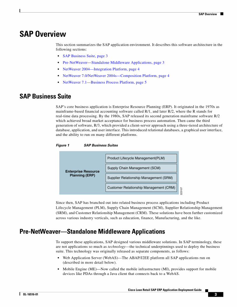
SAP Business SuiteSAP’s core business application is Enterprise Resource Planning (ERP). It originated in the 1970s as mainframe-based financial accounting software called R/1, and later R/2, where the R stands for real-time data processing. By the 1980s, SAP released its second generation mainframe software R/2 which achieved broad market acceptance for business process automation. Then came the third generation of software, R/3, which provided a client-server approach using a three-tiered architecture of database, application, and user interface. This introduced relational databases, a graphical user interface, and the ability to run on many different platforms.
Figure 1 SAP Business Suites
Since then, SAP has branched out into related business process applications including Product Lifecycle Management (PLM), Supply Chain Management (SCM), Supplier Relationship Management (SRM), and Customer Relationship Management (CRM). These solutions have been further customized across various industry verticals, such as education, finance, Manufacturing, and the like.
Pre-NetWeaver—Standalone Middleware ApplicationsTo support these applications, SAP designed various middleware solutions. In SAP terminology, these are not applications so much as technology—the technical underpinnings used to deploy the business suite. This technology was originally released as separate components, as follows:
• Web Application Server (WebAS)—The ABAP/J2EE platform all SAP applications run on (described in more detail below).
• Mobile Engine (ME)—Now called the mobile infrastructure (MI), provides support for mobile devices like PDAs through a Java client that connects back to a WebAS.
Enterprise ResourcePlanning (ERP)
Product Lifecycle Management(PLM)
Supply Chain Management (SCM)
Supplier Relationship Management (SRM)
Customer Relationship Management (CRM)
2231
07
3Cisco Lean Retail SAP ERP Application Deployment Guide
OL-16516-01
SAP Overview
• Enterprise Portal (EP)—Integrates access to multiple applications and customizes the view based on a user’s identity.
• Business Intelligence (BI)—A tool for advanced data analysis and reporting; also known as the business information warehouse (BW).
• Exchange Infrastructure (XI)—Enables cross-system processes between different applications, such as SAP, non-SAP, ABAP-based, Java-based, and the like. This was later renamed Process Integration (PI) toward the end of 2007.
NetWeaver 2004—Integration PlatformThe first release of NetWeaver is referred to as the Integration Platform because it brings together the multiple middleware programs under the NetWeaver umbrella. Each of the middleware applications listed above had its own release cycle and interdependencies creating a cost of ownership issue. To improve this SAP took all of the above components (WebAS, ME, EP, BI, and XI) and integrated them into NetWeaver 2004. This package also introduced new technology including:
• Knowledge Management (KM)—A framework in EP for document sharing, rating, and updating.
• Master Data Management (MDM)—A solution for consolidating and harmonizing data from multiple systems.
• Composite Application Framework—Applications built by combining multiple existing functions into a new application using web services. This is the first tool for building composites.
Note Each of these functions—while integrated into NetWeaver 2004—is still a standalone application. There might be an entire farm of servers just for BI, for example.
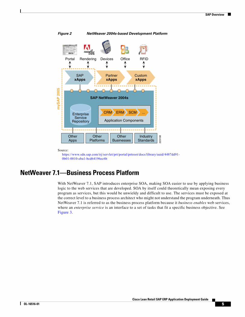
NetWeaver 7.0/NetWeaver 2004s—Composition PlatformOriginally called NetWeaver 2004s, NetWeaver 7.0 provides some updates to the various middleware components described above, but is primarily about enabling a Service-Oriented Architecture (SOA). It includes tools for provisioning web services, either to generate web services within applications or to provide interfaces to older systems that cannot support web services natively. It also includes Enterprise Service Repository (ESR) for storing services and a composition tool so you can take those services and compose applications from them. As such, NetWeaver 7.0 is referred to as the composition platform, a platform for development of xApps, which are SAP composite applications that combine web services and data from multiple systems. See Figure 2.
4Cisco Lean Retail SAP ERP Application Deployment Guide
OL-16516-01
SAP Overview
Figure 2 NetWeaver 2004s-based Development Platform
Source: https://www.sdn.sap.com/irj/servlet/prt/portal/prtroot/docs/library/uuid/4487dd91-0b01-0010-eba1-bcd64196ec6b
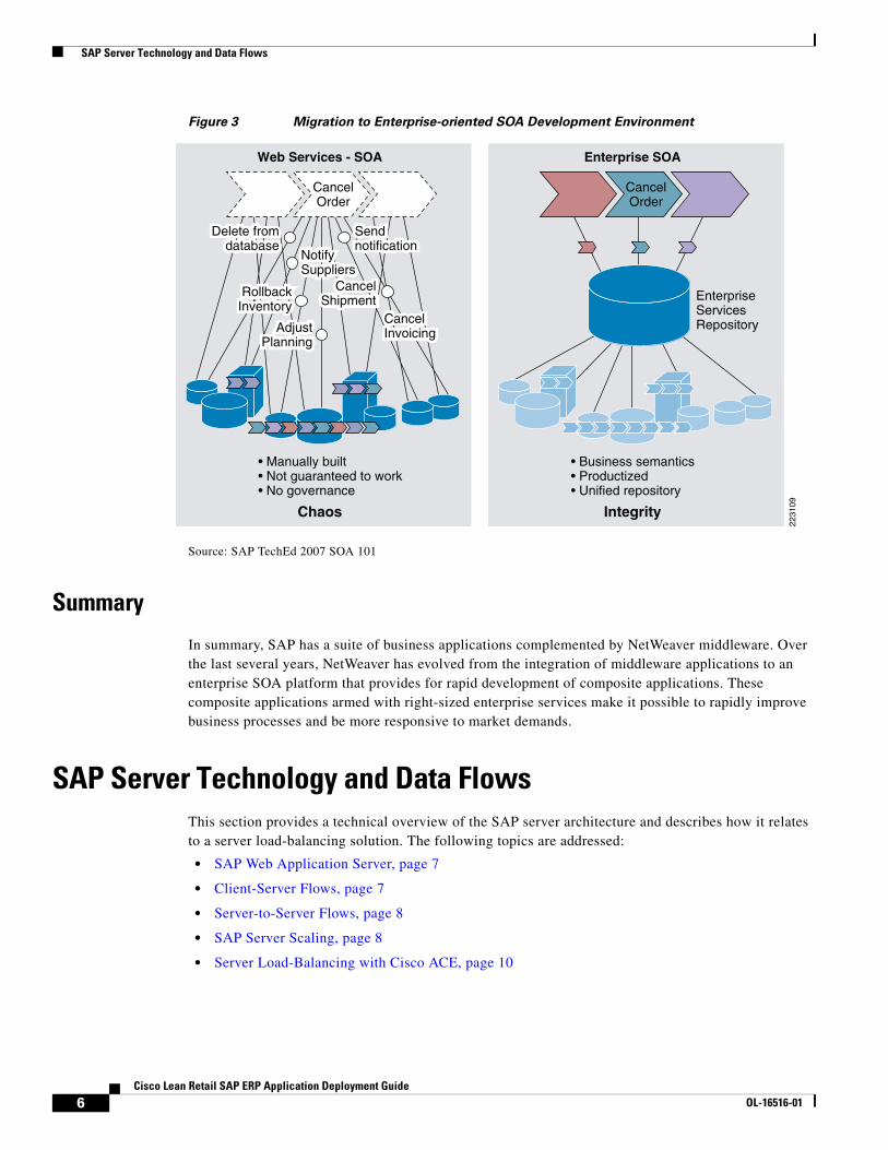
NetWeaver 7.1—Business Process PlatformWith NetWeaver 7.1, SAP introduces enterprise SOA, making SOA easier to use by applying business logic to the web services that are developed. SOA by itself could theoretically mean exposing every program as services, but this would be unwieldy and difficult to use. The services must be exposed at the correct level to a business process architect who might not understand the program underneath. Thus NetWeaver 7.1 is referred to as the business process platform because it business enables web services, where an enterprise service is an interface to a set of tasks that fit a specific business objective. See Figure 3.
2231
08
CRM
Application Components
Portal Rendering Devices Office RFID
ERM SCM ...
OtherApps
OtherPlatforms
OtherBusinesses
IndustryStandards
EnterpriseService
Repository
SAPxApps
SAP NetWeaver 2004s
myS
AP
200
5
PartnerxApps
CustomxApps
5Cisco Lean Retail SAP ERP Application Deployment Guide
OL-16516-01
SAP Server Technology and Data Flows
Figure 3 Migration to Enterprise-oriented SOA Development Environment
Source: SAP TechEd 2007 SOA 101
Summary
In summary, SAP has a suite of business applications complemented by NetWeaver middleware. Over the last several years, NetWeaver has evolved from the integration of middleware applications to an enterprise SOA platform that provides for rapid development of composite applications. These composite applications armed with right-sized enterprise services make it possible to rapidly improve business processes and be more responsive to market demands.
SAP Server Technology and Data FlowsThis section provides a technical overview of the SAP server architecture and describes how it relates to a server load-balancing solution. The following topics are addressed:
• SAP Web Application Server, page 7
• Client-Server Flows, page 7
• Server-to-Server Flows, page 8
• SAP Server Scaling, page 8
• Server Load-Balancing with Cisco ACE, page 10
2231
09
Web Services - SOA
Chaos
CancelOrder
Delete fromdatabase
• Manually built• Not guaranteed to work• No governance
Sendnotification
NotifySuppliers
CancelShipment
RollbackInventory
AdjustPlanning
CancelInvoicing
Enterprise SOA
Integrity
CancelOrder
• Business semantics• Productized• Unified repository
EnterpriseServicesRepository
6Cisco Lean Retail SAP ERP Application Deployment Guide
OL-16516-01
SAP Server Technology and Data Flows
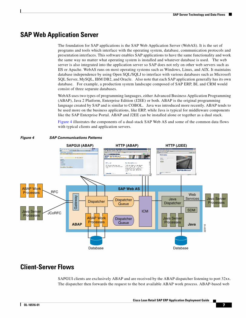
SAP Web Application ServerThe foundation for SAP applications is the SAP Web Application Server (WebAS). It is the set of programs and tools which interface with the operating system, database, communication protocols and presentation interfaces. This software enables SAP applications to have the same functionality and work the same way no matter what operating system is installed and whatever database is used. The web server is also integrated into the application server so SAP does not rely on other web servers such as IIS or Apache. WebAS runs on most operating systems such as Windows, Linux, and AIX. It maintains database independence by using Open SQL/SQLJ to interface with various databases such as Microsoft SQL Server, MySQL, IBM DB2, and Oracle. Also note that each SAP application generally has its own database. For example, a production system landscape composed of SAP ERP, BI, and CRM would consist of three separate databases.
WebAS uses two types of programming languages, either Advanced Business Application Programming (ABAP), Java 2 Platform, Enterprise Edition (J2EE) or both. ABAP is the original programming language created by SAP and is similar to COBOL. Java was introduced more recently. ABAP tends to be used more on the business applications, like ERP, while Java is typical for middleware components like the SAP Enterprise Portal. ABAP and J2EE can be installed alone or together as a dual stack.
Figure 4 illustrates the components of a dual-stack SAP Web AS and some of the common data flows with typical clients and application servers.
Figure 4 SAP Communications Patterns
Client-Server Flows
SAPGUI clients are exclusively ABAP and are received by the ABAP dispatcher listening to port 32xx. The dispatcher then forwards the request to the best available ABAP work process. ABAP-based web
Database
Gat
eway
Dispatcher
RFC
JCoRFC ICM
JavaDispatcher
WebServices
SDM
ABAP
SAP Web AS
SAPGUI (ABAP) HTTP (ABAP) HTTP (J2EE)
Java
2231
10
DispatcherQueue
DispatcherQueue
Database
ABAP WorkProcesses
ABAP WorkProcesses
Java ServerProcesses
Java ServerProcesses
Java ServerProcesses
7Cisco Lean Retail SAP ERP Application Deployment Guide
OL-16516-01
SAP Server Technology and Data Flows
requests are first received by the Internet Communication Manager (ICM)—which listens for HTTP on port 8000 by default, but can be configured to use any port. The ICM then parses the URL to determine if the session should be routed to the ABAP or Java dispatcher. While Java web sessions can also be routed through the ICM, in other cases—particularly in Java only servers like the SAP EP—the web sessions connect directly to the Java Dispatcher, which is listening on 5XX00 for HTTP and 5XX01 for SSL.
For a complete listing of ports used by SAP, refer to the following URL:
https://www.sdn.sap.com/irj/sdn/go/portal/prtroot/docs/library/uuid/4e515a43-0e01-0010-2da1-9bcc452c280b.
Server-to-Server FlowsCommon application-to-application flows include the following:
• Remote Function Call (RFC)—The RFC is a SAP protocol for interprocess communication between systems. The RFCs enable you to call and execute predefined functions in a remote system, or in the same system. The RFCs manage the communication process, parameter transfer, and error handling.
• SAP Java Connector (JCo)/RFC—The SAP JCo is an adapter that the Java-based servers use to execute RFC communications with ABAP servers. In the J2EE Engine the RFC functions are implemented by the JCo RFC Provider service, which is used for processing ABAP-to-Java requests. A feature is also provided for receiving calls from the SAP systems. This is done by registering the J2EE Engine as a RFC destination.
• XML/SOAP Web Services—Standard XML/SOAP messages are used for SOA communications. This is currently an area of growth for SAP as core processes are exposed as web services and leveraged in new ways with composite applications like the SAP xApps family.
SAP Server Scaling
SAP application servers scale by separating functions into a Central Instance (CI) and Dialog Instance (DI). See Figure 5. The CI contains the message and enqueue servers and is responsible for queuing and database locks, while the DIs perform the actual processing of the application. There is a single CI. For high availability, it is deployed in active/standby mode using the clustering software of the underlying platform. Processing capacity is increased by adding DIs and this is where load-balancing applies.
8Cisco Lean Retail SAP ERP Application Deployment Guide
OL-16516-01

SAP Server Technology and Data Flows
Figure 5 SAP Server Scaling
Source:https://www.sdn.sap.com/irj/servlet/prt/portal/prtroot/docs/library/uuid/c3d9d710-0d01-0010-7486-9a51ab92b927
Each SAP application scales in this way. Figure 6 illustrates the SAP server farm—multiple business and middleware applications, each with their own CI cluster, DI servers and database servers. Each of these are separate entities where various application and security optimizations may apply.
Figure 6 SAP Server Farm
MessageServer
SPOF
EnqueueServer
Dispatcher
DVEBMGS00
Internet Communication Manager Internet CommunicationManager
Web Application Server Abap Web AS Abap Web AS Java
Work Proc.1..m
Work Proc.1..q
MessageServer
SPOF - SCS01
EnqueueServer
Dispatcher
Central Instance Multiple Dialog Instances (1..s)
DVEBMGS00 D00 D00
Web Application Server Java
Server1..n
Server1..r
Dispatcher Dispatcher
2231
11
EP
2232
68
BI
ERP
CRM
XI
SRM
ERP
PLM
SCM
SRM
CRM
BI EP XI MI MDM
NetWeaverCAF ESR
9Cisco Lean Retail SAP ERP Application Deployment Guide
OL-16516-01
Data Center Design
Server Load-Balancing with Cisco ACELoad-balancing SAP with the Cisco ACE is focused on web transactions (not SAPGUI or RFC). The process proceeds as follows:
1. For client-server traffic, the client DNS request resolves to a virtual IP (VIP) address located on the Cisco ACE rather than the real server itself. The Cisco ACE then distributes the load to real servers using a configured server selection method such as weighted round robin. In most cases once a client session is directed to a server, ACE sticks all subsequent requests to that same server, typically using a cookie. Health probes are used to take non-responsive servers out of rotation.
2. For application-to-application web services traffic, the application first generates a request for the web services definition language (WSDL). This request is load balanced to a server, either the real server itself or on a central repository such as SAP's ESR. When the application receives the WSDL, it locates the URL to the service and generates a new request using that URL. This URL resolves to a VIP address on the Cisco ACE which in turn load-balances the request to a real server. Typically this web services request is a single request and therefore persistence is not required. If necessary, persistence can be provisioned in the same way as client-to-server sessions—the HTTP header for web services requests contains the saplb_* cookie (discussed below) and will also accept inserted cookies.
Classic SAP is not load-balanced by the Cisco ACE. Instead, it is load-balanced by the message server itself using a redirect approach. A typical process proceeds as follows:
1. A SAPGUI client connects directly to the message server.
2. The message server replies back to the client with an IP address and port for the best server instance.
3. The SAPGUI client connects to the DI directly.
Data Center DesignThis section describes how to design the data center architecture for a server farm using virtualization. It covers the following topics:
• SAP Portal Design, page 10
• Infrastructure Consolidation with Virtualization, page 13
• Security and Server Load-Balancing Integration, page 15
• Segmenting Security and Load Balancing with Roles-Based Access Control, page 16
• Segmenting Content Owners with Roles-Based Access Control, page 18
• Virtualization Design Considerations, page 19
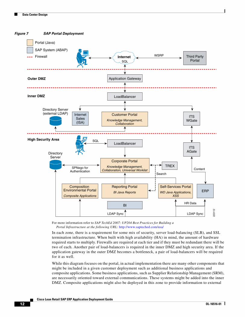
SAP Portal DesignFigure 7 shows an SAP portal design. There are three security zones, each separated by firewalls:
• The first zone is the outer DMZ and contains an application gateway. It is either clustered or load-balanced depending on the load requirement.
• The second zone is the inner DMZ and includes the customer portal and a web gateway to backend content. A customer, for example, might click on a link in the portal that requires an ERP transaction. The portal redirects the browser to the Internet Transaction Server (ITS). The ITS WGate is a web front-end that presents HTML pages to the user and links to the ITS AGate. The ITS
10Cisco Lean Retail SAP ERP Application Deployment Guide
OL-16516-01
Data Center Design
AGate translates the pages to R/3 transaction screens and forwards them to the ERP application server for processing. For more information on ITS, refer to the following URL: http://searchsap.techtarget.com/sDefinition/0,,sid21_gci822867,00.html.
Note There could be many variations of this type transaction, such as a chain of web services requests from the portal to a composite application, to a newer backend with a dual-stack of ABAP and Java. Exchange Infrastructure (XI) is also commonly in the mix. It translates between ABAP and Java environments, or web services and non-web services enabled hosts. (In this example, the Java systems are shown in orange and the ABAP systems in blue.)
• The third zone includes the corporate federated portal along with the backend systems and NetWeaver applications such as BI. This is the high-security zone that contains critical enterprise data.
11Cisco Lean Retail SAP ERP Application Deployment Guide
OL-16516-01
Data Center Design
Figure 7 SAP Portal Deployment
For more information refer to SAP TechEd 2007: UP204 Best Practices for Building a Portal Infrastructure at the following URL: http://www.sapteched.com/usa/
In each zone, there is a requirement for some mix of security, server load-balancing (SLB), and SSL termination infrastructure. When built with high availability (HA) in mind, the amount of hardware required starts to multiply. Firewalls are required at each tier and if they must be redundant there will be two of each. Another pair of load-balancers is required in the inner DMZ and high security area. If the application gateway in the outer DMZ becomes a bottleneck, a pair of load-balancers will be required for it as well.
While this diagram focuses on the portal, in actual implementation there are many other components that might be included in a given customer deployment such as additional business applications and composite applications. Some business applications, such as Supplier Relationship Management (SRM), are necessarily oriented toward external communications. These systems might be added into the inner DMZ. Composite applications might also be deployed in this zone to provide information to external
2231
12
InternetSales(ISA)
ERP
Third PartyPortal
ITSWGate
LoadBalancer
Customer Portal
Knowledge Management,Collaboration
Directory Server(external LDAP)
Portal (Java)
SAP System (ABAP)
Firewall Internet
Outer DMZ
Inner DMZ
High Security Area
Reporting Portal
BI Java Reports
Composition Environmental Portal
Composite Applications
Self-Services Portal
WD Java Applications,XSS
ITSAGate
LoadBalancer
BI
TREXCorporate Portal
Knowledge Management,Collaboration, Universal Worklist
DirectoryServer
Application Gateway
SQL
SQL
WSRP
Content
Search
HR Data
LDAP SyncLDAP Sync
SPNego forAuthentication
12Cisco Lean Retail SAP ERP Application Deployment Guide
OL-16516-01
Data Center Design
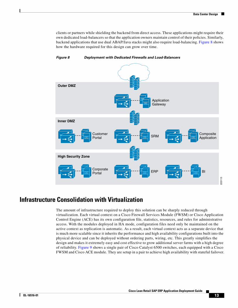
clients or partners while shielding the backend from direct access. These applications might require their own dedicated load-balancers so that the application owners maintain control of their policies. Similarly, backend applications that use dual ABAP/Java stacks might also require load-balancing. Figure 8 shows how the hardware required for this design can grow over time.
Figure 8 Deployment with Dedicated Firewalls and Load-Balancers
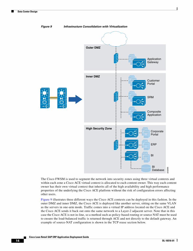
Infrastructure Consolidation with VirtualizationThe amount of infrastructure required to deploy this solution can be sharply reduced through virtualization. Each virtual context on a Cisco Firewall Services Module (FWSM) or Cisco Application Control Engine (ACE) has its own configuration file, statistics, resources, and rules for administrative access. With the modules deployed in HA mode, configuration files need only be maintained on the active context as replication is automatic. As a result, each virtual context acts as a separate device that is much more scalable since it inherits the performance and high availability configurations built into the physical device and can be deployed without ordering parts, wiring, etc. This greatly simplifies the design and makes it extremely easy and cost effective to grow additional server farms with a high degree of reliability. Figure 9 shows a single pair of Cisco Catalyst 6500 switches, each equipped with a Cisco FWSM and Cisco ACE module. They are setup in a pair to achieve high availability with stateful failover.
Outer DMZ
Inner DMZ
ApplicationGateway
SRMCompositeApplication
CustomerPortal
High Security Zone
ERP BICorporatePortal
2231
13
13Cisco Lean Retail SAP ERP Application Deployment Guide
OL-16516-01
Data Center Design
Figure 9 Infrastructure Consolidation with Virtualization
The Cisco FWSM is used to segment the network into security zones using three virtual contexts and within each zone a Cisco ACE virtual context is allocated to each content owner. This way each content owner has their own virtual context that inherits all of the high availability and high performance properties of the underlying the Cisco ACE platform without the risk of configuration errors affecting other users.
Figure 9 illustrates three different ways the Cisco ACE contexts can be deployed in this fashion. In the outer DMZ and inner DMZ, the Cisco ACE is deployed like another server, sitting on the same VLAN as the servers in one-arm mode. Traffic comes into a virtual IP address located on the Cisco ACE and the Cisco ACE sends it back out onto the same network to a Layer-2 adjacent server. Note that in this case the Cisco ACE is not in-line, so a method such as policy-based routing or source NAT must be used to ensure the load-balanced traffic is returned through ACE and not directly to the default gateway. An example of source-NAT configuration is shown in the TCP reuse section below.
BI
BIDatabase
ERP
CorporatePortal
Outer DMZ
Inner DMZ
ApplicationGateway
CompositeApplication
SRM
CustomerPortal
High Security Zone
2232
69
14Cisco Lean Retail SAP ERP Application Deployment Guide
OL-16516-01
Data Center Design
In the high security zone, two other deployment options are shown for the Cisco ACE virtual contexts. The corporate portal shows the Cisco ACE context in-line to add another layer of security, now in control of the content owner. Any connection to the corporate portal servers must now traverse the Cisco ACE and pass the security policies deployed in it. The third option is shown with the BI server farm. It shows the database (formerly assumed to be Layer-2 adjacent to the servers) on a separate segment on the Cisco ACE. Now BI application servers communicating to the database are limited to only relevant communications, typically SQL. This prevents a compromised application server from being able to scan and attack other services on the database server that may be vulnerable.
Note that when an application server communicates with a database through the Cisco ACE, there may be a need for extended flow timeouts. Usually, this is not an issue but some implementations optimize performance by pre-opening the database connection, making database opens quicker and more efficient. The Cisco ACE, however, times out a flow after one hour by default. This can break communications if the server does not attempt to reestablish the connection. The example below shows how to set the inactivity timeout to infinity so that these connections are never timed out. This configuration should be applied as specifically as possible so that stale flows do not accumulate. In this example, the timeout is set only for flows targeting port 1521 and originating from the server side VLAN, which in this example is VLAN 10.
parameter-map type connection DB set timeout inactivity 0
class-map match-all DB-class match port tcp eq 1521
policy-map multi-match DB-policy class DB-class connection advanced-options DB
interface vlan 10description server side interface service-policy input DB-policy
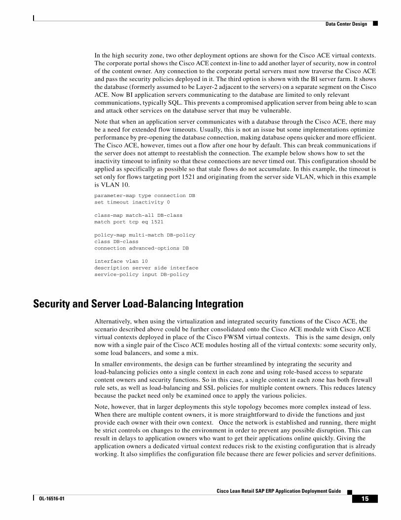
Security and Server Load-Balancing IntegrationAlternatively, when using the virtualization and integrated security functions of the Cisco ACE, the scenario described above could be further consolidated onto the Cisco ACE module with Cisco ACE virtual contexts deployed in place of the Cisco FWSM virtual contexts. This is the same design, only now with a single pair of the Cisco ACE modules hosting all of the virtual contexts: some security only, some load balancers, and some a mix.
In smaller environments, the design can be further streamlined by integrating the security and load-balancing policies onto a single context in each zone and using role-based access to separate content owners and security functions. So in this case, a single context in each zone has both firewall rule sets, as well as load-balancing and SSL policies for multiple content owners. This reduces latency because the packet need only be examined once to apply the various policies.
Note, however, that in larger deployments this style topology becomes more complex instead of less. When there are multiple content owners, it is more straightforward to divide the functions and just provide each owner with their own context. Once the network is established and running, there might be strict controls on changes to the environment in order to prevent any possible disruption. This can result in delays to application owners who want to get their applications online quickly. Giving the application owners a dedicated virtual context reduces risk to the existing configuration that is already working. It also simplifies the configuration file because there are fewer policies and server definitions.
15Cisco Lean Retail SAP ERP Application Deployment Guide
OL-16516-01
Data Center Design
Similarly, show commands only reflect the connections actually going to the owner's servers. As a result, the topology in Figure 10 should be used for smaller scale deployments. Figure 10 shows the above topology streamlined using only three Cisco ACE contexts in each module.
Figure 10 Deployment with Integrated Security, Load-balancing and SSL
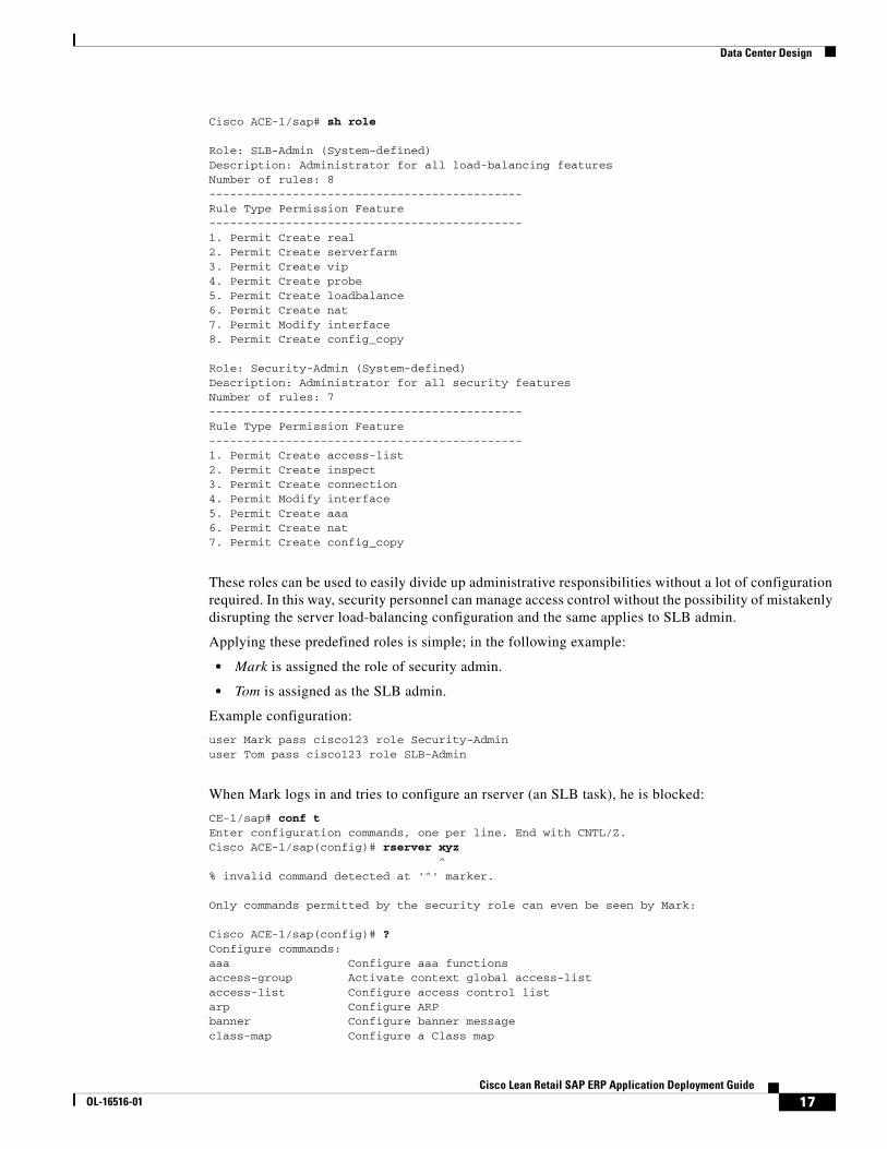
Segmenting Security and Load Balancing with Roles-Based Access ControlWhen security and load-balancing functions coexist on the same context as shown in the preceding example, there might be a need to further segment administrative control if different teams are responsible for these functions. With roles-based access control (RBAC) enabled on the Cisco ACE, the security administrator can only access the security portion of the configuration. Similarly, the server administrator can only access load-balancing related functions.
The Cisco ACE comes prepackaged with a number of predefined roles. The SLB-Admin, Security-Admin roles are shown in the configuration that follows. The load-balancing commands are accessible to the SLB-Admin and security-related commands are associated with the Security-Admin role.
BI
ERP
CorporatePortal
Outer DMZ
Inner DMZ
ApplicationGateway
CompositeApplication
SRM
CustomerPortal
High Security Zone
2231
14
16Cisco Lean Retail SAP ERP Application Deployment Guide
OL-16516-01
Data Center Design
Cisco ACE-1/sap# sh role
Role: SLB-Admin (System-defined) Description: Administrator for all load-balancing features Number of rules: 8 --------------------------------------------- Rule Type Permission Feature --------------------------------------------- 1. Permit Create real 2. Permit Create serverfarm 3. Permit Create vip 4. Permit Create probe 5. Permit Create loadbalance 6. Permit Create nat 7. Permit Modify interface 8. Permit Create config_copy
Role: Security-Admin (System-defined) Description: Administrator for all security features Number of rules: 7 --------------------------------------------- Rule Type Permission Feature --------------------------------------------- 1. Permit Create access-list 2. Permit Create inspect 3. Permit Create connection 4. Permit Modify interface 5. Permit Create aaa 6. Permit Create nat 7. Permit Create config_copy
These roles can be used to easily divide up administrative responsibilities without a lot of configuration required. In this way, security personnel can manage access control without the possibility of mistakenly disrupting the server load-balancing configuration and the same applies to SLB admin.
Applying these predefined roles is simple; in the following example:
• Mark is assigned the role of security admin.
• Tom is assigned as the SLB admin.
Example configuration:
user Mark pass cisco123 role Security-Admin user Tom pass cisco123 role SLB-Admin
When Mark logs in and tries to configure an rserver (an SLB task), he is blocked:
CE-1/sap# conf tEnter configuration commands, one per line. End with CNTL/Z.Cisco ACE-1/sap(config)# rserver xyz ^% invalid command detected at '^' marker.
Only commands permitted by the security role can even be seen by Mark:
Cisco ACE-1/sap(config)# ?Configure commands: aaa Configure aaa functions access-group Activate context global access-list access-list Configure access control list arp Configure ARP banner Configure banner message class-map Configure a Class map
17Cisco Lean Retail SAP ERP Application Deployment Guide
OL-16516-01
Data Center Design
do EXEC command end Exit from configure mode exit Exit from configure mode interface Configure an interface ip Configure IP features ldap-server Configure LDAP related parameters no Negate a command or set its defaults parameter-map Configure a parameter map policy-map Configure a policy map radius-server Configure RADIUS related parameters service-policy Enter service policy to be applied to this context snmp-server Configure snmp server ssh Configure SSH parameters tacacs-server Configure TACACS+ server related parameters timeout Configure the maximum timeout duration username Configure user information.
Similarly, Tom, the SLB admin, sees only commands related to his role:
Cisco ACE-1/sap# conf tEnter configuration commands, one per line. End with CNTL/Z.Cisco ACE-1/sap(config)# ?
Configure commands: access-group Activate context global access-list arp Configure ARP class-map Configure a Class map do EXEC command end Exit from configure mode exit Exit from configure mode interface Configure an interface ip Configure IP features no Negate a command or set its defaults parameter-map Configure a parameter map
policy-map Configure a policy map probe Configure probe rserver Configure rserver script Configure script file and tasks serverfarm Configure serverfarm service-policy Enter service policy to be applied to this context snmp-server Configure snmp server ssh Configure SSH parameters timeout Configure the maximum timeout duration username Configure user information.Cisco ACE-1/sap(config)#
Segmenting Content Owners with Roles-Based Access ControlRoles-based access control can also be used to support multiple content owners on a single context with the use of domains. The SCM administrators, for example, could be given full control over their own load-balancing domain within the context while being prevented from altering configurations in other domains.
The following configuration example shows that Tom, the SCM administrator, is allowed to modify only the SCM policy-map. A domain, SCM, is created, and the policy-map called SCM-policy is added to that domain, and then Tom is associated to the domain.
domain SCM
18Cisco Lean Retail SAP ERP Application Deployment Guide
OL-16516-01
Data Center Design
add-object policy-map SCM-policyusername Tom password cisco123 role SLB-Admin domain SCM
Now, when Tom attempts to edit a policy not included in his domain, he is blocked (as shown in the following configuration input example) when he attempts to edit portal policy. However, when Tom edits the allowed SCM policy, the action is permitted:
Cisco ACE-1/sap(config)# policy-map type loadbalance first Portal-policyError: object being referred to is not part of User's domainCisco ACE-1/sap(config)# policy-map type loadbalance first SCM-policy Cisco ACE-1/sap(config-pmap-lb)#
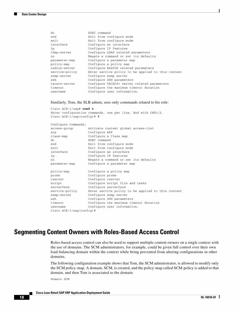
Virtualization Design ConsiderationsThis section shows how to deploy a SAP server farm like the one above using the Cisco Catalyst 6500 and related service modules. Figure 11 shows a Cisco ACE module with an Admin context and three contexts for SAP servers. Each context is allocated VLAN interfaces per the design requirement.
Figure 11 Cisco ACE Module Layout for SAP Server Farm
VLAN100
Catalyst6500
AdminContext
VLAN10
VLAN20
VLAN30
OuterDMZ
VLAN30
VLAN40
VLAN50
VLAN50
VLAN60
InnerDMZ
HighSecurity
Zone
2231
16
19Cisco Lean Retail SAP ERP Application Deployment Guide
OL-16516-01
Data Center Design
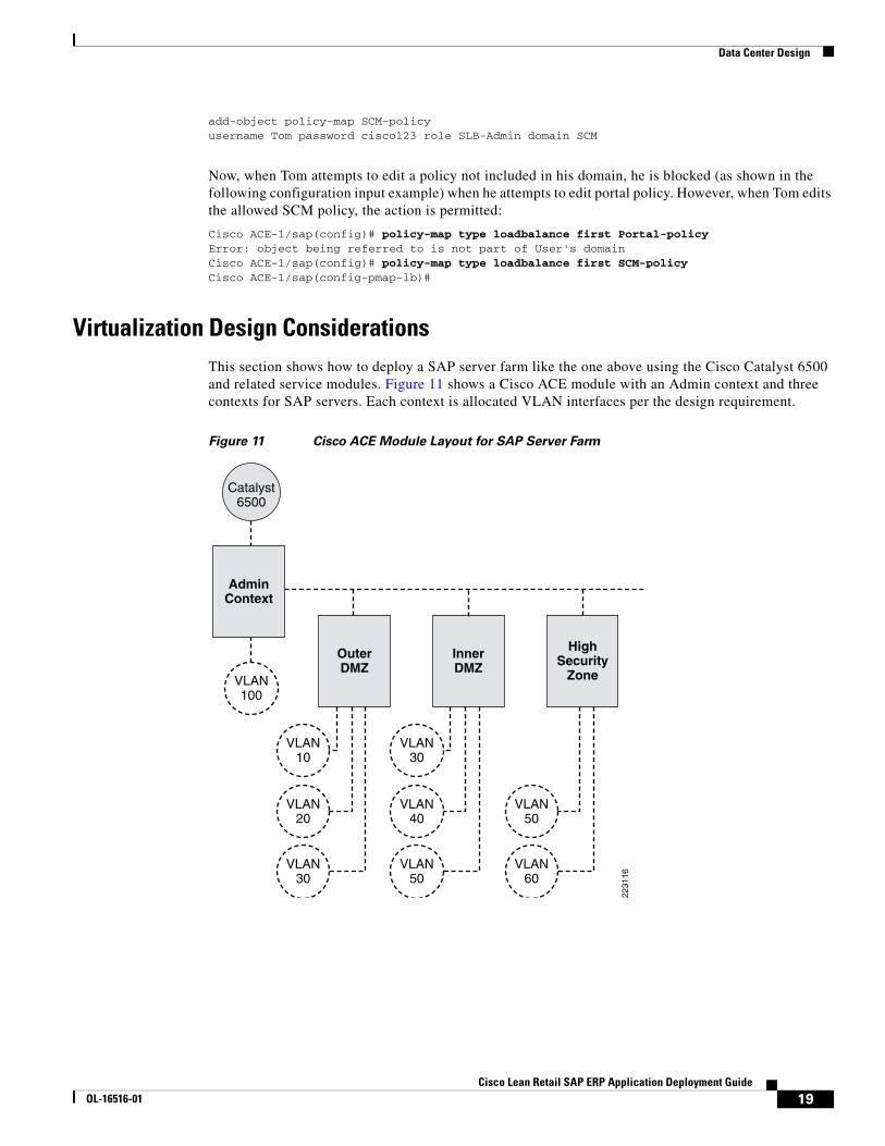
Figure 12 shows how these contexts and VLANs fit within the overall data center architecture.
Figure 12 Data Center Architectural View
The following are important to note about the design illustrated in Figure 12:
• Only VLANs 20, 40, and 60 will be trunked to the access switches where the servers in each zone ultimately connect.
• All the Cisco ACE VLANs are trunked between the two aggregation switches (including the failover trunk VLAN—not shown),
• The Cisco ACE contexts are shown to be all primary on the left and standby on the right, but these positions can be alternated in order to balance the processing load between the two Cisco ACE modules for an active-active configuration.
• The Cisco Network Analysis Module (NAM), shown by an icon in the upper corner of each aggregation switch, provides centralized visibility into all VLANs for troubleshooting and performance monitoring. Remote SPAN (RSPAN) can be used on the access switch to provide greater visibility to the servers.
20
NAMMSFC
Core
Access
Aggregation
IDSM
40
60
20 40 60
20
NAMMSFC
10
30
50
Access
IDSM
40
6022
3117
20Cisco Lean Retail SAP ERP Application Deployment Guide
OL-16516-01
Cisco ACE Module Implementation and Configuration
• This design provides the flexibility for intrusion detection systems (IDS) or intrusion prevention systems (IPS) to inspect the traffic. Even end-to-end SSL traffic can be secured in this way. For example, the outer DMZ context can decrypt the SSL and send it to the proxy. When the proxy sends HTTP down to the next context, IDS inspection can be applied to the clear text on VLAN 30, then the traffic can be encrypted again toward the servers on the inner DMZ context.
• All the Cisco ACE contexts are shown in routed mode. The Admin context is not shown. When chaining multiple contexts together in this way, routed mode provides a stable and loop-free environment.
• This design shows dedicated VLANs for servers. The inter-context VLANs (30 and 50) can be used instead, but—because there is no shortage of VLAN interfaces—having a dedicated interface for the servers might allow more flexibility with the access restrictions.
This document does not cover all configurations associated with an HA design, but does highlight the configurations required for accomplishing the tasks specific to the SAP deployment.
Cisco ACE Module Implementation and ConfigurationThis section describes the steps required to configure the Cisco ACE module for a SAP deployment using the above scenario as an example. It is based on testing with SAP ERP 6.0 and SAP NetWeaver 7.0. It includes the following topics:
• Admin Context Setup, page 22
• Baseline User Context Configuration, page 22
• Security, page 23
• Server Farms, page 24
• Basic Load Balancing, page 24
• Health Monitoring, page 25
• Health Monitoring for Web Services, page 26
• Session Persistence, page 27
• SSL Termination, page 31
• HTTP Header Rewrite (Cisco ACE 2.0), page 32
• HTTP Header Insert, page 33
• Persistence Rebalance, page 33
• Redirect Server, page 33
• Impact of TCP Reuse and SSL Termination on Server CPU, page 34
• Backend Encryption, page 34
• SSL Reuse (Cisco ACE 2.0), page 35
• TCP Reuse, page 36
• WAN Tuning with Cisco ACE, page 38
• Optimization Summary, page 39
21Cisco Lean Retail SAP ERP Application Deployment Guide
OL-16516-01
Cisco ACE Module Implementation and Configuration
Admin Context SetupThe first step in setting up the Cisco ACE is to allocate a VLAN in the Cisco Catalyst 6500 and to set up the Admin context. The steps that follow describe this process.
Step 1 First create the VLANs on the Cisco Catalyst and assign them to the Cisco ACE.
Cisco Catalyst 6500 configuration:
vlan 10vlan 20! etc.svclc vlan-group 1 10,20,30,40,50,60,100
Step 2 On the Cisco ACE, define the three SAP virtual contexts and their VLANs.
Cisco ACE Admin context configuration:
context InnerDMZ allocate-interface vlan 10 allocate-interface vlan 20 allocate-interface vlan 30context OuterDMZ allocate-interface vlan 30 allocate-interface vlan 40 allocate-interface vlan 50context Backend allocate-interface vlan 50 allocate-interface vlan 60
Baseline User Context ConfigurationThere are a few things that must be configured on any user context, without regard to the load-balancing or security policies. These are as follows:
• Since these are routed contexts, the interfaces need IP addresses. (Alias addresses for HA are not shown, but are required for a redundant scenario.)
• Static routes and default routes are required.
• A management access policy must be assigned to an interface, if there is to be access to the context outside of the Admin context (this is recommended if each context has a different owner, since the Admin context has unrestricted access to all the other contexts). VLAN 20 is selected in this example.
• An access control list (ACL) must be defined on each interface. This is covered in Security, page 23.
Here is an example of the outer DMZ context configuration:
class-map type management match-any REMOTE-ACCESS description "Define Allowed Mgmt Traffic" 2 match protocol http any 3 match protocol https any 4 match protocol telnet any 5 match protocol ssh any 6 match protocol xml-https any 7 match protocol snmp any 8 match protocol icmp any
22Cisco Lean Retail SAP ERP Application Deployment Guide
OL-16516-01
Cisco ACE Module Implementation and Configuration
policy-map type management first-match REMOTE-MGMT class REMOTE-ACCESS permit
interface vlan 10 description outerDMZ outside interface ip address 10.10.1.1 255.255.255.0 no shutdown
interface vlan 20 description Proxy VLAN ip address 10.10.2.1 255.255.255.0 service-policy input REMOTE-MGMT no shutdown
interface vlan 30 description outer DMZ inside interface ip address 10.10.3.1 255.255.255.0 no shutdown
ip route 0.0.0.0 0.0.0.0 10.10.1.2
SecurityEach interface on the Cisco ACE applies stateful inspection rules that explicitly allow or deny specified traffic patterns. Since the ACLs are stateful, the return path for the traffic need not be specified. The syntax is standard Cisco extended ACL configuration commands using access-list commands to create the rules and access-group commands to apply the rules to interfaces. For example, on the outer DMZ, context traffic could be limited to HTTP and SSL destined to the VIP address for the proxy. All other traffic is denied by default.
Example configuration:
access-list VIP line 10 extended permit tcp any eq www host 10.10.2.10 access-list VIP line 20 extended permit tcp any eq https host 10.10.2.10
interface vlan 10 description outerDMZ outside interface access-group input VIP
On the inner DMZ, since the only traffic coming in should be coming from the proxy, the traffic could be limited to HTTP from the proxy real address, destined to the VIP address for the customer portal. Similar entries could be made for traffic to the Composite Application VIP address and the SRM VIP address. All other traffic is denied by default.
Example configuration:
access-list PROXY_VIP line 10 extended permit tcp host 10.10.2.10 eq www host 3.3.3.3
interface vlan 30 description innerDMZ outside interface access-group input PROXY_VIP
23Cisco Lean Retail SAP ERP Application Deployment Guide
OL-16516-01
Cisco ACE Module Implementation and Configuration
Server FarmsEach real server must be defined as a rserver and again in a server farm, if there is to be port translation—such as port 80 to 50000—defined in the serverfarm configuration. Probes can be attached to the rserver or the server farm. Probes are described in the Health Monitoring, page 25. The following configuration example shows a single system hosting two server farms - one for HTTP (50000, 50200) and another for HTTPS (50001, 50201):
rserver host SAP-EP description "SAP Enterprise Portal" ip address 169.145.90.11 inservice
serverfarm host EP-HTTP rserver SAP-EP 50000 inservice rserver SAP-EP 50200 inservice
serverfarm host EP-HTTPS rserver SAP-EP 50001 inservice rserver SAP-EP 50201 inservice
Basic Load BalancingTo load balance connections to a server farm, there need to be at least four elements in place: a virtual IP address (VIP) /port, a load balancing policy, a multi-match policy, and a service-policy on the interface where the requests come in. Below is an example of the minimum components to accomplish basic load balancing to the EP-HTTP server farm shown above. The example has the following:
• A class map, HTTP-VIP, set up to match incoming port 80 requests to a VIP of 169.145.90.116.
• A load balancing policy, EP-HTTP-policy, that sends requests to the EP-HTTP server farm.
• A multi-match policy, SLB-policy, that links the class-map to the load balance policy. The multi-match policy is tied to an interface, VLAN 200, where the requests originate.
class-map match-any HTTP-VIP match virtual-address 169.145.90.116 tcp eq www
policy-map type loadbalance first-match EP-HTTP-policy class class-default serverfarm EP-HTTP
policy-map multi-match SLB-policy class HTTP-VIP loadbalance vip inservice loadbalance policy EP-HTTP-policy
interface vlan 30 description innerDMZ outside interface service-policy input SLB-policy
24Cisco Lean Retail SAP ERP Application Deployment Guide
OL-16516-01
Cisco ACE Module Implementation and Configuration
Multiple VIP class-maps can be assigned to a single multi-match policy. So if we want port 80 traffic to go to a different server farm than port 443 traffic, we create another class-map that matches the same VIP but on port 443 instead of port 80. Then create a load-balance policy that maps to the HTTPS server farm and add these pieces to the multi-match policy with an additional class statement.
class-map match-any HTTPS-VIP match virtual-address 169.145.90.116 tcp eq https
policy-map type loadbalance first-match epSAP-s class class-default serverfarm EP-HTTPS
policy-map multi-match SLB-policy class HTTP-VIP loadbalance vip inservice loadbalance policy EP-HTTP-policy class HTTPS-VIP loadbalance vip inservice loadbalance policy epSAP-s
This shows the basics of the configuration process to achieve load balancing: rserver, server farm, VIP class map, loadbalance policy, multimatch policy, and service policy. As shown below, there are a number of enhancements to this baseline to meet the needs of an SAP deployment.
Health MonitoringTo achieve high availability in the server farm, the load-balancer needs a way to determine whether the server is able to properly service a client request. Ideally, the probe should capture all information necessary to verify this capability. Sending a ping verifies the host is available, but not the application. A web page probe verifies that the application is running but not necessarily its connection to the database. It is possible to create multiple probes testing the state of the application as well as the database. However, in the case of the SAP EP, a database connection is required to deliver the portal logon page. A single probe to the /irj/portal URL verifies host, application, and database availability. The example configuration that follows illustrates configuring a probe to the irj/portal URL that expects a 200 OK from the server in order to consider the server as up. If the database is unable to respond to the application server, it will not return a 200 OK to this probe and will ultimately be taken out of service. Note that here since the two servers are running on the same physical host with different port numbers, the probes are assigned as subcommands to the rserver command rather than the serverfarm command. When all the servers share the same port number, the probe need only be assigned once for the entire server farm.
Example configuration:
probe http PORTAL-50000 description http-probe port 50000 interval 20 passdetect interval 10 request method get url /irj/portal expect status 200 200
probe http PORTAL-50200 description http-probe port 50200 interval 20 passdetect interval 10 request method get url /irj/portal expect status 200 200
25Cisco Lean Retail SAP ERP Application Deployment Guide
OL-16516-01
Cisco ACE Module Implementation and Configuration
serverfarm host EP-HTTP rserver SAP-EP 50000 probe PORTAL-50000 rserver SAP-EP 50200 probe PORTAL-50200
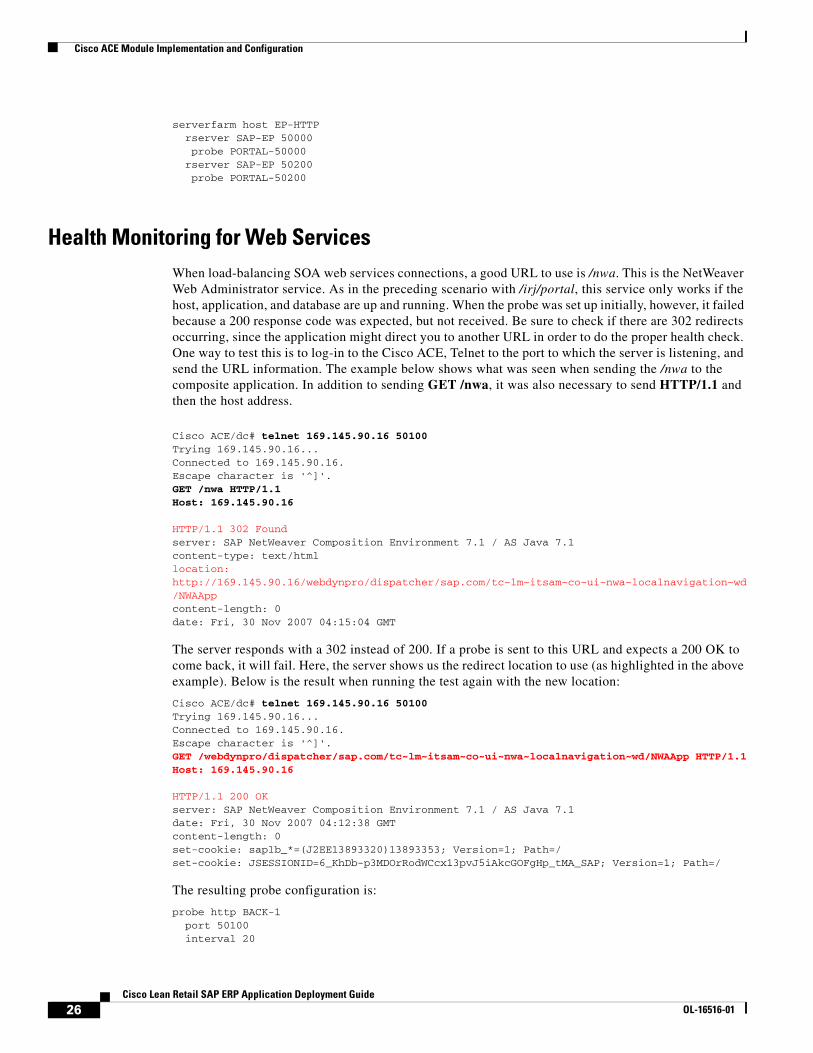
Health Monitoring for Web ServicesWhen load-balancing SOA web services connections, a good URL to use is /nwa. This is the NetWeaver Web Administrator service. As in the preceding scenario with /irj/portal, this service only works if the host, application, and database are up and running. When the probe was set up initially, however, it failed because a 200 response code was expected, but not received. Be sure to check if there are 302 redirects occurring, since the application might direct you to another URL in order to do the proper health check. One way to test this is to log-in to the Cisco ACE, Telnet to the port to which the server is listening, and send the URL information. The example below shows what was seen when sending the /nwa to the composite application. In addition to sending GET /nwa, it was also necessary to send HTTP/1.1 and then the host address.
Cisco ACE/dc# telnet 169.145.90.16 50100Trying 169.145.90.16...Connected to 169.145.90.16.Escape character is '^]'.GET /nwa HTTP/1.1Host: 169.145.90.16
HTTP/1.1 302 Foundserver: SAP NetWeaver Composition Environment 7.1 / AS Java 7.1content-type: text/htmllocation: http://169.145.90.16/webdynpro/dispatcher/sap.com/tc~lm~itsam~co~ui~nwa~localnavigation~wd/NWAAppcontent-length: 0date: Fri, 30 Nov 2007 04:15:04 GMT
The server responds with a 302 instead of 200. If a probe is sent to this URL and expects a 200 OK to come back, it will fail. Here, the server shows us the redirect location to use (as highlighted in the above example). Below is the result when running the test again with the new location:
Cisco ACE/dc# telnet 169.145.90.16 50100Trying 169.145.90.16...Connected to 169.145.90.16.Escape character is '^]'.GET /webdynpro/dispatcher/sap.com/tc~lm~itsam~co~ui~nwa~localnavigation~wd/NWAApp HTTP/1.1Host: 169.145.90.16
HTTP/1.1 200 OKserver: SAP NetWeaver Composition Environment 7.1 / AS Java 7.1date: Fri, 30 Nov 2007 04:12:38 GMTcontent-length: 0set-cookie: saplb_*=(J2EE13893320)13893353; Version=1; Path=/set-cookie: JSESSIONID=6_KhDb-p3MDOrRodWCcx13pvJ5iAkcGOFgHp_tMA_SAP; Version=1; Path=/
The resulting probe configuration is:
probe http BACK-1 port 50100 interval 20
26Cisco Lean Retail SAP ERP Application Deployment Guide
OL-16516-01
Cisco ACE Module Implementation and Configuration
passdetect interval 10 request method get url /webdynpro/dispatcher/sap.com/tc~lm~itsam~co~ui~nwa~localnavigation~wd/NWAApp expect status 200 200
Session PersistenceOnce an SAP user logs into an instance of the portal, all subsequent requests must be sent to that same server. If each new request from a client is load-balanced to a different server, within a few clicks the session is broken. To ensure session persistence, some form of stickiness must be configured either based on the user's IP address or a session cookie.
Stickiness is one of many resources in the Cisco ACE that can be allocated to a virtual context. Cisco ACE supports count limits on connections, xlates, management sessions, proxy connections, ACL memory, and regexp. It also supports rate-limits on connections per second, fixup per second, bandwidth, SSL connections per second, MAC-miss rate, and management traffic rate. Generally, if there is no specific configuration for resource allocation, each virtual context on a Cisco ACE has access to all the resources. Stickiness, however, must be configured explicitly on the Admin context before persistence can be configured on an individual context. In this example, each virtual context that is a member of the PERSIST resource class is entitled to at least 20 percent and no more than 20 percent of the total sticky resources in the Cisco ACE. There are no limitations on other Cisco ACE resources.
Example configuration:
resource-class PERSIST limit-resource all minimum 0.00 maximum unlimited limit-resource sticky minimum 20.00 maximum equal-to-min
context InnerDMZ member PERSIST
Once sticky resources have been allocated to a context, persistence can be configured on that context. Here, we look at three methods—source IP, cookie insert, and cookie learning. Source IP address requires no Layer 7 inspection and or SSL termination, but is ineffective if there are proxy servers. Cookie-based persistence methods require an inspection of the HTTP header and therefore require SSL termination. Cookie insert can be done without any knowledge of how cookies are used by the server. As such, it is a generic method that can be used across the board. Cookie learning works when you know which cookie to base the persistence on. The only real advantage of using it with SAP is the cookie value contains the node ID of the server which enables you to easily see by looking at the client's cookie what node the client has connected to. Each of these methods were tested and are described below.
Source IP Persistence
Source IP is the simplest method to assert persistence because it requires no inspection of the HTTP header. Even SSL encrypted sessions carry the IP address in the clear, so source IP sticky can be applied without terminating SSL.
To configure it on the Cisco ACE, first create a sticky server farm (which references one of the real server farms configured above) and then assign it to the loadbalance policy.
Example configuration:
sticky ip-netmask 255.255.255.255 address source ep-sourceIP timeout 10 serverfarm EP-HTTP
27Cisco Lean Retail SAP ERP Application Deployment Guide
OL-16516-01
Cisco ACE Module Implementation and Configuration
policy-map type loadbalance first-match basic-slb class class-default sticky-serverfarm ep-sourceIP
To see which server a client has to, use the show sticky data client x.x.x.x command. Example:
Cisco ACE-1/sap# show sticky data client 12.20.15.15sticky group : ep-stickytype : IP timeout : 10 timeout-activeconns : FALSE sticky-entry rserver-instance time-to-expire flags ------------------+----------------------+--------------+-------+ 202641167 ep1:51000 599 -
Cookie Persistence
Persistence based on the source IP address can work well, but if the clients go through a proxy, they will all be sent to the same server, and the load is not balanced evenly. Cookie sticky avoids this problem by maintaining persistence at the session level based on the value of a cookie in the HTTP header. Cisco ACE can either learn the cookie set by the application or it can insert its own cookie into the header.
Cookie insertion is usually a good option if it is not clear which cookie should be used for load-balancing. It is not disruptive to the SAP server and can be counted on reliably for session persistence. When you create a static sticky entry, Cisco ACE places the entry in the sticky table immediately. Static entries remain in the sticky database until you remove them from the configuration.
The sticky configuration for cookie insert is similar to source IP sticky—you create a sticky server farm and apply it to the loadbalance policy.
Example configuration:
sticky http-cookie ace_cookie ep-insert cookie insert browser-expire replicate sticky serverfarm EP-HTTP
policy-map type loadbalance http first-match ep-policy class class-default sticky-serverfarm ep-insert
To see the sticky database on inserted cookies, use the static keyword:
switch/SAP-Datacenter# show sticky data staticsticky group : ep-inserttype : HTTP-COOKIEtimeout : 1440 timeout-activeconns : FALSE sticky-entry rserver-instance time-to-expire flags ---------------------+--------------------------------+--------------+-------+ 8406590389602098862 SAP-EP:50000 never sticky group : ep-inserttype : HTTP-COOKIEtimeout : 1440 timeout-activeconns : FALSE sticky-entry rserver-instance time-to-expire flags ---------------------+--------------------------------+--------------+-------+ 18052788081821769859 SAP-EP:50200 never
Note When static cookies are used there will only be one entry in the cookie database per real server. So, if ace-cookie is the only cookie defined and there are two servers, there will only be two entries in the sticky database, even if there are thousands of user sessions.
28Cisco Lean Retail SAP ERP Application Deployment Guide
OL-16516-01
Cisco ACE Module Implementation and Configuration
Dynamic Cookie Learning
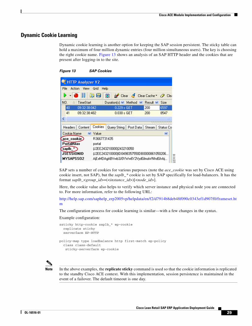
Dynamic cookie learning is another option for keeping the SAP session persistent. The sticky table can hold a maximum of four million dynamic entries (four million simultaneous users). The key is choosing the right cookie name. Figure 13 shows an analysis of an SAP HTTP header and the cookies that are present after logging-in to the site.
Figure 13 SAP Cookies
SAP sets a number of cookies for various purposes (note the ace_cookie was set by Cisco ACE using cookie insert, not SAP), but the saplb_* cookie is set by SAP specifically for load-balancers. It has the format saplb_<group_id>=(<instance_id>)[<node_id>].
Here, the cookie value also helps to verify which server instance and physical node you are connected to. For more information, refer to the following URL:
http://help.sap.com/saphelp_erp2005vp/helpdata/en/f2/d7914b8deb48f090c0343ef1d907f0/frameset.htm
The configuration process for cookie learning is similar—with a few changes in the syntax.
Example configuration:
ssticky http-cookie saplb_* ep-cookie replicate sticky serverfarm EP-HTTP
policy-map type loadbalance http first-match ep-policy class class-default sticky-serverfarm ep-cookie
Note In the above examples, the replicate sticky command is used so that the cookie information is replicated to the standby Cisco ACE context. With this implementation, session persistence is maintained in the event of a failover. The default timeout is one day.
29Cisco Lean Retail SAP ERP Application Deployment Guide
OL-16516-01
Cisco ACE Module Implementation and Configuration
The show sticky data command retrieves the active sticky entries that have been dynamically learned. The value shown is not the actual cookie value, but a function of it created by Cisco ACE.
Example configuration:
switch/SAP-Datacenter# show sticky datasticky group : ep-cookietype : HTTP-COOKIEtimeout : 100 timeout-activeconns : FALSE sticky-entry rserver-instance time-to-expire flags ---------------------+--------------------------------+--------------+-------+ 6026630525409626373 SAP-EP:50000 5983 switch/SAP-Datacenter# show sticky datasticky group : ep-cookietype : HTTP-COOKIEtimeout : 100 timeout-activeconns : FALSE sticky-entry rserver-instance time-to-expire flags ---------------------+--------------------------------+--------------+-------+ 6026630525409626373 SAP-EP:50000 5938 -
Tuning the HTTP Header Parsing
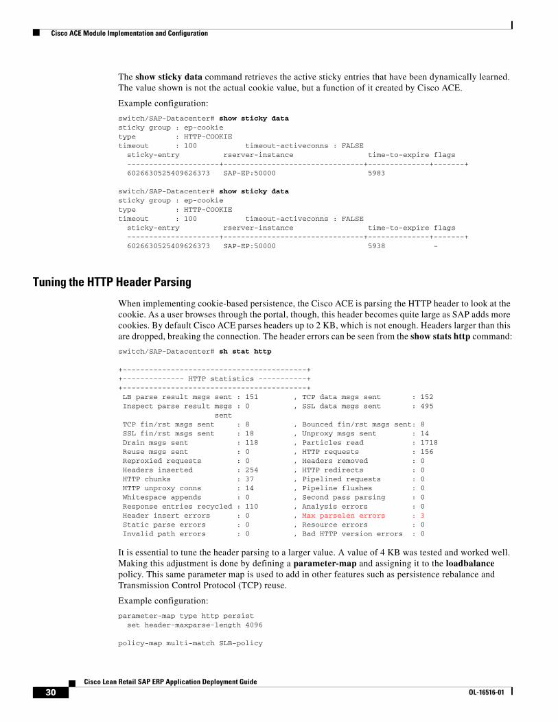
When implementing cookie-based persistence, the Cisco ACE is parsing the HTTP header to look at the cookie. As a user browses through the portal, though, this header becomes quite large as SAP adds more cookies. By default Cisco ACE parses headers up to 2 KB, which is not enough. Headers larger than this are dropped, breaking the connection. The header errors can be seen from the show stats http command:
switch/SAP-Datacenter# sh stat http
+------------------------------------------++-------------- HTTP statistics -----------++------------------------------------------+ LB parse result msgs sent : 151 , TCP data msgs sent : 152 Inspect parse result msgs : 0 , SSL data msgs sent : 495 sent TCP fin/rst msgs sent : 8 , Bounced fin/rst msgs sent: 8 SSL fin/rst msgs sent : 18 , Unproxy msgs sent : 14 Drain msgs sent : 118 , Particles read : 1718 Reuse msgs sent : 0 , HTTP requests : 156 Reproxied requests : 0 , Headers removed : 0 Headers inserted : 254 , HTTP redirects : 0 HTTP chunks : 37 , Pipelined requests : 0 HTTP unproxy conns : 14 , Pipeline flushes : 0 Whitespace appends : 0 , Second pass parsing : 0 Response entries recycled : 110 , Analysis errors : 0 Header insert errors : 0 , Max parselen errors : 3 Static parse errors : 0 , Resource errors : 0 Invalid path errors : 0 , Bad HTTP version errors : 0
It is essential to tune the header parsing to a larger value. A value of 4 KB was tested and worked well. Making this adjustment is done by defining a parameter-map and assigning it to the loadbalance policy. This same parameter map is used to add in other features such as persistence rebalance and Transmission Control Protocol (TCP) reuse.
Example configuration:
parameter-map type http persist set header-maxparse-length 4096 policy-map multi-match SLB-policy
30Cisco Lean Retail SAP ERP Application Deployment Guide
OL-16516-01
Cisco ACE Module Implementation and Configuration
class epSAP-s appl-parameter http advanced-options persist
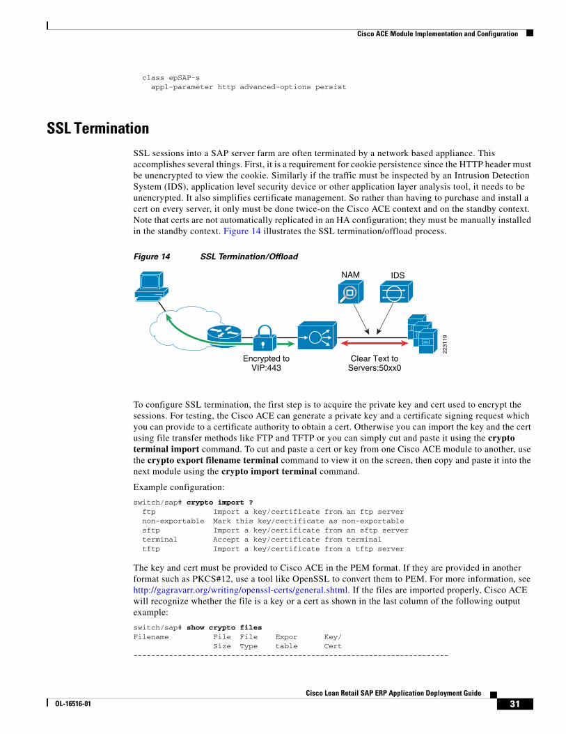
SSL TerminationSSL sessions into a SAP server farm are often terminated by a network based appliance. This accomplishes several things. First, it is a requirement for cookie persistence since the HTTP header must be unencrypted to view the cookie. Similarly if the traffic must be inspected by an Intrusion Detection System (IDS), application level security device or other application layer analysis tool, it needs to be unencrypted. It also simplifies certificate management. So rather than having to purchase and install a cert on every server, it only must be done twice-on the Cisco ACE context and on the standby context. Note that certs are not automatically replicated in an HA configuration; they must be manually installed in the standby context. Figure 14 illustrates the SSL termination/offload process.
Figure 14 SSL Termination/Offload
To configure SSL termination, the first step is to acquire the private key and cert used to encrypt the sessions. For testing, the Cisco ACE can generate a private key and a certificate signing request which you can provide to a certificate authority to obtain a cert. Otherwise you can import the key and the cert using file transfer methods like FTP and TFTP or you can simply cut and paste it using the crypto terminal import command. To cut and paste a cert or key from one Cisco ACE module to another, use the crypto export filename terminal command to view it on the screen, then copy and paste it into the next module using the crypto import terminal command.
Example configuration:
switch/sap# crypto import ? ftp Import a key/certificate from an ftp server non-exportable Mark this key/certificate as non-exportable sftp Import a key/certificate from an sftp server terminal Accept a key/certificate from terminal tftp Import a key/certificate from a tftp server
The key and cert must be provided to Cisco ACE in the PEM format. If they are provided in another format such as PKCS#12, use a tool like OpenSSL to convert them to PEM. For more information, see http://gagravarr.org/writing/openssl-certs/general.shtml. If the files are imported properly, Cisco ACE will recognize whether the file is a key or a cert as shown in the last column of the following output example:
switch/sap# show crypto filesFilename File File Expor Key/ Size Type table Cert-----------------------------------------------------------------------
NAM
Clear Text toServers:50xx0
Encrypted toVIP:443
IDS
2231
19
31Cisco Lean Retail SAP ERP Application Deployment Guide
OL-16516-01
Cisco ACE Module Implementation and Configuration
testkey.key 497 PEM Yes KEYSAPcert.cer 855 PEM Yes CERT
You can verify that the cert matches the key with the crypto verify command:
Cisco ACE-1/sap# crypto verify testkey.key SAPcert.cer Keypair in testkey.key matches certificate in SAPcert.cer.
Once the private key and cert are in place, create a proxy and attach it to the multi-match policy as follows:
ssl-proxy service sap key testkey.key cert SAPcert.cer policy-map multi-match SLB-policy class epSAP-s ssl-proxy server sap
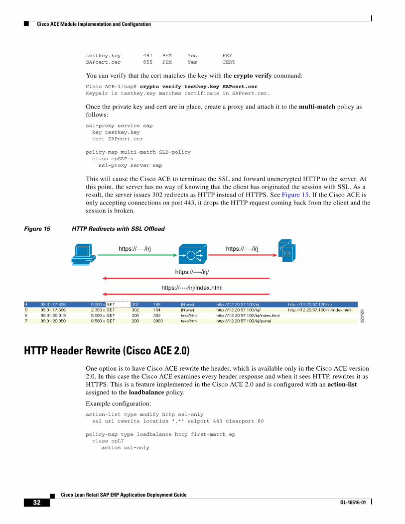
This will cause the Cisco ACE to terminate the SSL and forward unencrypted HTTP to the server. At this point, the server has no way of knowing that the client has originated the session with SSL. As a result, the server issues 302 redirects as HTTP instead of HTTPS. See Figure 15. If the Cisco ACE is only accepting connections on port 443, it drops the HTTP request coming back from the client and the session is broken.
Figure 15 HTTP Redirects with SSL Offload
HTTP Header Rewrite (Cisco ACE 2.0)One option is to have Cisco ACE rewrite the header, which is available only in the Cisco ACE version 2.0. In this case the Cisco ACE examines every header response and when it sees HTTP, rewrites it as HTTPS. This is a feature implemented in the Cisco ACE 2.0 and is configured with an action-list assigned to the loadbalance policy.
Example configuration:
action-list type modify http ssl-only ssl url rewrite location ".*" sslport 443 clearport 80
policy-map type loadbalance http first-match ep class epL7 action ssl-only
https://----/irj
2231
20
https://----/irj
https://----/irj/
https://----/irj/index.html
32Cisco Lean Retail SAP ERP Application Deployment Guide
OL-16516-01
Cisco ACE Module Implementation and Configuration
HTTP Header InsertA better approach that HTTP header rewrite is to take advantage of a custom header SAP has designed specifically for the SAP load-balancer doing offload—ClientProtocol. When the SAP EP sees this header with a value of HTTPS, it knows to use HTTPS for the redirect, rather than HTTP. This is explained at the following URL:
http://help.sap.com/saphelp_nw04s/helpdata/en/9a/53a2a4a45e244aa189c2b7065a0b78/content.htm.
The Cisco ACE adds this header (available in Cisco ACE version 1.x) when the insert-http command is enabled on the loadbalance policy.
Example configuration:
policy-map type loadbalance first-match EP-HTTPS class class-default insert-http ClientProtocol header-value "https"
Persistence RebalanceAnother feature that should be enabled for either of the header rewrite or header insert options is persistence rebalance. Without persistence rebalance, a Cisco ACE only performs the header rewrite/insert on the first request of the connection. If there are multiple redirects in a connection, some will get missed and the SAP server will still send HTTP redirects. When persistence rebalance is enabled, the header is inserted into every request. This is done by adding another line to the parameter-map already established for header parsing.
parameter-map type http persist set header-maxparse-length 4096 persistence-rebalance policy-map multi-match SLB-policy class epSAP-s appl-parameter http advanced-options persist
Redirect ServerIf the policy is to only accept SSL connections to the server farm, the question becomes what to do with client requests for HTTP. As was shown above, the SAP server itself may redirect the client to HTTP if it does not realize the session originated as HTTPS. But there could also be other scenarios. The client may not know that HTTPS is a requirement and simply originate the connection as HTTP. There have also been cases where HTTP redirects are built into scripts by the server. One way to address all of these situations is with a redirect server. This way, anytime a client attempts to connect with HTTP, Cisco ACE can itself send a redirect to the client using a redirect server. This is done by creating a special “redirect” rserver and associating it with a policy that matches the same VIP address on port 80. When a request comes in from the client using HTTP it matches the redirect policy. This policy resolves to the redirect server which sends the HTTPS 302 to the client. This serves as a last line of defense so that if for any other reason an HTTP request comes in, it is redirected to HTTPS. The essential piece is the definition of the redirect server:
rserver redirect anyHTTP webhost-redirection https://irj/portal 302 inservice
This rserver must then be setup in a server farm, match a port 80 VIP, and match a load balancing and multimatch policy as shown in the following example:
33Cisco Lean Retail SAP ERP Application Deployment Guide
OL-16516-01
Cisco ACE Module Implementation and Configuration
serverfarm host REDIRECT rserver anyHTTP inservice
class-map match-any HTTP-VIP match virtual-address 169.145.90.116 tcp eq www
policy-map type loadbalance first-match EP-HTTP-policy class class-default serverfarm REDIRECT
policy-map multi-match SAP-LB class HTTP-VIP loadbalance vip inservice loadbalance policy EP-HTTP-policy
Impact of TCP Reuse and SSL Termination on Server CPUWhen implementing SSL offload and TCP reuse together, server CPU utilization was improved. The amount of improvement increased with the transaction load. In the case of the DSL WAN, the transaction load was 16,000 transactions over a six-hour period and the CPU savings was 22 percent. When the transaction load was increased to 50,000 transactions the CPU savings was 50 percent. See Figure 16.
Figure 16 SAP EP CPU Utilization
Backend EncryptionIn some cases, the security policy requires that sessions are encrypted all the way to the server. With cookie persistence, however, the session must be decrypted to view the cookie. In this case Cisco ACE will decrypt the session, examine the header contents, make a server selection decision, and re-encrypt the session toward the server. See Figure 17.
34Cisco Lean Retail SAP ERP Application Deployment Guide
OL-16516-01
Cisco ACE Module Implementation and Configuration
Figure 17 SSL Offload with Backend Encryption
This uses most of the same configuration as SSL offload without the header insert and can be enabled by adding in a client SSL proxy facing the server. It is configured by defining a proxy and assigning it to the loadbalance policy.
Example configuration:
ssl-proxy service testsslclient
policy-map type loadbalance first-match EP-HTTPS class class-default no insert-http ClientProtocol header-value "https" ssl-proxy client testsslclient
SSL Reuse (Cisco ACE 2.0)With the Cisco ACE version 2.0, SSL reuse can help on both sides of the connection. On the client side, SSL reuse reduces delay in the WAN by eliminating the round trip delays required for the key exchange. On the server side, SSL reuse reduces the performance penalty of SSL encryption. Without SSL session ID reuse, there is a constant process of renegotiating SSL session IDs. The most costly piece of this negotiation is the key exchange process, which uses asymmetric encryption. Once the keys are exchanged, the data encryption is symmetric and requires little additional CPU. By reducing the amount of asymmetric encryption taking place, most of the performance penalty associated with SSL on the server can be eliminated. Testing showed server CPU reduced by 24 percent with SSL reuse enabled.
SSL session reuse is enabled in the Cisco ACE version 2.0 by creating an SSL parameter map and defining a timeout for the session-ID cache. Example configuration:
parameter-map type ssl sslparams session-cache timeout 600
This parameter map must be assigned to the SSL proxy facing the client and the SSL proxy facing the server. Example configuration:
ssl-proxy service testsslclient ssl advanced-options sslparams
ssl-proxy service sap key sap-private cert sap-cert ssl advanced-options sslparams
Use the show crypto session command to review the SSL session cache statistics. Example command output:
switch/sap# show crypto session SSL Session Cache Stats for Context ------------------
SSL Initiation
Encrypted toServers:50xx1
SSL Termination
Encrypted toVIP:443
2231
21
35Cisco Lean Retail SAP ERP Application Deployment Guide
OL-16516-01
Cisco ACE Module Implementation and Configuration
Number of Client Sessions 2Number of Server Sessions 4
TCP ReuseTCP reuse is used to reduce the amount of TCP connections to the server by sharing a pool of TCP connections across requests from multiple clients. See Figure 18. When a TCP connection is set up to the server, requests start to flow across it. For example, a Microsoft Internet Explorer (IE) browser will open up two TCP connections to the server and then load-balance all the individual object requests across those two connections. Without reuse, these TCP connections are only used by the client initiating the request.
Figure 18 TCP Connection Reuse
When TCP reuse is enabled, a TCP connection can be used by any client. When the Cisco ACE receives an object request from the client, it looks to see if there are any available TCP connections in the reuse pool and if one is available it uses it. If none are available, it sets up a new TCP connection. TCP connections are sent to the reuse pool when the server acknowledges a request, such as by returning a 200 OK. Until the time another request is sent across it, the TCP connection is available for reuse. The net effect is a reduction in the amount of memory required to service a given client load. If backend encryption is used, TCP reuse also improves server CPU performance by reducing the amount of encryption that needs to be done—fewer TCP connections translates into fewer SSL sessions.
TCP2
TCP3
2231
22
ACE-TCP2 Pool2
ACE-TCP1 Pool1
TCP1
36Cisco Lean Retail SAP ERP Application Deployment Guide
OL-16516-01
Cisco ACE Module Implementation and Configuration
In the testing with the Cisco ACE and the SAP EP, TCP reuse reduced the number of connections to EP by over 70 percent. See Figure 19.
Figure 19 TCP Reused with Cisco ACE and SAP EP
TCP reuse is configured by adding the server-conn reuse command to the same parameter map already used for header parsing and persistence rebalance:
parameter-map type http persist set header-maxparse-length 4096 persistence-rebalance server-conn reuse policy-map multi-match SLB-policy class epSAP-s appl-parameter http advanced-options persist
Source NAT for TCP Reuse
In order for TCP reuse to work properly, network address translation (NAT) is required on the client source IP address. In the example configuration that follows, a NAT pool is set up on the server VLAN interface. This NAT pool is activated when there is a match with the SAP-LB policy because of the nat dynamic command applied to the policy-map multi-match command. In this case, all traffic to the SSL-VIP with this policy will have the source IP address changed to 169.145.90.90.
Example configuration:
interface vlan 40 description server-EP nat-pool 123 169.145.90.90 169.145.90.90 netmask 255.255.255.255 patpolicy-map multi-match SLB-policy class SSL-VIP nat dynamic 123 vlan 201
37Cisco Lean Retail SAP ERP Application Deployment Guide
OL-16516-01
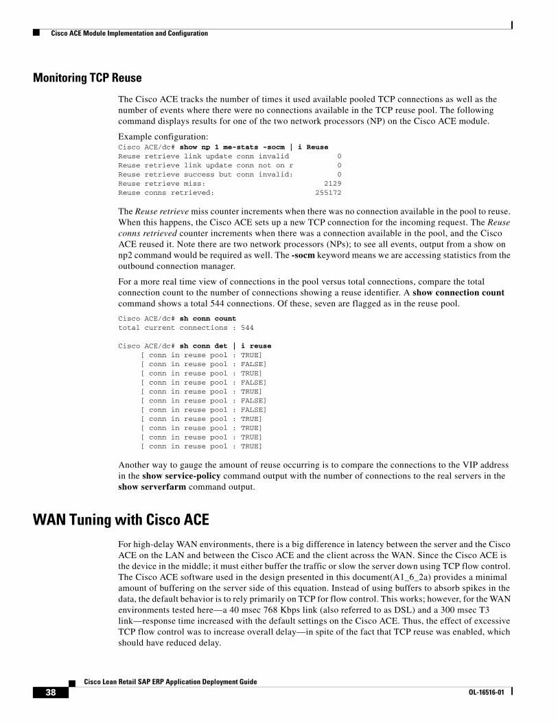
Cisco ACE Module Implementation and Configuration
Monitoring TCP Reuse
The Cisco ACE tracks the number of times it used available pooled TCP connections as well as the number of events where there were no connections available in the TCP reuse pool. The following command displays results for one of the two network processors (NP) on the Cisco ACE module.
Example configuration:Cisco ACE/dc# show np 1 me-stats -socm | i ReuseReuse retrieve link update conn invalid 0Reuse retrieve link update conn not on r 0Reuse retrieve success but conn invalid: 0Reuse retrieve miss: 2129Reuse conns retrieved: 255172
The Reuse retrieve miss counter increments when there was no connection available in the pool to reuse. When this happens, the Cisco ACE sets up a new TCP connection for the incoming request. The Reuse conns retrieved counter increments when there was a connection available in the pool, and the Cisco ACE reused it. Note there are two network processors (NPs); to see all events, output from a show on np2 command would be required as well. The -socm keyword means we are accessing statistics from the outbound connection manager.
For a more real time view of connections in the pool versus total connections, compare the total connection count to the number of connections showing a reuse identifier. A show connection count command shows a total 544 connections. Of these, seven are flagged as in the reuse pool.
Cisco ACE/dc# sh conn counttotal current connections : 544
Cisco ACE/dc# sh conn det | i reuse [ conn in reuse pool : TRUE] [ conn in reuse pool : FALSE] [ conn in reuse pool : TRUE] [ conn in reuse pool : FALSE] [ conn in reuse pool : TRUE] [ conn in reuse pool : FALSE] [ conn in reuse pool : FALSE] [ conn in reuse pool : TRUE] [ conn in reuse pool : TRUE] [ conn in reuse pool : TRUE] [ conn in reuse pool : TRUE]
Another way to gauge the amount of reuse occurring is to compare the connections to the VIP address in the show service-policy command output with the number of connections to the real servers in the show serverfarm command output.
WAN Tuning with Cisco ACEFor high-delay WAN environments, there is a big difference in latency between the server and the Cisco ACE on the LAN and between the Cisco ACE and the client across the WAN. Since the Cisco ACE is the device in the middle; it must either buffer the traffic or slow the server down using TCP flow control. The Cisco ACE software used in the design presented in this document(A1_6_2a) provides a minimal amount of buffering on the server side of this equation. Instead of using buffers to absorb spikes in the data, the default behavior is to rely primarily on TCP for flow control. This works; however, for the WAN environments tested here—a 40 msec 768 Kbps link (also referred to as DSL) and a 300 msec T3 link—response time increased with the default settings on the Cisco ACE. Thus, the effect of excessive TCP flow control was to increase overall delay—in spite of the fact that TCP reuse was enabled, which should have reduced delay.
38Cisco Lean Retail SAP ERP Application Deployment Guide
OL-16516-01
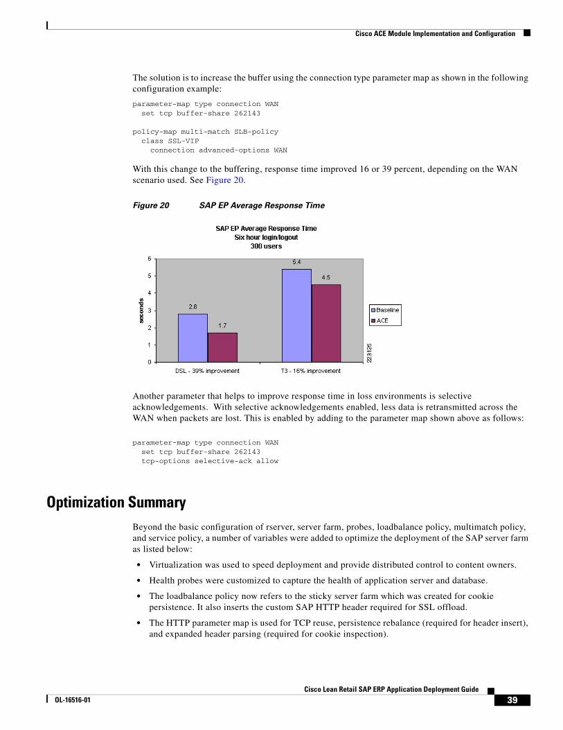
Cisco ACE Module Implementation and Configuration
The solution is to increase the buffer using the connection type parameter map as shown in the following configuration example:
parameter-map type connection WAN set tcp buffer-share 262143
policy-map multi-match SLB-policy class SSL-VIP connection advanced-options WAN
With this change to the buffering, response time improved 16 or 39 percent, depending on the WAN scenario used. See Figure 20.
Figure 20 SAP EP Average Response Time
Another parameter that helps to improve response time in loss environments is selective acknowledgements. With selective acknowledgements enabled, less data is retransmitted across the WAN when packets are lost. This is enabled by adding to the parameter map shown above as follows:
parameter-map type connection WAN set tcp buffer-share 262143 tcp-options selective-ack allow
Optimization SummaryBeyond the basic configuration of rserver, server farm, probes, loadbalance policy, multimatch policy, and service policy, a number of variables were added to optimize the deployment of the SAP server farm as listed below:
• Virtualization was used to speed deployment and provide distributed control to content owners.
• Health probes were customized to capture the health of application server and database.
• The loadbalance policy now refers to the sticky server farm which was created for cookie persistence. It also inserts the custom SAP HTTP header required for SSL offload.
• The HTTP parameter map is used for TCP reuse, persistence rebalance (required for header insert), and expanded header parsing (required for cookie inspection).
39Cisco Lean Retail SAP ERP Application Deployment Guide
OL-16516-01
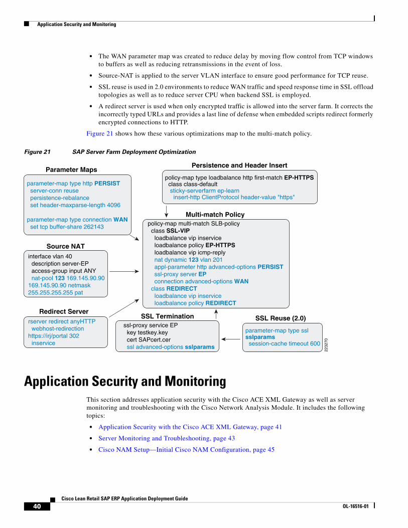
Application Security and Monitoring
• The WAN parameter map was created to reduce delay by moving flow control from TCP windows to buffers as well as reducing retransmissions in the event of loss.
• Source-NAT is applied to the server VLAN interface to ensure good performance for TCP reuse.
• SSL reuse is used in 2.0 environments to reduce WAN traffic and speed response time in SSL offload topologies as well as to reduce server CPU when backend SSL is employed.
• A redirect server is used when only encrypted traffic is allowed into the server farm. It corrects the incorrectly typed URLs and provides a last line of defense when embedded scripts redirect formerly encrypted connections to HTTP.
Figure 21 shows how these various optimizations map to the multi-match policy.
Figure 21 SAP Server Farm Deployment Optimization
Application Security and MonitoringThis section addresses application security with the Cisco ACE XML Gateway as well as server monitoring and troubleshooting with the Cisco Network Analysis Module. It includes the following topics:
• Application Security with the Cisco ACE XML Gateway, page 41
• Server Monitoring and Troubleshooting, page 43
• Cisco NAM Setup—Initial Cisco NAM Configuration, page 45
SSL Termination
parameter-map type http PERSISTserver-conn reusepersistence-rebalanceset header-maxparse-length 4096
parameter-map type connection WANset tcp buffer-share 262143
interface vlan 40description server-EPaccess-group input ANYnat-pool 123 169.145.90.90
169.145.90.90 netmask 255.255.255.255 pat
Parameter Maps
Source NAT
Multi-match Policypolicy-map multi-match SLB-policy
class SSL-VIP loadbalance vip inserviceloadbalance policy EP-HTTPS loadbalance vip icmp-replynat dynamic 123 vlan 201 appl-parameter http advanced-options PERSISTssl-proxy server EPconnection advanced-options WAN
class REDIRECT loadbalance vip inserviceloadbalance policy REDIRECT
ssl-proxy service EPkey testkey.keycert SAPcert.cerssl advanced-options sslparams
parameter-map type ssl sslparams
session-cache timeout 600
SSL Reuse (2.0)
policy-map type loadbalance http first-match EP-HTTPSclass class-defaultsticky-serverfarm ep-learn
insert-http ClientProtocol header-value "https"
Persistence and Header Insert
rserver redirect anyHTTP webhost-redirection
https://irj/portal 302inservice
Redirect Server
2232
70
40Cisco Lean Retail SAP ERP Application Deployment Guide
OL-16516-01
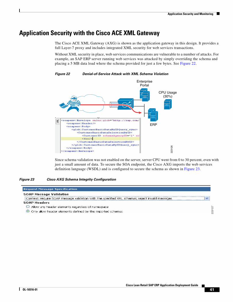
Application Security and Monitoring
Application Security with the Cisco ACE XML GatewayThe Cisco ACE XML Gateway (AXG) is shown as the application gateway in this design. It provides a full Layer-7 proxy and includes integrated XML security for web services transactions.
Without XML security in place, web services communications are vulnerable to a number of attacks. For example, an SAP ERP server running web services was attacked by simply overriding the schema and placing a 5 MB data load where the schema provided for just a few bytes. See Figure 22.
Figure 22 Denial-of-Service Attack with XML Schema Violation
Since schema validation was not enabled on the server, server CPU went from 0 to 30 percent, even with just a small amount of data. To secure the SOA endpoint, the Cisco AXG imports the web services definition language (WSDL) and is configured to secure the schema as shown in Figure 23.
Figure 23 Cisco AXG Schema Integrity Configuration
2231
26
ERP
CPU Usage(30%)
EnterprisePortal
41Cisco Lean Retail SAP ERP Application Deployment Guide
OL-16516-01
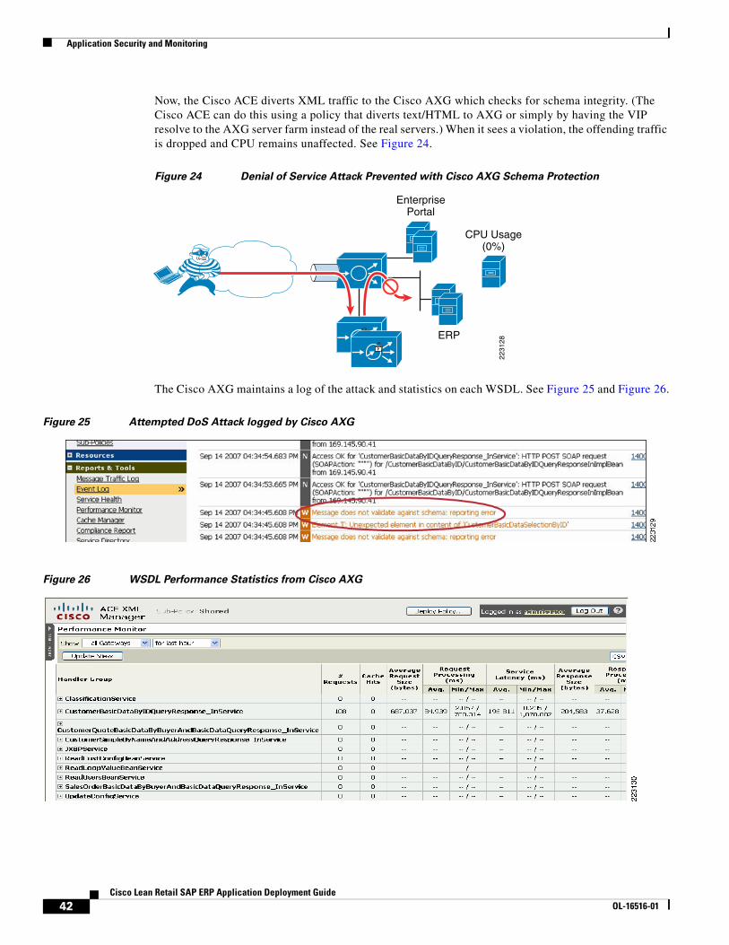
Application Security and Monitoring
Now, the Cisco ACE diverts XML traffic to the Cisco AXG which checks for schema integrity. (The Cisco ACE can do this using a policy that diverts text/HTML to AXG or simply by having the VIP resolve to the AXG server farm instead of the real servers.) When it sees a violation, the offending traffic is dropped and CPU remains unaffected. See Figure 24.
Figure 24 Denial of Service Attack Prevented with Cisco AXG Schema Protection
The Cisco AXG maintains a log of the attack and statistics on each WSDL. See Figure 25 and Figure 26.
Figure 25 Attempted DoS Attack logged by Cisco AXG
Figure 26 WSDL Performance Statistics from Cisco AXG
CPU Usage(0%)
2231
28
ERP
EnterprisePortal
42Cisco Lean Retail SAP ERP Application Deployment Guide
OL-16516-01
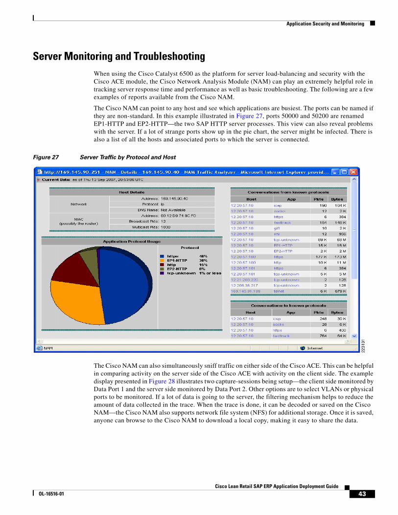
Application Security and Monitoring
Server Monitoring and TroubleshootingWhen using the Cisco Catalyst 6500 as the platform for server load-balancing and security with the Cisco ACE module, the Cisco Network Analysis Module (NAM) can play an extremely helpful role in tracking server response time and performance as well as basic troubleshooting. The following are a few examples of reports available from the Cisco NAM.
The Cisco NAM can point to any host and see which applications are busiest. The ports can be named if they are non-standard. In this example illustrated in Figure 27, ports 50000 and 50200 are renamed EP1-HTTP and EP2-HTTP—the two SAP HTTP server processes. This view can also reveal problems with the server. If a lot of strange ports show up in the pie chart, the server might be infected. There is also a list of all the hosts and associated ports to which the server is connected.
Figure 27 Server Traffic by Protocol and Host
The Cisco NAM can also simultaneously sniff traffic on either side of the Cisco ACE. This can be helpful in comparing activity on the server side of the Cisco ACE with activity on the client side. The example display presented in Figure 28 illustrates two capture-sessions being setup—the client side monitored by Data Port 1 and the server side monitored by Data Port 2. Other options are to select VLANs or physical ports to be monitored. If a lot of data is going to the server, the filtering mechanism helps to reduce the amount of data collected in the trace. When the trace is done, it can be decoded or saved on the Cisco NAM—the Cisco NAM also supports network file system (NFS) for additional storage. Once it is saved, anyone can browse to the Cisco NAM to download a local copy, making it easy to share the data.
43Cisco Lean Retail SAP ERP Application Deployment Guide
OL-16516-01
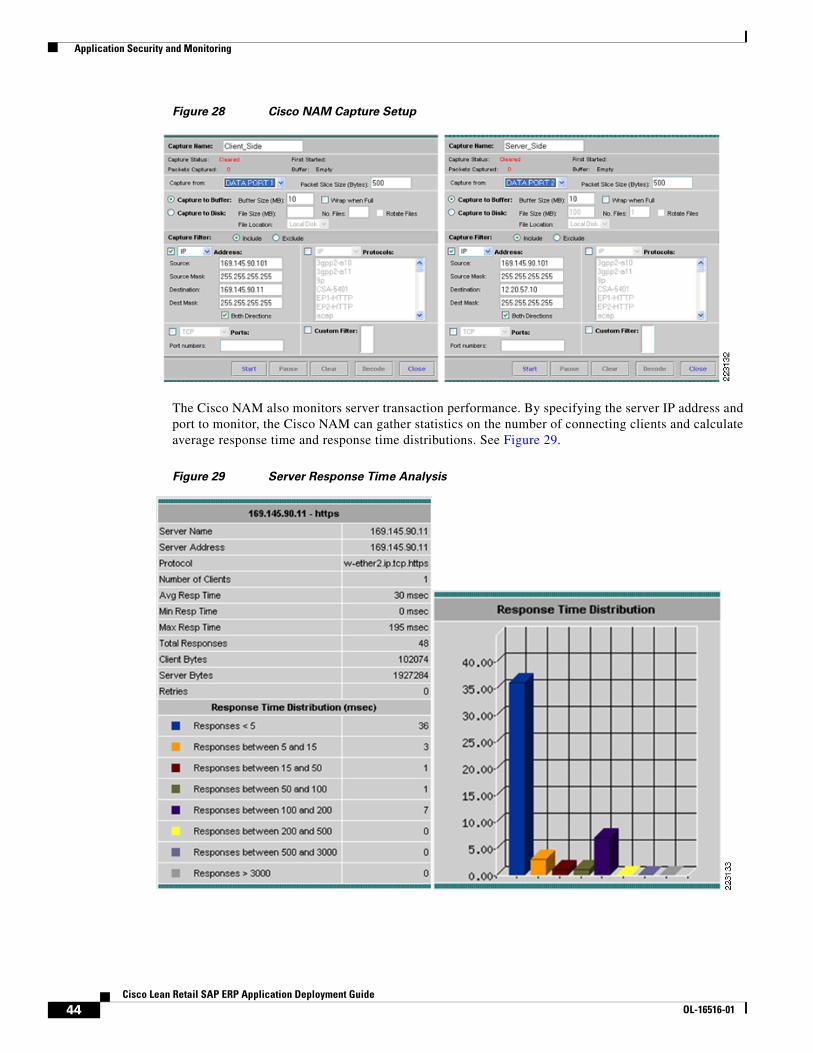
Application Security and Monitoring
Figure 28 Cisco NAM Capture Setup
The Cisco NAM also monitors server transaction performance. By specifying the server IP address and port to monitor, the Cisco NAM can gather statistics on the number of connecting clients and calculate average response time and response time distributions. See Figure 29.
Figure 29 Server Response Time Analysis
44Cisco Lean Retail SAP ERP Application Deployment Guide
OL-16516-01
Application Security and Monitoring
Cisco NAM Setup—Initial Cisco NAM ConfigurationThe first step in setting up the Cisco NAM is to input a basic configuration of IP address, default gateway, login information, and enable the HTTP server so you can browse to it. Also, if you want the Cisco NAM to resolve addresses to names in the reports, enter a DNS server. From the supervisor you connect to the Cisco NAM with the session command indicating the slot and a process number of 1. For example:
Session slot 2 proc 1
The default login is root/root:
ip address 17.2.14.132 255.255.255.0ip gateway 17.2.14.1ip nameserver 12.20.5.10ip http server enableEnabling HTTP server...
No web users are configured.Please enter a web administrator user name [admin]: New password: Confirm password: User admin added.Successfully enabled HTTP server.
Now that the Cisco NAM has an IP address and a default gateway and an active web server. Next, it must be assigned a VLAN on the Cisco Catalyst 6500. From configuration mode, input a VLAN for access to the NAM as well as the VLANs the Cisco NAM is allowed to see on its two data ports:
analysis module 2 management-port access-vlan 200analysis module 2 data-port 1 capture allowed-vlan 20analysis module 2 data-port 2 capture allowed-vlan 30
Finally, assign the ports or VLANs that will be assigned to the Cisco NAM using Switched Port Analyzer (SPAN):
monitor session 1 source vlan 20monitor session 1 destination analysis-module 2 data-port 1 monitor session 2 destination analysis-module 2 data-port 2 monitor session 2 source vlan 30
45Cisco Lean Retail SAP ERP Application Deployment Guide
OL-16516-01
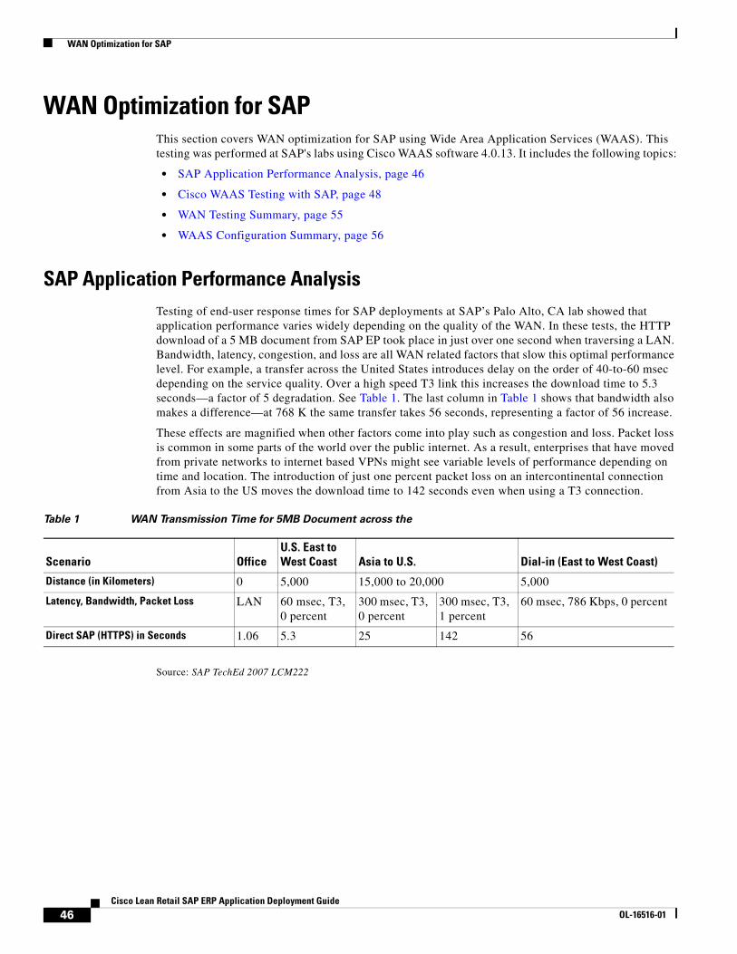
WAN Optimization for SAP
WAN Optimization for SAPThis section covers WAN optimization for SAP using Wide Area Application Services (WAAS). This testing was performed at SAP's labs using Cisco WAAS software 4.0.13. It includes the following topics:
• SAP Application Performance Analysis, page 46
• Cisco WAAS Testing with SAP, page 48
• WAN Testing Summary, page 55
• WAAS Configuration Summary, page 56
SAP Application Performance AnalysisTesting of end-user response times for SAP deployments at SAP’s Palo Alto, CA lab showed that application performance varies widely depending on the quality of the WAN. In these tests, the HTTP download of a 5 MB document from SAP EP took place in just over one second when traversing a LAN. Bandwidth, latency, congestion, and loss are all WAN related factors that slow this optimal performance level. For example, a transfer across the United States introduces delay on the order of 40-to-60 msec depending on the service quality. Over a high speed T3 link this increases the download time to 5.3 seconds—a factor of 5 degradation. See Table 1. The last column in Table 1 shows that bandwidth also makes a difference—at 768 K the same transfer takes 56 seconds, representing a factor of 56 increase.
These effects are magnified when other factors come into play such as congestion and loss. Packet loss is common in some parts of the world over the public internet. As a result, enterprises that have moved from private networks to internet based VPNs might see variable levels of performance depending on time and location. The introduction of just one percent packet loss on an intercontinental connection from Asia to the US moves the download time to 142 seconds even when using a T3 connection.
Source: SAP TechEd 2007 LCM222
Table 1 WAN Transmission Time for 5MB Document across the
Scenario OfficeU.S. East to West Coast Asia to U.S. Dial-in (East to West Coast)
Distance (in Kilometers) 0 5,000 15,000 to 20,000 5,000
Latency, Bandwidth, Packet Loss LAN 60 msec, T3, 0 percent
300 msec, T3, 0 percent
300 msec, T3, 1 percent
60 msec, 786 Kbps, 0 percent
Direct SAP (HTTPS) in Seconds 1.06 5.3 25 142 56
46Cisco Lean Retail SAP ERP Application Deployment Guide
OL-16516-01
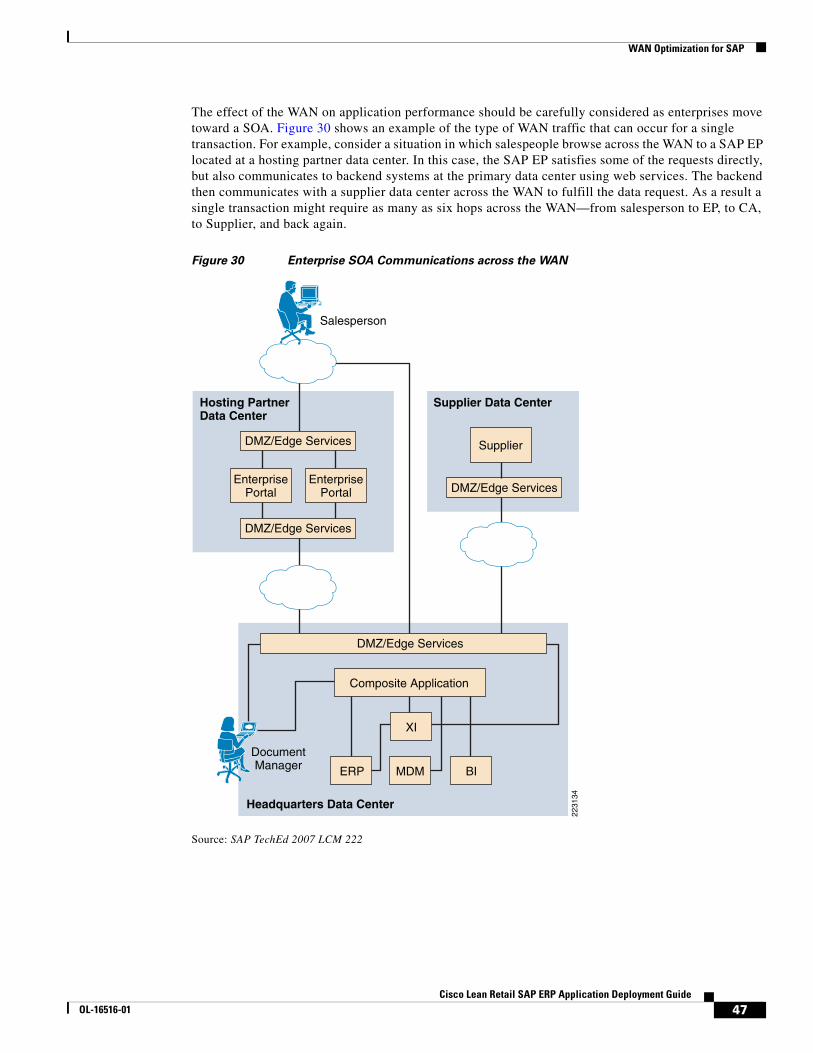
WAN Optimization for SAP
The effect of the WAN on application performance should be carefully considered as enterprises move toward a SOA. Figure 30 shows an example of the type of WAN traffic that can occur for a single transaction. For example, consider a situation in which salespeople browse across the WAN to a SAP EP located at a hosting partner data center. In this case, the SAP EP satisfies some of the requests directly, but also communicates to backend systems at the primary data center using web services. The backend then communicates with a supplier data center across the WAN to fulfill the data request. As a result a single transaction might require as many as six hops across the WAN—from salesperson to EP, to CA, to Supplier, and back again.
Figure 30 Enterprise SOA Communications across the WAN
Source: SAP TechEd 2007 LCM 222
2231
34
DMZ/Edge Services
DMZ/Edge Services
EnterprisePortal
EnterprisePortal
DocumentManager
Salesperson
Hosting PartnerData Center
DMZ/Edge Services
Composite Application
ERP
XI
Headquarters Data Center
BIMDM
DMZ/Edge Services
Supplier
Supplier Data Center
47Cisco Lean Retail SAP ERP Application Deployment Guide
OL-16516-01
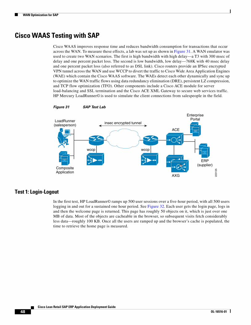
WAN Optimization for SAP
Cisco WAAS Testing with SAPCisco WAAS improves response time and reduces bandwidth consumption for transactions that occur across the WAN. To measure these effects, a lab was set up as shown in Figure 31. A WAN emulator was used to create two WAN scenarios. The first is high bandwidth with high delay—a T3 with 300 msec of delay and one percent packet loss. The second is low bandwidth, low delay—768K with 40 msec delay and one percent packet loss (also referred to as DSL link). Cisco routers provide an IPSec encrypted VPN tunnel across the WAN and use WCCP to divert the traffic to Cisco Wide Area Application Engines (WAE) which contain the Cisco WAAS software. The WAEs detect each other dynamically and sync up to optimize the WAN traffic flows using data redundancy elimination (DRE), persistent LZ compression, and TCP flow optimization (TFO). Other components include a Cisco ACE module for server load-balancing and SSL termination and the Cisco ACE XML Gateway to secure web services traffic. HP Mercury LoadRunner© is used to simulate the client connections from salespeople in the field.
Figure 31 SAP Test Lab
Test 1: Login-Logout
In the first test, HP LoadRunner© ramps up 500 user sessions over a five-hour period, with all 500 users logging in and out for a sustained one hour period. See Figure 32. Each user gets the login page, logs in and then the welcome page is returned. This page has roughly 50 objects on it, which is just over one MB of data. Most of the objects are cacheable in the browser, so subsequent visits fetch considerably less data—roughly 100 KB. Once all the users are ramped up and the browser’s cache is populated, the time to retrieve the home page is measured.
2231
35
ERP(supplier)
EnterprisePortal
ACE
wccp
insec encrypted tunnel
AXG
CompositeApplication
LoadRunner(salesperson)
wccp
48Cisco Lean Retail SAP ERP Application Deployment Guide
OL-16516-01
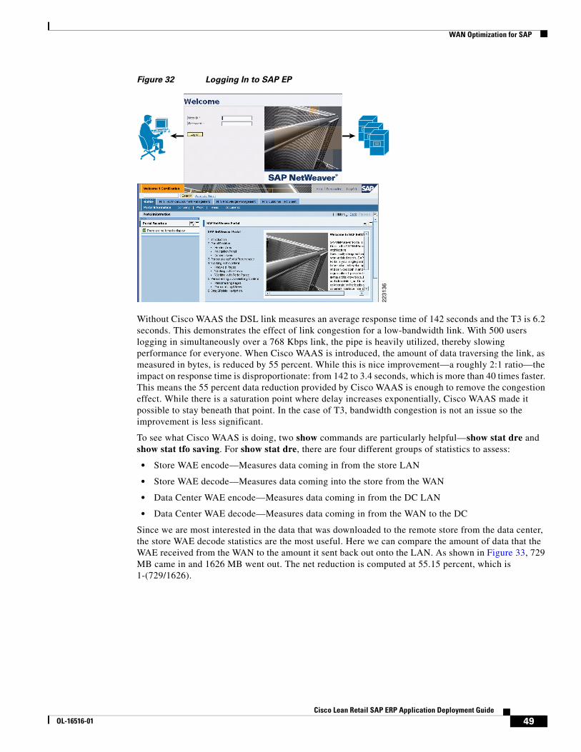
WAN Optimization for SAP
Figure 32 Logging In to SAP EP
Without Cisco WAAS the DSL link measures an average response time of 142 seconds and the T3 is 6.2 seconds. This demonstrates the effect of link congestion for a low-bandwidth link. With 500 users logging in simultaneously over a 768 Kbps link, the pipe is heavily utilized, thereby slowing performance for everyone. When Cisco WAAS is introduced, the amount of data traversing the link, as measured in bytes, is reduced by 55 percent. While this is nice improvement—a roughly 2:1 ratio—the impact on response time is disproportionate: from 142 to 3.4 seconds, which is more than 40 times faster. This means the 55 percent data reduction provided by Cisco WAAS is enough to remove the congestion effect. While there is a saturation point where delay increases exponentially, Cisco WAAS made it possible to stay beneath that point. In the case of T3, bandwidth congestion is not an issue so the improvement is less significant.
To see what Cisco WAAS is doing, two show commands are particularly helpful—show stat dre and show stat tfo saving. For show stat dre, there are four different groups of statistics to assess:
• Store WAE encode—Measures data coming in from the store LAN
• Store WAE decode—Measures data coming into the store from the WAN
• Data Center WAE encode—Measures data coming in from the DC LAN
• Data Center WAE decode—Measures data coming in from the WAN to the DC
Since we are most interested in the data that was downloaded to the remote store from the data center, the store WAE decode statistics are the most useful. Here we can compare the amount of data that the WAE received from the WAN to the amount it sent back out onto the LAN. As shown in Figure 33, 729 MB came in and 1626 MB went out. The net reduction is computed at 55.15 percent, which is 1-(729/1626).
2231
36
49Cisco Lean Retail SAP ERP Application Deployment Guide
OL-16516-01
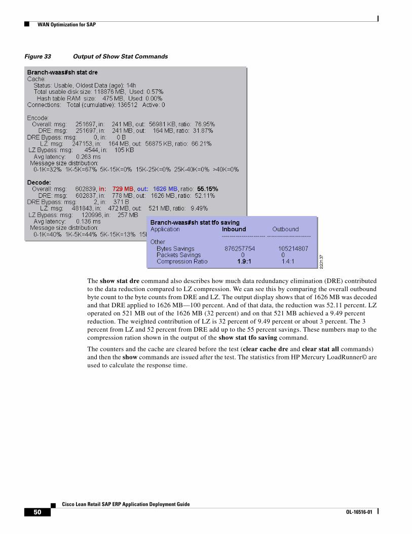
WAN Optimization for SAP
Figure 33 Output of Show Stat Commands
The show stat dre command also describes how much data redundancy elimination (DRE) contributed to the data reduction compared to LZ compression. We can see this by comparing the overall outbound byte count to the byte counts from DRE and LZ. The output display shows that of 1626 MB was decoded and that DRE applied to 1626 MB—100 percent. And of that data, the reduction was 52.11 percent. LZ operated on 521 MB out of the 1626 MB (32 percent) and on that 521 MB achieved a 9.49 percent reduction. The weighted contribution of LZ is 32 percent of 9.49 percent or about 3 percent. The 3 percent from LZ and 52 percent from DRE add up to the 55 percent savings. These numbers map to the compression ration shown in the output of the show stat tfo saving command.
The counters and the cache are cleared before the test (clear cache dre and clear stat all commands) and then the show commands are issued after the test. The statistics from HP Mercury LoadRunner© are used to calculate the response time.
50Cisco Lean Retail SAP ERP Application Deployment Guide
OL-16516-01
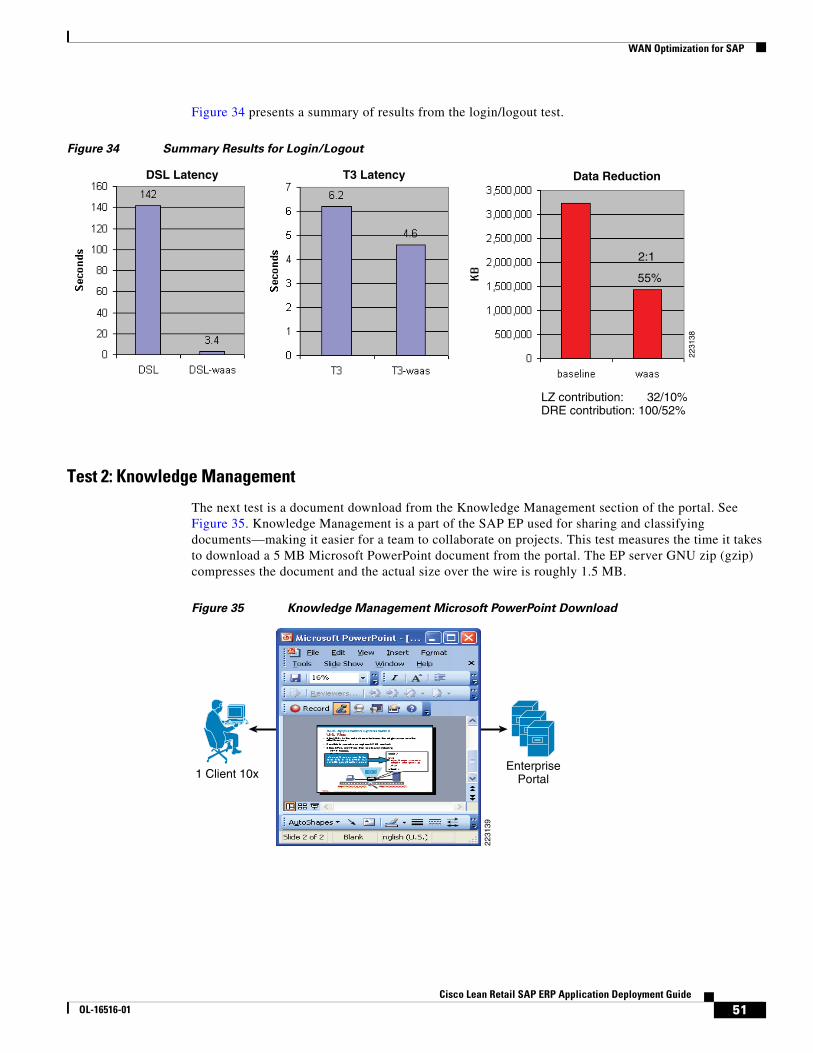
WAN Optimization for SAP
Figure 34 presents a summary of results from the login/logout test.
Figure 34 Summary Results for Login/Logout
Test 2: Knowledge Management
The next test is a document download from the Knowledge Management section of the portal. See Figure 35. Knowledge Management is a part of the SAP EP used for sharing and classifying documents—making it easier for a team to collaborate on projects. This test measures the time it takes to download a 5 MB Microsoft PowerPoint document from the portal. The EP server GNU zip (gzip) compresses the document and the actual size over the wire is roughly 1.5 MB.
Figure 35 Knowledge Management Microsoft PowerPoint Download
55%
2:1
LZ contribution: 32/10%DRE contribution: 100/52%
T3 LatencyDSL Latency Data Reduction
2231
38
2231
39
1 Client 10xEnterprise
Portal
51Cisco Lean Retail SAP ERP Application Deployment Guide
OL-16516-01
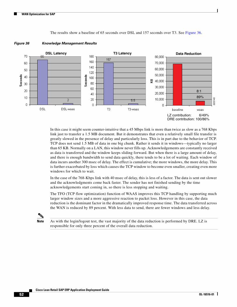
WAN Optimization for SAP
The results show a baseline of 65 seconds over DSL and 157 seconds over T3. See Figure 36.
Figure 36 Knowledge Management Results
In this case it might seem counter-intuitive that a 45 Mbps link is more than twice as slow as a 768 Kbps link just to transfer a 1.5 MB document. But it demonstrates that even a relatively small file transfer is greatly slowed in the presence of delay and particularly loss. This is in part due to the behavior of TCP. TCP does not send 1.5 MB of data in one big chunk. Rather it sends it in windows—typically no larger than 65 KB. Normally on a LAN, this window never fills up. Acknowledgements are constantly received as data is transferred and the window keeps sliding forward. But when there is a large amount of delay, and there is enough bandwidth to send data quickly, there tends to be a lot of waiting. Each window of data incurs another 300 msec of delay. The effect is cumulative; the more windows, the more delay. This is further exacerbated by loss which causes the TCP window to become even smaller, creating even more windows for which to wait.
In the case of the 768-Kbps link with 40 msec of delay, this is less of a factor. The data is sent out slower and the acknowledgments come back faster. The sender has not finished sending by the time acknowledgements start coming in, so there is less stopping and waiting.
The TFO (TCP flow optimization) function of WAAS improves this TCP handling by supporting much larger window sizes and a more aggressive reaction to packet loss. However in this case, the data reduction is the dominant factor in the dramatically improved response time. The data transferred across the WAN is reduced by 89 percent. With less data to send, there are fewer windows and less delay.
Note As with the login/logout test, the vast majority of the data reduction is performed by DRE. LZ is responsible for only three percent of the overall data reduction.
89%
8:1
LZ contribution: 6/49%DRE contribution: 100/86%
T3 LatencyDSL Latency Data Reduction
2231
40
52Cisco Lean Retail SAP ERP Application Deployment Guide
OL-16516-01
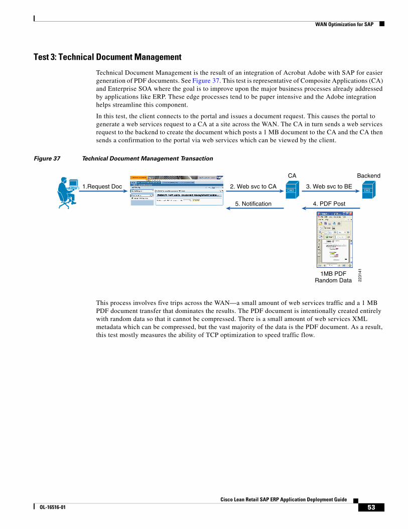
WAN Optimization for SAP
Test 3: Technical Document Management
Technical Document Management is the result of an integration of Acrobat Adobe with SAP for easier generation of PDF documents. See Figure 37. This test is representative of Composite Applications (CA) and Enterprise SOA where the goal is to improve upon the major business processes already addressed by applications like ERP. These edge processes tend to be paper intensive and the Adobe integration helps streamline this component.
In this test, the client connects to the portal and issues a document request. This causes the portal to generate a web services request to a CA at a site across the WAN. The CA in turn sends a web services request to the backend to create the document which posts a 1 MB document to the CA and the CA then sends a confirmation to the portal via web services which can be viewed by the client.
Figure 37 Technical Document Management Transaction
This process involves five trips across the WAN—a small amount of web services traffic and a 1 MB PDF document transfer that dominates the results. The PDF document is intentionally created entirely with random data so that it cannot be compressed. There is a small amount of web services XML metadata which can be compressed, but the vast majority of the data is the PDF document. As a result, this test mostly measures the ability of TCP optimization to speed traffic flow.
2231
41
CA
3. Web svc to BE
1MB PDFRandom Data
Backend
2. Web svc to CA1.Request Doc
4. PDF Post5. Notification
53Cisco Lean Retail SAP ERP Application Deployment Guide
OL-16516-01
WAN Optimization for SAP
In spite of a data reduction of only 26 percent (mostly by LZ in this case), the high-delay T3 download round trip time is improved by nearly 60 percent—from 126 to 51 seconds. As discussed above, the DSL link benefits very little from TFO and there is minimal improvement in this case. See Figure 38.
Figure 38 TDM Test Results
Test 4. Customer Fact Sheet
This test focuses entirely on web services XML transactions. See Figure 39. A request is made at the CA for a list of customers and associated accounts. This generates a web services request across the WAN to the ERP application server which responds initially with a list of 20 customers and 20 associated accounts. A total of 50 fact sheet requests are made, each larger by 20-to-40 customers with 40 accounts, 60x60, and so on, for a total of about 3 MB worth of data.
Figure 39 Customer Fact Sheet Transaction
26%
1.3:1
LZ contribution: 93/23%DRE contribution: 100/5%
Latency Data Reduction
2231
42
2231
43
50 Requestsfor CustomerFact Sheets
Comp SendsWeb Services
Request to ERP
ERP returnsCustomer FactSheet vis WebServices
CompositeApplication
ERP
54Cisco Lean Retail SAP ERP Application Deployment Guide
OL-16516-01
WAN Optimization for SAP
The customer names and account numbers are entirely random so they cannot be compressed. This focuses the test results on the ability to compress the XML metadata which surrounds each customer and account field. The amount of metadata exceeds the real customer data being transmitted, which is not uncommon for web services traffic. The test results show a significant data reduction of 77 percent (nearly 4:1). This reduction is entirely accounted for by LZ compression. See Figure 40.
Figure 40 Customer Fact Sheet Test Results
WAN Testing SummaryIn summary, these tests capture a range of SAP transaction types and the potential for improvement with WAAS is shown in each case. The first scenario highlights the problem of congestion and that even a moderate amount of data reduction can have a large impact on response times if it removes the congestion effect. The second scenario showed that WAAS can significantly reduce the bandwidth consumption and download time of compressed documents. The third test showed in a high delay / high bandwidth environment that even a completely randomized document can be downloaded much faster when TCP optimization is employed. The fourth test showed that web services XML traffic is ripe for WAN optimization and is considerably compressed with the LZ compression from WAAS. As a result, WAAS proved to be an effective tool for reducing bandwidth consumption and improving response time across the board with a variety of SAP traffic scenarios.
77%
3.8:1
LZ contribution: 100/77%DRE contribution: 100/0%
Latency Data Reduction
2231
44
55Cisco Lean Retail SAP ERP Application Deployment Guide
OL-16516-01
WAN Optimization for SAP
WAAS Configuration SummaryFigure 41 summarizes the key configuration requirements for the WAN optimization solution illustrated by the WAAS Central Manager, the data center WAE, and the data center WAN router.
Figure 41 WAAS Configuration Summary
Router WCCP Configuration Notes
Note the following about each of the configuration components shown in Figure 41:
• WAN router configurations
– The two WCCP processes 61 and 62 are enabled
– The WAE is on a dedicated interface where WCCP is excluded
– WCCP redirect commands are applied on the interface toward the servers
• WAE configurations
– Three WCCP commands to activate WCCP, the addresses refer to the adjacent router
ServerNetwork
ClientNetwork
0/0.92
Enable WCCPon UserInterface
Exclude WCCPto WAEInterface
0/0.962
0/0.93
WAN
WANRouterConfig
WAEConfig
CMConfig
hostname dc-waasdevice mode application-accelerator
primary-interface GigabitEthernet 1/0interface GigabitEthernet 1/0 ip address 169.145.93.93 255.255.255.0
ip default-gateway 169.145.93.1
ntp server 169.145.93.1
wccp router-list 1 169.145.92.1 169.145.93.1wccp tcp-promiscuous router-list-num 1wccp version 2
central-manager address 169.145.92.92cms enable
device mode central-managerinterface GigabitEthernet 1/0 ip address 169.145.92.92 255.255.255.0
ip default-gateway 169.145.92.1ntp server 169.145.93.1
hostname C2851ip wccp 61ip wccp 62
interface GigabitEthernet0/0.93description DC-wae
ip wccp redirect exclude in!interface GigabitEthernet0/0.962description server VLANip wccp 61 redirect inip wccp 62 redirect out
!ntp master 2
2232
71
56Cisco Lean Retail SAP ERP Application Deployment Guide
OL-16516-01
Summary and Conclusions
– The device mode designation is what makes it a WAE and not a central manager
– NTP, cms enable and the central manager address are for the central manager
– NTP is configured because unless all the WAEs and the central manager are in sync, the central manager will not function
• Central Manager configuration
– Minimal configuration that consist of just the device mode, NTP, and a basic IP setup.
Summary and ConclusionsThe Cisco Lean Retail SAP ERP design provides best practices and implementation guidance that optimizes ERP application availability, performance, and security while lowering application ownership costs.
Using a typical SAP portal deployment scenario, SAP-specific parameters are presented in a data center design which achieves efficiency and flexibility through virtualization and the integration of security with the server load-balancing functions in the Cisco ACE. In order to achieve a successful SAP deployment, there are several key configurations that are discussed.
The key parameters identified as important for optimizing performance in the tested environment include the following:
• Health monitoring probes
• Cookies for session persistence
• Persistence rebalance
• HTTP header parsing
• Custom SAP header insert for SSL offload
Other important components of the design include application security with the Cisco AXG and network monitoring with the Cisco NAM. Additionally, Cisco WAAS demonstrated the ability to significantly improve bandwidth utilization and response time of SAP across the WAN.
The Cisco Application Networking Services, featuring the Cisco Application Control Engine and Wide Area Application Services product families provides data center, retail store, and remote end-user application optimization services.
57Cisco Lean Retail SAP ERP Application Deployment Guide
OL-16516-01
Cisco Validated Design
Cisco Validated DesignThe Cisco Validated Design Program consists of systems and solutions designed, tested, and documented to facilitate faster, more reliable, and more predictable customer deployments. For more information visit www.cisco.com/go/validateddesigns.
ALL DESIGNS, SPECIFICATIONS, STATEMENTS, INFORMATION, AND RECOMMENDATIONS (COLLECTIVELY, "DESIGNS") IN THIS MANUAL ARE PRESENTED "AS IS," WITH ALL FAULTS. CISCO AND ITS SUPPLIERS DISCLAIM ALL WARRANTIES, INCLUDING, WITHOUT LIMITATION, THE WARRANTY OF MERCHANTABILITY, FITNESS FOR A PARTICULAR PURPOSE AND NONINFRINGEMENT OR ARISING FROM A COURSE OF DEALING, USAGE, OR TRADE PRACTICE. IN NO EVENT SHALL CISCO OR ITS SUPPLIERS BE LIABLE FOR ANY INDIRECT, SPECIAL, CONSEQUENTIAL, OR INCIDENTAL DAMAGES, INCLUDING, WITHOUT LIMITATION, LOST PROFITS OR LOSS OR DAMAGE TO DATA ARISING OUT OF THE USE OR INABILITY TO USE THE DESIGNS, EVEN IF CISCO OR ITS SUPPLIERS HAVE BEEN ADVISED OF THE POSSIBILITY OF SUCH DAMAGES.
THE DESIGNS ARE SUBJECT TO CHANGE WITHOUT NOTICE. USERS ARE SOLELY RESPONSIBLE FOR THEIR APPLICATION OF THE DESIGNS. THE DESIGNS DO NOT CONSTITUTE THE TECHNICAL OR OTHER PROFESSIONAL ADVICE OF CISCO, ITS SUPPLIERS OR PARTNERS. USERS SHOULD CONSULT THEIR OWN TECHNICAL ADVISORS BEFORE IMPLEMENTING THE DESIGNS. RESULTS MAY VARY DEPENDING ON FACTORS NOT TESTED BY CISCO.
CCDE, CCENT, Cisco Eos, Cisco Lumin, Cisco Nexus, Cisco StadiumVision, Cisco TelePresence, the Cisco logo, DCE, and Welcome to theHuman Network are trademarks; Changing the Way We Work, Live, Play, and Learn and Cisco Store are service marks; and Access Registrar,Aironet, AsyncOS, Bringing the Meeting To You, Catalyst, CCDA, CCDP, CCIE, CCIP, CCNA, CCNP, CCSP, CCVP, Cisco, the Cisco CertifiedInternetwork Expert logo, Cisco IOS, Cisco Press, Cisco Systems, Cisco Systems Capital, the Cisco Systems logo, Cisco Unity, CollaborationWithout Limitation, EtherFast, EtherSwitch, Event Center, Fast Step, Follow Me Browsing, FormShare, GigaDrive, HomeLink, Internet Quotient,IOS, iPhone, iQ Expertise, the iQ logo, iQ Net Readiness Scorecard, iQuick Study, IronPort, the IronPort logo, LightStream, Linksys, MediaTone,MeetingPlace, MeetingPlace Chime Sound, MGX, Networkers, Networking Academy, Network Registrar, PCNow, PIX, PowerPanels, ProConnect,ScriptShare, SenderBase, SMARTnet, Spectrum Expert, StackWise, The Fastest Way to Increase Your Internet Quotient, TransPath, WebEx, andthe WebEx logo are registered trademarks of Cisco Systems, Inc. and/or its affiliates in the United States and certain other countries.
All other trademarks mentioned in this document or Website are the property of their respective owners. The use of the word partner does not implya partnership relationship between Cisco and any other company. (0807R)
58Cisco Lean Retail SAP ERP Application Deployment Guide
OL-16516-01