ems electronic motor starters easy multifunctional · pdf fileeasy multifunctional safe ......
TRANSCRIPT
Easy MultifunctionalSafe
www.eaton.euEMSElectronic motor starters
BR047001.indd 1 21.03.13 11:51
2
Defining the future.
Trendsetting is simply another word for action. This is why it was only natural for renowned Eaton products such as our DIL contactors and PKZ motor-protective circuit-breakers to be further developed and expanded on.
The result is the new series of PKE motor protection systems with electronic wide-range overload protection for state-of-the-art systems intended to increase machine availability above all.
Motor start from the tiniest
space.
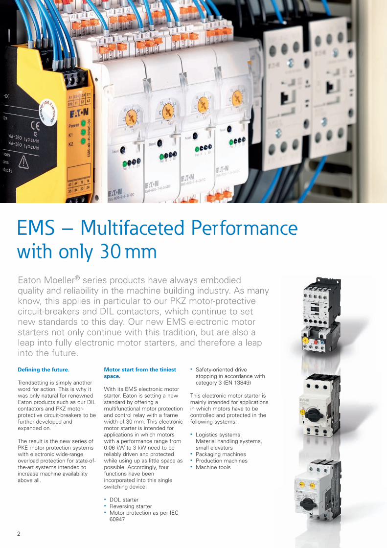
With its EMS electronic motor starter, Eaton is setting a new standard by offering a multifunctional motor protection and control relay with a frame width of 30 mm. This electronic motor starter is intended for applications in which motors with a performance range from 0.06 kW to 3 kW need to be reliably driven and protected while using up as little space as possible. Accordingly, four functions have been incorporated into this single switching device:
DOL starter Reversing starter Motor protection as per IEC
60947
Safety-oriented drive stopping in accordance with category 3 (EN 13849)
This electronic motor starter is mainly intended for applications in which motors have to be controlled and protected in the following systems:
Logistics systems Material handling systems, small elevators Packaging machines Production machines Machine tools
Eaton Moeller® series products have always embodied quality and reliability in the machine building industry. As many know, this applies in particular to our PKZ motor-protective circuit-breakers and DIL contactors, which continue to set new standards to this day. Our new EMS electronic motor starters not only continue with this tradition, but are also a leap into fully electronic motor starters, and therefore a leap into the future.
EMS – Multifaceted Performancewith only 30 mm
BR047001.indd 2 21.03.13 11:51
3
L1 L2 L3
M
1 2 3 4 5 6 7 8 9 10
1
10
100
1000
40
20
60
30
400
200
600
300
4
2
6
3
0.40.6
0.30.2
0
10 A
10
Class 10 AClass 10
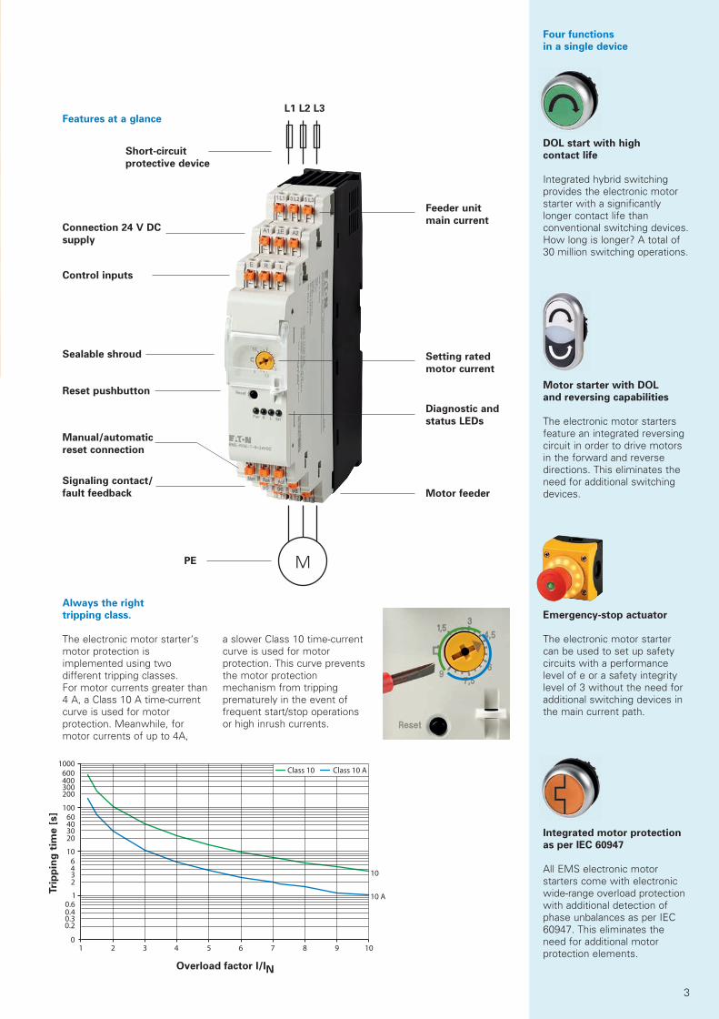
Always the right
tripping class.
The electronic motor starter‘s motor protection is implemented using two different tripping classes. For motor currents greater than 4 A, a Class 10 A time-current curve is used for motor protection. Meanwhile, for motor currents of up to 4A,
a slower Class 10 time-current curve is used for motor protection. This curve prevents the motor protection mechanism from tripping prematurely in the event of frequent start/stop operations or high inrush currents.
Features at a glance
Short-circuit
protective device
Feeder unit
main current
Setting rated
motor current
Diagnostic and
status LEDs
Motor feeder
Connection 24 V DC
supply
Control inputs
Reset pushbutton
Overload factor I/IN
Tri
pp
ing
tim
e [
s]
Sealable shroud
Manual/automatic
reset connection
Signaling contact/
fault feedback
PE
DOL start with high
contact life
Integrated hybrid switching provides the electronic motor starter with a significantly longer contact life than conventional switching devices. How long is longer? A total of 30 million switching operations.
Four functions
in a single device
Motor starter with DOL
and reversing capabilities
The electronic motor starters feature an integrated reversing circuit in order to drive motors in the forward and reverse directions. This eliminates the need for additional switching devices.
Integrated motor protection
as per IEC 60947
All EMS electronic motor starters come with electronic wide-range overload protection with additional detection of phase unbalances as per IEC 60947. This eliminates the need for additional motor protection elements.
Emergency-stop actuator
The electronic motor starter can be used to set up safety circuits with a performancelevel of e or a safety integrity level of 3 without the need for additional switching devices in the main current path.
3
BR047001.indd 3 21.03.13 11:51
4
642
531
L3L2L1
3/N/PE ~50 Hz 400 V
M
3 ~
PE
EMS
F1, F2, F3
E R L
-S1
E-STOP -S1
Safety logic
11
21
12
22 1
31
4S
34
S1
2
S3
4
13
14
S3
3
S1
1
S3
3
23
24
33
34
EMS-ROS-...
Reset
-S1
E-STOP -S1
Safety logic
11
21
12
22 1
31
4S
34
S1
2
S3
4
13
14
S3
3
S1
1
S3
3
23
24
33
34
Reset
21
22
-Q3
-Q2
21
22
-Q1
-Q2-Q1
0 V
21
22
-Q3
51
52
-Q2
51
52
-Q1
A1
A2
A1
A2
A1
A2
K3
5
6
3
4
1
2K2
5
6
3
4
1
2
531
642
K1
555
6
3
4
1
2
F1, F2, F3
L3L2L1
3/N/PE ~50 Hz 400 V
F4
M
3 ~
PE
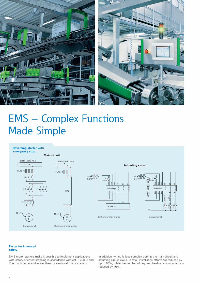
Faster for increased
safety
EMS motor starters make it possible to implement applications with safety-oriented stopping in accordance with cat. 3 / SIL 3 and PLe much faster and easier than conventional motor starters.
In addition, wiring is less complex both at the main circuit and actuating circuit levels. In total, installation efforts are reduced by up to 60%, while the number of required hardware components is reduced by 70%.
Conventional
Conventional Electronic motor starter
Electronic motor starter
Actuating circuit
Reversing starter with
emergency stop
Main circuit
EMS – Complex Functions Made Simple
BR047001.indd 4 21.03.13 11:51
5
100 %40 %
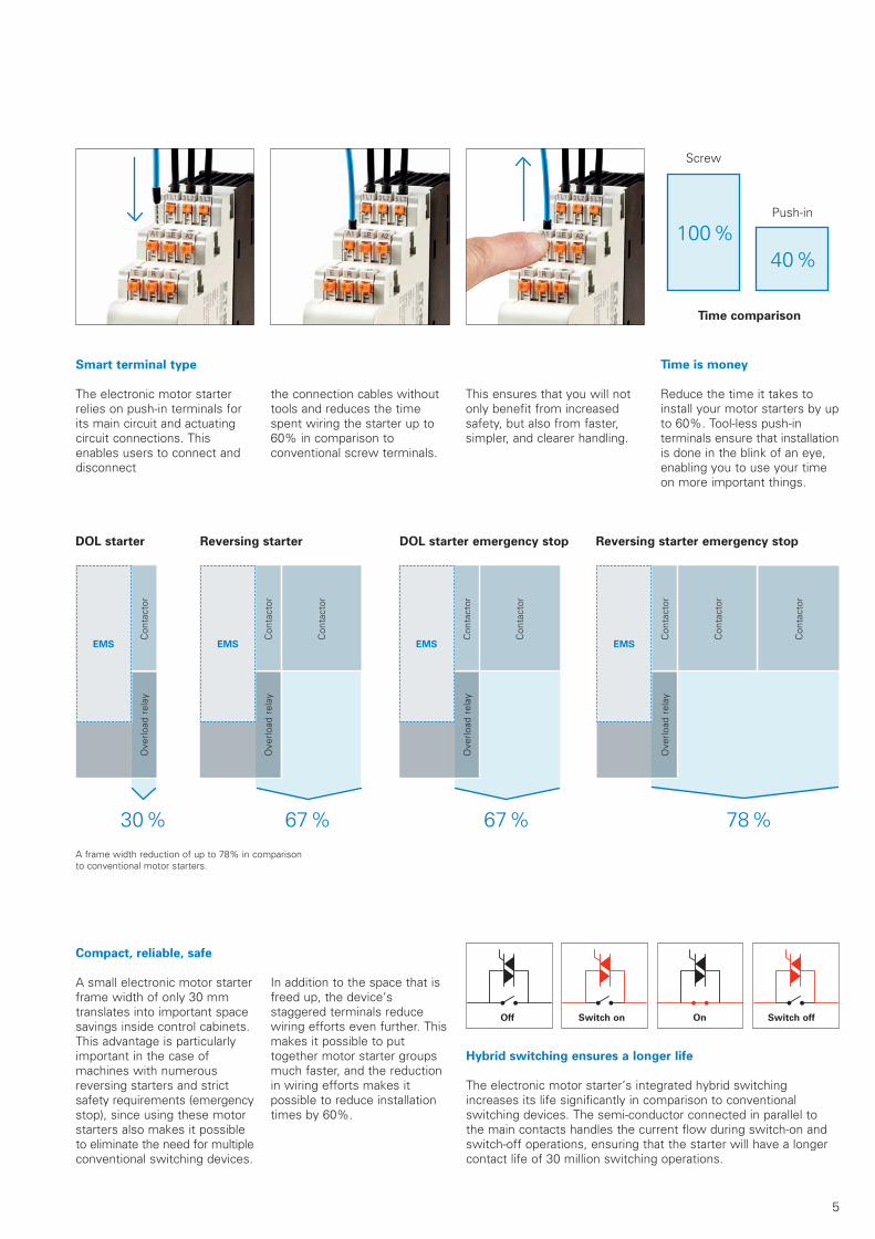
Smart terminal type
The electronic motor starter relies on push-in terminals for its main circuit and actuating circuit connections. This enables users to connect and disconnect
the connection cables without tools and reduces the time spent wiring the starter up to 60% in comparison to conventional screw terminals.
This ensures that you will not only benefit from increased safety, but also from faster, simpler, and clearer handling.
Time is money
Reduce the time it takes to install your motor starters by up to 60%. Tool-less push-in terminals ensure that installation is done in the blink of an eye, enabling you to use your time on more important things.
Time comparison
Screw
Push-in
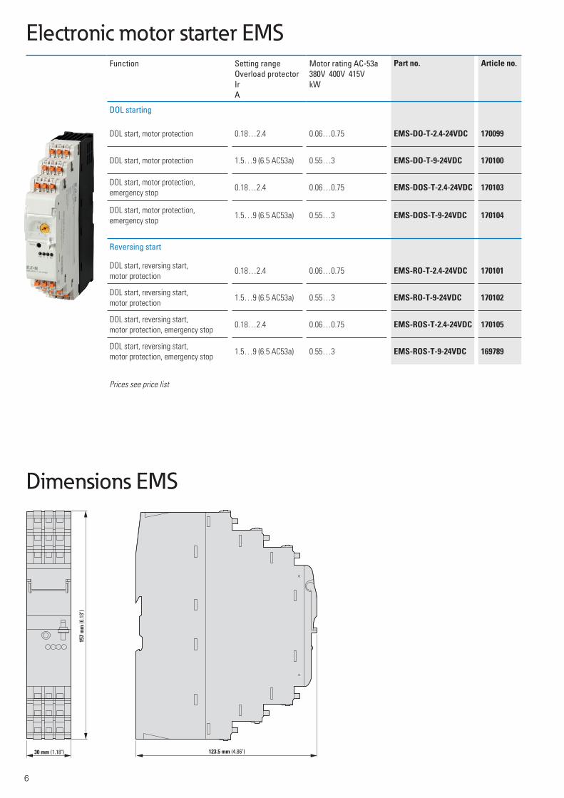
Compact, reliable, safe
A small electronic motor starter frame width of only 30 mm translates into important space savings inside control cabinets.This advantage is particularlyimportant in the case of machines with numerous reversing starters and strict safety requirements (emergency stop), since using these motor starters also makes it possible to eliminate the need for multiple conventional switching devices.
In addition to the space that is freed up, the device‘s staggered terminals reduce wiring efforts even further. This makes it possible to put together motor starter groups much faster, and the reduction in wiring efforts makes it possible to reduce installation times by 60%.
DOL starter Reversing starter DOL starter emergency stop Reversing starter emergency stop
Hybrid switching ensures a longer life
The electronic motor starter‘s integrated hybrid switching increases its life significantly in comparison to conventional switching devices. The semi-conductor connected in parallel to the main contacts handles the current flow during switch-on and switch-off operations, ensuring that the starter will have a longer contact life of 30 million switching operations.
A frame width reduction of up to 78% in comparison to conventional motor starters.
Off Switch on On Switch off
Con
tact
or
Con
tact
or
Con
tact
or
Con
tact
or
Ove
rload
rel
ay
Ove
rload
rel
ay
Ove
rload
rel
ay
Con
tact
orO
verlo
ad r
elay
Con
tact
orO
verlo
ad r
elay
EMS EMSEMS EMS
Con
tact
or
Con
tact
or
Con
tact
or
67 % 78 %30 % 67 %
BR047001.indd 5 21.03.13 11:51
6
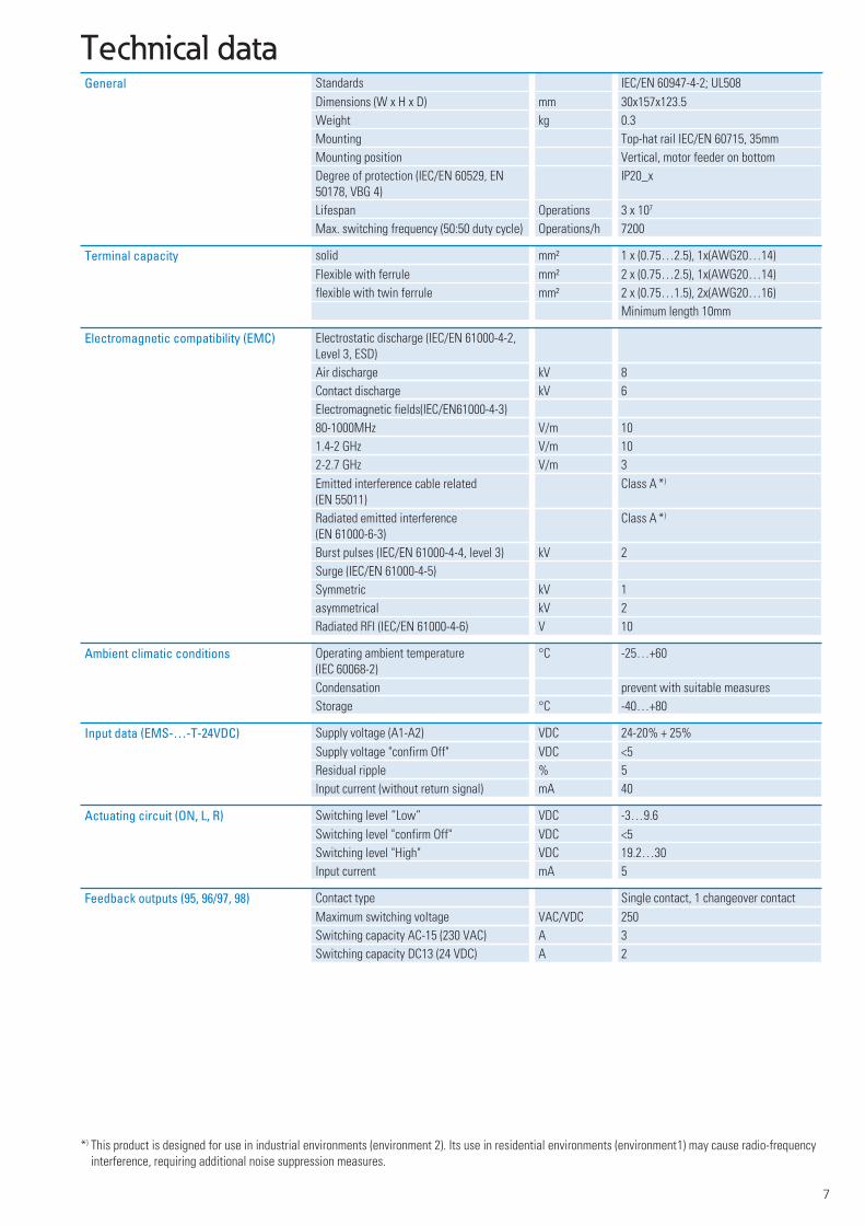
30 mm (1.18") 123.5 mm (4.86")
15
7 m
m (6.18")
Electronic motor starter EMS
Function Setting range Overload protectorIrA
Motor rating AC-53a380V 400V 415VkW
Part no. Article no.
DOL starting
DOL start, motor protection 0.18…2.4 0.06…0.75 EMS-DO-T-2.4-24VDC 170099
DOL start, motor protection 1.5…9 (6.5 AC53a) 0.55…3 EMS-DO-T-9-24VDC 170100
DOL start, motor protection, emergency stop
0.18…2.4 0.06…0.75 EMS-DOS-T-2.4-24VDC 170103
DOL start, motor protection, emergency stop
1.5…9 (6.5 AC53a) 0.55…3 EMS-DOS-T-9-24VDC 170104
Reversing start
DOL start, reversing start, motor protection
0.18…2.4 0.06…0.75 EMS-RO-T-2.4-24VDC 170101
DOL start, reversing start, motor protection
1.5…9 (6.5 AC53a) 0.55…3 EMS-RO-T-9-24VDC 170102
DOL start, reversing start, motor protection, emergency stop
0.18…2.4 0.06…0.75 EMS-ROS-T-2.4-24VDC 170105
DOL start, reversing start, motor protection, emergency stop
1.5…9 (6.5 AC53a) 0.55…3 EMS-ROS-T-9-24VDC 169789
Prices see price list
Dimensions EMS
7
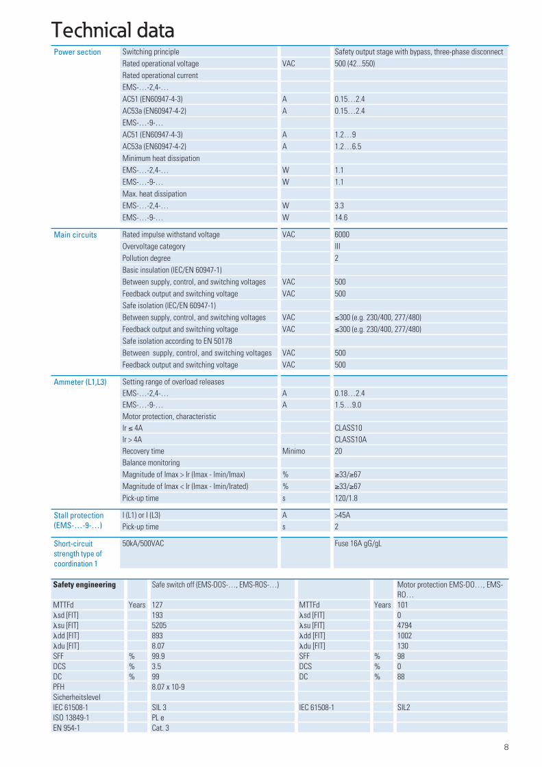
Technical dataGeneral Standards IEC/EN 60947-4-2; UL508
Dimensions (W x H x D) mm 30x157x123.5Weight kg 0.3Mounting Top-hat rail IEC/EN 60715, 35mmMounting position Vertical, motor feeder on bottomDegree of protection (IEC/EN 60529, EN 50178, VBG 4)
IP20_x
Lifespan Operations 3 x 10⁷
Max. switching frequency (50:50 duty cycle) Operations/h 7200
Terminal capacity solid mm² 1 x (0.75…2.5), 1x(AWG20…14)Flexible with ferrule mm² 2 x (0.75…2.5), 1x(AWG20…14)flexible with twin ferrule mm² 2 x (0.75…1.5), 2x(AWG20…16)
Minimum length 10mm
Electromagnetic compatibility (EMC) Electrostatic discharge (IEC/EN 61000-4-2, Level 3, ESD)Air discharge kV 8Contact discharge kV 6Electromagnetic fields(IEC/EN61000-4-3)80-1000MHz V/m 101.4-2 GHz V/m 10
2-2.7 GHz V/m 3Emitted interference cable related (EN 55011)
Class A *)
Radiated emitted interference (EN 61000-6-3)
Class A *)
Burst pulses (IEC/EN 61000-4-4, level 3) kV 2Surge (IEC/EN 61000-4-5)Symmetric kV 1asymmetrical kV 2Radiated RFI (IEC/EN 61000-4-6) V 10
Ambient climatic conditions Operating ambient temperature (IEC 60068-2)
°C -25…+60
Condensation prevent with suitable measuresStorage °C -40…+80
Input data (EMS-…-T-24VDC) Supply voltage (A1-A2) VDC 24-20% + 25%Supply voltage "confirm Off" VDC <5Residual ripple % 5Input current (without return signal) mA 40
Actuating circuit (ON, L, R) Switching level ”Low” VDC -3…9.6Switching level "confirm Off" VDC <5Switching level "High" VDC 19.2…30Input current mA 5
Feedback outputs (95, 96/97, 98) Contact type Single contact, 1 changeover contactMaximum switching voltage VAC/VDC 250Switching capacity AC-15 (230 VAC) A 3Switching capacity DC13 (24 VDC) A 2
*) This product is designed for use in industrial environments (environment 2). Its use in residential environments (environment 1) may cause radio-frequency interference, requiring additional noise suppression measures.
BR047001.indd 7 21.03.13 11:51
8
Technical dataPower section Switching principle Safety output stage with bypass, three-phase disconnect
Rated operational voltage VAC 500 (42...550)Rated operational currentEMS-…-2,4-…AC51 (EN60947-4-3) A 0.15…2.4AC53a (EN60947-4-2) A 0.15…2.4EMS-…-9-…AC51 (EN60947-4-3) A 1.2…9AC53a (EN60947-4-2) A 1.2…6.5Minimum heat dissipationEMS-…-2,4-… W 1.1EMS-…-9-… W 1.1Max. heat dissipationEMS-…-2,4-… W 3.3EMS-…-9-… W 14.6
Main circuits Rated impulse withstand voltage VAC 6000Overvoltage category IIIPollution degree 2Basic insulation (IEC/EN 60947-1)Between supply, control, and switching voltages VAC 500Feedback output and switching voltage VAC 500Safe isolation (IEC/EN 60947-1)Between supply, control, and switching voltages VAC ≤300 (e.g. 230/400, 277/480)Feedback output and switching voltage VAC ≤300 (e.g. 230/400, 277/480)Safe isolation according to EN 50178Between supply, control, and switching voltages VAC 500Feedback output and switching voltage VAC 500
Ammeter (L1,L3) Setting range of overload releasesEMS-…-2,4-… A 0.18…2.4EMS-…-9-… A 1.5…9.0Motor protection, characteristicIr ≤ 4A CLASS10Ir > 4A CLASS10ARecovery time Minimo 20Balance monitoringMagnitude of Imax > Ir (Imax - Imin/Imax) % ≥33/≥67Magnitude of Imax < Ir (Imax - Imin/Irated) % ≥33/≥67Pick-up time s 120/1.8
Stall protection (EMS-…-9-…)
I (L1) or I (L3) A >45APick-up time s 2
Short-circuit strength type of coordination 1
50kA/500VAC Fuse 16A gG/gL
Safety engineering Safe switch off (EMS-DOS-…, EMS-ROS-…) Motor protection EMS-DO…, EMS-RO…
MTTFd Years 127 MTTFd Years 101�sd [FIT] 193 �sd [FIT] 0�su [FIT] 5205 �su [FIT] 4794�dd [FIT] 893 �dd [FIT] 1002�du [FIT] 8.07 �du [FIT] 130SFF % 99.9 SFF % 98DCS % 3.5 DCS % 0DC % 99 DC % 88PFH 8.07 x 10⁻⁹SicherheitslevelIEC 61508-1 SIL 3 IEC 61508-1 SIL2ISO 13849-1 PL eEN 954-1 Cat. 3
BR047001.indd 8 21.03.13 11:51
9
TA [°C]0 10 20 30 40 50 60
6
8
0
4
2
9
7
5
3
1
IL [A]
③
②
①
[s]
1 2 3 4 5 6 7 8 9 10 I / In
1
10
100
1000
6040
3020
600400300200
64
32
0.60.4
0.30.2
0
10
[s]
1 2 3 4 5 6 7 8 9 10 I / In
1
10
100
1000
6040
3020
600400300200
64
32
0.60.4
0.30.2
0
10 A
EMS-…-9-…(Ir > 4A)
EMS-…-2,4-…EMS-…-9-…(Ir ≤ 4A)
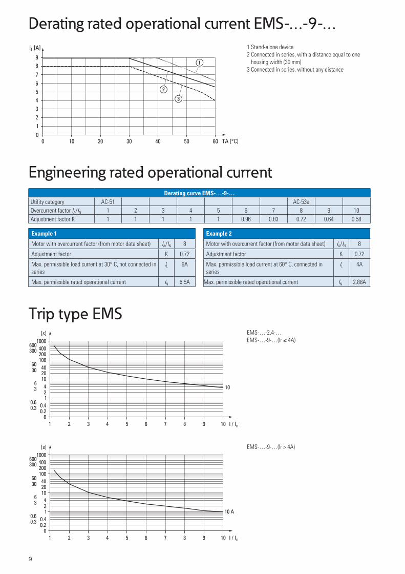
Derating rated operational current EMS-…-9-…
Trip type EMS
1 Stand-alone device2 Connected in series, with a distance equal to one
housing width (30 mm)3 Connected in series, without any distance
Engineering rated operational currentDerating curve EMS-…-9-…
Utility category AC-51 AC-53aOvercurrent factor IA/IN 1 2 3 4 5 6 7 8 9 10Adjustment factor K 1 1 1 1 1 0.96 0.83 0.72 0.64 0.58
Example 1
Motor with overcurrent factor (from motor data sheet) IA/IN 8
Adjustment factor K 0.72
Max. permissible load current at 30° C, not connected in series
IL 9A
Max. permissible rated operational current IN 6.5A
Example 2
Motor with overcurrent factor (from motor data sheet) IA/IN 8
Adjustment factor K 0.72
Max. permissible load current at 60° C, connected in series
IL 4A
Max. permissible rated operational current IN 2.88A
BR047001.indd 9 21.03.13 11:51

Eaton is dedicated to ensuring that reliable, efficient and safe power is available when it’s needed most. With unparalleled knowledge of electrical power management across industries, experts at Eaton deliver customized, integrated solutions to solve our customers’ most critical challenges.
Our focus is on delivering the right solution for the application. But, decision makers demand more than just innovative products. They turn to Eaton for an unwavering commitment to personal support that makes customer success a top priority. For more information, visit www.eaton.com/electrical.
To contact an Eaton salesperson orlocal distributor/agent, please visitwww.eaton.eu/electrical/customersupport
Changes to the products, to the information contained in this document, and to prices are reserved; so are errors and omissions. Only order confirmations and technical documenta-tion by Eaton is binding. Photos and pictures also do not warrant a specific layout or functiona-lity. Their use in whatever form is subject to prior approval by Eaton. The same applies to Trademarks (especially Eaton, Moeller, Cutler-Hammer). The Terms and Conditions of Eaton apply, as referenced on Eaton internet pages and Eaton order confirmations.
Eaton is a registered trademark of Eaton Corporation
All other trademarks are property of their respective owners.
SmartWire-DT® is a registered trademark of Eaton Corporation.
Eaton Industries GmbH
Hein-Moeller-Str. 7–11D-53115 B onn / Germany
© 2013 by Eaton CorporationAll rights reservedPrinted in Germany 03/13Publication No.: BR034001enip March 2013Article No.: 171852
BR047001.indd 10 21.03.13 11:51