grit characterization and optimal grit removal … ·...
TRANSCRIPT
Andoh, 2015: Grit Characterization and Optimal Grit Removal using the HeadCell® Device Page 1 of 20
Grit Characterization and Optimal Grit Removal Using the HeadCell® Device Robert Y.G. Andoh 1,*
1 AWD Consult Inc., 32 Vista Drive, South Portland, ME 04106, USA
*Author to whom correspondence should be addressed; E-Mail: [email protected].: +1 207-450-3670; Fax: +1 207-799-5846.
Abstract: Grit capture and removal from wastewater streams has increasingly become a critical process stage in wastewater treatment; particularly with the advent of advanced treatment processes such as membrane bio-reactors and other high-intensity and high-efficiency processes (e.g. fine bubble diffuser systems) that are subject to fouling and performance degradation if grit and other inert solids are not removed effectively. Grit has a tendency to accumulate downstream in basins and digester tanks causing operational challenges. Grit systems have traditionally been designed for a capture cut-point of 212-micron inert solids of an assumed specific gravity of 2650 kg/m3 (or relative density of 2.65). Experience of the operation of traditional grit removal systems has shown that significant carry over of grit occurs at wastewater treatment plants leading to its accumulation in downstream process stages and resulting in operational challenges. The paper assesses the characteristics of grit observed at a number of wastewater treatment sites in the US and Canada highlighting observed regional variations that may be attributed to local sub-soil characteristics and practices such as winter gritting of roads and highways. The analysis suggests that to achieve greater than 95 capture of entrained grit, grit removal systems should be designed to a finer target cut point of less than 106 microns. For most sites where no prior grit characterization information is available, a system designed to a 75-micron cut point should ensure adequate and appropriate levels of grit capture. The paper also reviews a number of case examples of the use of a high-efficiency grit removal system such as the HeadCell® for effective grit capture; highlighting its small footprint advantages and efficacy down to the 75-micron particle size. It concludes by recommending that there is the need to amend design practice to target grit below the 106 micron cut point to avoid the operational challenges observed at facilities mostly designed on the traditional 212-micron criterion.
Keywords: grit; characteristics; cut-point; particle size distribution; regional variation; device efficiency; North America
Andoh, 2015: Grit Characterization and Optimal Grit Removal using the HeadCell® Device Page 2 of 20
1. Introduction
Conventional grit removal and control at wastewater treatment plants has involved the removal ofthe heavier inert inorganic solids such as sand, gravel, silt, eggshells, metal filings, and other similar materials by settling. Settling is usually accomplished by reducing the velocity of the incoming wastewater enough to allow the heavier inert solids to settle, while allowing the lighter, organic materials to be transported into the subsequent wastewater treatment process stages.
Grit removal has typically been achieved by using a larger chamber or wide channel where the velocity of the water is simply reduced to facilitate the settling by gravity of the grit and other heavier inert solids. The perceived wisdom being that as long as the flow velocity is controlled in the range of 0.7 to 1.4 fps (0.2 to 0.4 m/s), a gravity grit removal process will remain effective.
Until relatively recently, the importance and relevance of grit source identification, its characterization and how this may impact on the efficacy of a grit removal system has often been overlooked leading to major equipment problems and excessive energy consumption at wastewater treatment plants. Wastewater treatment plants are generally equipped with preliminary treatment units such as screens and grit removal processes at their front-end to prevent downstream equipment fouling and damage; to reduce excessive wear on pumps, and to minimize loss of treatment capacity due to sand grit and other inert solids accumulation. These preliminary wastewater treatment systems have often not been optimally designed taking into account the nature and characteristics of the grit and other inert solids arriving at treatment works sites.
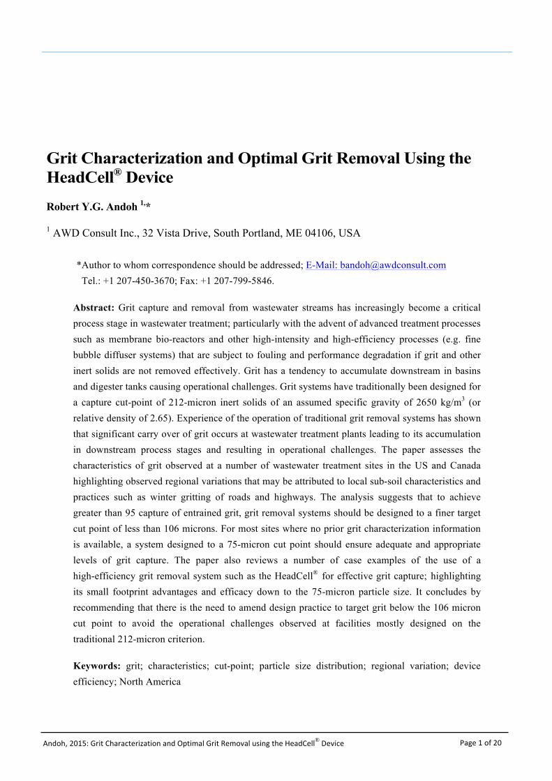
Grit systems have traditionally been designed to capture grit greater than 212 microns in particle size with a specific gravity of 2650 kg/m3 (or relative density of 2.65) (Metcalf & Eddy, et al., 2003). Experience of the operation of traditional grit removal systems has shown that significant carry over of grit is occurring at wastewater treatment plants leading to its accumulation in downstream process stages (EPA, 1987). Figure 1 shows examples of conventional grit removal equipment and design guides.
Figure 1
Andoh, 2015: Grit Characterization and Optimal Grit Removal using the HeadCell® Device Page 3 of 20
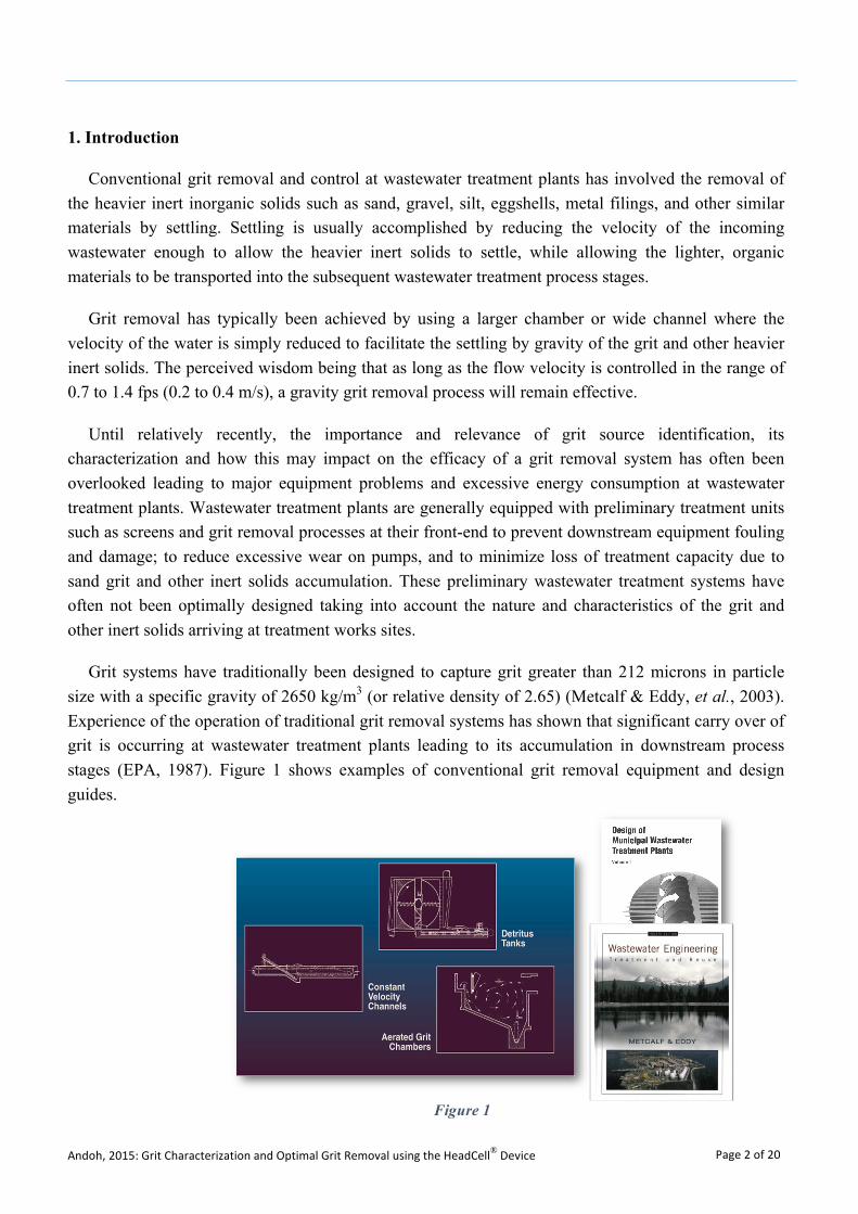
Figure 2 shows examples of the kinds of operational challenges encountered at wastewater treatment plants that have been designed to the conventional design practice. Grit not captured at the preliminary treatment stage tends to accumulate in regions of low velocities (e.g. primary tanks, aeration lanes, digesters, SBRs etc.).
This paper assesses data obtained on the particle size distributions of endemic grit encountered at various sites in North America showing that for most sites, at least 25 – 50% of the grit has a particle size less than 212 microns. This would account for the poor performance observed for grit removal equipment designed on the basis of the traditional 212-micron cut-point criteria.
Problems with grit and other inert solids control and removal have not been well understood and frequently the associated equipment are neither optimally designed nor properly maintained. When maintenance is neglected, treatment plant performance is adversely impacted, energy and maintenance costs significantly increase, and equipment failures occur more frequently.
The analysis of grit characteristics is presented in subsequent sections and shows that though grit characteristics appear to vary from site to site and observations suggest discernable regional variations; to obtain grit removal efficiencies above 95%, the target cut-point for grit facility designs should be less than 106 microns. The data suggests that for most sites where no prior grit characterization information is available, a system designed to a 75-micron cut point should be a safe design.
The paper further reviews a number of case examples of the use of a high-efficiency grit removal systems such as the HeadCell® for effective fine grit capture down to the 75-micron cut point and concludes by recommending the need to amend design practice to target grit below the 106 micron cut point to avoid the operational challenges observed.
Figure 2
Andoh, 2015: Grit Characterization and Optimal Grit Removal using the HeadCell® Device Page 4 of 20
2. Grit Characteristics
2.1. Data from North American Sites
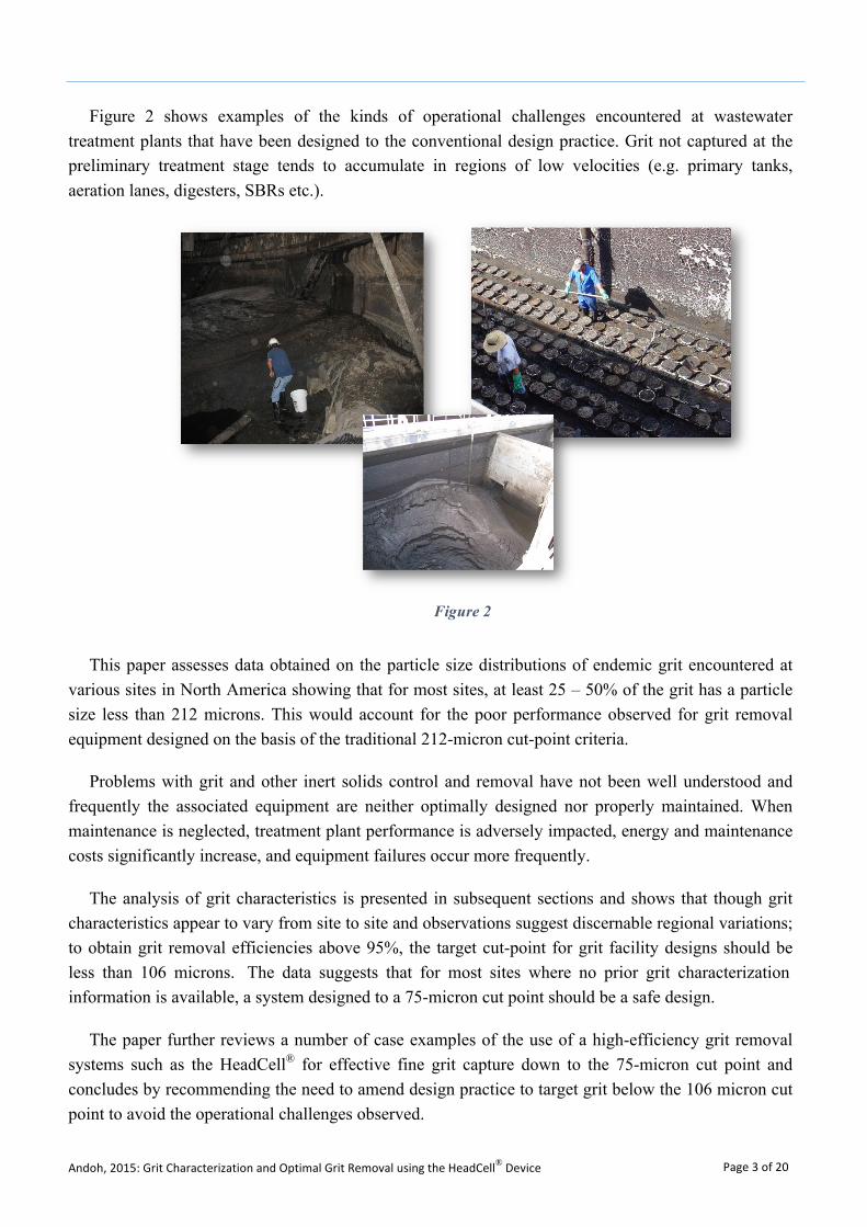
Endemic grit samples from several North American (i.e. US and Canadian) sites were analyzed for particle size distribution characterization using wet sieving techniques. A plot of the median particle size distributions for a number of the states and regions in the US and Canada is shown in Figure 3; which clearly highlights variability in the observed distributions.
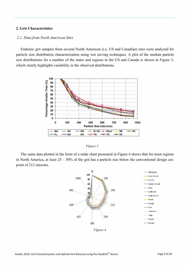
The same data plotted in the form of a radar chart presented in Figure 4 shows that for most regions in North America, at least 25 – 50% of the grit has a particle size below the conventional design cut-point of 212 microns.
Figure 3
Figure 4
Andoh, 2015: Grit Characterization and Optimal Grit Removal using the HeadCell® Device Page 5 of 20
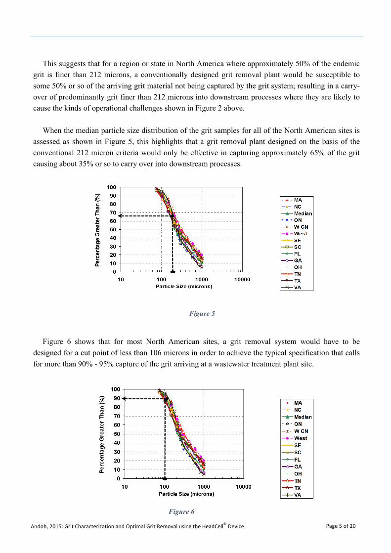
This suggests that for a region or state in North America where approximately 50% of the endemic grit is finer than 212 microns, a conventionally designed grit removal plant would be susceptible to some 50% or so of the arriving grit material not being captured by the grit system; resulting in a carry-over of predominantly grit finer than 212 microns into downstream processes where they are likely to cause the kinds of operational challenges shown in Figure 2 above.
When the median particle size distribution of the grit samples for all of the North American sites is assessed as shown in Figure 5, this highlights that a grit removal plant designed on the basis of the conventional 212 micron criteria would only be effective in capturing approximately 65% of the grit causing about 35% or so to carry over into downstream processes.
Figure 6 shows that for most North American sites, a grit removal system would have to be designed for a cut point of less than 106 microns in order to achieve the typical specification that calls for more than 90% - 95% capture of the grit arriving at a wastewater treatment plant site.
Figure 5
Figure 6
Andoh, 2015: Grit Characterization and Optimal Grit Removal using the HeadCell® Device Page 6 of 20
2.2. Observed Regional Variations and Implications for Design
The grit data was further assessed to ascertain whether there were any regional differences particularly with a focus on the portion of the particle size distributions less than 212 microns to determine whether this would also provide further insights into the observed grit characteristics and whether this could inform design choices and optimization.
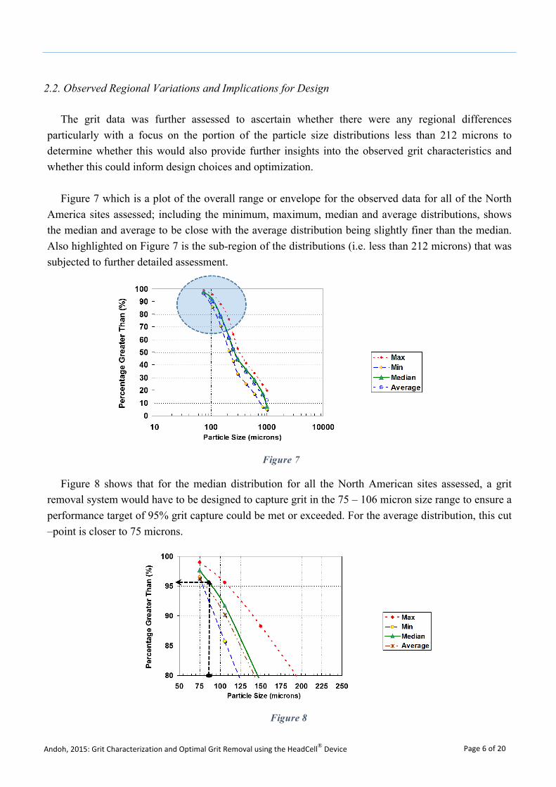
Figure 7 which is a plot of the overall range or envelope for the observed data for all of the North America sites assessed; including the minimum, maximum, median and average distributions, shows the median and average to be close with the average distribution being slightly finer than the median. Also highlighted on Figure 7 is the sub-region of the distributions (i.e. less than 212 microns) that was subjected to further detailed assessment.
Figure 8 shows that for the median distribution for all the North American sites assessed, a grit removal system would have to be designed to capture grit in the 75 – 106 micron size range to ensure a performance target of 95% grit capture could be met or exceeded. For the average distribution, this cut –point is closer to 75 microns.
Figure 7
Figure 8
Andoh, 2015: Grit Characterization and Optimal Grit Removal using the HeadCell® Device Page 7 of 20
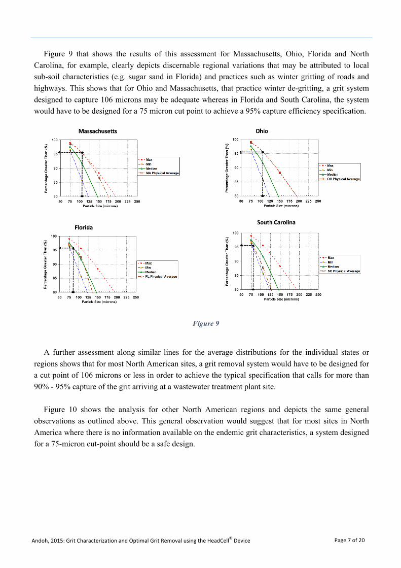
Figure 9 that shows the results of this assessment for Massachusetts, Ohio, Florida and North Carolina, for example, clearly depicts discernable regional variations that may be attributed to local sub-soil characteristics (e.g. sugar sand in Florida) and practices such as winter gritting of roads and highways. This shows that for Ohio and Massachusetts, that practice winter de-gritting, a grit system designed to capture 106 microns may be adequate whereas in Florida and South Carolina, the system would have to be designed for a 75 micron cut point to achieve a 95% capture efficiency specification.
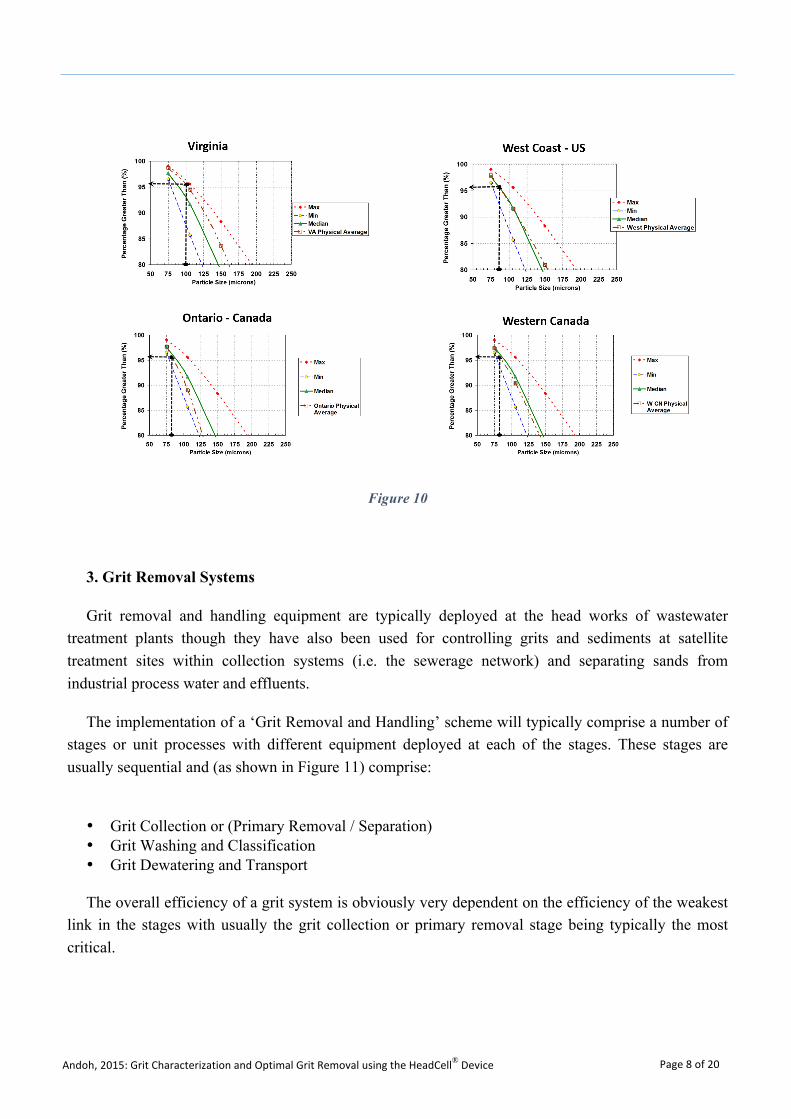
A further assessment along similar lines for the average distributions for the individual states or regions shows that for most North American sites, a grit removal system would have to be designed for a cut point of 106 microns or less in order to achieve the typical specification that calls for more than 90% - 95% capture of the grit arriving at a wastewater treatment plant site.
Figure 10 shows the analysis for other North American regions and depicts the same general observations as outlined above. This general observation would suggest that for most sites in North America where there is no information available on the endemic grit characteristics, a system designed for a 75-micron cut-point should be a safe design.
Figure 9
Andoh, 2015: Grit Characterization and Optimal Grit Removal using the HeadCell® Device Page 8 of 20
3. Grit Removal Systems
Grit removal and handling equipment are typically deployed at the head works of wastewater treatment plants though they have also been used for controlling grits and sediments at satellite treatment sites within collection systems (i.e. the sewerage network) and separating sands from industrial process water and effluents.
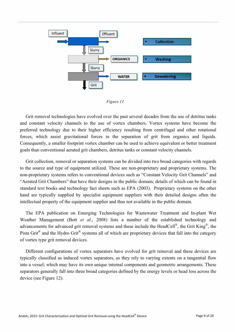
The implementation of a ‘Grit Removal and Handling’ scheme will typically comprise a number of stages or unit processes with different equipment deployed at each of the stages. These stages are usually sequential and (as shown in Figure 11) comprise:
• Grit Collection or (Primary Removal / Separation)• Grit Washing and Classification• Grit Dewatering and Transport
The overall efficiency of a grit system is obviously very dependent on the efficiency of the weakest link in the stages with usually the grit collection or primary removal stage being typically the most critical.
Figure 10
Andoh, 2015: Grit Characterization and Optimal Grit Removal using the HeadCell® Device Page 9 of 20
Grit removal technologies have evolved over the past several decades from the use of detritus tanks and constant velocity channels to the use of vortex chambers. Vortex systems have become the preferred technology due to their higher efficiency resulting from centrifugal and other rotational forces, which assist gravitational forces in the separation of grit from organics and liquids. Consequently, a smaller footprint vortex chamber can be used to achieve equivalent or better treatment goals than conventional aerated grit chambers, detritus tanks or constant velocity channels.
Grit collection, removal or separation systems can be divided into two broad categories with regards to the source and type of equipment utilized. These are non-proprietary and proprietary systems. The non-proprietary systems refers to conventional devices such as “Constant Velocity Grit Channels” and “Aerated Grit Chambers” that have their designs in the public domain; details of which can be found in standard text books and technology fact sheets such as EPA (2003). Proprietary systems on the other hand are typically supplied by specialist equipment suppliers with their detailed designs often the intellectual property of the equipment supplier and thus not available in the public domain.
The EPA publication on Emerging Technologies for Wastewater Treatment and In-plant Wet Weather Management (Bott et al., 2008) lists a number of the established technology and advancements for advanced grit removal systems and these include the HeadCell®, the Grit King®, the Pista Grit® and the Hydro Grit® systems all of which are proprietary devices that fall into the category of vortex type grit removal devices.
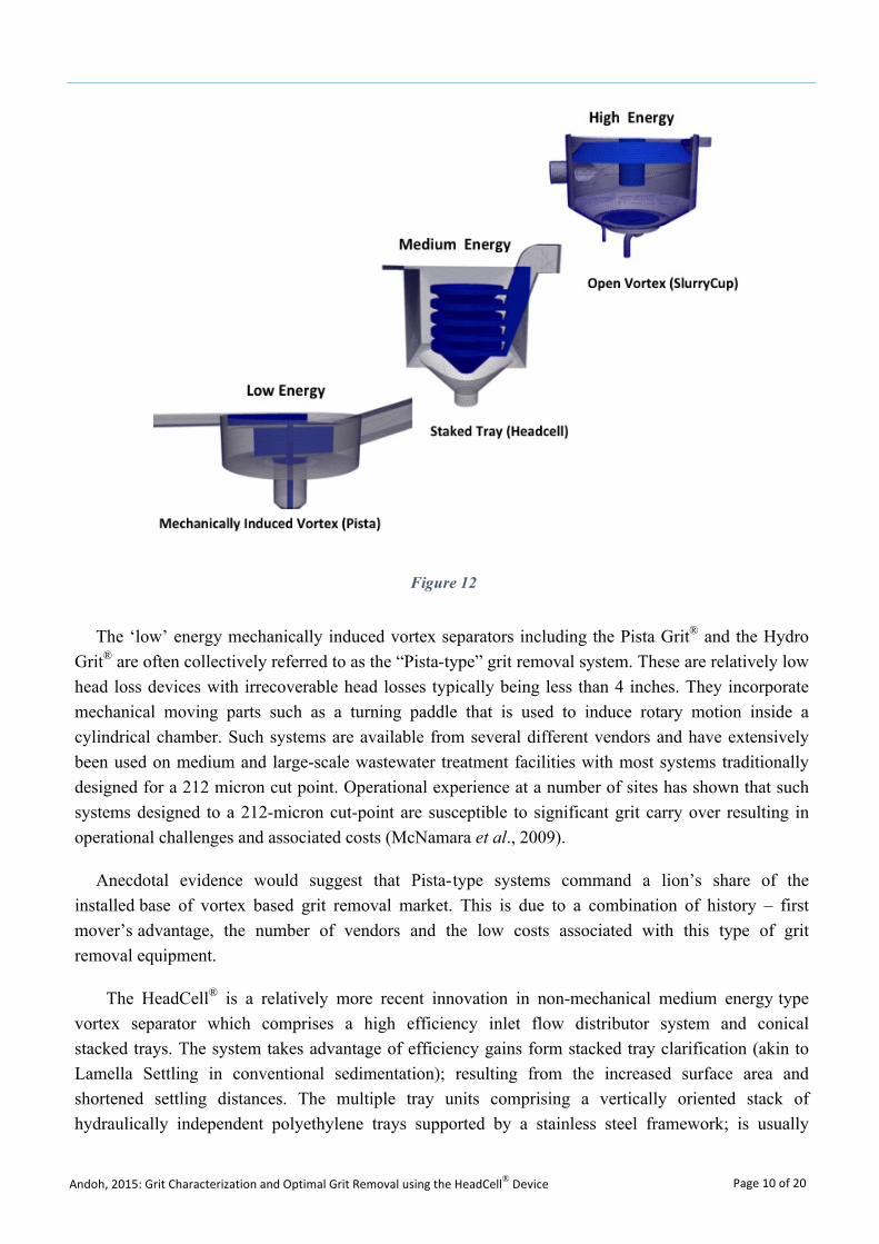
Different configurations of vortex separators have evolved for grit removal and these devices are typically classified as induced vortex separators, as they rely to varying extents on a tangential flow into a vessel; which may have its own unique internal components and geometric arrangements. These separators generally fall into three broad categories defined by the energy levels or head loss across the device (see Figure 12).
Figure 11
Andoh, 2015: Grit Characterization and Optimal Grit Removal using the HeadCell® Device Page 10 of 20
The ‘low’ energy mechanically induced vortex separators including the Pista Grit® and the Hydro Grit® are often collectively referred to as the “Pista-type” grit removal system. These are relatively low head loss devices with irrecoverable head losses typically being less than 4 inches. They incorporate mechanical moving parts such as a turning paddle that is used to induce rotary motion inside a cylindrical chamber. Such systems are available from several different vendors and have extensively been used on medium and large-scale wastewater treatment facilities with most systems traditionally designed for a 212 micron cut point. Operational experience at a number of sites has shown that such systems designed to a 212-micron cut-point are susceptible to significant grit carry over resulting in operational challenges and associated costs (McNamara et al., 2009).
Anecdotal evidence would suggest that Pista-type systems command a lion’s share of the installed base of vortex based grit removal market. This is due to a combination of history – first mover’s advantage, the number of vendors and the low costs associated with this type of grit removal equipment.
The HeadCell® is a relatively more recent innovation in non-mechanical medium energy type vortex separator which comprises a high efficiency inlet flow distributor system and conical stacked trays. The system takes advantage of efficiency gains form stacked tray clarification (akin to Lamella Settling in conventional sedimentation); resulting from the increased surface area and shortened settling distances. The multiple tray units comprising a vertically oriented stack of hydraulically independent polyethylene trays supported by a stainless steel framework; is usually
Figure 12
Andoh, 2015: Grit Characterization and Optimal Grit Removal using the HeadCell® Device Page 11 of 20
placed in a concrete basin that can be located above or at grade for new construction or in an existing basin. When retrofit into an existing basin, surface area and therefore grit removal efficiency is significantly increased at a considerably lower cost than new construction.
The uniquely designed influent distribution header feeds the inlet manifold on the HeadCell® units that evenly distributes influent tangentially into the multiple-tray system. Tangential feed establishes a vortex flow pattern where inertial forces cause the grit to travel along a circular path and settle by gravity into a boundary layer along the sloped surface of each tray. The settled solids are then conveyed by the sweeping action of the boundary layer to the center opening in each tray allowing the captured grit to settle into a single sump located below the center of the unit. De-gritted effluent flows out of the space between the trays and into the surrounding basin. The effluent typically discharges from the grit chamber over a weir, which can be located on any side of the basin, and then into an effluent trough. The ability to enter and exit from any direction minimizes footprint and maximizes the ability to retrofit into existing basins.
The HeadCell® separators have been applied to both pumped and gravity flow applications, and because they are particularly well adapted to retrofit applications, they provide a cost-effective means of uprating existing treatment plants by leveraging existing infrastructure; thereby saving significantly on project costs.
Hydrocyclones, the TeaCup™ and SlurryCup™ are examples of “high energy” vortex separators. These separators are also non-mechanical and have no moving parts. They rely on a tangential feed to generate a high energy (centrifugal forces and an open vortex regime) within a circular chamber to enhance solids liquid separation and classification. The head losses across high-energy vortex separators are significantly higher than the other two types of vortex separators, typically being in the 3–10 ft (0.9–3.1 m) range, though for some hydocyclones, head losses can exceed 20 ft (6.0 m). Because of their “high energy” requirements, these types of devices are often best suited to constant-flow pumped applications or as grit washing and classification systems.
The open vortex and boundary layer regimes established in these systems are conducive to the separators being deployed as all hydraulic no moving parts grit washing, classification and dewatering systems. Such systems have been found to be effective at retaining >95% of all grit particles 75 micron and larger.
4. Case Studies of Grit Collection
The paper further reviews a number of case examples of the use of a high-efficiency grit removal systems such as the HeadCell® for effective grit capture down to the 75-micron cut point; highlighting both the device’s efficacy, retrofit potential and footprint advantages.
Andoh, 2015: Grit Characterization and Optimal Grit Removal using the HeadCell® Device Page 12 of 20
4.1. Newberg
Newberg, a fast growing community in the Willamette Valley in Oregon needed to upgrade their wastewater treatment plant to meet projected growth within the urban growth boundary (UGB) and the urban reserve area (URA) to maintain compliance with its National Pollutant Discharge Elimination System (NPDES) permit and potential future regulations. The facility upgrade included a need for uprating the plant’s preliminary treatment comprising screening and grit removal, from an existing capacity of 18 mgd to a projected capacity of 46 mgd. The existing aerated grit system on the site was found to be undersized even for the existing flows arriving at the works; resulting in significant grit carry-over into the oxidation ditches downstream.
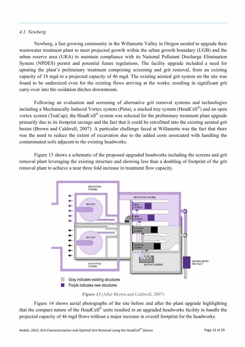
Following an evaluation and screening of alternative grit removal systems and technologies including a Mechanically Induced Vortex system (Pista), a stacked tray system (HeadCell®) and an open vortex system (TeaCup), the HeadCell® system was selected for the preliminary treatment plant upgrade primarily due to its footprint savings and the fact that it could be retrofitted into the existing aerated grit basins (Brown and Caldwell, 2007). A particular challenge faced at Willamette was the fact that there was the need to reduce the extent of excavation due to the added costs associated with handling the contaminated soils adjacent to the existing headworks.
Figure 13 shows a schematic of the proposed upgraded headworks including the screens and grit removal plant leveraging the existing structure and showing less than a doubling of footprint of the grit removal plant to achieve a near three fold increase in treatment flow capacity.
Figure 13 (After Brown and Caldwell, 2007)
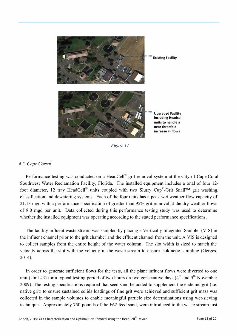
Figure 14 shows aerial photographs of the site before and after the plant upgrade highlighting that the compact nature of the HeadCell® units resulted in an upgraded headworks facility to handle the projected capacity of 46 mgd flows without a major increase in overall footprint for the headworks.
Andoh, 2015: Grit Characterization and Optimal Grit Removal using the HeadCell® Device Page 13 of 20
4.2. Cape Corral
Performance testing was conducted on a HeadCell® grit removal system at the City of Cape Coral Southwest Water Reclamation Facility, Florida. The installed equipment includes a total of four 12-foot diameter, 12 tray HeadCell® units coupled with two Slurry Cup®/Grit Snail™ grit washing, classification and dewatering systems. Each of the four units has a peak wet weather flow capacity of 21.13 mgd with a performance specification of greater than 95% grit removal at the dry weather flows of 8.0 mgd per unit. Data collected during this performance testing study was used to determine whether the installed equipment was operating according to the stated performance specifications.
The facility influent waste stream was sampled by placing a Vertically Integrated Sampler (VIS) in the influent channel prior to the grit chamber and the effluent channel from the unit. A VIS is designed to collect samples from the entire height of the water column. The slot width is sized to match the velocity across the slot with the velocity in the waste stream to ensure isokinetic sampling (Gerges, 2014).
In order to generate sufficient flows for the tests, all the plant influent flows were diverted to one unit (Unit #3) for a typical testing period of two hours on two consecutive days (4th and 5th November 2009). The testing specifications required that seed sand be added to supplement the endemic grit (i.e. native grit) to ensure sustained solids loadings of fine grit were achieved and sufficient grit mass was collected in the sample volumes to enable meaningful particle size determinations using wet-sieving techniques. Approximately 750-pounds of the F62 feed sand, were introduced to the waste stream just
Figure 14
Andoh, 2015: Grit Characterization and Optimal Grit Removal using the HeadCell® Device Page 14 of 20
prior to the HeadCell® unit. The sand was mixed with water and the sand slurry was siphoned into the waste stream at the rate of one 100-lb. bag per 20-minutes of sampling.
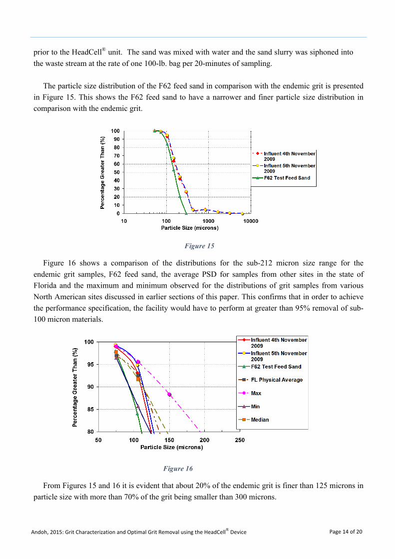
The particle size distribution of the F62 feed sand in comparison with the endemic grit is presented in Figure 15. This shows the F62 feed sand to have a narrower and finer particle size distribution in comparison with the endemic grit.
Figure 16 shows a comparison of the distributions for the sub-212 micron size range for the endemic grit samples, F62 feed sand, the average PSD for samples from other sites in the state of Florida and the maximum and minimum observed for the distributions of grit samples from various North American sites discussed in earlier sections of this paper. This confirms that in order to achieve the performance specification, the facility would have to perform at greater than 95% removal of sub-100 micron materials.
From Figures 15 and 16 it is evident that about 20% of the endemic grit is finer than 125 microns in particle size with more than 70% of the grit being smaller than 300 microns.
Figure 16
Figure 15
Andoh, 2015: Grit Characterization and Optimal Grit Removal using the HeadCell® Device Page 15 of 20
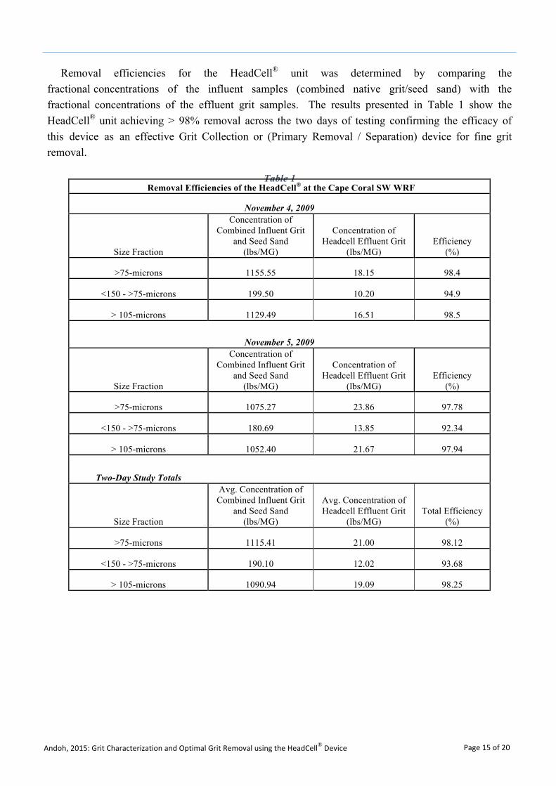
Removal efficiencies for the HeadCell® unit was determined by comparing the fractional concentrations of the influent samples (combined native grit/seed sand) with the fractional concentrations of the effluent grit samples. The results presented in Table 1 show the HeadCell® unit achieving > 98% removal across the two days of testing confirming the efficacy of this device as an effective Grit Collection or (Primary Removal / Separation) device for fine grit removal.
Table 1 Removal Efficiencies of the HeadCell® at the Cape Coral SW WRF
November 4, 2009
Size Fraction
Concentration of Combined Influent Grit
and Seed Sand (lbs/MG)
Concentration of Headcell Effluent Grit
(lbs/MG) Efficiency
(%)
>75-microns 1155.55 18.15 98.4
<150 - >75-microns 199.50 10.20 94.9
> 105-microns 1129.49 16.51 98.5
November 5, 2009
Size Fraction
Concentration of Combined Influent Grit
and Seed Sand (lbs/MG)
Concentration of Headcell Effluent Grit
(lbs/MG) Efficiency
(%)
>75-microns 1075.27 23.86 97.78
<150 - >75-microns 180.69 13.85 92.34
> 105-microns 1052.40 21.67 97.94
Two-Day Study Totals
Size Fraction
Avg. Concentration of Combined Influent Grit
and Seed Sand (lbs/MG)
Avg. Concentration of Headcell Effluent Grit
(lbs/MG) Total Efficiency
(%)
>75-microns 1115.41 21.00 98.12
<150 - >75-microns 190.10 12.02 93.68
> 105-microns 1090.94 19.09 98.25
Andoh, 2015: Grit Characterization and Optimal Grit Removal using the HeadCell® Device Page 16 of 20
5. Discussions and Conclusions
5.1. Discussions
Based on a belief that preliminary treatment processes such as screening and grit removal are a very important, but often overlooked, part of treatment facilities, the US EPA conducted a landmark study of the design and operation of these processes (EPA, 1987). The historical basis for using 0.2 mm (212 microns) as the lower size limit for grit facility design was traced back to earlier literature by Camp (1942). There has, since that time, been little or no subsequent questioning or challenging of this value. The term "grit" was found to be somewhat arbitrary and that the lower limit of grit size of concern will depend upon the nature of the collection system and the waste-water treatment processes and equipment; suggesting significant variability.
It was also found that it is difficult to interpret grit removal data because grit itself is poorly characterized and almost no data exist on relative removal efficiencies. Information on grit characteristics were found to have been derived mostly from what had been removed as grit at treatment works sites. Sieve analyses were not normally performed on grit chamber influents and effluents. For these reasons, the efficiencies of different grit removal systems could not be compared in relative terms, except in a suggested side-by-side study.
The EPA report (EPA, 1987) clearly highlighted that preliminary treatment processes can have a significant impact on the efficiency and effectiveness of downstream treatment processes, and should be designed to operate economically and reliably in the removal of grit and screenings from the wastewater flow. It noted that generally, most removed grit particles are retained on a No. 100 mesh (0.15 mm or 150 microns) sieve, reaching nearly 100 percent retention in some instances. However, grit can be much finer. In the southeast region of the US, where fine sand known as "sugar sand" constitutes a portion of the grit, less than 60 percent of one city's grit was retained on a No. 100 mesh screen; which means over 60% was finer than 150 microns in particle size; which corroborates observations from the data presented in this paper.
At the time of the EPA study (EPA, 1987), recognition of the problems associated with inadequate preliminary treatment had begun to emerge. Among the major findings was the fact that downstream and sludge system impacts related to inadequate grit and screenings removal are extensive; that accelerated equipment wear due to heavy grit loads can result in expensive and time-consuming repairs; and that jamming or clogging of process equipment by screenings can require significant manpower efforts to remedy. Of the wastewater treatment plants contacted about 60% had some downstream impacts related to grit.
Andoh, 2015: Grit Characterization and Optimal Grit Removal using the HeadCell® Device Page 17 of 20
Some specific studies including a survey of 287 municipal wastewater treatment plants revealed that preliminary treatment was rated the 15th most common design deficiency adversely affecting plant performance (Hegg, et al., 1979 and Smith et al., 1980). Similarly an Environment Canada Survey of Canadian treatment plants found that of the plants surveyed, about a third (1/3) experienced problems with grit removal (Azan and Boyko, 1973).
The information presented in this paper provides evidence to support why existing grit facilities mostly designed to the conventional 212 micron size cut-point are prone to grit carry-over into downstream processes causing resulting operational challenges and associated costs. The observed regional differences in particle size distributions presented in this paper are also in conformance with the characteristics of the “sugar sand” encountered in the Southeastern region of the US; where for States such as Florida and South Carolina, the analysis of the data presented suggests that grit facility design should be targeting 75 micron sized grit.
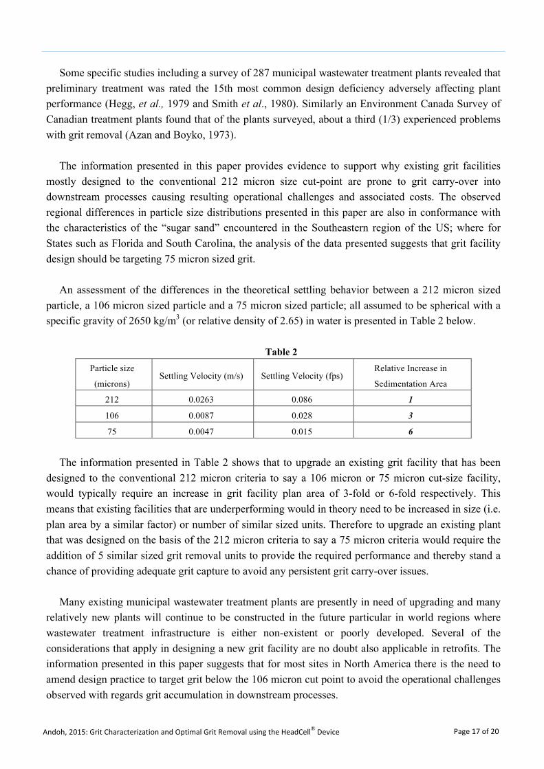
An assessment of the differences in the theoretical settling behavior between a 212 micron sized particle, a 106 micron sized particle and a 75 micron sized particle; all assumed to be spherical with a specific gravity of 2650 kg/m3 (or relative density of 2.65) in water is presented in Table 2 below.
Table 2 Particle size
(microns) Settling Velocity (m/s) Settling Velocity (fps)
Relative Increase in
Sedimentation Area
212 0.0263 0.086 1
106 0.0087 0.028 3
75 0.0047 0.015 6
The information presented in Table 2 shows that to upgrade an existing grit facility that has been designed to the conventional 212 micron criteria to say a 106 micron or 75 micron cut-size facility, would typically require an increase in grit facility plan area of 3-fold or 6-fold respectively. This means that existing facilities that are underperforming would in theory need to be increased in size (i.e. plan area by a similar factor) or number of similar sized units. Therefore to upgrade an existing plant that was designed on the basis of the 212 micron criteria to say a 75 micron criteria would require the addition of 5 similar sized grit removal units to provide the required performance and thereby stand a chance of providing adequate grit capture to avoid any persistent grit carry-over issues.
Many existing municipal wastewater treatment plants are presently in need of upgrading and many relatively new plants will continue to be constructed in the future particular in world regions where wastewater treatment infrastructure is either non-existent or poorly developed. Several of the considerations that apply in designing a new grit facility are no doubt also applicable in retrofits. The information presented in this paper suggests that for most sites in North America there is the need to amend design practice to target grit below the 106 micron cut point to avoid the operational challenges observed with regards grit accumulation in downstream processes.
Andoh, 2015: Grit Characterization and Optimal Grit Removal using the HeadCell® Device Page 18 of 20
In the US, the Clean Water State Revolving Fund (CWSRF) has been an effective tool for states and municipalities to upgrade wastewater treatment plants. In the current climate of increasing regulatory compliance requirements, with needs that exceed available funding; and the requirements for wastewater treatment plants to improve their nutrient removal capacities and the efficacy of bio-solids systems, there is a growing trend toward the use of more intensive processes. These include membrane bioreactors, micro-screens, and other high-efficiency, treatment systems and processes that require high-quality upstream preliminary treatment processes (i.e. fine grit removal and washing).
Different systems can handle different grades and characteristics of grit. Wastewater treatment plants in localities collecting a preponderance of very coarse grit can turn to the conventional grit removal technologies such as the detritus tanks, constant velocity channels and aerated grit chambers. However for the majority of plants that require high efficiency fine grit removal systems with effective grit washing and classification, municipalities should look to appropriate combinations of innovative high-efficiency grit systems; proven to capture fine grit of the order of 75 microns in size; to prevent downstream problems such as the accumulation of grit in process chambers (e.g. aeration basins and digesters).
The need to maximize their investments in treatment plant equipment is spurring municipalities and their consultants to look closer at these higher-efficiency advanced grit removal systems that can target all grades of grit. Such advanced grit removal systems that harness the inherent energy within flows to effectively capture, classify, wash and dewater fine grit, with minimal maintenance and low operational costs are becoming the technologies of choice (Bott et al., 2008). Also given that for most existing wastewater treatment sites, space may be limited, this points to the need for optimal designs that maximize the use of existing infrastructure.
The innovative HeadCell® stacked tray device provides an elegant way to upgrade underperforming grit plants by retrofitting the vertically staked trays into existing infrastructure. For example an existing underperforming plant designed for 212 micron can be upgraded to a 75 micron plant by installing a vertical stack comprising 6 trays within the same footprint as the existing plant; thus providing a cost-effective and efficient way of upgrading or uprating a grit facility whilst maximizing the utilization of existing assets and infrastructure.
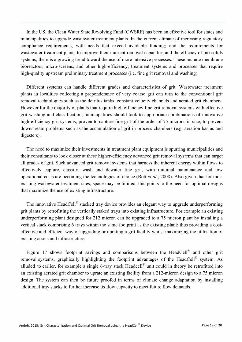
Figure 17 shows footprint savings and comparisons between the HeadCell® and other grit removal systems, graphically highlighting the footprint advantages of the HeadCell® system. As alluded to earlier, for example a single 6-tray stack Headcell® unit could in theory be retrofitted into an existing aerated grit chamber to uprate an existing facility from a 212-micron design to a 75 micron design. The system can then be future proofed in terms of climate change adaptation by installing additional tray stacks to further increase its flow capacity to meet future flow demands.
Andoh, 2015: Grit Characterization and Optimal Grit Removal using the HeadCell® Device Page 19 of 20
5.2. Conclusions
The information presented in this paper provides evidence to support why existing grit facilities, mostly designed to the conventional 212 micron size cut-point, are prone to grit carry-over into downstream processes causing resulting operational challenges and associated costs.
The analysis of endemic grit characteristics shows that though grit characteristics appear to vary from site to site, the results and observations suggest discernable regional variations and that to obtain grit removal efficiencies above 95%, the target cut-point for grit facility designs should be less than 106 microns. The data also suggests that for most sites where no prior grit characterization information is available, a system designed to a 75-micron cut point should be a safe design that ensures adequate and appropriate levels of grit capture.
The innovative HeadCell® stacked tray device provides an elegant way to upgrade underperforming grit plants or future proof existing plants (in terms of climate change adaptation) by retrofitting the vertically staked trays into existing infrastructure. For example an existing underperforming plant designed for 212 micron can be upgraded to a 75 micron plant by installing a vertical stack comprising 6 trays within the same footprint as the existing plant; thus providing a cost-effective and efficient way of upgrading or uprating a grit facility whilst maximizing the utilization of existing assets and infrastructure. The system can then be future proofed in terms of climate change adaptation by installing additional tray stacks to further increase its flow capacity to meet future flow demands.
Figure 17
Andoh, 2015: Grit Characterization and Optimal Grit Removal using the HeadCell® Device Page 20 of 20
Acknowledgements
Hydro International funded this study and the assistance of Dr. Daniel Jarman in providing inputs and Mr. Andrew Gwinn in providing data analysis assistance is gratefully acknowledged. Views expressed are solely those of the author and do not necessarily represent Hydro International.
References
1. Azan, K.M. and Boyko, B.I., 1973; Identification of Problem Areas in Water Pollution ControlPlants, Environment Canada, Research Report No. 15, 1973.
2. Bott, C., Murthy S., Pagilla, K., Richards, T., Sadick, S., Krause, T., Bishop, M., 2008; EmergingTechnologies for Wastewater Treatment and In-Plant Wet Weather Management, EPA 832-R-06-006, February 2008.
3. Brown and Caldwell, 2007; Wastewater Treatment Plant Facilities Plan Update, Prepared forthe City of Newberg, Oregon, June 26, 2007.
4. Camp, T.R., 1942; Grit Chamber Design, Sewage Works Journal, Vol. 14, March 1942.
5. EPA, 2003; Wastewater Technology Fact Sheet, Screening and Grit Removal; Office of WaterEPA 832-F-03-011, June 2003
6. EPA, 1987; Preliminary Treatment Facilities Design and Operational Considerations; UnitedState Environmental Protection Agency, Office of Municipal Pollution Control, EPA 430/19-87-007.
7. Gerges, H., 2014; Guidelines for Accurate Grit Sampling Evaluation of Sampling Techniques,Proceedings of Water Environment Federation, WEFTEC 2014, Session 400 through Session409, pp 1840- 1849 (10).
8. Hegg, B.A., Rakness, K.L., and Schultz, J.R., 1979; Evaluation of Operation and MaintenanceFactors Limiting Municipal Wastewater Treatment Plant Performance, USEPA Report No.600/2-79-034, June 1979.
9. McNamara, B. F., Griffiths, J., Book, D., 2009; True Grit. A Grit Removal EfficiencyInvestigation at Five Wastewater Treatment Plants, Proceedings of the Water EnvironmentFederation, WEFTEC 2009: Session 81 through Session 90, pp. 6160-6169(10).
10. Metcalf & Eddy, Tchobanoglous, G., Burton, F. L. 1., & Stensel, H. D., 2003; Wastewaterengineering: Treatment and reuse (4th ed.). Boston: McGraw-Hill.
11. Smith, J.M., Evans, F.L. III, and Bender, J.H., 1980; Improved Operation and MaintenanceOpportunities at Municipal Treatment Facilities, 7th US/Japan Conference on Sewage TreatmentTechnology Proceedings, USEPA Report No. 600/9-80-047, December 1980.