instrumentation - introduction principle classification of instruments
TRANSCRIPT

1
Instrumentation - Introduction
Ø Even though earliest aircraft had very few instruments such as a Compass and Air Speed Indicator, it is difficult to imagine modern aircraft without these. With enhanced aircraft capabilities, extended flying hours, difficult all weather flying conditions and passenger safety as a core issues, Pilots must be empowered with as much detail about flight as possible.
Ø At the same time, these Instruments must be friendly. Invariably Sight and Sound is used concurrently to draw Pilot’s attention. Analog and Digital readouts is also a critical issue. Digital readouts are more accurate but Analog ones are the ones which easily stand out with color bands, shaded zones etc.
Ø Ultimately the Pilot should be capable of flying only with the assistance from the Instruments and Communication with Air Traffic Controllers (ATC).
Principle Classification of Instruments
Measurements of basic quantities is possible in terms of length, weight, time, pressure and temperature. Other quantities which are essential for understanding and negotiating with any real phenomena are derived ones. For example speed = distance/time and density = mass / volume etc. Even though former formula is excellent for calibration and accurate, it is not practicable to use. Inference from Pitot tube is much more convenient for such measurement. Instruments will perform some internal manipulation to get the desired and understandable quantity. From application point of view following types of Instruments are crucial for aircraft flight.
§ Pressure type instruments § Mechanical type instruments § Gyro instruments § Electrical & Electronic instruments
2
Three Principle Categories of Instruments
o Powerplant - Information concerning operations of engine. Some of them could be Engine rpm, Temperature, Fuel and Oil Pressure Gauge etc.
o Flight & Navigational Instruments - Information concerning Flight Speed, Altitude, Attitude, Rate of Ascent or Descent, Directional Heading etc.
o System Instruments - Information concerning various systems such as Hydraulic System & its Pressure, Air conditioning, Electrical system Status etc. Safety of Aircraft & Passengers depends on accurate and reliable instruments as well as correct reading of these. At times these Instruments can forewarn the Pilot about impending disaster or calamity while in flight. Instruments and recordings could also be used for trouble shooting.
Pressure Measurements
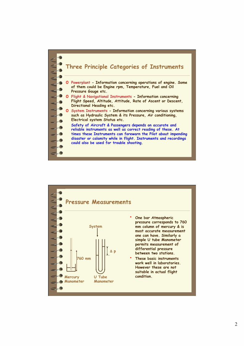
• One bar Atmospheric pressure corresponds to 760 mm column of mercury & is most accurate measurement one can have. Similarly a simple U tube Manometer permits measurement of differential pressure between two stations.
• These basic instruments work well in laboratories. However these are not suitable in actual flight condition.
System
Δ p
760 mm
Mercury Manometer
U Tube Manometer
3
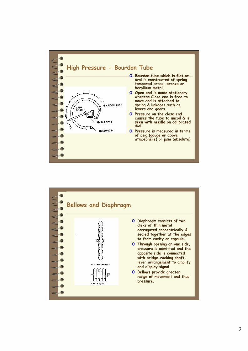
High Pressure - Bourdon Tube o Bourdon tube which is flat or
oval is constructed of spring tempered brass, bronze or beryllium metal.
o Open end is made stationary whereas Close end is free to move and is attached to spring & linkages such as levers and gears.
o Pressure on the close end causes the tube to uncoil & is seen with needle on calibrated dial.
o Pressure is measured in terms of psig (gauge or above atmosphere) or psia (absolute)
Bellows and Diaphragm
o Diaphragm consists of two disks of thin metal corrugated concentrically & sealed together at the edges to form cavity or capsule.
o Through opening on one side, pressure is admitted and the opposite side is connected with bridge-rocking shaft-lever arrangement to amplify and display signal.
o Bellows provide greater range of movement and thus pressure.
4
Pitot Tube
ρρ
ρ
ρ
Pitot Tube +
Pitot tube on the aircraft is around 25 centimeters long with a 1 centimeter diameter. Several small holes are drilled around the outside of the tube and a center hole is drilled down the axis of the tube. The outside holes are connected to one side of a device called a pressure transducer. The center hole in the tube is kept separate from the outside holes and is connected to the other side of the transducer. The transducer measures the difference in pressure in the two groups of tubes by measuring the strain in a thin element using an electronic strain gauge. The pitot tube is mounted on the aircraft so that the center tube is always pointed in the direction of travel and the outside holes are perpendicular to the center tube.
5
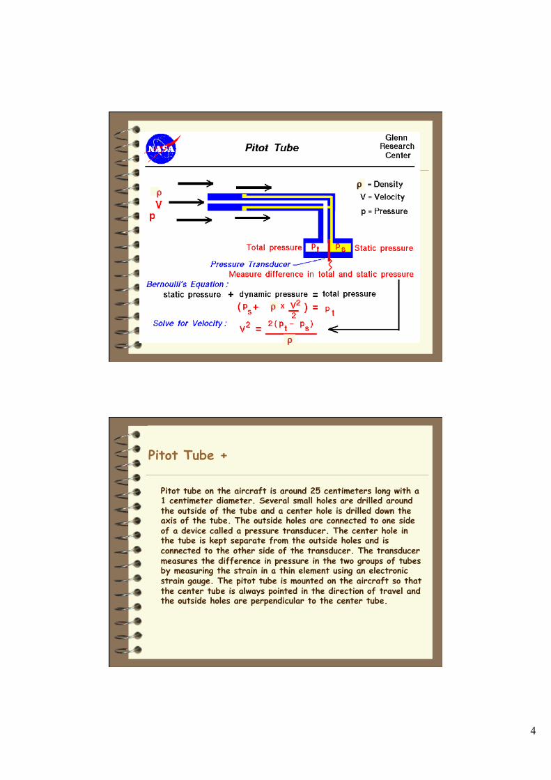
Pitot Tube + Since the outside holes are perpendicular to the direction of travel, these tubes are pressurized by the local random component of the air velocity. The pressure in these tubes is the static pressure (ps) discussed in Bernoulli's equation. The center tube, however, is pointed in the direction of travel and is pressurized by both the random and the ordered air velocity. The pressure in this tube is the total pressure (pt) discussed in Bernoulli's equation. The pressure transducer measures the difference in total and static pressure. (pt - ps). Some practical limitations:
1.If the velocity is low, the difference in pressures is very small and hard to accurately measure with the transducer. Errors in the instrument could be greater than measurement! So pitot tubes don't work very well for very low velocities.
2.If the velocity is very high (supersonic), we've violated the assumptions of Bernoulli's equation and the measurement is wrong again. At the front of the tube, a shock wave appears that will change the total pressure. There are corrections for the shock wave that can be applied to allow us to use pitot tubes for high speed aircraft.
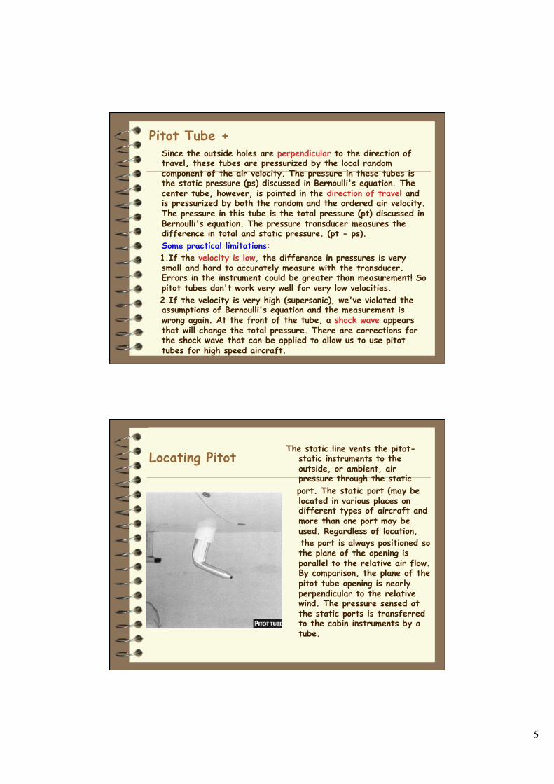
Locating Pitot The static line vents the pitot-
static instruments to the outside, or ambient, air pressure through the static
port. The static port (may be located in various places on different types of aircraft and more than one port may be used. Regardless of location,
the port is always positioned so the plane of the opening is parallel to the relative air flow. By comparison, the plane of the pitot tube opening is nearly perpendicular to the relative wind. The pressure sensed at the static ports is transferred to the cabin instruments by a tube.
6
Pitot Tube Use
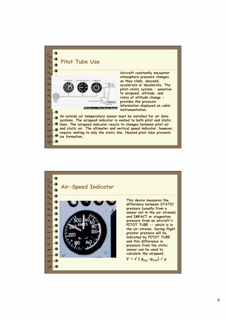
Aircraft constantly encounter atmosphere pressure changes as they climb, descend, accelerate or decelerate. The pitot-static system - sensitive to airspeed, altitude, and rates of altitude change - provides the pressure information displayed on cabin instrumentation.
An outside air temperature sensor must be installed for air data systems. The airspeed indicator is vented to both pitot and static lines. The airspeed indicator reacts to changes between pitot air and static air. The altimeter and vertical speed indicator, however, require venting to only the static line. Heated pitot tube prevents ice formation..
Air-Speed Indicator
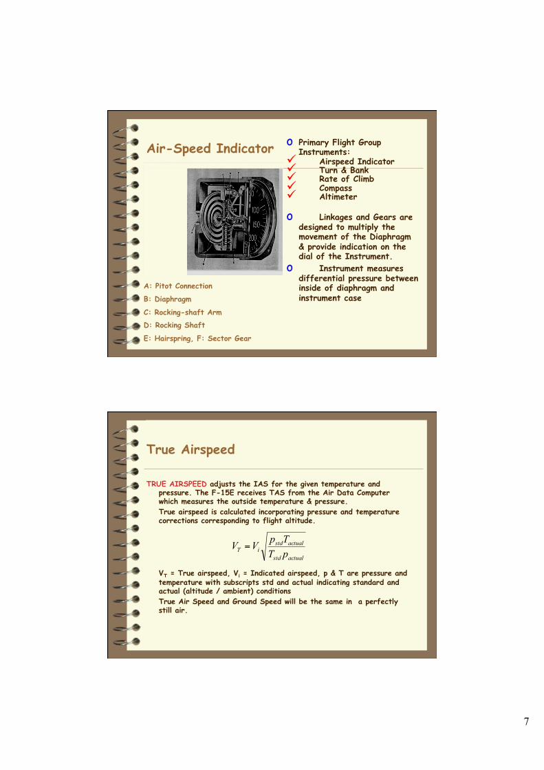
This device measures the difference between STATIC pressure (usually from a sensor not in the air-stream) and IMPACT or stagnation pressure from an aircraft's PITOT TUBE -- which is in the air-stream. During flight greater pressure will be indicated by PITOT TUBE and this difference in pressure from the static sensor can be used to calculate the airspeed. V = √ ( pstg -pstat) / ρ
7
Air-Speed Indicator o Primary Flight Group Instruments:
ü Airspeed Indicator ü Turn & Bank ü Rate of Climb ü Compass ü Altimeter
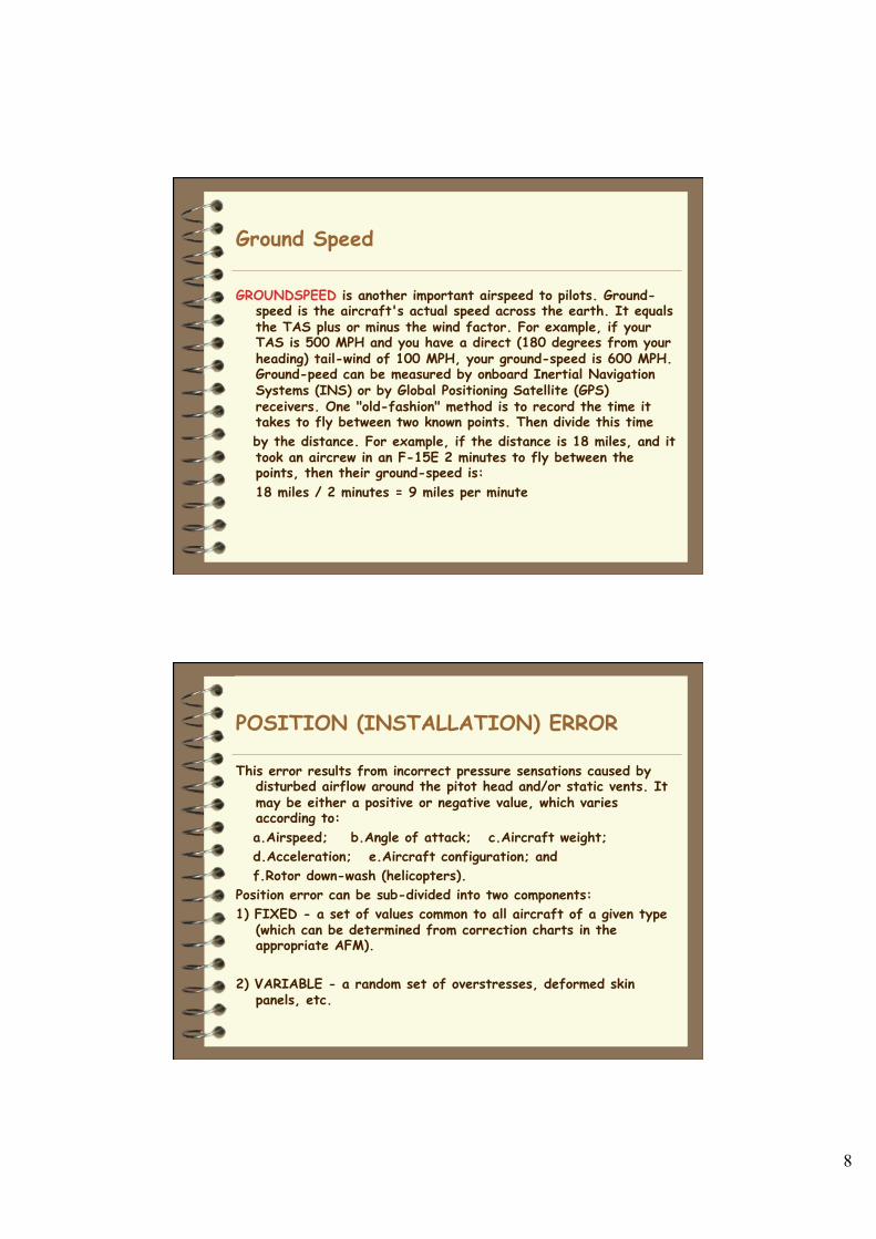
o Linkages and Gears are designed to multiply the movement of the Diaphragm & provide indication on the dial of the Instrument.
o Instrument measures differential pressure between inside of diaphragm and instrument case
A: Pitot Connection
B: Diaphragm
C: Rocking-shaft Arm D: Rocking Shaft
E: Hairspring, F: Sector Gear
True Airspeed
TRUE AIRSPEED adjusts the IAS for the given temperature and pressure. The F-15E receives TAS from the Air Data Computer which measures the outside temperature & pressure. True airspeed is calculated incorporating pressure and temperature corrections corresponding to flight altitude.
VT = True airspeed, Vi = Indicated airspeed, p & T are pressure and temperature with subscripts std and actual indicating standard and actual (altitude / ambient) conditions True Air Speed and Ground Speed will be the same in a perfectly still air.
actualstd
actualstdiT pT
TpVV =
8
Ground Speed
GROUNDSPEED is another important airspeed to pilots. Ground-speed is the aircraft's actual speed across the earth. It equals the TAS plus or minus the wind factor. For example, if your TAS is 500 MPH and you have a direct (180 degrees from your heading) tail-wind of 100 MPH, your ground-speed is 600 MPH. Ground-peed can be measured by onboard Inertial Navigation Systems (INS) or by Global Positioning Satellite (GPS) receivers. One "old-fashion" method is to record the time it takes to fly between two known points. Then divide this time
by the distance. For example, if the distance is 18 miles, and it took an aircrew in an F-15E 2 minutes to fly between the points, then their ground-speed is: 18 miles / 2 minutes = 9 miles per minute
POSITION (INSTALLATION) ERROR
This error results from incorrect pressure sensations caused by disturbed airflow around the pitot head and/or static vents. It may be either a positive or negative value, which varies according to:
a.Airspeed; b.Angle of attack; c.Aircraft weight; d.Acceleration; e.Aircraft configuration; and f.Rotor down-wash (helicopters). Position error can be sub-divided into two components: 1) FIXED - a set of values common to all aircraft of a given type
(which can be determined from correction charts in the appropriate AFM).
2) VARIABLE - a random set of overstresses, deformed skin
panels, etc.
9
Altimeter It is one of the most
important instruments especially while flying in conditions of poor visibility.
Altitude must be known for calculating other key parameters such as engine power, airspeed etc.
Altimeter works on the principle of barometer. In a sensitive altimeter there are three diaphragm capsule with two or three different dials each indicating different slab of altitude.
Altimeter should be compensated for atmosphere pressure change.
Altimeter
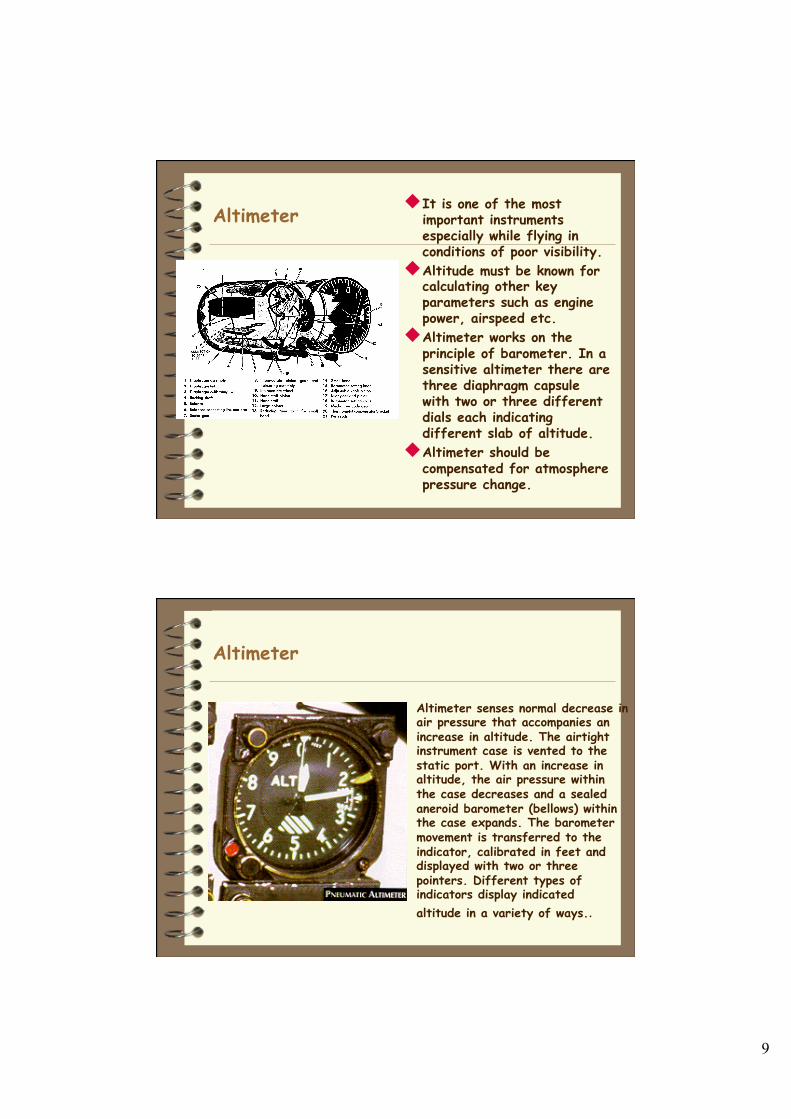
Altimeter senses normal decrease in air pressure that accompanies an increase in altitude. The airtight instrument case is vented to the static port. With an increase in altitude, the air pressure within the case decreases and a sealed aneroid barometer (bellows) within the case expands. The barometer movement is transferred to the indicator, calibrated in feet and displayed with two or three pointers. Different types of indicators display indicated altitude in a variety of ways..
10
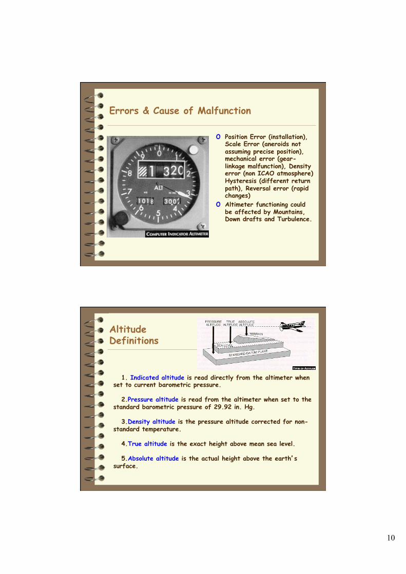
Errors & Cause of Malfunction
o Position Error (installation), Scale Error (aneroids not assuming precise position), mechanical error (gear-linkage malfunction), Density error (non ICAO atmosphere) Hysteresis (different return path), Reversal error (rapid changes)
o Altimeter functioning could be affected by Mountains, Down drafts and Turbulence.
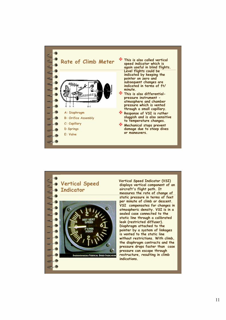
Altitude Definitions
1. Indicated altitude is read directly from the altimeter when set to current barometric pressure. 2.Pressure altitude is read from the altimeter when set to the standard barometric pressure of 29.92 in. Hg. 3.Density altitude is the pressure altitude corrected for non- standard temperature. 4.True altitude is the exact height above mean sea level. 5.Absolute altitude is the actual height above the earth’s surface.
11
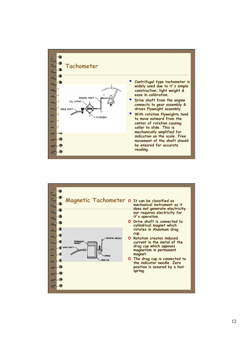
Rate of Climb Meter This is also called vertical speed indicator which is again useful in blind flights. Level flights could be indicated by keeping the pointer on zero and subsequent changes are indicated in terms of ft/minute.
This is also differential-pressure instrument -atmosphere and chamber pressure which is vented through a small capillary.
Response of VSI is rather sluggish and is also sensitive to temperature changes.
Mechanical stops prevent damage due to steep dives or maneuvers.
A: Diaphragm
B: Orifice Assembly
C: Capillary D Springs
E: Valve
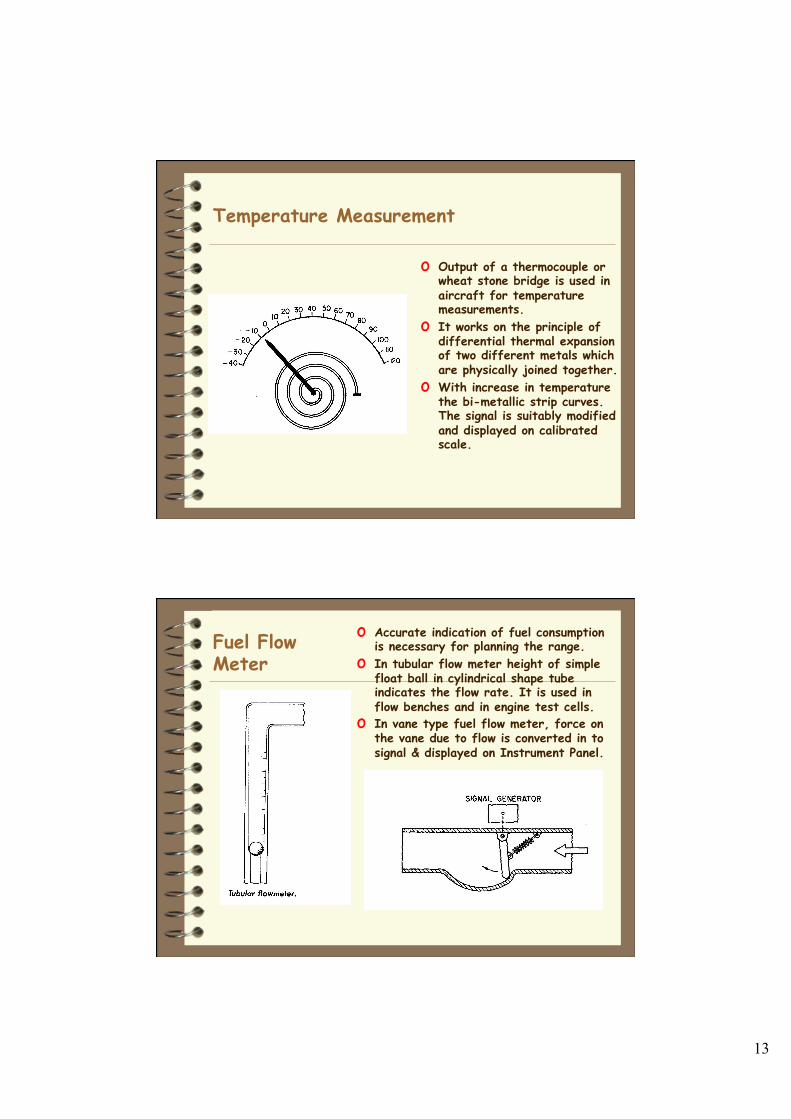
Vertical Speed Indicator
Vertical Speed Indicator (VSI) displays vertical component of an aircraft's flight path. It measures the rate of change of static pressure in terms of feet per minute of climb or descent. VSI compensates for changes in atmospheric density. VSI is in a sealed case connected to the static line through a calibrated leak (restricted diffuser). Diaphragm attached to the pointer by a system of linkages is vented to the static line without restrictions. With climb, the diaphragm contracts and the pressure drops faster than case pressure can escape through restructure, resulting in climb indications.
12
Tachometer
§ Centrifugal type tachometer is widely used due to it’s simple construction, light weight & ease in calibration.
§ Drive shaft from the engine connects to gear assembly & drives flyweight assembly.
§ With rotation flyweights tend to move outward from the center of rotation causing collar to slide. This is mechanically amplified for indication on the scale. Free movement of the shaft should be ensured for accurate reading.
Magnetic Tachometer o It can be classified as mechanical instrument as it does not generate electricity nor requires electricity for it’s operation.
o Drive shaft is connected to cylindrical magnet which rotates in Aluminum drag cup.
o Rotation creates induced current in the metal of the drag cup which opposes magnetism in permanent magnet.
o The drag cup is connected to the indicator needle. Zero position is assured by a hair spring.
13
Temperature Measurement
o Output of a thermocouple or wheat stone bridge is used in aircraft for temperature measurements.
o It works on the principle of differential thermal expansion of two different metals which are physically joined together.
o With increase in temperature the bi-metallic strip curves. The signal is suitably modified and displayed on calibrated scale.
Fuel Flow Meter
o Accurate indication of fuel consumption is necessary for planning the range.
o In tubular flow meter height of simple float ball in cylindrical shape tube indicates the flow rate. It is used in flow benches and in engine test cells.
o In vane type fuel flow meter, force on the vane due to flow is converted in to signal & displayed on Instrument Panel.
14
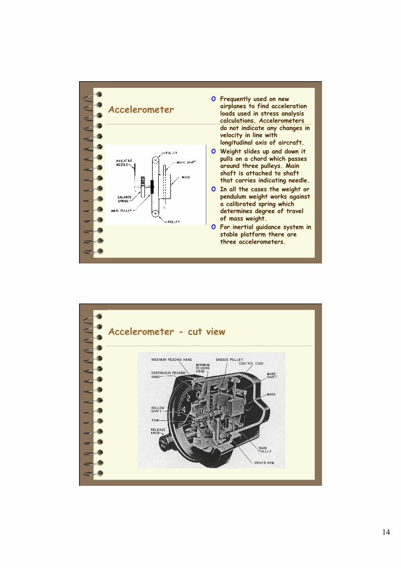
Accelerometer o Frequently used on new
airplanes to find acceleration loads used in stress analysis calculations. Accelerometers do not indicate any changes in velocity in line with longitudinal axis of aircraft.
o Weight slides up and down it pulls on a chord which passes around three pulleys. Main shaft is attached to shaft that carries indicating needle.
o In all the cases the weight or pendulum weight works against a calibrated spring which determines degree of travel of mass weight.
o For inertial guidance system in stable platform there are three accelerometers.
Accelerometer - cut view
15
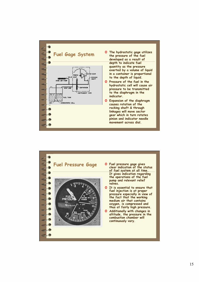
Fuel Gage System o The hydrostatic gage utilizes the pressure of the fuel developed as a result of depth to indicate fuel quantity as the pressure exerted by a volume of liquid in a container is proportional to the depth of liquid.
o Pressure of the fuel in the hydrostatic cell will cause air pressure to be transmitted to the diaphragm in the indicator.
o Expansion of the diaphragm causes rotation of the rocking shaft & through linkages will move sector gear which in turn rotates pinion and indicator needle movement across dial.
Fuel Pressure Gage o Fuel pressure gage gives clear indication of the status of fuel system at all time. It gives indication regarding the operations of the fuel pump and relevant relief valves.
o It is essential to ensure that fuel injection is at proper pressure especially in view of the fact that the working medium air that contains oxygen, is compressed and thus at fairly high pressure.
o Additionally with changes in altitude, the pressure in the combustion chamber will continuously vary.