numerical simulation of nondestructive testing, an ... · numerical simulation of nondestructive...
TRANSCRIPT
Numerical simulation of nondestructive testing, an advanced tool for safety analysis
Gérard Cattiaux, Thierry Sollier
Institut de Radioprotection et de Sûreté Nucléaire (IRSN) Reactor Safety Division
BP 17 – 92262 Fontenay-aux-Roses cedex, France
Abstract: For safety analysis purposes, the IRSN needs to assess the performance and limitations of nondestructive test (NDT) methods being used in the nuclear industry. Numerical simulation is one of the tools that is suited to such assessments. This approach can improve understanding and facilitate analysis of the physical mechanisms involved in several types of NDT (ultrasonic, radiographic and eddy current techniques). For many years, the IRSN has participated in developing the numerical simulation functions required for its own safety analyses. These functions have been integrated into the CIVA NDT platform developed by the CEA and are now accessible to all other users, in particular nuclear facility operators. This paper presents various applications for numerical simulation in IRSN safety analyses and describes R&D currently being conducted on enhanced modelling of the relevant NDT methods.
1 QUALIFICATION OF NDT METHODS USED FOR IN-SERVICE INSPECTION OF NUCLEAR EQUIPMENT
NDT methods used for in-service monitoring of nuclear facilities or equipment (reactor pressure vessel, experimental and naval propulsion reactors, packaging for transport of radioactive materials, etc.) must be qualified or assessed to determine, with a high degree of confidence, their flaw detection and characterisation capabilities. For nuclear power plants, NDT practices are codified in the Rules for In-Service Inspection of Mechanical Components (RSE-M) and are qualified in accordance with article 8 of the French government ruling of November 10, 1999 on surveillance of the reactor coolant pressure and secondary system pressure boundaries. The process applicable to pressurised water reactors (PWRs) is described in [1]. It is the IRSN's view that for other facilities or equipment for which practical requirements are either in the process of being formalised or have yet to be so, performance should be assessable under conditions similar to those considered for nuclear power plants.
NDT qualification is thus intended to demonstrate that a test method used for a given zone of equipment adequately detects and characterises any degradation likely to affect that equipment.
2 MEANS FOR ASSESSING THE PERFORMANCE OF NDT METHODS
NDT flaw detection and sizing performance must be sufficient to determine, with a high degree of confidence, any need for repair or special surveillance of the affected component. Such performance is often deduced from experiments performed on representative
2
mock-ups of tested components that contain artificial or realistic defects with characteristics1 resembling those of the flaws potentially induced by in-service damage mechanisms. Mock-ups, however, tend to be costly and are often specific to the component and zone (in particular welded zone) of interest. In most mock-ups, flaws cannot be reasonably replicated for more than a limited number of cases, which leads to inadequate assessment of NDT performance.
Numerical simulation offers a means for enhancing current knowledge of NDT performance, as ENIQ2 advocated at the end of its work on NDT qualification in the mid-1990s. Such simulation can be included in the qualification process to supplement mock-up experiments, for clearly identified flaws related to postulated or observed degradation mechanisms.
In some cases, however, there is no operational experience available for identifying particular degradation mechanisms and predicting related flaws. Where this is true, simulation can confirm the fitness of the NDT method for detecting hypothetical flaws. It likewise reinforces qualification of NDT methods under a defence-in-depth strategy considered vital by the IRSN for components subject to the break preclusion concept.
The following paragraphs describe the IRSN's contribution to the development of NDT simulation software and its application of this tool to safety analysis, with the help of a few examples.
3 USE OF NDT SIMULATION FOR IRSN ASSESSMENT PURPOSES
As a technical support entity for the French nuclear safety authorities3, the IRSN is regularly asked to assess NDT methods currently in use and, where necessary, to report on their real performance. After completion of work on this subject by ENIQ and NRWG4and the advent of regulations for qualification of NDT methods used in PWRs, the IRSN decided to avail itself of the best existing NDT simulation methods for its own assessments. It thus became closely involved in defining simulation requirements that would cover as broad as possible a range of nuclear facilities and equipment. This meant use of simulation tools that could verify the flaw detection and sizing performance of the most common nuclear industry NDT methods, independently of any utility, manufacturer or service provider. Initially developed to simulate ultrasonic testing, such software now permits simulation of gamma and X-ray inspections, as well as eddy current techniques. The many developments included in the CIVA platform are now available to a large community of users.
In every case, rigorous experimental validation is required for the three main types of NDT – ultrasonic, eddy current and radiographic testing [2][3][4][5][6][7]. For radiographic testing, joint studies recently begun by the IRSN and CEA/LIST have already enabled more realistic simulation of complex parts, materials and flaws. Such simulations in turn permit impact studies based on variation of numerous parameters. What now remains is to compare predictions of various flaws detected by simulation (including those at the edge of the visibility range) with results read from actual radiographic films. Future work will thus include experiments intended to validate models and to reinforce their flaw prediction capability, using parts of components illustrative of those present in nuclear facilities.
1 i.e. orientation, dimensions, type (volumetric or planar), opening, facies, etc. 2 ENIQ: European Network for Inspection Qualification, a working group made up of representatives from all the European utilities. 3 which include ASN (French Nuclear Safety Authority for civil facilities and activities) and ASND (French Nuclear Safety Authority for defense-related facilities and activities) 4 NRWG: Nuclear Regulatory Working Group, made up of representatives from the European safety authorities.
3
Areas of development for the three NDT methods are as follows:
- for ultrasonic testing: simulation of complex weld tests using flat, contact-type transducers, and reactor vessel tests using focused immersion transducers; performance of simulations on electrical discharge-machined planar flaws and flaws with complex shapes (e.g. cracks); making allowance for flaw misorientation effects; and simulation of tests most commonly applied to dissimilar metal welds (including validation against experimental data). A joint IRSN/NRC research project is currently focusing on coarse-grained heterogeneous materials.
- for eddy current testing: simulation of tests performed on straight sections of PWR steam generator tubes, in the vicinities of tube support plates, with various deposit build-ups, for flaws of both simple and complex shape; simulation of matrix-type transducers, etc.
- for radiographic testing: simulation of test cases most commonly encountered in nuclear facilities (nozzles, dissimilar metal welds, complex-shaped components and flaws, etc.).
In all these cases, CAD software is readily available to describe the most complex components and flaws.
Both the nuclear industry (in particular EDF) and the aerospace industry are contributing to the enhancement and extension of numerical simulation models, thereby supplementing studies undertaken by the IRSN. The radiographic test module implemented in CIVA simulates gamma and X-ray inspections by integrating the Moderato and Sindbad codes developed by EDF and CEA/LETI respectively. CIVA likewise proposes response models for film used in industrial radiography. The next paragraphs present several examples of simulations for nondestructive ultrasonic, radiographic and eddy current testing.
3.1 Simulation of ultrasonic testing with a focused immersion transducer
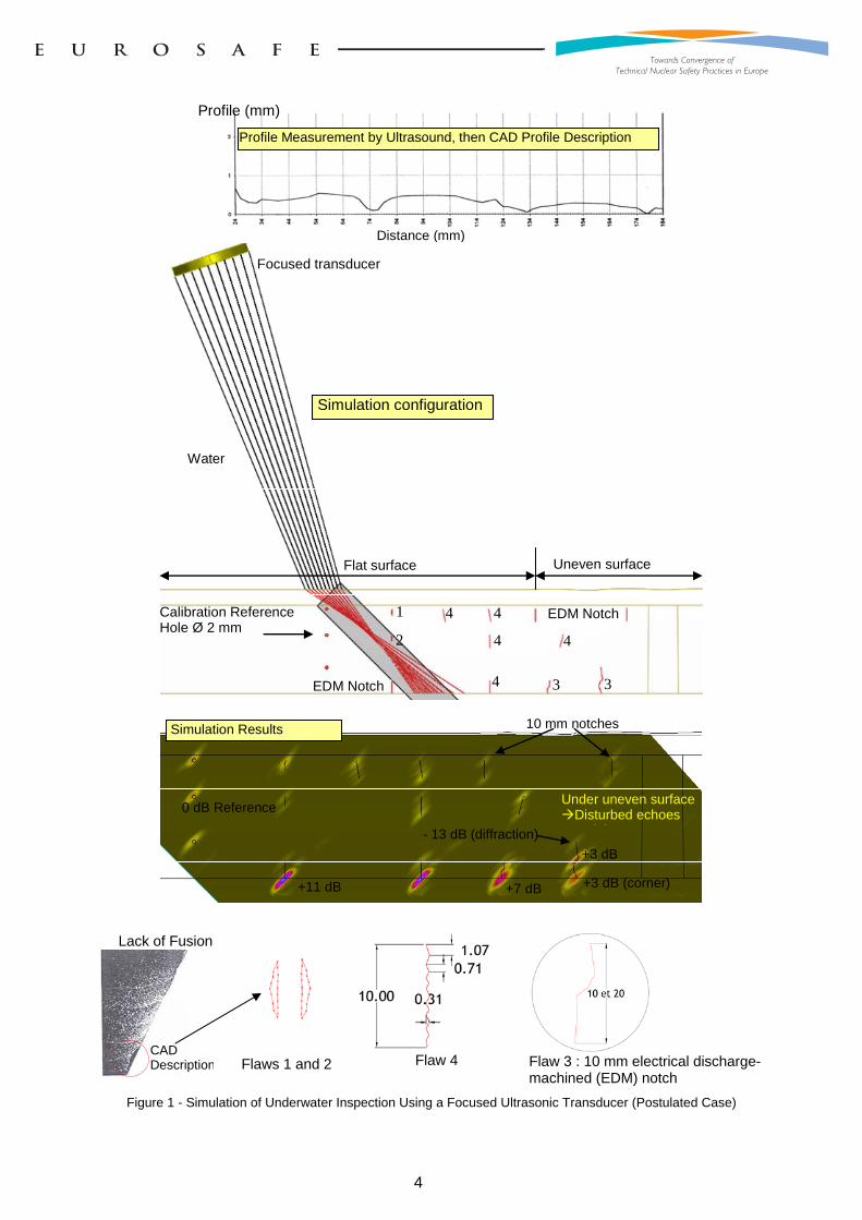
This simulation shows (Figure 1) ultrasonic tests conducted using a focused immersion transducer. The part tested is fictitious, for better illustration of the simulated functions, but nevertheless reflects a type of simulation appropriate for evaluating reactor vessel weld inspections.
This simulation serves to estimate the detectability of various crack-type flaws with simple or complex geometries, in the parts tested. It enables display of various acoustic phenomena generated by complex flaws (e.g. diffraction signals from crack tops or roots, which are used to size planar flaws). The simulated part likewise includes both flat and geometrically complex surfaces, thus enabling assessment of impact due to uneven surface state5 on flaw detectability and sizing. Ultrasonic signal amplitudes are expressed in decibels. In the example shown in Figure 1, amplitude values obtained for the different flaws are based on the value measured for a reference reflector6 .
5 This consists of a layer of partially grinded stainless steel cladding deposited on a ferritic steel base. 6 Reference amplitude measured for a cylindrical hole = 0 dB.
4
Distance (mm)
Profile (mm)
Profile Measurement by Ultrasound, then CAD Profile Description
Flat surface Uneven surface
1
2
3 3 EDM Notch
4 4
4
4
4
EDM Notch Calibration Reference Hole Ø 2 mm
Focused transducer
Water
Simulation configuration
0 dB Reference
+11 dB +7 dB +3 dB (corner)
+3 dB
- 13 dB (diffraction)
10 mm notches
Under uneven surface Disturbed echoes
bé
Simulation Results
Lack of Fusion
CAD Description
Flaws 1 and 2
Flaw 4
Flaw 3 : 10 mm electrical discharge-machined (EDM) notch
Figure 1 - Simulation of Underwater Inspection Using a Focused Ultrasonic Transducer (Postulated Case)
5
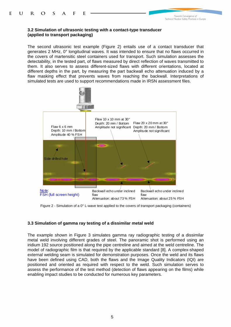
3.2 Simulation of ultrasonic testing with a contact-type transducer (applied to transport packaging)
The second ultrasonic test example (Figure 2) entails use of a contact transducer that generates 2 MHz, 0° longitudinal waves. It was intended to ensure that no flaws occurred in the covers of martensitic steel containers used for transport. Such simulation assesses the detectability, in the tested part, of flaws measured by direct reflection of waves transmitted to them. It also serves to assess different-sized flaws with different orientations, located at different depths in the part, by measuring the part backwall echo attenuation induced by a flaw masking effect that prevents waves from reaching the backwall. Interpretations of simulated tests are used to support recommendations made in IRSN assessment files.
Flaw 6 x 6 mm
Depth: 10 mm / Bottom Amplitude 40 % FSH
Flaw 10 x 10 mm at 30°Depth: 20 mm / Bottom Amplitude not signif icant
Backwall echo under inclined flaw Attenuation: about 73 % FSH
Backwall echo under inclined flaw At tenuation: about 25 % FSH
Flaw 20 x 20 mm at 30° Depth: 20 mm / Bottom Amplitude not significant
Side drilled hole
Note: FSH (full screen height)
Figure 2 - Simulation of a 0° L-wave test applied to the covers of transport packaging (containers)
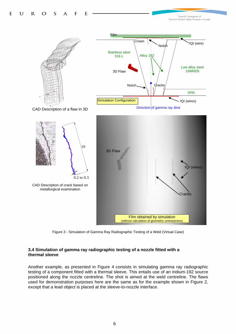
3.3 Simulation of gamma ray testing of a dissimilar metal weld
The example shown in Figure 3 simulates gamma ray radiographic testing of a dissimilar metal weld involving different grades of steel. The panoramic shot is performed using an iridium 192 source positioned along the pipe centreline and aimed at the weld centreline. The model of radiographic film is that required by the applicable standard [8]. A complex-shaped external welding seam is simulated for demonstration purposes. Once the weld and its flaws have been defined using CAD, both the flaws and the Image Quality Indicators (IQI) are positioned and oriented as required with respect to the weld. Such simulation serves to assess the performance of the test method (detection of flaws appearing on the films) while enabling impact studies to be conducted for numerous key parameters.
6
CAD Description of a flaw in 3D
3D Flaw
IQI (wire)
Cracks
Simulation Configuration IQI (wires)
Notch
Stainless steel316 L
Low alloy steel16MND5
Alloy 182
Film
309L
Crown
Notch
Direction of gamma ray shot
IQI (wires)
3D Flaw
Cracks
Film obtained by simulation (without calculation of geometric unsharpness)
10
0.2 to 0.3
CAD Description of crack based on metallurgical examination
Figure 3 - Simulation of Gamma Ray Radiographic Testing of a Weld (Virtual Case)
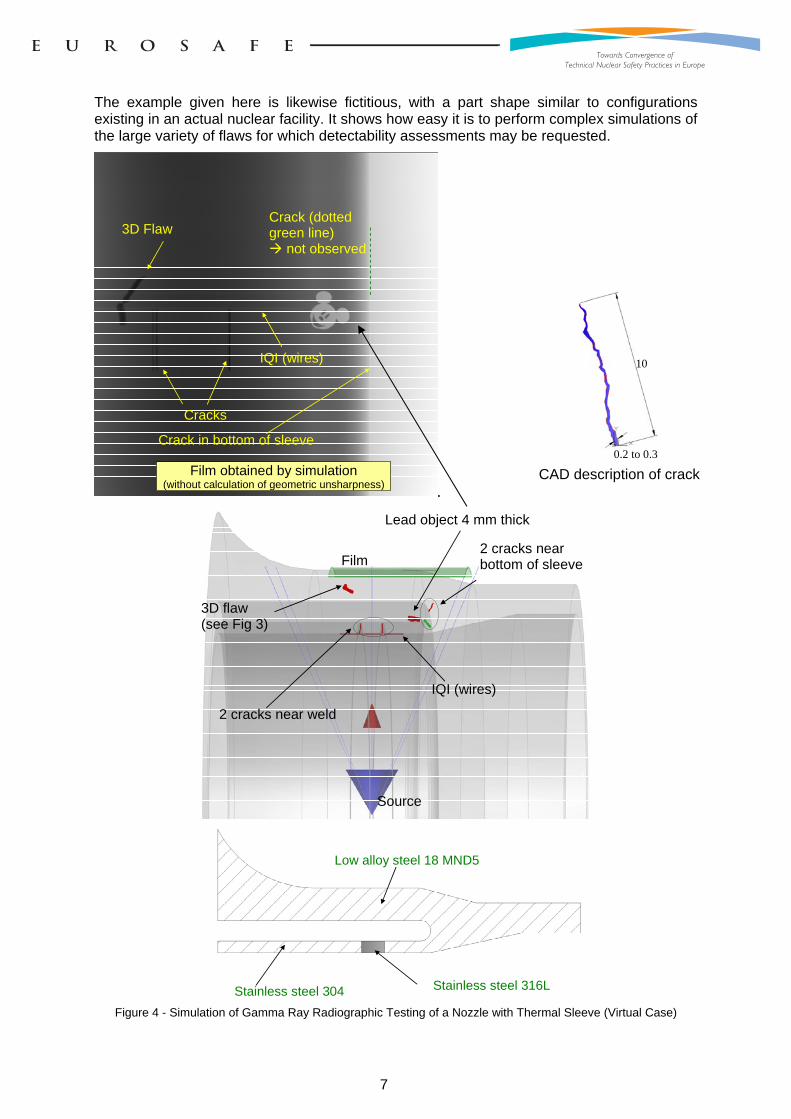
3.4 Simulation of gamma ray radiographic testing of a nozzle fitted with a thermal sleeve
Another example, as presented in Figure 4 consists in simulating gamma ray radiographic testing of a component fitted with a thermal sleeve. This entails use of an iridium-192 source positioned along the nozzle centreline. The shot is aimed at the weld centreline. The flaws used for demonstration purposes here are the same as for the example shown in Figure 2, except that a lead object is placed at the sleeve-to-nozzle interface.
7
The example given here is likewise fictitious, with a part shape similar to configurations existing in an actual nuclear facility. It shows how easy it is to perform complex simulations of the large variety of flaws for which detectability assessments may be requested.
IQI (wires)
3D Flaw
Film obtained by simulation (without calculation of geometric unsharpness)
Cracks
Crack in bottom of sleeve
Crack (dotted green line) not observed
10
0.2 to 0.3 CAD description of crack
IQI (wires)
Film
Source
2 cracks near weld
3D flaw (see Fig 3)
2 cracks near bottom of sleeve
Lead object 4 mm thick
Stainless steel 304
Low alloy steel 18 MND5
Stainless steel 316L
Figure 4 - Simulation of Gamma Ray Radiographic Testing of a Nozzle with Thermal Sleeve (Virtual Case)
8
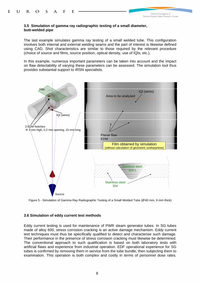
3.5 Simulation of gamma ray radiographic testing of a small diameter, butt-welded pipe
The last example simulates gamma ray testing of a small welded tube. This configuration involves both internal and external welding seams and the part of interest is likewise defined using CAD. Shot characteristics are similar to those required by the relevant procedure (choice of source and films, source position, optical density, use of IQIs, etc.).
In this example, numerous important parameters can be taken into account and the impact on flaw detectability of varying these parameters can be assessed. The simulation tool thus provides substantial support to IRSN specialists.
3 EDM Notches 3 mm high, 0.2 mm opening, 15 mm long
IQI (wires)
Film
Source
IQI (wires)
Planar flaw EDM
Film obtained by simulation (without calculation of geometric unsharpness)
Area to be analysed
Stainless steel 316 L
Stainless steel 304
Figure 5 - Simulation of Gamma Ray Radiographic Testing of a Small Welded Tube (Ø 60 mm, 9 mm thick)
3.6 Simulation of eddy current test methods
Eddy current testing is used for maintenance of PWR steam generator tubes. In SG tubes made of alloy 600, stress corrosion cracking is an active damage mechanism. Eddy current test techniques must thus be specifically qualified to detect and characterise such damage. Their performance in the presence of stress corrosion cracking must likewise be determined. The conventional approach to such qualification is based on both laboratory tests with artificial flaws and experience from industrial operation. EDF operational experience for SG tubes is confirmed by removing them in service from the tube bundle, then subjecting them to examination. This operation is both complex and costly in terms of personnel dose rates.
9
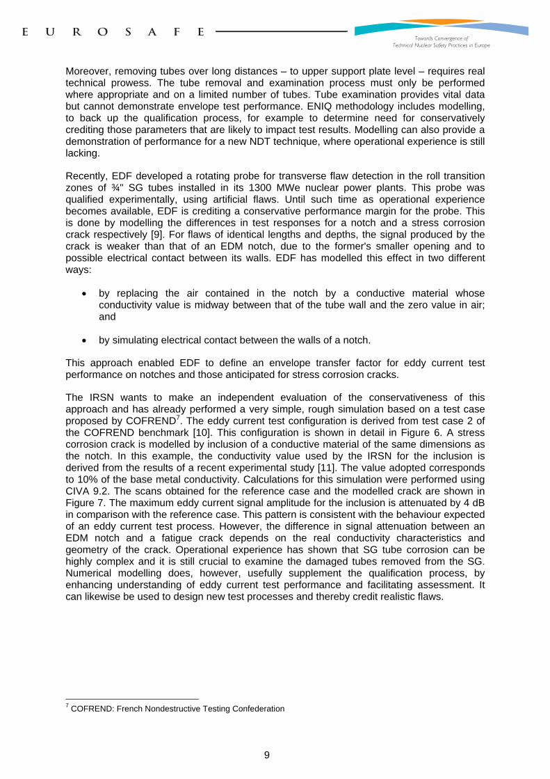
Moreover, removing tubes over long distances – to upper support plate level – requires real technical prowess. The tube removal and examination process must only be performed where appropriate and on a limited number of tubes. Tube examination provides vital data but cannot demonstrate envelope test performance. ENIQ methodology includes modelling, to back up the qualification process, for example to determine need for conservatively crediting those parameters that are likely to impact test results. Modelling can also provide a demonstration of performance for a new NDT technique, where operational experience is still lacking.
Recently, EDF developed a rotating probe for transverse flaw detection in the roll transition zones of ¾" SG tubes installed in its 1300 MWe nuclear power plants. This probe was qualified experimentally, using artificial flaws. Until such time as operational experience becomes available, EDF is crediting a conservative performance margin for the probe. This is done by modelling the differences in test responses for a notch and a stress corrosion crack respectively [9]. For flaws of identical lengths and depths, the signal produced by the crack is weaker than that of an EDM notch, due to the former's smaller opening and to possible electrical contact between its walls. EDF has modelled this effect in two different ways:
by replacing the air contained in the notch by a conductive material whose conductivity value is midway between that of the tube wall and the zero value in air; and
by simulating electrical contact between the walls of a notch.
This approach enabled EDF to define an envelope transfer factor for eddy current test performance on notches and those anticipated for stress corrosion cracks.
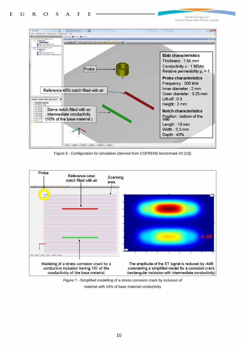
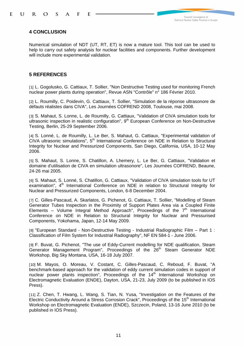
The IRSN wants to make an independent evaluation of the conservativeness of this approach and has already performed a very simple, rough simulation based on a test case proposed by COFREND7. The eddy current test configuration is derived from test case 2 of the COFREND benchmark [10]. This configuration is shown in detail in Figure 6. A stress corrosion crack is modelled by inclusion of a conductive material of the same dimensions as the notch. In this example, the conductivity value used by the IRSN for the inclusion is derived from the results of a recent experimental study [11]. The value adopted corresponds to 10% of the base metal conductivity. Calculations for this simulation were performed using CIVA 9.2. The scans obtained for the reference case and the modelled crack are shown in Figure 7. The maximum eddy current signal amplitude for the inclusion is attenuated by 4 dB in comparison with the reference case. This pattern is consistent with the behaviour expected of an eddy current test process. However, the difference in signal attenuation between an EDM notch and a fatigue crack depends on the real conductivity characteristics and geometry of the crack. Operational experience has shown that SG tube corrosion can be highly complex and it is still crucial to examine the damaged tubes removed from the SG. Numerical modelling does, however, usefully supplement the qualification process, by enhancing understanding of eddy current test performance and facilitating assessment. It can likewise be used to design new test processes and thereby credit realistic flaws.
7 COFREND: French Nondestructive Testing Confederation
10
Figure 6 - Configuration for simulation (derived from COFREND benchmark #2 [10])
Figure 7 - Simplified modelling of a stress corrosion crack by inclusion of
material with 10% of base material conductivity
11
4 CONCLUSION
Numerical simulation of NDT (UT, RT, ET) is now a mature tool. This tool can be used to help to carry out safety analysis for nuclear facilities and components. Further development will include more experimental validation.
5 REFERENCES
[1] L. Gogolusko, G. Cattiaux, T. Sollier, "Non Destructive Testing used for monitoring French nuclear power plants during operation", Revue ASN "Contrôle" n° 186 Février 2010.
[2] L. Roumilly, C. Poidevin, G. Cattiaux, T. Sollier, "Simulation de la réponse ultrasonore de défauts réalistes dans CIVA", Les Journées COFREND 2008, Toulouse, mai 2008.
[3] S. Mahaut, S. Lonne, L. de Roumilly, G. Cattiaux, "Validation of CIVA simulation tools for ultrasonic inspection in realistic configuration", 9th European Conference on Non-Destructive Testing, Berlin, 25-29 September 2006.
[4] S. Lonné, L. de Roumilly, L. Le Ber, S. Mahaut, G. Cattiaux, "Experimental validation of CIVA ultrasonic simulations", 5th International Conference on NDE in Relation to Structural Integrity for Nuclear and Pressurized Components, San Diego, California, USA, 10-12 May 2006.
[5] S. Mahaut, S. Lonne, S. Chatillon, A. Lhemery, L. Le Ber, G. Cattiaux, "Validation et domaine d'utilisation de CIVA en simulation ultrasonore", Les Journées COFREND, Beaune, 24-26 mai 2005.
[6] S. Mahaut, S. Lonné, S. Chatillon, G. Cattiaux, "Validation of CIVA simulation tools for UT examination", 4th International Conference on NDE in relation to Structural Integrity for Nuclear and Pressurized Components, London, 6-8 December 2004.
[7] C. Gilles-Pascaud, A. Skarlatos, G. Pichenot, G. Cattiaux, T. Sollier, "Modelling of Steam Generator Tubes Inspection in the Proximity of Support Plates Area via a Coupled Finite Elements – Volume Integral Method Approach", Proceedings of the 7th International Conference on NDE in Relation to Structural Integrity for Nuclear and Pressurised Components, Yokohama, Japan, 12-14 May 2009.
[8] "European Standard - Non-Destructive Testing - Industrial Radiographic Film – Part 1 : Classification of Film System for Industrial Radiography", NF EN 584-1 - June 2006.
[9] F. Buvat, G. Pichenot, "The use of Eddy-Current modelling for NDE qualification, Steam Generator Management Program", Proceedings of the 26th Steam Generator NDE Workshop, Big Sky Montana, USA, 16-18 July 2007.
[10] M. Mayos, O. Moreau, V. Costant, C. Gilles-Pascaud, C. Reboud, F. Buvat, "A benchmark-based approach for the validation of eddy current simulation codes in support of nuclear power plants inspection", Proceedings of the 14th International Workshop on Electromagnetic Evaluation (ENDE), Dayton, USA, 21-23, July 2009 (to be published in IOS Press).
[11] Z. Chen, T. Hwang, L. Wang, S. Tian, N. Yusa, "Investigation on the Features of the Electric Conductivity Around a Stress Corrosion Crack", Proceedings of the 15th International Workshop on Electromagnetic Evaluation (ENDE), Szczecin, Poland, 13-16 June 2010 (to be published in IOS Press).