obstacle detection on a track from a quiescent image of a ... · obstacle detection on a track from...
TRANSCRIPT
Obstacle detection on a track from a quiescent image of a tram’s front view
T. Katori & T. Izumi Nihon University, Japan
Abstract
Tram systems are being re-evaluated worldwide, in order to provide a barrier-free, low-building cost transport system. New systems are opening and the existing lines expanding. However, there are many anxieties about the occurrence of traffic accidents with tram vehicles. The safety of the tram vehicle is still solely dependent upon the observation of the driver. However, ITS technology for road transport has advanced enough to assist with this issue. Therefore, we construct a safe support system for tram drivers, to detect obstacles using front view images of trams by image processing. In this paper, we propose a method to detect obstacles on or around tracks from the quiescent images. There are private or common tracks for tram systems; the more dangerous objects are on the common tracks, because the tram vehicle runs on its own track only and cannot avoid the obstacles. A tram vehicle can only run on tracks. This fact means that an exact path in front of the tram is known. So once the track is detected, the safety of trams is maintained by observation around the tracks. On the images, head on tracks are vivid and the rut is dark, the tracks are detected by edge extraction in image processing. If an object’s shadow exists on the tracks, the object is detected as an obstacle. If an obstacle has height, the object projects a wide area on a bird’s view map, but in the case where tracks have no height, they have a small area on the map; the obstacles are judged by these characteristics. This method can detect both moving and quiescent obstacles, because this process uses a quiescent image. We show some good results by the presented process for a 616 real tram’s quiescent front view images. Keywords: tram vehicle, safety driving support, obstacle detection, quiescent image, track extraction.
Computers in Railways XIII 135
www.witpress.com, ISSN 1743-3509 (on-line) WIT Transactions on The Built Environment, Vol 127, © 2012 WIT Press
doi:10.2495/CR120121
1 Introduction
Nowadays, trams in large or middle sized cities are being re-evaluated because road traffic is not smooth, there is an aging population, and building costs are currently not expensive. Worldwide, existing lines are expanding and new systems are being laid. The tram vehicle is called “LRV” (Light Rail Vehicle), as it has a low floor and high acceleration (or deceleration) performance. However, safety depends on the driver’s eye only. Therefore, we are constructing a safety support driving system for trams that automatically detects obstacles by image processing, using front view images shooting from the driver’s cab. The image sensor system can also be used to analysis situations when traffic accidents do occur. In this field, there are many results in ITS’s technologies [1], and for railway systems, the front observation system by image recognition technique is well developed [2]. Up to now, our obstacles were moving objects mainly – recognizable obstacles using sequential images – but it was difficult to calculate locations of vehicle and obstacles, because both the obstacles and tram vehicle are moving [3]. In this paper, we use only a quiescent image and describe how to detect obstacles in a “danger zone” on a common track.
2 Obstacles in front of the tram
There are two kinds of tram track, one is laid in private space, and the other is in common space. Our subject is the more dangerous track in common space; obstacles can invade from around the area. Only the track the tram is using is included in the front images, because tram vehicles can only run on one track. So the safety of the tram can be kept by observation of the immediate vicinity of the track. Any object can become a future obstacle, but, the obstacles in this paper refer to existing obstacles on the track only. We detect the obstacles existing on the track at the moment when the image is shot, although it is possible that objects may invade the track after the image shot is taken. The shot is taken at a distance of 45m from the front of the tram – the braking distance of the tram vehicle at 40km/h. Therefore, this method detects the track as the first step, and judges existing obstacles as the next step. The track is extracted by edge detection in image processing, because the head of the track is bright and the rut is dark in the images. Obstacles are objects that project a shadow on the track, or projects to a wide area on the bird’s view map.
3 Procedure to detect obstacles on the track
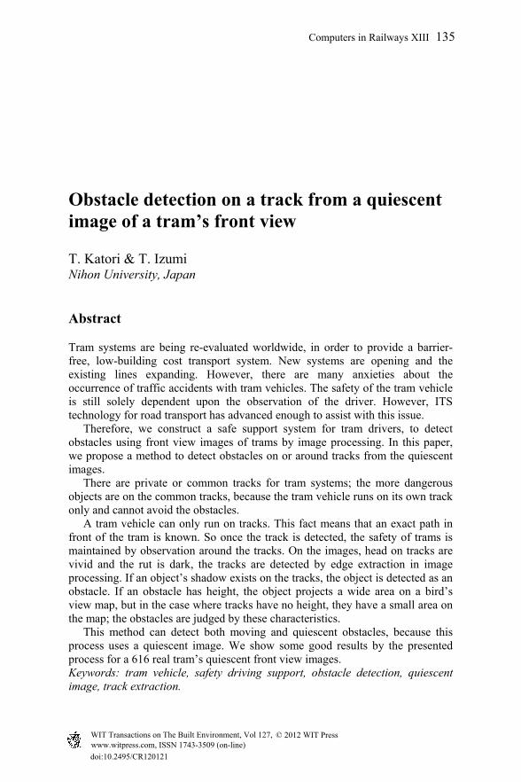
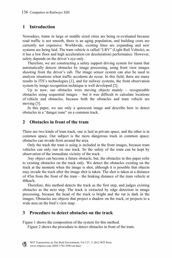
Figure 1 shows the composition of the system for this method. Figure 2 shows the procedure to detect obstacles in front of the tram.
136 Computers in Railways XIII
www.witpress.com, ISSN 1743-3509 (on-line) WIT Transactions on The Built Environment, Vol 127, © 2012 WIT Press
Obstacles Shooting from Image processing
front view
Figure 1: Composition of the system.
Figure 2: Flow chart of this method to detect obstacles.
3.1 Input of a quiescent image
A quiescent image is processed by image processing; obstacles are detected. There are no loops in this flowchart (Figure 2). A front image shot from the cab
Dark (shadow) image
Image of candidate track
Bird’s view map
Input of a quiescent image
Intensity normalization for image
Edge detection
Extraction dark (shadow) area
Back projection transfer
Determination of track
Trace for tracks
Judge to existing obstacles
Pre-processing
Computers in Railways XIII 137
www.witpress.com, ISSN 1743-3509 (on-line) WIT Transactions on The Built Environment, Vol 127, © 2012 WIT Press
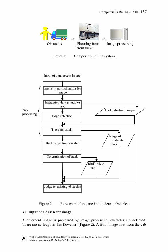
of tram is a quiescent one; it is given to the computer. To judge obstacles they should be processed in real time, but the images are saved one time for now, because it is necessary to inspect for the same source set. Figure 3 is a sample of a quiescent image. The image size is 320×240 [pixel], bitmap format, each RGB is 8 [bit] (0: dark, 255: light), direction of horizontal is shown by u; vertical is shown by v. The following shows the process for this sample image.
Figure 3: An example of an original image.
3.2 Pre-processing
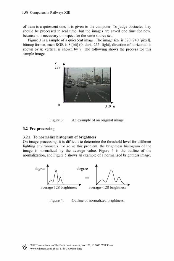
3.2.1 To normalize histogram of brightness On image processing, it is difficult to determine the threshold level for different lighting environments. To solve this problem, the brightness histogram of the image is normalized by the average value. Figure 4 is the outline of the normalization, and Figure 5 shows an example of a normalized brightness image.
degree degree
⇒
average 128 brightness average=128 brightness
Figure 4: Outline of normalized brightness.
v 239
0 319 u
138 Computers in Railways XIII
www.witpress.com, ISSN 1743-3509 (on-line) WIT Transactions on The Built Environment, Vol 127, © 2012 WIT Press
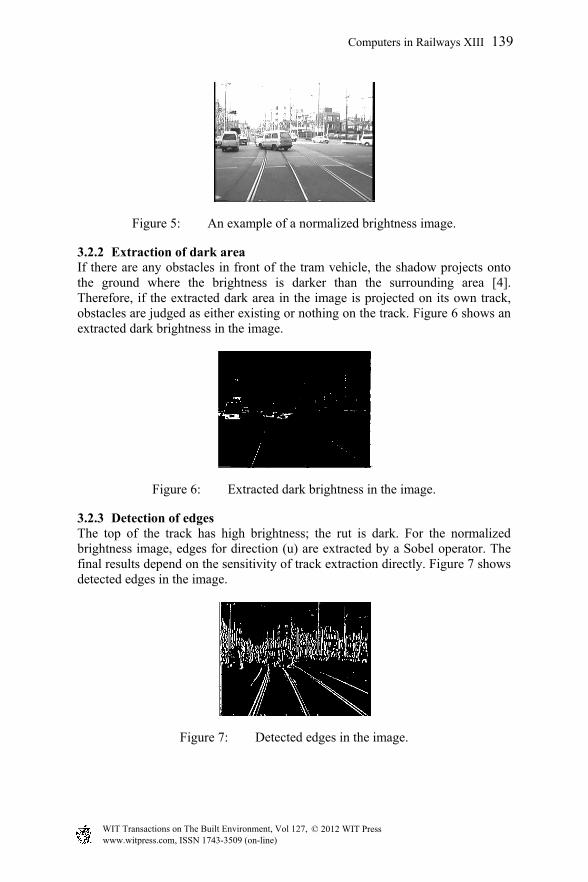
Figure 5: An example of a normalized brightness image.
3.2.2 Extraction of dark area If there are any obstacles in front of the tram vehicle, the shadow projects onto the ground where the brightness is darker than the surrounding area [4]. Therefore, if the extracted dark area in the image is projected on its own track, obstacles are judged as either existing or nothing on the track. Figure 6 shows an extracted dark brightness in the image.
Figure 6: Extracted dark brightness in the image.
3.2.3 Detection of edges The top of the track has high brightness; the rut is dark. For the normalized brightness image, edges for direction (u) are extracted by a Sobel operator. The final results depend on the sensitivity of track extraction directly. Figure 7 shows detected edges in the image.
Figure 7: Detected edges in the image.
Computers in Railways XIII 139
www.witpress.com, ISSN 1743-3509 (on-line) WIT Transactions on The Built Environment, Vol 127, © 2012 WIT Press
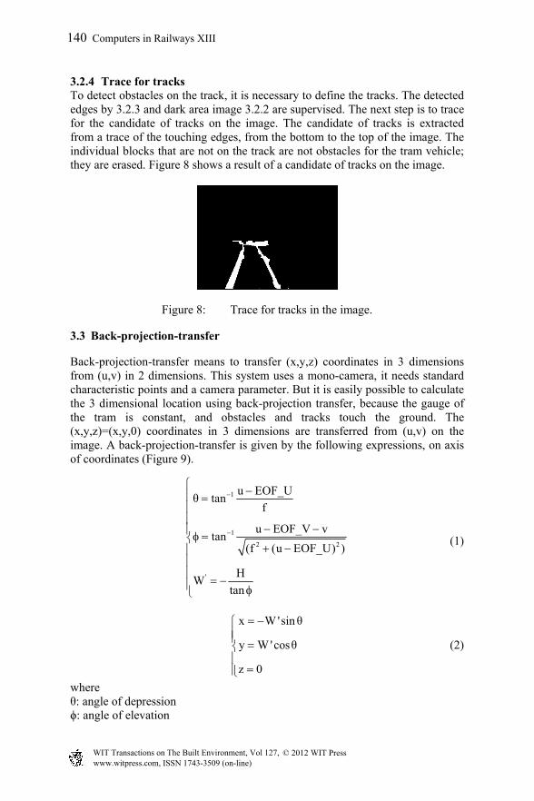
3.2.4 Trace for tracks To detect obstacles on the track, it is necessary to define the tracks. The detected edges by 3.2.3 and dark area image 3.2.2 are supervised. The next step is to trace for the candidate of tracks on the image. The candidate of tracks is extracted from a trace of the touching edges, from the bottom to the top of the image. The individual blocks that are not on the track are not obstacles for the tram vehicle; they are erased. Figure 8 shows a result of a candidate of tracks on the image.
Figure 8: Trace for tracks in the image.
3.3 Back-projection-transfer
Back-projection-transfer means to transfer (x,y,z) coordinates in 3 dimensions from (u,v) in 2 dimensions. This system uses a mono-camera, it needs standard characteristic points and a camera parameter. But it is easily possible to calculate the 3 dimensional location using back-projection transfer, because the gauge of the tram is constant, and obstacles and tracks touch the ground. The (x,y,z)=(x,y,0) coordinates in 3 dimensions are transferred from (u,v) on the image. A back-projection-transfer is given by the following expressions, on axis of coordinates (Figure 9).
1
1
2 2
'
u EOF_Uθ tan
f
u EOF_V vtan
(f (u EOF_U) )
HW
tan
(1)
x W 'sinθ
y W 'cosθ
z 0
(2)
where θ: angle of depression ϕ: angle of elevation
140 Computers in Railways XIII
www.witpress.com, ISSN 1743-3509 (on-line) WIT Transactions on The Built Environment, Vol 127, © 2012 WIT Press
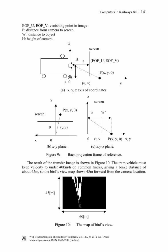
EOF_U, EOF_V: vanishing point in image F: distance from camera to screen W': distance to object H: height of camera.
(a) x, y, z axis of coordinates.
(b) x-y plane. (c) x,y-z plane.
Figure 9: Back projection frame of reference.
The result of the transfer image is shown in Figure 10. The tram vehicle must keep velocity to under 40km/h on common tracks, giving a brake distance of about 45m, so the bird’s view map shows 45m forward from the camera location.
60[m]
Figure 10: The map of bird’s view.
x, y 0
z
P(x, y, 0)(u,v
W’
screen
φ
x 0
screen
y
P(x, y, 0)
(u,v) θ
Hf
screen
x 0
z
P(x, y, 0)
(EOF_U, EOF_V)
(u, v) y
45[m]
Computers in Railways XIII 141
www.witpress.com, ISSN 1743-3509 (on-line) WIT Transactions on The Built Environment, Vol 127, © 2012 WIT Press
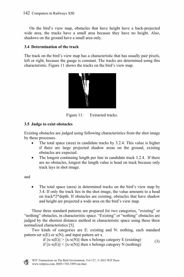
On the bird’s view map, obstacles that have height have a back-projected wide area, the tracks have a small area because they have no height. Also, shadows on the ground have a small area only.
3.4 Determination of the track
The track on the bird’s view map has a characteristic that has usually pair pixels, left or right, because the gauge is constant. The tracks are determined using this characteristic. Figure 11 shows the tracks on the bird’s view map.
Figure 11: Extracted tracks.
3.5 Judge to exist obstacles
Existing obstacles are judged using following characteristics from the shot image by these processes.
The total space (area) in candidate tracks by 3.2.4. This value is higher if there are large projected shadow areas on the ground, existing obstacles are expected.
The longest continuing length per line in candidate track 3.2.4. If there are no obstacles, longest the length value is head on track because only track lays in shot image.
and
The total space (area) in determined tracks on the bird’s view map by 3.4. If only the track lies in the shot image, the value amounts to a head on track*2*depth. If obstacles are existing, obstacles that have shadow and height are projected a wide area on the bird’s view map.
These three standard patterns are prepared for two categories, “existing” or
“nothing” obstacles, in characteristic space. “Existing” or “nothing” obstacles are judged by the shortest distance method in characteristic space using these three normalized characteristics [5].
Two kinds of categories are E: existing and N: nothing, each standard pattern set x(E) or x(N), and input pattern set x.
if ||x-x(E)|| > ||x-x(N)|| then x belongs category E (existing) if ||x-x(E)|| < ||x-x(N)|| then x belongs category N (nothing)
(3)
142 Computers in Railways XIII
www.witpress.com, ISSN 1743-3509 (on-line) WIT Transactions on The Built Environment, Vol 127, © 2012 WIT Press
4 Results and considerations
We describe and show results of obstacle detection by the proposed method for the real front view image of the tram. We apply this method for the Toden–Arakawa-line in Tokyo. There are common and private tracks; we apply the proposed method to common track sections only. Subject images for the proposed procedure are quiescent images, the frame rate is 1 [fps], numbers of images are 616 [frames]. “Existing” obstacles are 287 [frames], “nothing” are 329 [frames]. Table 1 shows the relation of the right rate for obstacle detection.
Table 1: Result of obstacles detection.
Check by eyes\proposed method
Number of images
Existing Nothing Right rates [%]
existing 287 233 54 81.2 nothing 329 60 269 81.8
All of the right rates are 81.5[%], this value is not so high. Because of three characteristic values:
total space (area) in tracks candidate longest continuing length per line in tracks candidate total space (area) in the determined tracks on the bird’s view image
is not independent, the relation to each other, and about 20% of the samples are mixed in characteristic space. To improve the right rates, it will be necessary to adopt new independent characteristics. The following are resulting images and considerations for each class.
4.1 Existing for existing obstacles
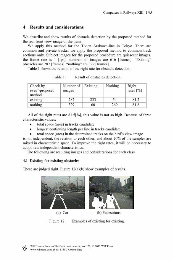
These are judged right. Figure 12(a)(b) show examples of results.
(a) Car (b) Pedestrians
Figure 12: Examples of existing for existing.
Computers in Railways XIII 143
www.witpress.com, ISSN 1743-3509 (on-line) WIT Transactions on The Built Environment, Vol 127, © 2012 WIT Press
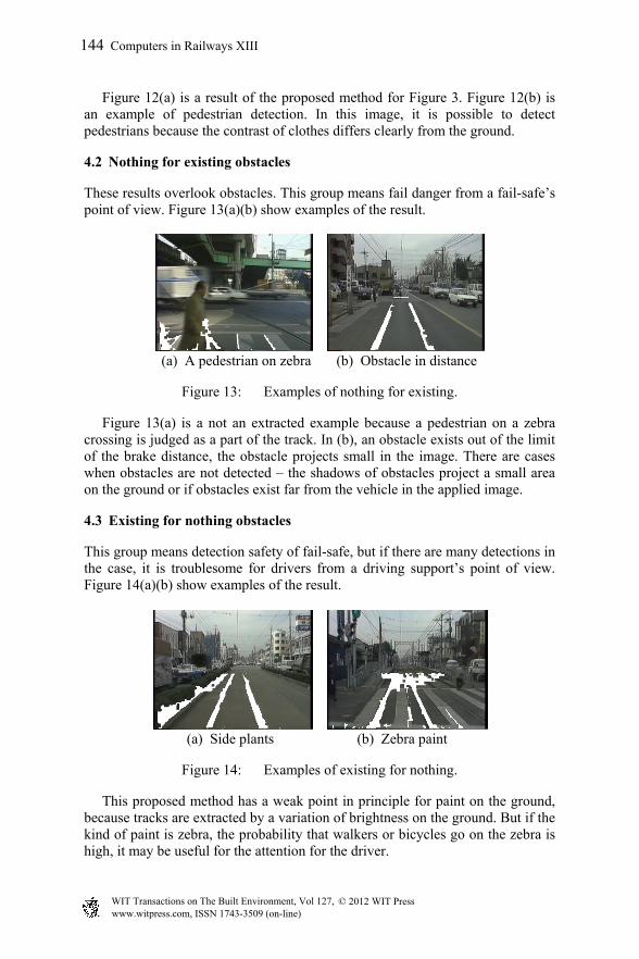
Figure 12(a) is a result of the proposed method for Figure 3. Figure 12(b) is an example of pedestrian detection. In this image, it is possible to detect pedestrians because the contrast of clothes differs clearly from the ground.
4.2 Nothing for existing obstacles
These results overlook obstacles. This group means fail danger from a fail-safe’s point of view. Figure 13(a)(b) show examples of the result.
(a) A pedestrian on zebra (b) Obstacle in distance
Figure 13: Examples of nothing for existing.
Figure 13(a) is a not an extracted example because a pedestrian on a zebra crossing is judged as a part of the track. In (b), an obstacle exists out of the limit of the brake distance, the obstacle projects small in the image. There are cases when obstacles are not detected – the shadows of obstacles project a small area on the ground or if obstacles exist far from the vehicle in the applied image.
4.3 Existing for nothing obstacles
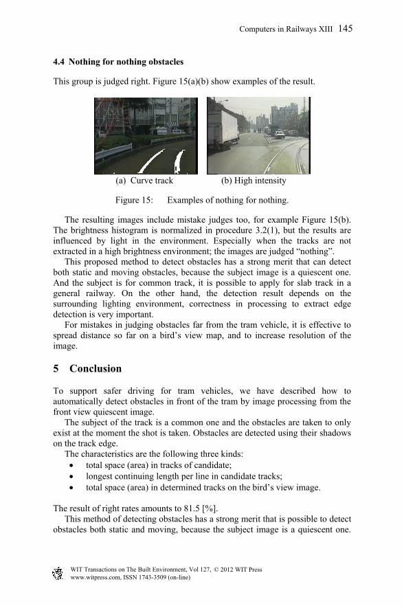
This group means detection safety of fail-safe, but if there are many detections in the case, it is troublesome for drivers from a driving support’s point of view. Figure 14(a)(b) show examples of the result.
(a) Side plants (b) Zebra paint
Figure 14: Examples of existing for nothing.
This proposed method has a weak point in principle for paint on the ground, because tracks are extracted by a variation of brightness on the ground. But if the kind of paint is zebra, the probability that walkers or bicycles go on the zebra is high, it may be useful for the attention for the driver.
144 Computers in Railways XIII
www.witpress.com, ISSN 1743-3509 (on-line) WIT Transactions on The Built Environment, Vol 127, © 2012 WIT Press
4.4 Nothing for nothing obstacles
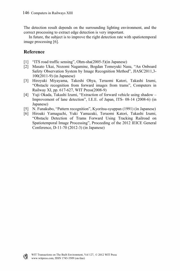
This group is judged right. Figure 15(a)(b) show examples of the result.
(a) Curve track (b) High intensity
Figure 15: Examples of nothing for nothing.
The resulting images include mistake judges too, for example Figure 15(b). The brightness histogram is normalized in procedure 3.2(1), but the results are influenced by light in the environment. Especially when the tracks are not extracted in a high brightness environment; the images are judged “nothing”. This proposed method to detect obstacles has a strong merit that can detect both static and moving obstacles, because the subject image is a quiescent one. And the subject is for common track, it is possible to apply for slab track in a general railway. On the other hand, the detection result depends on the surrounding lighting environment, correctness in processing to extract edge detection is very important. For mistakes in judging obstacles far from the tram vehicle, it is effective to spread distance so far on a bird’s view map, and to increase resolution of the image.
5 Conclusion
To support safer driving for tram vehicles, we have described how to automatically detect obstacles in front of the tram by image processing from the front view quiescent image. The subject of the track is a common one and the obstacles are taken to only exist at the moment the shot is taken. Obstacles are detected using their shadows on the track edge. The characteristics are the following three kinds:
total space (area) in tracks of candidate; longest continuing length per line in candidate tracks; total space (area) in determined tracks on the bird’s view image.
The result of right rates amounts to 81.5 [%]. This method of detecting obstacles has a strong merit that is possible to detect obstacles both static and moving, because the subject image is a quiescent one.
Computers in Railways XIII 145
www.witpress.com, ISSN 1743-3509 (on-line) WIT Transactions on The Built Environment, Vol 127, © 2012 WIT Press
The detection result depends on the surrounding lighting environment, and the correct processing to extract edge detection is very important. In future, the subject is to improve the right detection rate with spatiotemporal image processing [6].
Reference
[1] “ITS road traffic sensing”, Ohm-sha(2005-5)(in Japanese) [2] Masato Ukai, Nozomi Nagamine, Bogdan Tomoyuki Nasu, “An Onboard
Safety Observation System by Image Recognition Method”, JIASC2011,3-100(2011-9) (in Japanese)
[3] Hiroyuki Miyayama, Takeshi Ohya, Teruomi Katori, Takashi Izumi, “Obstacle recognition from forward images from trams”, Computers in Railway XI, pp. 617-627, WIT Press(2008-9)
[4] Yuji Okada, Takashi Izumi, “Extraction of forward vehicle using shadow –Improvement of lane detection”, I.E.E. of Japan, ITS- 08-14 (2008-6) (in Japanese)
[5] N. Funakubo, “Pattern recognition”, Kyoritsu-syuppan (1991) (in Japanese) [6] Hiroaki Yamaguchi, Yuki Yamazaki, Teruomi Katori, Takashi Izumi,
“Obstacle Detection of Trams Forward Using Tracking Railroad on Spatiotemporal Image Processing”, Proceeding of the 2012 IEICE General Conference, D-11-70 (2012-3) (in Japanese)
146 Computers in Railways XIII
www.witpress.com, ISSN 1743-3509 (on-line) WIT Transactions on The Built Environment, Vol 127, © 2012 WIT Press