survey 3d laser scanner - carnegie mellon university 3d digitizing mechanical coordinate measuring...
TRANSCRIPT
Professor Kenji ShimadaComputer Integrated Engineering Lab.
Carnegie Mellon
Survey on3D Digitizing and Reverse Engineering
with Laser Scanner
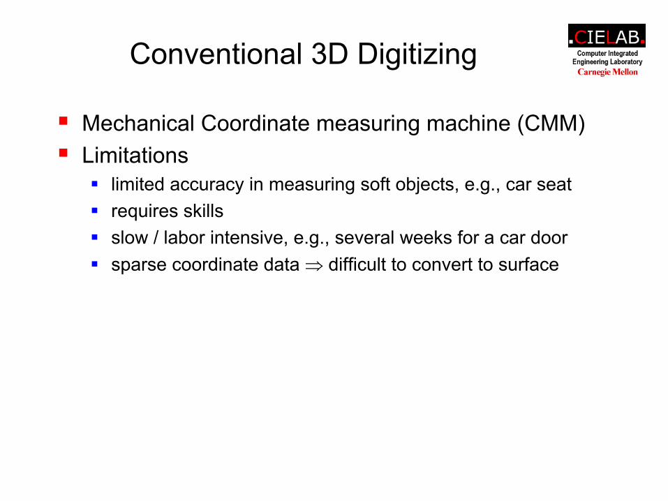
Conventional 3D Digitizing
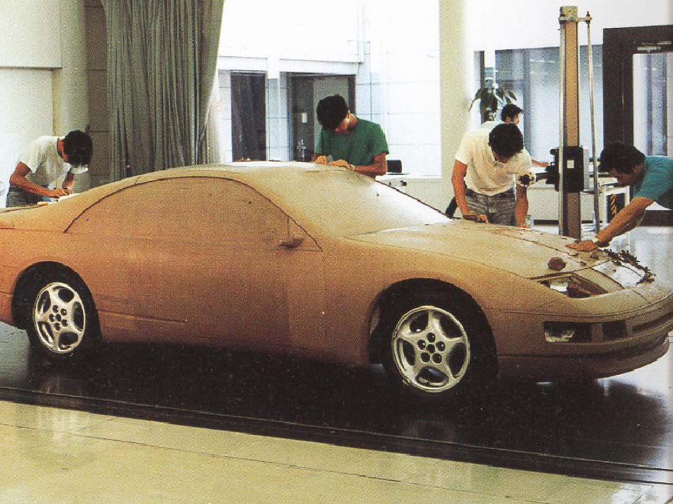
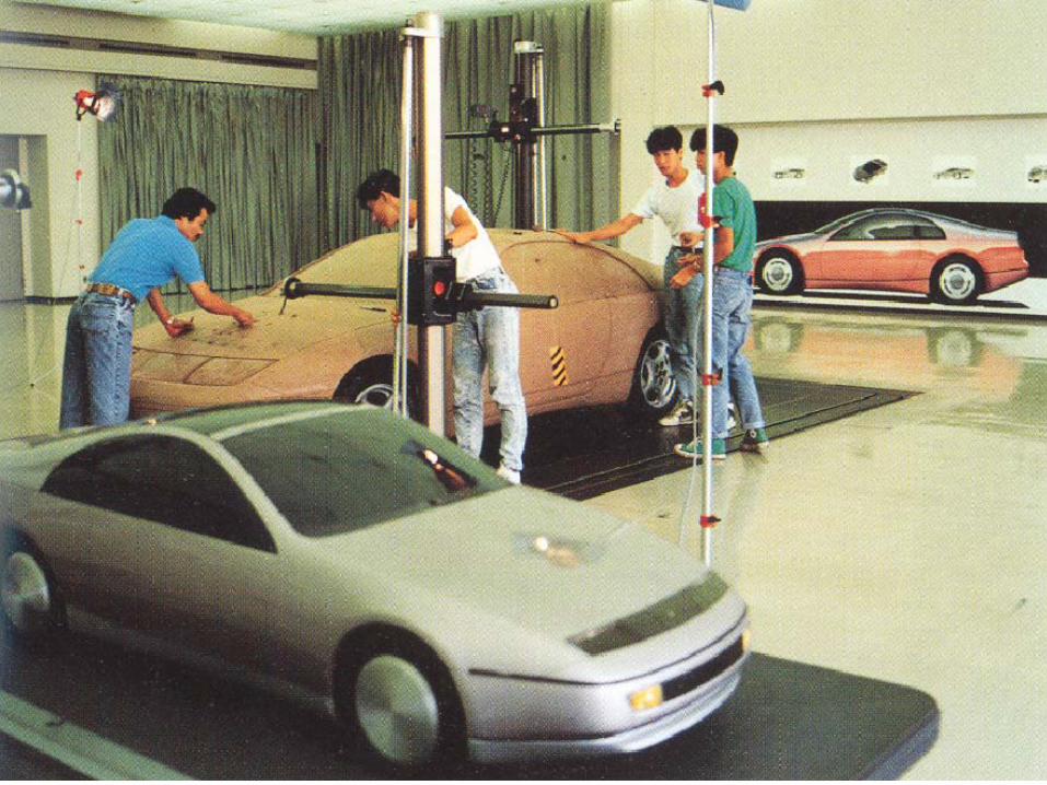
Mechanical Coordinate measuring machine (CMM)Limitations
limited accuracy in measuring soft objects, e.g., car seatrequires skillsslow / labor intensive, e.g., several weeks for a car doorsparse coordinate data ⇒ difficult to convert to surface
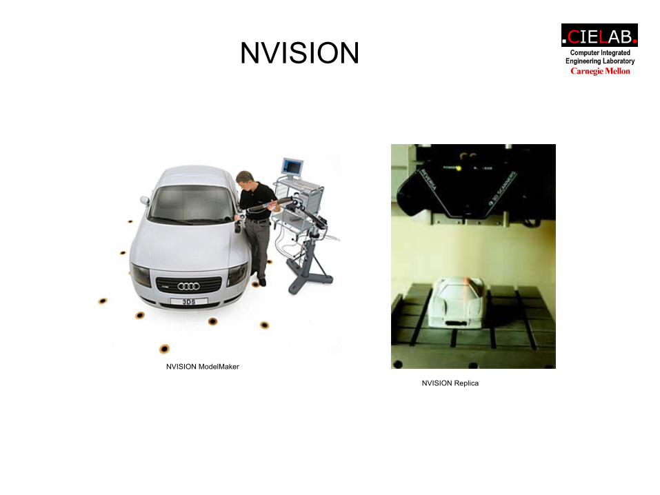
NVISION
NVISION ModelMaker
NVISION Replica
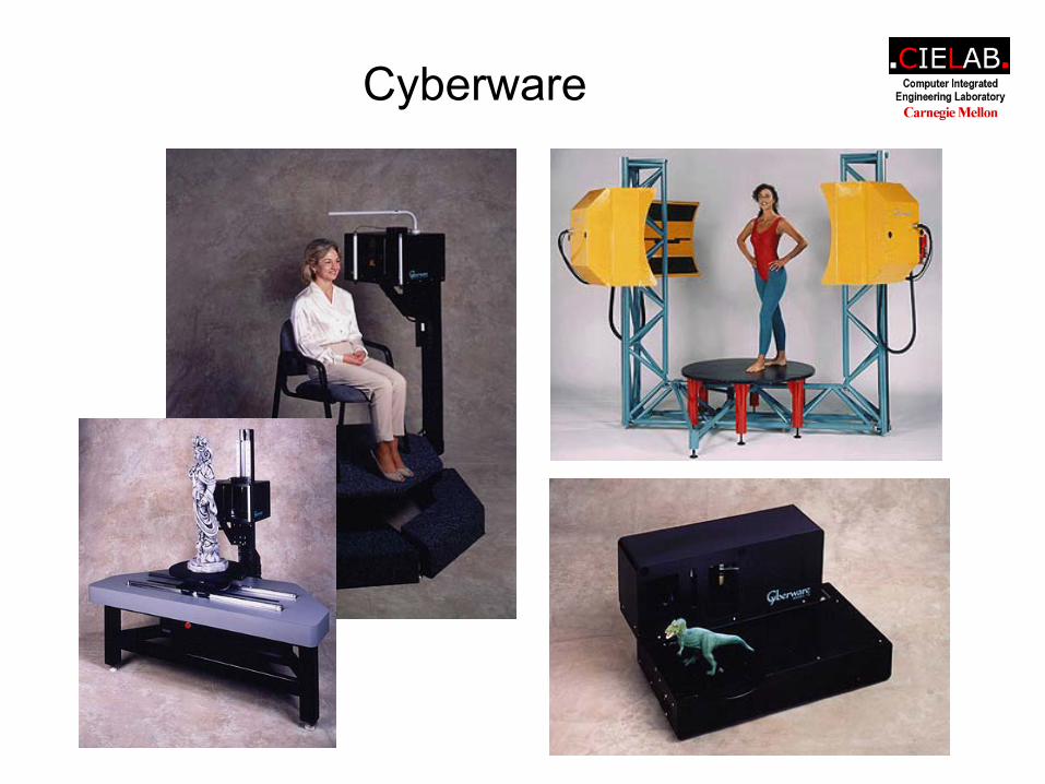
Cyberware
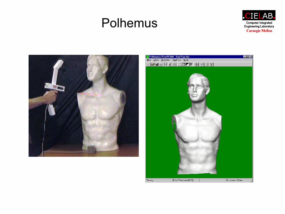
Polhemus
Laser Scanner Advantages
Non-contactDense, highly accurate coordinate dataFast scanningPortableEase of use
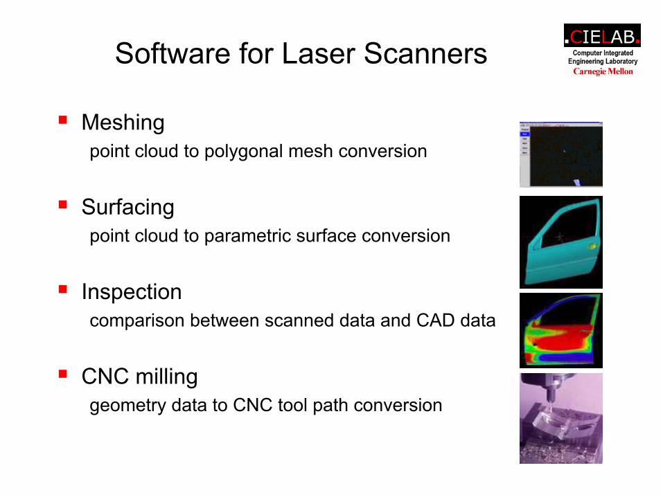
Software for Laser Scanners
Meshingpoint cloud to polygonal mesh conversion
Surfacingpoint cloud to parametric surface conversion
Inspectioncomparison between scanned data and CAD data
CNC milling geometry data to CNC tool path conversion
3D Laser Scanners in Automobile Industry
Targetcar body, interior, clay model
Applicationshigh-accuracy measurement
obtain thorough, quantitative descriptions of competitors' vehicles, e.g., width, height, wheelbase, and the layout of the interior space
digitizing prototype model (e.g., clay model) geometryreverse engineering
producing a CAD model from a physical product
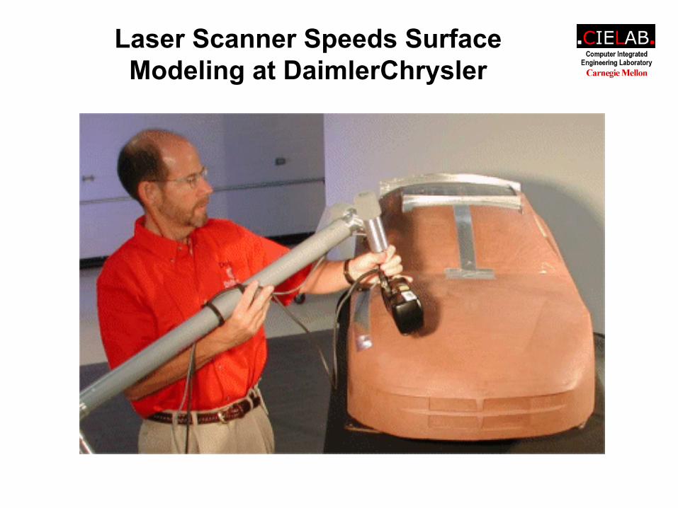
Laser Scanner Speeds Surface Modeling at DaimlerChrysler
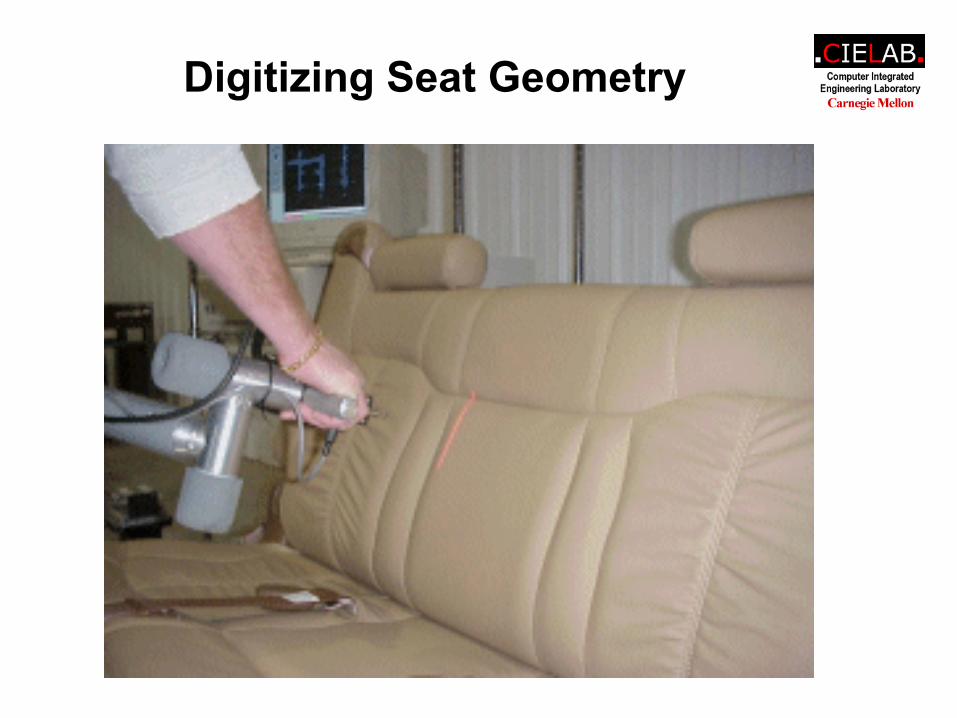
Digitizing Seat Geometry
Laser Inspection Saves $84,000 in Template Costs, Cuts Validation Time
for PT Cruiser Seats
Laser Scanning Reduces Reverse Engineering Time at Phantom Works
Laser Scanner Speeds Surface Modeling at DaimlerChrysler
The use of a laser scanner speeds the creation of surface models at DaimlerChrysler by providing a highly dense, highly accuratepoint cloud from which to construct digital surfaces. The automaker's Vehicle Measurement Lab scans car bodies, interiors, and clay prototypes to support the design process. The resulting coordinate data is imported into a CAD system and converted into surfaces. Previous scanning devices-a coordinate measuring machine (CMM) and a mechanical digitizer-captured relatively few coordinate locations, making the construction of surfaces very labor-intensive. By switching to a laser scanner, the lab now captures millions of x, y, z coordinates quickly, giving designers a thorough definition of an object's shape and making the job of constructing surfaces go much faster. Another advantage of the laser scanner is that it captures coordinate locations without touching the object. This makes it possible to scan clay models without marking them, and to scan soft objects such as leather seats more accurately.
DaimlerChrysler's Vehicle Measurement Lab supports the company's design efforts in several ways. Its main role is to provide thorough, quantitative descriptions of competitors' vehicles. This information is used by designers when they are creating cars for new markets. The lab provides measurements such as width, height, wheelbase, and so on as well as the layout of the interior space so DaimlerChrysler designers can see how other automakers addressed certain market needs. "We're always benchmarking against competitors," explains Donald Misson, supervisor of the Vehicle Measurement Lab. "We're able to get some design data from the organizations we belong to, but we've found that but the most accurate way to evaluate competitors' vehicles is to measure them ourselves."
The Vehicle Measurement Lab also measures the clay models used by designers during the conceptual stage of vehicle development. While DaimlerChrysler uses electronic CATIA models as the masters for development of new vehicle designs, clay models are still used extensively, especially early in the design process. Conceptual designs are modeled in Alias/Wavefront's industrial design software, Studio. Clay models are then sculpted from the Studio models. Designers physically fine-tune the clay models until they have the precise shape they want. That shape must then be captured digitally for import into CATIA. Although DaimlerChrysler's design office has its own measurement lab that handles most of this digitizing work, the Vehicle Measurement Lab takes on the design lab's overload.
The Vehicle Measurement Lab's third role involves supporting DaimlerChrysler's racing efforts. Wind tunnel testing is used extensively by the racing group to improve vehicle aerodynamics. The lab measures the clay models used in the wind tunnel tests. Similar to the design process for consumer vehicles, designers of the racecars refine clay models until they have the shape they want. In this case, they are modifying the models in response to the wind tunnel results to improve aerodynamic performance. The measurement lab captures the shape of the modified models so the data can be used in CATIA.
Past measurement methods
In the past, the Vehicle Measurement Lab used either a CMM or a mechanical digitizer to measure and digitize competitors' vehicles and clay models. Both the CMM and the mechanical digitizer are contact devices, which means the technician must physically touch the object with a probe to record the x, y, z coordinate location of each point. Having to touch the object causes problems when digitizing clay models because it makes marks in the soft clay. A contact device also makes it difficult to accurately measure something very soft, such as a leather seat. Touching this type of surface, even very lightly, causes it to depress. Since it isn't possible for a technician to depress each point to the same exact degree, measurements of soft objects are prone to inaccuracy.
Even with firmer objects, accuracy was always a concern with these devices because the skill of the operator affects the measurements to such a large extent. With the CMM, for example, if the operator loses contact with the part surface for an instant, accuracy suffers. Similarly, with the mechanical digitizer, the technician must be highly trained and even when he works carefully, there can still be a great deal of variability in the data based on his influence. Aside from operator influence, a CMM machine is capable of achieving the required level accuracy, but another limitation is that it is not well suited to the task of scanning complete surfaces. The operator must carefully move the probe of the machine all over the part. This takes a lot of time, several weeks typically for an automotive door, which raises costs since this process ties up a high burden rate machine.
The other significant limitation posed by contact devices stems from the type of data they generate. Since the effort of touching each coordinate location is so time-consuming, the level of data that is collected can be less than what the designers need. "Even if you scan every 50 millimeters, you can miss some detail of the surface," says Misson. The graphical result of a scan with a contact device is a series of sections. Designers must generate surfaces from the sections. Although this works well enough with simple surfaces since they can extrude from the lines and curves, it is not effective for complex shapes such as a car seat or body since the area in between the sections is not a straight line. As a result, constructing CAD surfaces from scanned data was a very labor-intensive process.
These limitations led Misson and his colleagues to evaluate non-contact devices for data capture. After evaluating the products on the market, they decided that the system that best fit their needs was a laser scanner called the ModelMaker from NVision, Irving, Texas. The major components of the ModelMaker system are a 3D laser sensor, a mechanical digitizer on which the sensor is attached, a PC, and software that extracts, displays, and manipulates the data. The software was one of the main reasons the lab chose this system, according to Mission. "We were very impressed with how the software simplified the act scanning, by removing duplicate data for example, and by how it can reduce the data size to a user-selected density," he says.
Non-contact process
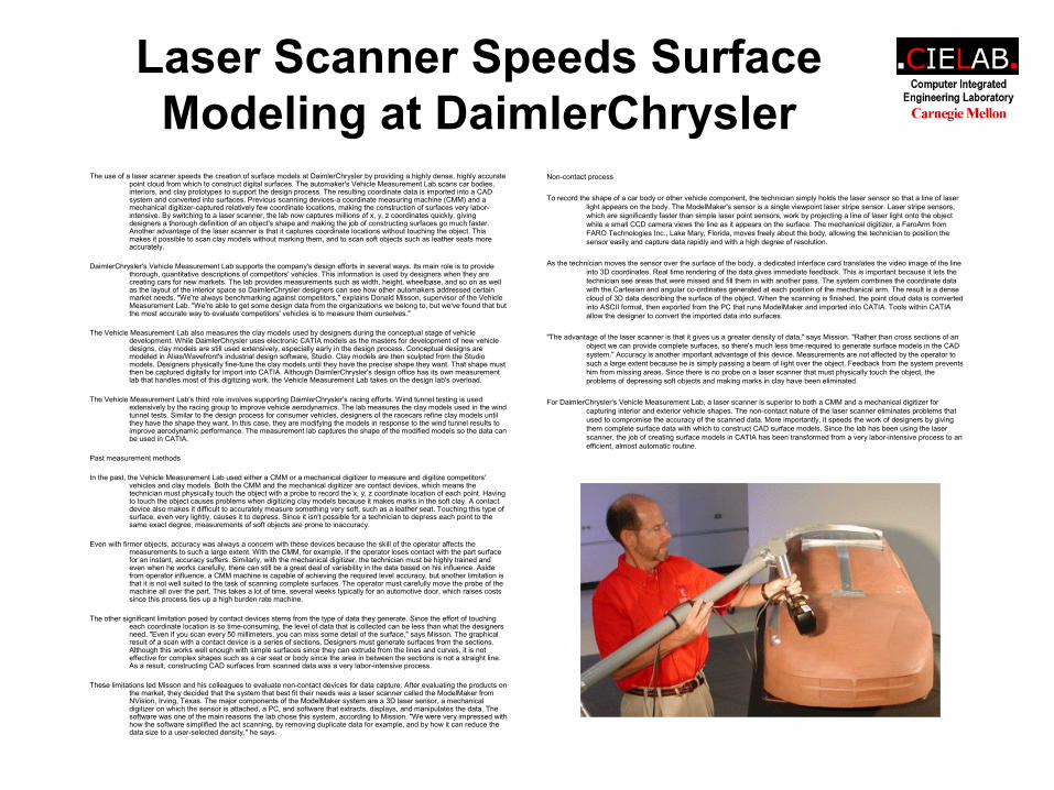
To record the shape of a car body or other vehicle component, the technician simply holds the laser sensor so that a line of laser light appears on the body. The ModelMaker's sensor is a single viewpoint laser stripe sensor. Laser stripe sensors, which are significantly faster than simple laser point sensors, work by projecting a line of laser light onto the object while a small CCD camera views the line as it appears on the surface. The mechanical digitizer, a FaroArm from FARO Technologies Inc., Lake Mary, Florida, moves freely about the body, allowing the technician to position the sensor easily and capture data rapidly and with a high degree of resolution.
As the technician moves the sensor over the surface of the body, a dedicated interface card translates the video image of the line into 3D coordinates. Real time rendering of the data gives immediate feedback. This is important because it lets the technician see areas that were missed and fill them in with another pass. The system combines the coordinate data with the Cartesian and angular co-ordinates generated at each position of the mechanical arm. The result is a dense cloud of 3D data describing the surface of the object. When the scanning is finished, the point cloud data is converted into ASCII format, then exported from the PC that runs ModelMaker and imported into CATIA. Tools within CATIA allow the designer to convert the imported data into surfaces.
"The advantage of the laser scanner is that it gives us a greater density of data," says Mission. "Rather than cross sections of an object we can provide complete surfaces, so there's much less time required to generate surface models in the CAD system." Accuracy is another important advantage of this device. Measurements are not affected by the operator to such a large extent because he is simply passing a beam of light over the object. Feedback from the system prevents him from missing areas. Since there is no probe on a laser scanner that must physically touch the object, the problems of depressing soft objects and making marks in clay have been eliminated.
For DaimlerChrysler's Vehicle Measurement Lab, a laser scanner is superior to both a CMM and a mechanical digitizer for capturing interior and exterior vehicle shapes. The non-contact nature of the laser scanner eliminates problems that used to compromise the accuracy of the scanned data. More importantly, it speeds the work of designers by giving them complete surface data with which to construct CAD surface models. Since the lab has been using the laser scanner, the job of creating surface models in CATIA has been transformed from a very labor-intensive process to an efficient, almost automatic routine.
Laser Scanner Saves Lear Thousands
With 300 facilities worldwide, Lear Corp. (Southfield, MI) a supplier of automotive interiors, needed to improve inspection efficiency and overall accuracy of new automobile seats. Seats are checked for product approval and quality control during the design and manufacturing processes. In the past, the inspection was done by comparing a sample seat to a series of contoured plastic templates -- typically about eight per seat -- indicating the original styling guidelines. The problem was the cost of producing the templates and the inspection stand.
A Set of templates is $2,000. Multiply that by the number of different seat configurations -- some automobiles can have as many as 19 different configurations. Each configuration is digitized using a coordinate measuring machine or laser scanner. The scanning cost of $103,600 covers all the different seat configurations. The surface data obtained by scanning was use to machine the seven or eight plastic templates representing critical seat areas.
In addition, duplicate sets of templates were purchased for $1,600 per set, because the same seats are produced and inspected at more than one Lear facility. For a seat program with 19 configurations, the cost for the templates was $70,000, and did not include the cost for the inspection stand. One stand costs about $22,000, and as many as five different stands could be needed for one seat inspection. When the seat was being produced at two Lear facilities, 10 stands were needed, for a total cost of $220,000.
When a seat was placed next to the templates, a lattice arrangement representative of the seat's critical contours, it was required to line up to within 6 millimeters. By using a wand with a 16 millimeter ball on one end and a 4 millimeter ball on the other, acceptable seat contour quickly could be checked; if the 16 millimeter ball passed between the seat and templates, the seat contour was too great, or if the 4 millimeter ball didn't pass through, then the seat contour was too close. This method proved a quick go-no go check of the seat contour. If the seat varied too far from the standard, the design or production process was revised and another seat was built and inspected.
In an attempt to reduce costs, Lear management investigated a number of other inspection technologies, ranging in price from $40,000 to $248,000. These systems used either laser or white light scanning techniques to capture the shapes of existing seats. White light scanning was vetoed because the system was not stable enough for the factory environment, needed a highly skilled operator, was too expensive, and did not scan body coordinates. The small, inexpensive laser systems also were ruled out because not enough laser power was produced to scan dark objects, and these systems were not rugged enough to survive in the plant environment.
The only system that met Lear's requirements was the ModelMaker from NVision, (Dallas, TX). The major components of the Model-Maker system are a 3-D laser sensor, an arm or position-sensing device on which the sensor it attached, the PC, and the software that extracts, displays, and manipulates the data. The model maker has a single viewpoint laser stripe and sensing capabilities to capture 3-D data. Laser stripe sensors project a light of laser light onto the object while a small charged coupled device camera views the line as it appears. A dedicated interface card translates the video into more than 400 3-D coordinates, allowing for a maximum data capture rate of 10,000 points per second and resulting in a dense cloud of 3-D data that accurately describes the surface of the object.
The ModelMaker can be configured with several position-sensing mechanisms. Lear chose the FaroArm from FARO Technologies Inc., (Lake Mary, FL), over competing products because the FaroArm offered 7 degrees of freedom rather than the 6 degrees most position sensing devices offer. The extra range of motion makes it possible for an operator to reach any point on a seat for measurement.
To use the ModelMaker, an operator locks the seat into the stand as before, but now that templates are no longer being used, a stand costs $15,000 rather than $22,000 -- a savings of $70,000 on typical order of 10 stands -- because it does not require the mechanisms that hold templates in place.
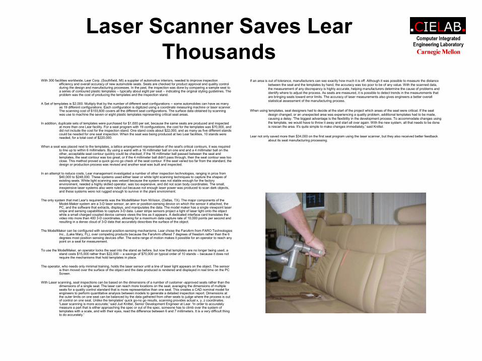
The operator, who needs only minimal training, holds the laser sensor until a line of laser light appears on the object. The sensor is then moved over the surface of the object and the data produced is rendered and displayed in real time on the PC Screen.
With Laser scanning, seat inspections can be based on the dimensions of a number of customer -approved seats rather than the dimensions of a single seat. The laser can reach more locations on the seat, averaging the dimensions of multiple seats for a quality control standard that is more representative than one seat. This creates a CAD nominal model for engineers to perform quantitative analysis between models to generate a detailed inspection report. Dimensions at the outer limits on one seat can be balanced by the data gathered from other seats to judge where the process is out of control on one seat. Unlike the templates' quick go-no go results, scanning provides actual x, y, z coordinates. 'Laser scanning is more accurate,' said Jud Knittel, Senior Development Engineer at Lear. 'In order to accurately measure a part that is either approaching the spec or out of the spec, someone has to climb over the system of templates with a scale, and with their eyes, read the difference between 6 and 7 millimeters. It is a very difficult thing to do accurately.'
If an area is out of tolerance, manufacturers can see exactly how much it is off. Although it was possible to measure the distance between the seat and the templates by hand, the accuracy was too poor to be of any value. With the scanned data, the measurement of any discrepancy is highly accurate, helping manufacturers determine the cause of problems and identify where to adjust the process. As seats are measured, it is possible to detect trends in the measurements that are bringing seats toward error limits. The accuracy of laser measurements also gives engineers a better overall statistical assessment of the manufacturing process.
When using templates, seat designers had to decide at the start of the project which areas of the seat were critical. If the seat design changed, or an unexpected area was experiencing a quality problem, additional templates had to be made, causing a delay. 'The biggest advantage is the flexibility in the development process. To accommodate changes using the template, we would have to throw it away and start all over again. With the new system, all that needs to be done is rescan the area. It's quite simple to make changes immediately,' said Knittel.
Lear not only saved more than $34,000 on the first seat program using the laser scanner, but they also received better feedback about its seat manufacturing processing.
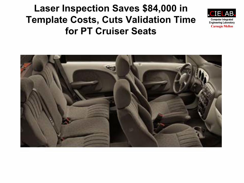
Laser Inspection Saves $84,000 in Template Costs, Cuts Validation Time
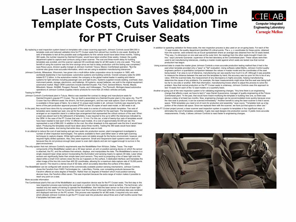
for PT Cruiser SeatsBy replacing a seat inspection system based on templates with a laser scanning approach, Johnson Controls saved $84,000 in
template costs and reduced validation time for PT Cruiser seats from almost four months to one week. Building 24 sets of templates to test all the possible seat configurations for this vehicle would have taken three months. Testing 360 seats, the number required by DaimlerChrysler, would have taken another three weeks. Instead, the quality department opted to capture seat contours using a laser scanner. The cost and three-month delay for building templates was avoided, and the scanner captured 3D coordinate data for all 360 seats in only one week. "The main benefit of using the scanner was the time savings since we had to delay production until the testing was completed," says Rosa Leyva, division quality manger at Johnson Controls' Toluca, Mexico Comfortseat operation. "But the scanner also gives more accurate information, which we are using to establish manufacturing tolerances."
Johnson Controls, Milwaukee, Wisconsin, has grown into a multi-billion dollar corporation since its inception in 1885, with worldwide leadership in two businesses: automotive systems and building controls. Overall company sales for 2000 totaled $17.2 billion. In the automotive market, the company is the global market leader in seating and interior systems for light vehicles including passenger cars and light trucks. Systems supplied include seating, overhead, door, instrument panels, storage, electronics, and batteries. All systems, except batteries, are sold to the original equipment automotive market. Major OEM customers include DaimlerChrysler, Fiat, Ford, General Motors, Honda, Mazda, Mitsubishi, Nissan, NUMMI, Peugeot, Renault, Toyota, and Volkswagen. The Plymouth, Michigan-based automotive operations of Johnson Controls supplies interior products for more than 20 million vehicles annually.
Testing for PPAP Johnson Control's Comfortseat plant in Toluca, Mexico was awarded the contract to design and manufacture seats for
DaimlerChrysler's popular PT Cruiser. The car itself is assembled at a DaimlerChrysler plant in the same city. The PT Cruiser has four different seats: the driver's, the front passenger's, and two rear seat options. Each of these four seats is available in three types of fabric, for a total of 12 unique seat models in all. Johnson Controls was required by the terms of the part production approval process (PPAP) to test 30 copies of each seat model, or 360 seats in all.
In the past, they would have done this by comparing each of the seats to a series of contoured plastic templates. Two sets of templates were needed per seat, one set for the seat cushion and another for the seat back. The templates were arranged on an inspection stand in a lattice-type arrangement that represented the critical contours of the seat. When a seat was placed next to the latticework of templates, it was required to line up to within the tolerances indicated by the OEM. In the case of the PT Cruiser that was +/- 12 mm. For this car, a total of twenty-four sets of templates would have been needed to test each of the 12 different seat models. At a cost of approximately $3,500 per set, this represented a cost of $84,000. In addition to the cost, the other drawback to this approach was the time it would have taken. Producing the templates would have taken about three months. Testing the 360 seats would have taken another three weeks. And during that entire time, production was on hold.
In an attempt to reduce the cost of seat testing and get new seats into production sooner, plant management investigated a number of other inspection technologies. The options available to them used either laser or white light scanning techniques to capture shapes. White light systems were not stable enough for the factory environment, however, and required highly skilled operators. Also, they were expensive. Small and inexpensive laser systems were ruled out because they do not produce enough laser power to scan dark objects and are not rugged enough to survive in the plant environment.
The only system that met Johnson Control's requirements was the ModelMaker from NVision, Dallas, Texas. The major components of the ModelMaker system are a 3D laser sensor, an arm or position-sensing device on which the sensor is attached, the PC, and the software that extracts, displays, and manipulates the data. The ModelMaker's sensor is a single viewpoint laser stripe sensor incorporating the illumination and sensing means to capture 3D data. Laser stripe sensors are significantly faster than simple laser point sensors. They work by projecting a line of laser light onto the object while a small CCD camera views the line as it appears on the surface. A dedicated interface card translates the video image of the line into more than 400 3D coordinates, allowing for a maximum data capture rate of 10,000 points per second. The result is a dense cloud of 3D data, which accurately describes the surface of the object.
The ModelMaker can be configured with several of the commercially available position-sensing mechanisms. Johnson Controls chose the FaroArm from FARO Technologies Inc., Lake Mary, Florida, over competing products because the FaroArm offered an extra degree of freedom. Rather than six degrees of freedom which most position-sensing devices have, the FaroArm offers seven. This was important because the extra range of motion makes it possible to reach any point on a seat.
More accurate information The Comfortseat plant's first use of the ModelMaker as a seat inspection device was for the PT Cruiser seats. The first step in the
new inspection process was locking the seat back or cushion into the inspection stand as before. The technician, who needed only two weeks of training to operate the ModelMaker, then held the laser sensor so that a line of laser light appeared on the seat. Then he moved the sensor over the surface of the seat while the coordinate data was rendered and displayed real-time on the PC screen. This process was repeated for all 360 seats. It required only one week, which allowed Johnson Controls to get the PT Cruiser seat into production about three and a half months sooner than if templates had been used.
In addition to speeding validation for these seats, the new inspection process is also used on an on-going basis. For each of the 12 seat models, the quality department identified 25 critical points. The x, y, z coordinates for these points, obtained from the scanner, were entered into an Excel spreadsheet where an average was obtained from the 30 seats tested. "This way, if a dimension on one seat was at the outer limit, the readings from the other seats brought it back into line," says Leonardo Quinaniar, supervisor of the test laboratory at the Comfortseat plant. These values were then used to set manufacturing tolerances, creating a master model against which seats are tested now that normal production has begun.
Using scanned data to create the master gives Johnson Controls a more accurate production testing method than it had in the past when template provided only a "pass" or "fail" evaluation. Using software called Metris, Johnson Control quality engineers perform a quantitative comparison between the values in master model and the coordinates of the seat being tested. If an area is out of tolerance, manufacturing can see exactly how much it is off. Although it was possible to measure the distance between the seat and the templates by hand, the accuracy was too poor for this to be of any value. With the scanned data, the measurement of any discrepancy is highly accurate, helping manufacturing determine the cause of any problems. For example, the laser measurements might show that the seat was being built too far to one side or another. With that information, manufacturing knows where to adjust the process to solve the problem. Now that normal production on the PT Cruiser seats is underway, Johnson Controls uses this approach to test 10 seats from each of the 12 seat models on a quarterly basis.
Another on-going use of the new inspection system is for validating engineering changes. "Any time there is an engineering change that affects a seat, we have to test it," says Daniel Guavarrama, manager of quality engineering at the TolucaComfortseat plant. "In the past, that would have meant modifying the template or building new one, so there was always a delay of at least two months. Now, engineering changes can be accommodated more quickly because once the new seat is produced, it can be scanned immediately." Another benefit to using the laser scanner is that it saves space. "With templates you need a lot of room for production and assembly," says Leyva. "Templates took up a big portion of the chassis lab space. Since we replaced them with the scanner, we have put that space to other use."
As the PT Cruiser project proved, a laser scanner seat inspection system is superior to templates in four significant ways. It eliminates the cost of templates completely. It gets new seat designs into production sooner. It yields more accurate measurements. Finally, it allows Johnson Controls to react faster to engineering changes.
Laser Inspection Saves $84,000 in Template Costs, Cuts Validation Time
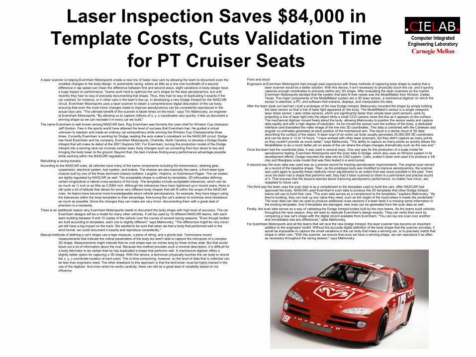
for PT Cruiser SeatsA laser scanner is helping Evernham Motorsports create a new line of faster race cars by allowing the team to document even the
smallest changes to the body design. In automobile racing, where as little as a one one-hundredth of a second difference in lap speed can mean the difference between first and second place, slight variations in body design have a huge impact on performance. Teams work hard to optimize the car's shape for the best aerodynamics, but until recently they had no way of precisely documenting that shape. Thus, they had no way of duplicating it exactly-if the car crashed, for instance, or in other cars in the team's line-up. In developing a new Dodge Intrepid for the NASCAR circuit, Evernham Motorsports uses a laser scanner to obtain a comprehensive digital description of the car body, ensuring that even the most minor changes made to improve aerodynamics can be consistently reproduced in the actual race cars. "The ultimate benefit of the scanner is faster times on the track," says Tim Malinovsky, an engineer at Evernham Motorsports. "By allowing us to capture millions of x, y, z coordinates very quickly, it lets us document a winning shape so we can recreate it in every car we build."
The name Evernham is well known among NASCAR fans. Ray Evernham was formerly the crew chief for Winston Cup champion Jeff Gordon. Few in the sports world have attained the level of success that Evernham has. He guided a virtual unknown to stardom and made an ordinary car extraordinary while winning the Winston Cup Championship three times. Currently Evernham is working for Dodge, leading the auto maker's comeback on the NASCAR circuit. Dodge has hired Evernham and his company, Evernham Motorsports, Charlotte, North Carolina, to develop a Dodge Dealer Intrepid that will make its debut at the 2001 Daytona 500. For Evernham, turning the production model of the Dodge Intrepid into a winning race car involves certain basic body changes such as converting from four doors to two and bringing the body lower to the ground. Beyond that, the task involves finding every performance advantage possible while working within the NASCAR regulations.
Rebuilding a racing dynasty According to the NASCAR rules, all vehicles have many of the same components including the transmission, steering gear,
suspension, electrical system, fuel system, and brakes. The chassis are also basically the same, a front-steer-type chassis built by one of the three dominant chassis builders: Laughlin, Hopkins, or Hutcherson-Pagan. The car bodies are tightly regulated by NASCAR as well. The acceptable shape is outlined by templates, 2D silhouettes defining certain longitudinal or lateral cross-sections of the body. The templates include acceptable tolerances, which can be as much as ½ inch or as little as 0.0060 inch. Although the tolerances have been tightened up in recent years, there is still quite a bit of latitude that allows for some very different body shapes that still fit within the scope of the NASCAR rules. As teams have become more knowledgeable about vehicle aerodynamics, for example, they have begun using the tolerances within the body templates to their advantage, fine-tuning the car's exterior to minimize wind resistance as much as possible. Since the changes they can make are very minor, documenting them with a great deal of precision is a necessity.
There is an additional reason why Evernham Motorsports needs to document the body shape with high level of accuracy. The car Evernham designs will be a model for many other vehicles. It will be used by 10 different NASCAR teams, with each team building between 9 and 15 copies of the vehicle over the course of several racing seasons. "Even though bodies are built according to templates, each one is slightly different," says Malinovsky. "The differences might be very minor yet still have a big impact on the track. We wanted to be sure that when we had a body that performed well in the wind tunnel, we could document it exactly and reproduce consistently."
Manual methods of defining a car's shape use a tape measure, a piece of string, and a plumb bob. Technicians record measurements that indicate the critical parameters of the body but aren't able to capture the intricacies of a complex 3D shape. Measurements might indicate that an oval shape was six inches long by three inches wide. But that would leave out a lot of information about the oval. Because this method provides such a minimal description, it is difficult for a body fabricator to be certain that he has duplicated a shape that performs well. A mechanical digitizer offers a slightly better option for capturing a 3D shape. With this device, a technician physically touches the car body to record the x, y, z coordinate location of each point. This is time-consuming, however, so the level of data that is collected can be less than engineers need. The other drawback to this approach is that the technician must be highly trained in the use of the digitizer. And even when he works carefully, there can still be a great deal of variability based on his influence.
Point and shoot Engineers at Evernham Motorsports had enough past experience with these methods of capturing body shape to realize that a
laser scanner would be a better solution. With this device, it isn't necessary to physically touch the car, and it quickly captures enough coordinates to precisely define any 3D shape. After evaluating the laser scanners on the market, Evernham Motorsports decided that the system that best fit their needs was the ModelMaker from NVision, Dallas, Texas. The major components of the ModelMaker system are a 3D laser sensor, a mechanical digitizer on which the sensor is attached, a PC, and software that extracts, displays, and manipulates the data.
After the team (took out had had ) built a prototype of the new Dodge Intrepid, Malinovsky recorded the shape by simply holding the laser sensor so that a line of laser light appeared on the body. The ModelMaker's sensor is a single viewpoint laser stripe sensor. Laser stripe sensors, which are significantly faster than simple laser point sensors, work by projecting a line of laser light onto the object while a small CCD camera views the line as it appears on the surface. The mechanical digitizer moved freely about the body, allowing Malinovsky to position the sensor easily and capture data rapidly and with a high degree of resolution. As he moved the sensor over the surface of the body, a dedicated interface card translated the video image of the line into 3D coordinates. This data is combined with the Cartesian and angular co-ordinates generated at each position of the mechanical arm. The result is a dense cloud of 3D data describing the surface of the object. A laser scan of an entire car body usually generates 25,000,000 3D coordinates and can be done in 12 to 14 hours. "I have worked with other laser scanners, but they didn't capture as many points so they couldn't provide as much detail," says Malinovsky. "The ability to capture so many points so quickly allows the ModelMaker to do a much better job on areas of the car where the shape changes dramatically such as the rear end."
Once the team had the coordinate data, it was used in several ways. One way was for the production of a scale model for aerodynamic testing. Evernham Motorsports sent the scan data to Dodge, which also uses an NVision system in its development efforts. Dodge imported the data into its CAD system, Catia, scaled it down and used it to produce a 3/8 clay and fiberglass scale model that was then tested in a wind tunnel.
A second way the scan data was used was as a precise record for tracking aerodynamic improvements. The original scan served as a record of the baseline shape. Then, as the prototype body was modified to improve aerodynamics, the scanner was used again to quantify these relatively minor adjustments to an extent that was never possible in the past. Then once the team had a shape that performs well, they had it laser scanned so there is a permanent and precise record of it. That ensures that the lessons learned about improving aerodynamic performance, no matter how minor, are reapplied to future cars.
The third way the team uses the scan data is as a complement to the templates used to build the cars. After NASCAR had approved the body, NASCAR used Evernham's scan data to produce the 2D templates that other Dodge Intrepidteams will use to build their cars. "The scan data serves as a complement to the templates," explains Malinovsky. "As they're building, they can look up any value they need, such as the height of the hood where it meets the windshield." The scan data can also be used to produce additional cross sections if a team feels it is missing some information in the existing templates. And if templates are damaged, new ones can be generated from the scan data as well.
Finally, the scan data serves as a way of validating the Dodge Intrepid bodies built by the race teams. As the teams build vehicles throughout the race season, they will want to replicate Evernham's design exactly. They can verify their work by comparing a new car's shape with the digital record available from Evernham. "You can lay one scan over another and immediately see any differences," adds Malinovsky.
For Evernham Motorsports and all the teams that will race the new Dodge Intrepid, the laser scanner has become an important addition to the engineers' toolkit. Without the accurate digital definition of the body shape that the scanner provides, it would be impossible to capture the small variations in the car body that make a winning car, or to precisely match that shape in other cars. "With the scanner, we ensure that once we have a winning shape, we can reproduce it as often as necessary throughout the racing season," says Malinovsky.
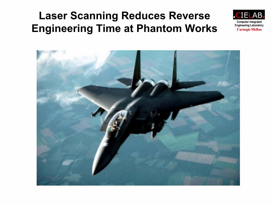
Laser Scanning Reduces Reverse Engineering Time at Phantom Works
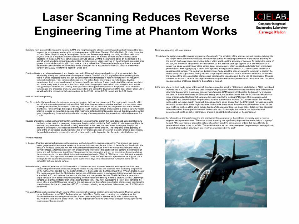
Switching from a coordinate measuring machine (CMM) and height gauges to a laser scanner has substantially reduced the time required for reverse engineering while improving accuracy at Boeing's Phantom Works facility in St. Louis, according to David Skiles, Rapid Prototype Development Technician. Reverse engineering, producing a CAD model from a physical product, is important in cases where modifications are to be made to an older aircraft as well as other situations. In the past, the most common approach was using a CMM to measure data points on the surface of the aircraft, which was time-consuming and provided limited accuracy. Laser scanning, on the other hand, generates a far greater number of data points, which improves accuracy, in less time." Using special surfacing software, scanned data can be used to create a CAD surface model of the part that is accurate to within 0.0012 inch to sheet metal surfaces and 0.0002 inch for hole position," Skiles said.
Phantom Works is an advanced research and development unit of Boeing that pursues breakthrough improvements in the affordability, quality and performance of aerospace systems. The staff of 4,500 engineers and scientists typically works in small, integrated teams that can be quickly formed and mobilized to help customers meet their toughest technical challenges. Their common challenge is to find better, faster and cheaper ways to design, develop, manufacture, test, operate and support both current and future systems. A team developing 3-D modeling, simulation and virtual reality tools, for instance, has found ways to cut design cycle times in half, eliminating the need to build costly prototype hardware and creating more producible and supportable systems in the process. Such innovative technologies and processes are being used to save time and cost in the development of the Joint Strike Fighter (JSF) as well as for the improvement of such products as the AV-8B Harrier, F/A-18 Hornet and the F-15 Eagle.
Need for reverse engineering
The St. Louis facility has a frequent requirement to reverse engineer both old and new aircraft. The need usually arises for older aircraft which were designed without benefit of CAD when they are to be repaired or modified. In some cases, mylardrawings are available, which could potentially be scanned into a CAD model, but this process has some inherent drawbacks. For one things, the original drawings are in 2D, making it difficult or impossible to create a 3D CAD model which is required for many tasks, such as CNC machining or finite element analysis. Second, the drawings have often been changed many times so that there is often no way of knowing whether the physical aircraft is revision A or B or C or D.
Reverse engineering is also an important tool for current and even experimental aircraft that were designed using the latest CADmethods. In this case, it is necessary to compare the physical aircraft to the CAD model. An interference problem, for example, may arise when the aircraft is being assembled. In this case, the need arises to compare the physical aircraft to the original CAD design to determine the exact cause of the problem. The complexity of the geometry of state-of-the art aerospace structures makes this a very challenging task. Even when a specific problem doesn't exist, the need often arises to compare the aircraft to the model in order to confirm that the design intent is being met.
Previous methods
In the past, Phantom Works technicians used two primary methods to perform reverse engineering. The simplest was to use height gauges and other manual measuring instruments to measure discrete points on the surface of the aircraft. It is difficult to inspect a contoured part with manual measurements because there is no way to document the shape of curved surfaces. A technician can get only critical dimensions such as the location of hole centers, the diameters of holes, and wall thicknesses. In addition, this approach is time-consuming and only as accurate as the person taking the measurements. It is also difficult to inspect contoured parts with CMMs. A CMM has a probe that must physically touch the part. Although these machines can acquire data points more quickly than a person can, for a typical part it will capture only several thousand data points over several days. This relatively small number of points can not completely define a curved surface.
After researching the issue, Phantom Works came to the conclusion that laser scanners were the better option because they capture shape information without touching the model, making them fast and accurate. After evaluating the products on the market, they decided that the system that best fit their needs was the ModelMaker from NVision, Dallas, Texas. The major components of the ModelMaker system are a 3D laser sensor, a mechanical digitizer on which the sensor is attached, a PC, and software that extracts, displays, and manipulates the data. The ModelMaker's sensor is a single viewpoint laser stripe sensor incorporating the illumination and sensing means to capture 3D data. Laser stripe sensors are significantly faster than simple laser point sensors. They work by projecting a line of laser light onto the object while a small CCD camera views the line as it appears on the surface. A dedicated interface card translates the video image of the line into more than 400 3D coordinates, allowing for a maximum data capture rate of 10,000 points per second.
The ModelMaker can be configured with several of the commercially available position-sensing mechanisms. Phantom Works chose the FaroArm from FARO Technologies Inc., Lake Mary, Florida, over competing products because the FaroArm offered an extra degree of freedom. Rather than six degrees of freedom which most position-sensing devices have, the FaroArm offers seven. This was important because the extra range of motion makes it possible to reach any point on an aircraft.
Reverse engineering with laser scanner
This is how the system is used for reverse engineering of an aircraft. The portability of the scanner makes it possible to bring it to the hanger where the aircraft is located. The technician stands on a stable platform next to the aircraft. Standing on the aircraft itself could cause the structure to flex, which would spoil the accuracy of the scan. To capture the shape of the part, the technician simply holds the laser sensor so that a line of laser light appears on it. The ModelMaker'ssensor is a single viewpoint laser stripe sensor. Laser stripe sensors, which are significantly faster than simple laser point sensors, work by projecting a line of laser light onto the object while a small CCD camera views the line as it appears on the surface. The mechanical digitizer moves freely about the body, allowing the technician to position the sensor easily and capture data rapidly and with a high degree of resolution. As the technician moves the sensor over the surface of the part, a dedicated interface card translates the video image of the line into 3D coordinates. This data is combined with the Cartesian and angular co-ordinates generated at each position of the mechanical arm. The result is a dense cloud of 3D data describing the surface of the part.
In the case where no CAD model exists of the aircraft, the data is exported from the PC that runs ModelMaker in ASCII format and imported into a 3D CAD system and used to create a high-quality CAD model from the coordinate data. This model is often later transferred to a computer-assisted manufacturing (CAM) program that creates the toolpath for producing the parts. In the situation where a CAD model already exists, the data is exported from the PC that runs ModelMakerinto a program called Surfacer that compares the point cloud to the existing CAD model. This process is called registration, and it superimposes the point cloud from the scanned data onto the CAD surface model. The resulting color-coded plot shows exactly how much the collected data points deviate from the CAD model. For example, points below the surface of the model might be shown in blue while those above the surface would be shown in red. Or the user might opt to show all the points outside the client's tolerance settings in a single color. It also provides statistical information about the comparison between the two data sets. For example, the software can determine what percentage of points are out of tolerance, or provide a standard deviation value for the comparison.
Skiles said the net result is a dramatic timesaving and improvement in accuracy over the methods previously used to reverse engineer aerospace structures. "The move to laser scanning has significantly improved the productivity of our group," he said. "The laser scanner generates millions of points in about the same amount of time that it used to take to produce hundreds of points on a CMM. The result is that the we can reverse engineer the geometry of existing aircraft to much higher levels of accuracy in less time than was required in the past."