v isual slope v6 · v isual slope v6. ii ... visual slope is developed based on the most commonly...
TRANSCRIPT

A Geotechnical Engineering Design Resource
V i s u a l S l o p e , L L C w w w . v i s u a l s l o p e . c o m i n f o @ v i s u a l s l o p e . c o m
VisualSlopeV6

ii
Table of Content
Page IntroductionofVisualSlope......................................................................................................1
MainFeatures...........................................................................................................................2
VisualSlope-SlopeStabilityAnalysis.....................................................................................2
VisualSlope-SoilNailingDesign............................................................................................5
VisualSlope-ResistingPileDesign.........................................................................................6
VisualSlope-MSEWallDesign...............................................................................................8
VisualSlope-ReinforcedSlopeDesign.................................................................................11
VisualSlope-SeepageAnalysis............................................................................................12
VisualSlope-ShoringSystemDesign...................................................................................15
VisualSlope-GroundFreezingConstructionDesign...........................................................17
VisualSlope-TunnelLiningDesign......................................................................................19

1
Visual Slope, LLC.,Cincinnati, Ohio, USA
Introduction of Visual Slope The Visual Slope series, developed by Visual Slope, LLC. USA, is a new generation of geo-structural design software that consists of design modules for:
² Slope Stability Analysis ² Slope Stability Analysis due to Rainfall or Seepage ² Soil Nailing Design ² Resisting Pile Design ² MSE Wall Design ² Reinforced Slope Design ² Seepage Analysis ² Shoring Design ² Tunnel Lining Design ² Freezing Construction Design
Visual Slope is developed based on the most commonly accepted design theories, concepts and codes. Users can also modify the existing design codes or create new codes that are suitable for their countries or projects. Therefore, Visual Slope can be used directly by engineers of different countries. Visual Slope uses convenient drawing procedures similar to AutoCAD to help users establish analytical models, which allows a detailed and accurate modeling of a complicated project. Visual Slope also includes a database that allows users to easily store and reuse commonly used material properties. No matter how
2
complicated the problem is (such as one that involves different design modules), Visual Slope only uses one simple input file, which makes communication among the users much easier. Geotechnical design firms, government agencies, and universities worldwide have used Visual Slope as a design or teaching software. In addition, numerous important projects have been designed with Visual Slope.
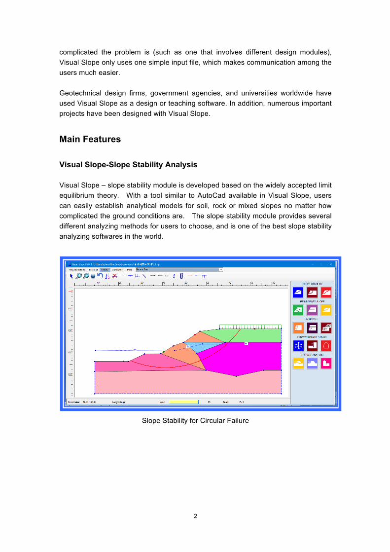
Main Features Visual Slope-Slope Stability Analysis Visual Slope – slope stability module is developed based on the widely accepted limit equilibrium theory. With a tool similar to AutoCad available in Visual Slope, users can easily establish analytical models for soil, rock or mixed slopes no matter how complicated the ground conditions are. The slope stability module provides several different analyzing methods for users to choose, and is one of the best slope stability analyzing softwares in the world.
Slope Stability for Circular Failure

3
Slope Stability Analysis along Rock Joints
Slope Stability Random Search along Rock Fractures

4
Slope Stability Analysis under Seepage Pressure
Slope Stability Analysis after Rainfall Main Features of Slope Stability Analysis
Ø Bishop circular failure surface method for soil slopes Ø Janbu translational or irregular failure surface method for rock slopes Ø Spencer method for both soil and rock slopes Ø Morgenstern method for both soil and rock slopes Ø Transfer coefficient method for rock slopes Ø Seismic, groundwater, water head, porepressure, and seepage pressure
conditions, as well as strength reduction along failure surfaces considered in slope stability analysis
5
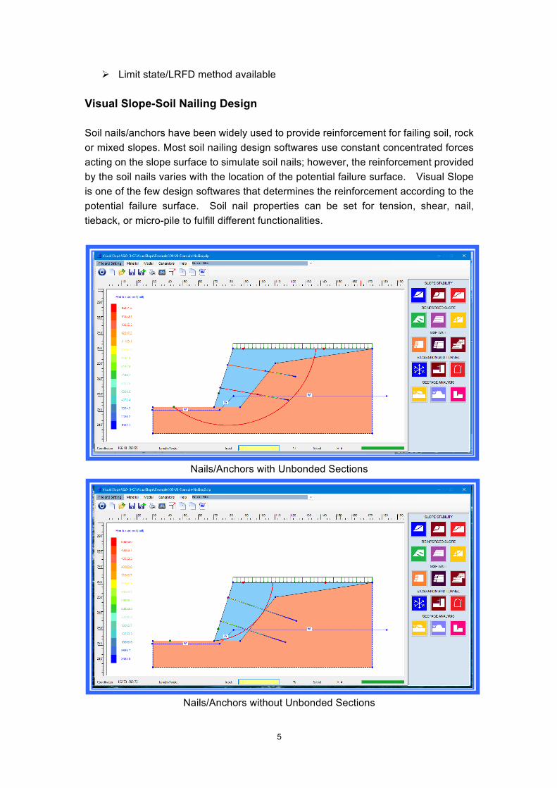
Ø Limit state/LRFD method available Visual Slope-Soil Nailing Design Soil nails/anchors have been widely used to provide reinforcement for failing soil, rock or mixed slopes. Most soil nailing design softwares use constant concentrated forces acting on the slope surface to simulate soil nails; however, the reinforcement provided by the soil nails varies with the location of the potential failure surface. Visual Slope is one of the few design softwares that determines the reinforcement according to the potential failure surface. Soil nail properties can be set for tension, shear, nail, tieback, or micro-pile to fulfill different functionalities.
Nails/Anchors with Unbonded Sections
Nails/Anchors without Unbonded Sections
6
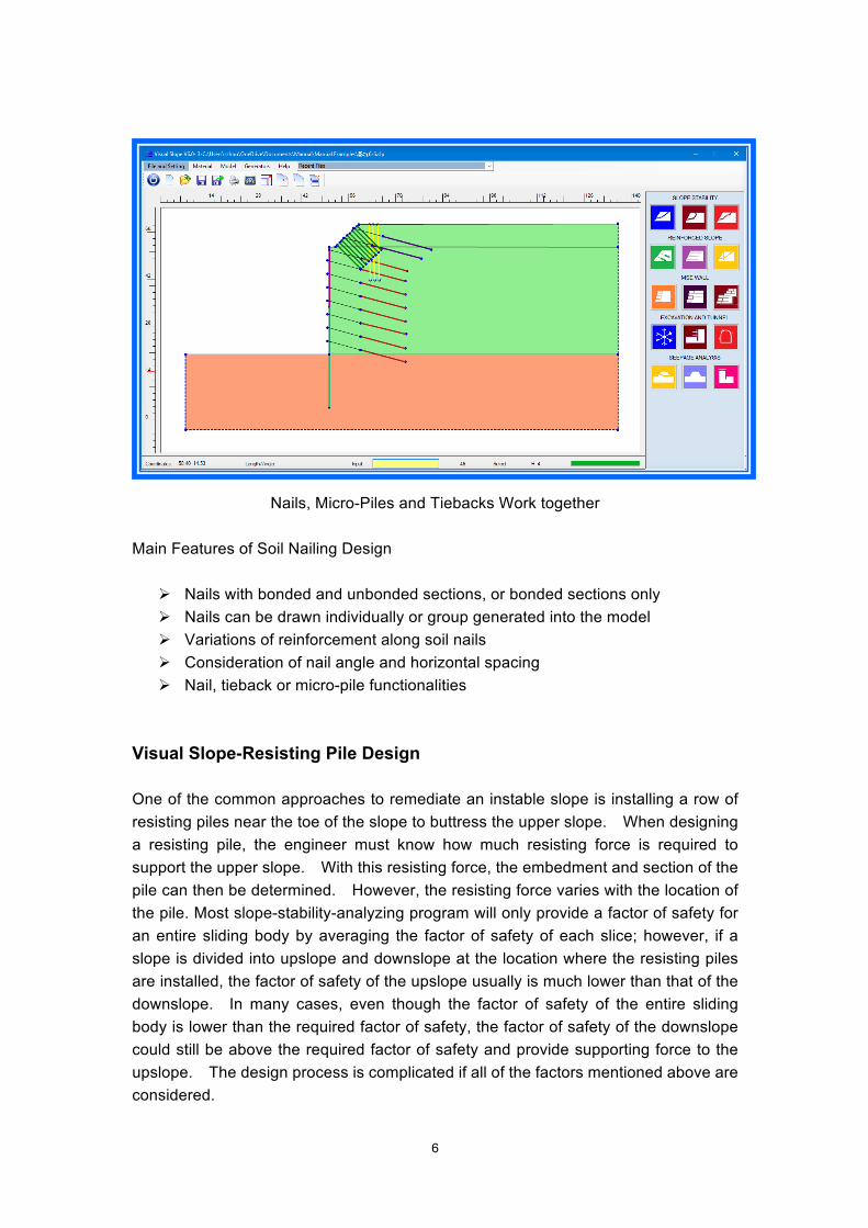
Nails, Micro-Piles and Tiebacks Work together
Main Features of Soil Nailing Design
Ø Nails with bonded and unbonded sections, or bonded sections only Ø Nails can be drawn individually or group generated into the model Ø Variations of reinforcement along soil nails Ø Consideration of nail angle and horizontal spacing Ø Nail, tieback or micro-pile functionalities
Visual Slope-Resisting Pile Design One of the common approaches to remediate an instable slope is installing a row of resisting piles near the toe of the slope to buttress the upper slope. When designing a resisting pile, the engineer must know how much resisting force is required to support the upper slope. With this resisting force, the embedment and section of the pile can then be determined. However, the resisting force varies with the location of the pile. Most slope-stability-analyzing program will only provide a factor of safety for an entire sliding body by averaging the factor of safety of each slice; however, if a slope is divided into upslope and downslope at the location where the resisting piles are installed, the factor of safety of the upslope usually is much lower than that of the downslope. In many cases, even though the factor of safety of the entire sliding body is lower than the required factor of safety, the factor of safety of the downslope could still be above the required factor of safety and provide supporting force to the upslope. The design process is complicated if all of the factors mentioned above are considered.
7
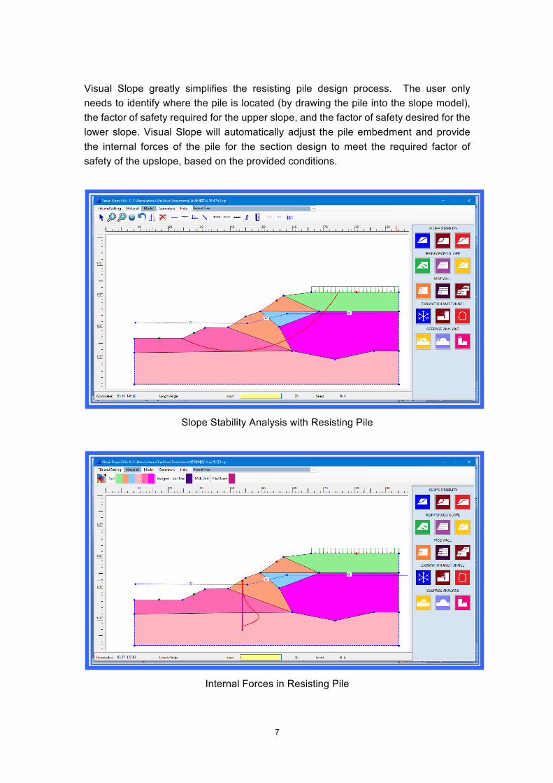
Visual Slope greatly simplifies the resisting pile design process. The user only needs to identify where the pile is located (by drawing the pile into the slope model), the factor of safety required for the upper slope, and the factor of safety desired for the lower slope. Visual Slope will automatically adjust the pile embedment and provide the internal forces of the pile for the section design to meet the required factor of safety of the upslope, based on the provided conditions.
Slope Stability Analysis with Resisting Pile
Internal Forces in Resisting Pile

8
Resisting Pile with Tieback
Features of Resisting Pile Design
Ø Clear and simple Ø Automatic search of most critical failure surface Ø Automatic adjustment of embedment of resisting pile Ø Consideration of downslope supporting fact Ø Resisting pile with tiebacks Ø Internal forces calculation for section design
Visual Slope-MSE Wall Design Mechanical Stabilized Earth (MSE) Walls are widely used as retaining systems for roadway, commercial or residential projects. MSE wall design consists of: 1) Global stability analysis 2) Compound stability analysis 3) External stability analyses that include sliding analysis, overturning analysis and bearing capacity analysis 4) Internal stability analyses that include pullout analysis, overstress analysis, sliding over reinforcement, connection strength analysis and block toppling analysis 5) Settlement analysis Visual Slope is the only software on the market that can perform all these analyses together within one program. Visual Slope is also suitable for tiered MSE walls. The program will automatically count the load from the upper tier walls when analyzing the lower tier wall.
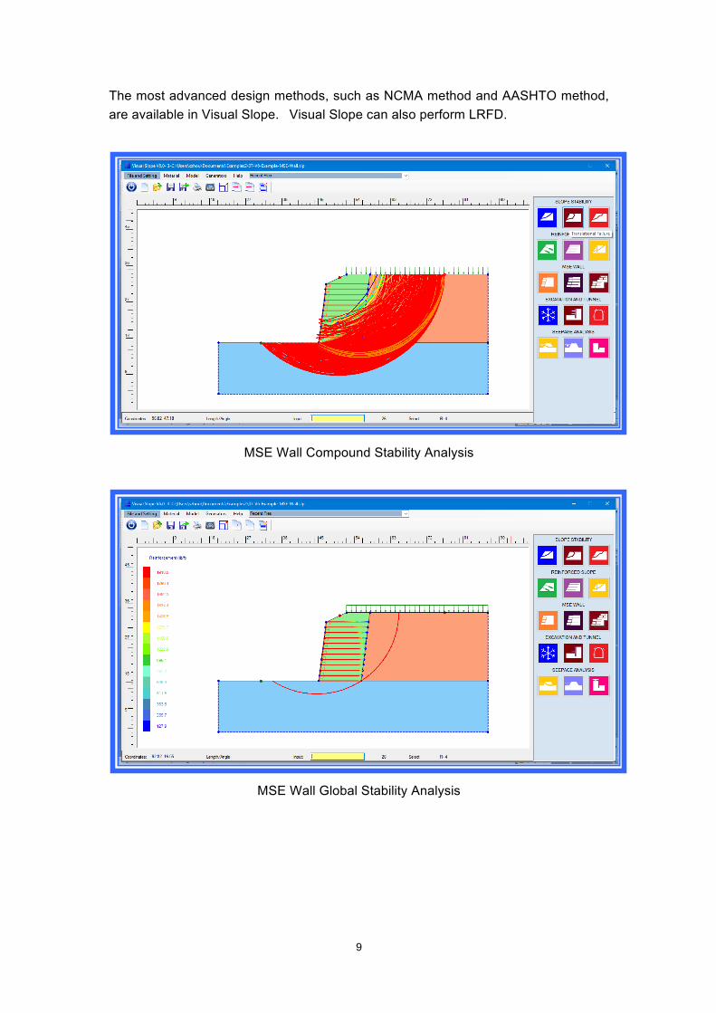
9
The most advanced design methods, such as NCMA method and AASHTO method, are available in Visual Slope. Visual Slope can also perform LRFD.
MSE Wall Compound Stability Analysis
MSE Wall Global Stability Analysis

10
MSE Wall Internal and External Stability Analyses
Tiered MSE Wall Design
Features of MSE Wall Design Module
Ø Single and tiered MSE wall generator Ø Equipped with most advanced design methods Ø Rich database geo-synthetic and wall block

11
Ø Detailed report
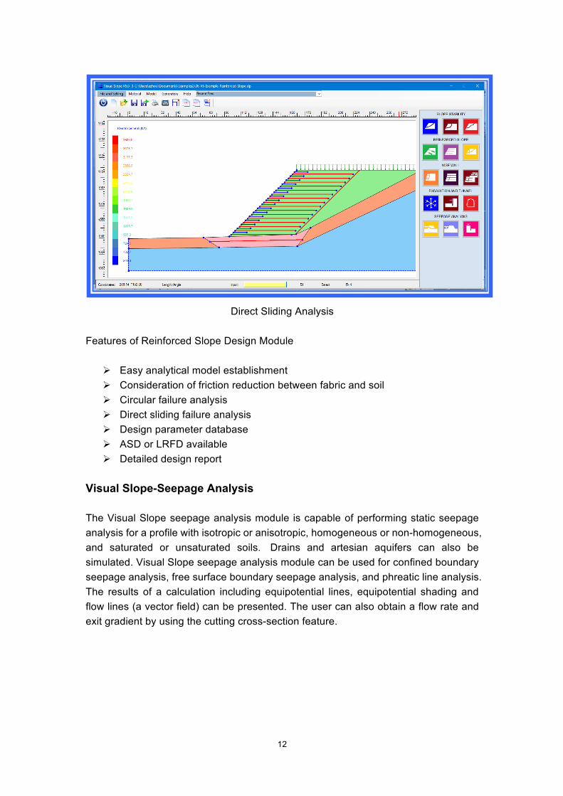
Visual Slope-Reinforced Slope Design In reinforced slope design, most computer softwares only provide a circular failure analyzing method. Using this method, a very important failure mechanism – soil body directly sliding over geo-synthetic layers, which in many cases controls the design–is ignored. Visual Slope is one of the few softwares that can provide both circular failure and directly sliding failure analyzing methods. Visual Slope provides clear results for factor of safety, capacity of reinforcement of each layer, and the failure mechanism. In design, users can use geo-synthetics, metal strips or other materials for reinforcement. The design parameters for the most commonly used materials have been stored in the Visual Slope database and can be easily used in design. Surcharge, ground water conditions, and seismic effect can also be considered in design. Both allowable strength design (ASD) and load resistance factor design (LRFD) are available.
Circular Failure Analysis
12
Direct Sliding Analysis
Features of Reinforced Slope Design Module
Ø Easy analytical model establishment Ø Consideration of friction reduction between fabric and soil Ø Circular failure analysis Ø Direct sliding failure analysis Ø Design parameter database Ø ASD or LRFD available Ø Detailed design report
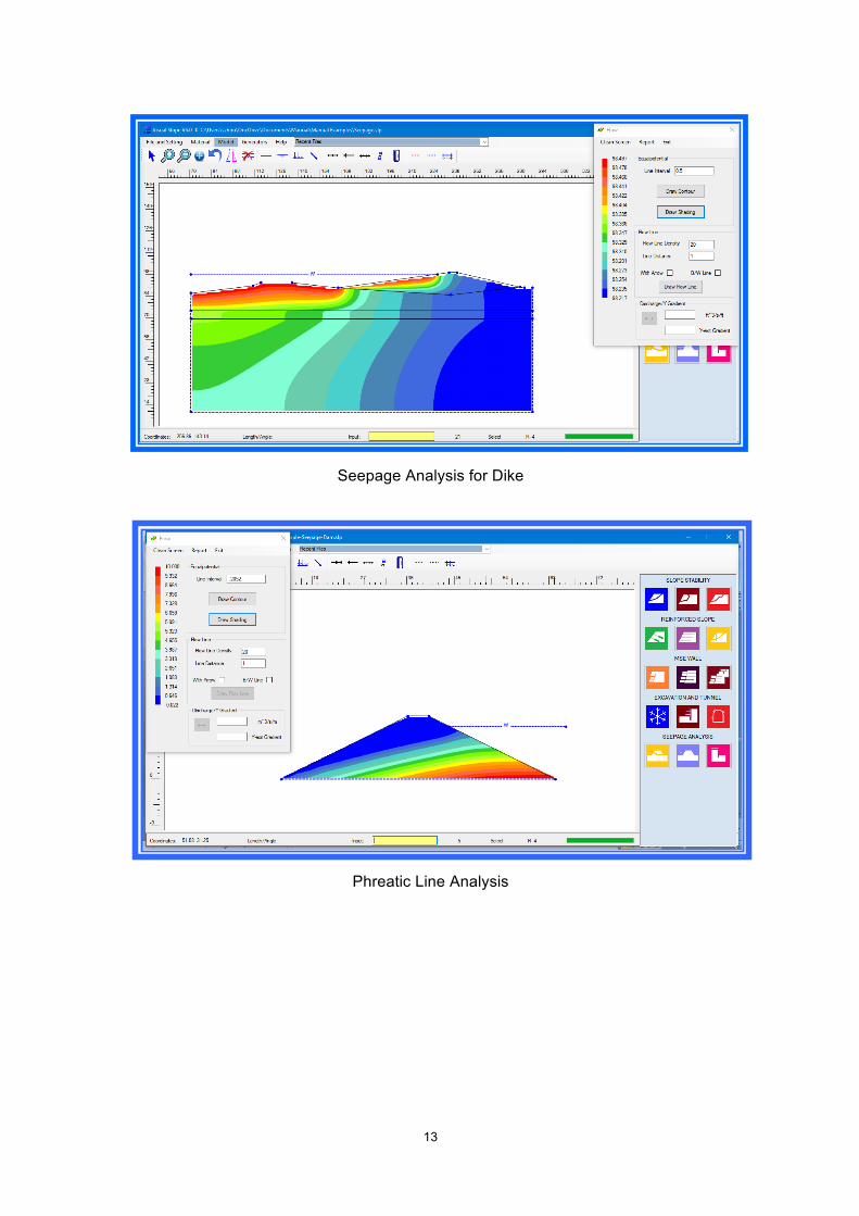
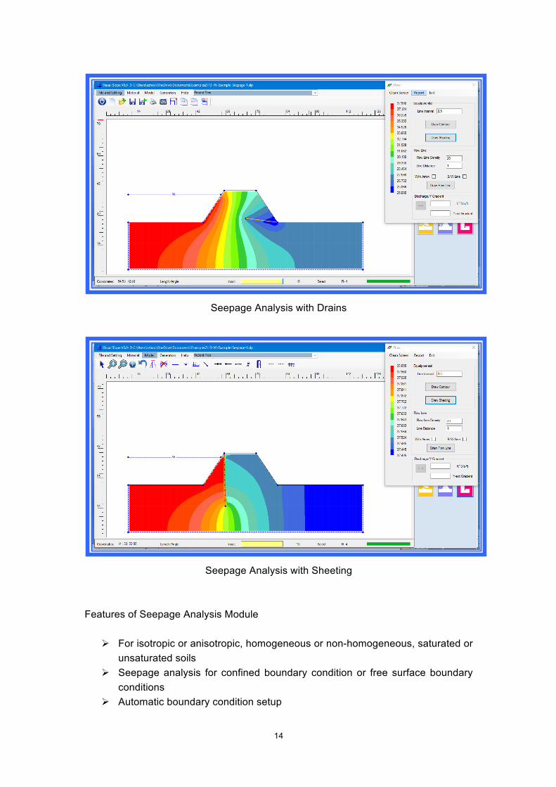
Visual Slope-Seepage Analysis The Visual Slope seepage analysis module is capable of performing static seepage analysis for a profile with isotropic or anisotropic, homogeneous or non-homogeneous, and saturated or unsaturated soils. Drains and artesian aquifers can also be simulated. Visual Slope seepage analysis module can be used for confined boundary seepage analysis, free surface boundary seepage analysis, and phreatic line analysis. The results of a calculation including equipotential lines, equipotential shading and flow lines (a vector field) can be presented. The user can also obtain a flow rate and exit gradient by using the cutting cross-section feature.
13
Seepage Analysis for Dike
Phreatic Line Analysis
14
Seepage Analysis with Drains
Seepage Analysis with Sheeting
Features of Seepage Analysis Module
Ø For isotropic or anisotropic, homogeneous or non-homogeneous, saturated or unsaturated soils
Ø Seepage analysis for confined boundary condition or free surface boundary conditions
Ø Automatic boundary condition setup
15
Ø Phreatic line analysis and flow net analysis Ø Discharge volume and exit gradient calculations Ø Sheeting and drains Ø Artesian aquifers
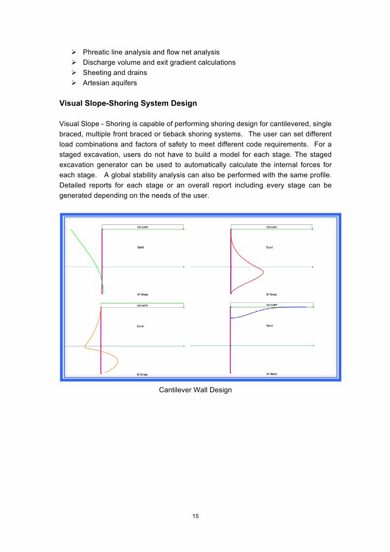
Visual Slope-Shoring System Design Visual Slope - Shoring is capable of performing shoring design for cantilevered, single braced, multiple front braced or tieback shoring systems. The user can set different load combinations and factors of safety to meet different code requirements. For a staged excavation, users do not have to build a model for each stage. The staged excavation generator can be used to automatically calculate the internal forces for each stage. A global stability analysis can also be performed with the same profile. Detailed reports for each stage or an overall report including every stage can be generated depending on the needs of the user.
Cantilever Wall Design
16
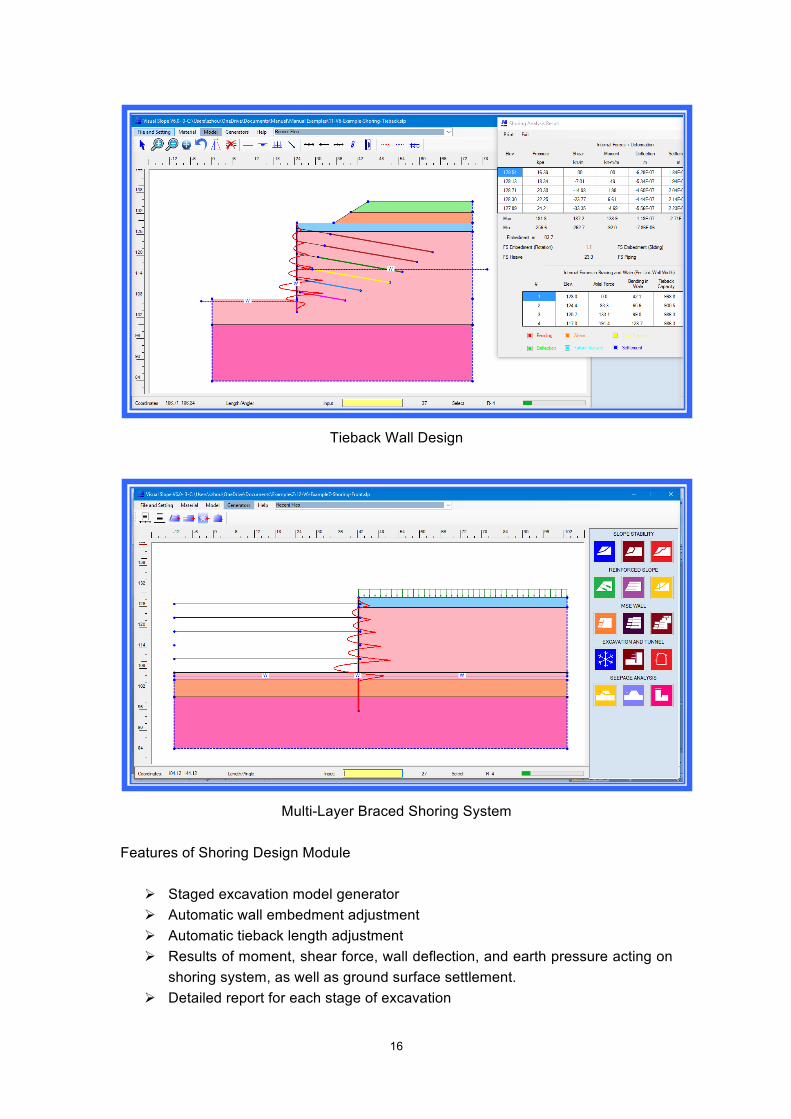
Tieback Wall Design
Multi-Layer Braced Shoring System
Features of Shoring Design Module
Ø Staged excavation model generator Ø Automatic wall embedment adjustment Ø Automatic tieback length adjustment Ø Results of moment, shear force, wall deflection, and earth pressure acting on
shoring system, as well as ground surface settlement. Ø Detailed report for each stage of excavation
17
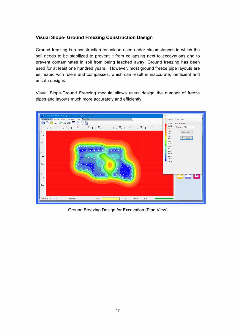
Visual Slope- Ground Freezing Construction Design Ground freezing is a construction technique used under circumstances in which the soil needs to be stabilized to prevent it from collapsing next to excavations and to prevent contaminates in soil from being leached away. Ground freezing has been used for at least one hundred years. However, most ground freeze pipe layouts are estimated with rulers and compasses, which can result in inaccurate, inefficient and unsafe designs. Visual Slope-Ground Freezing module allows users design the number of freeze pipes and layouts much more accurately and efficiently.
Ground Freezing Design for Excavation (Plan View)
18
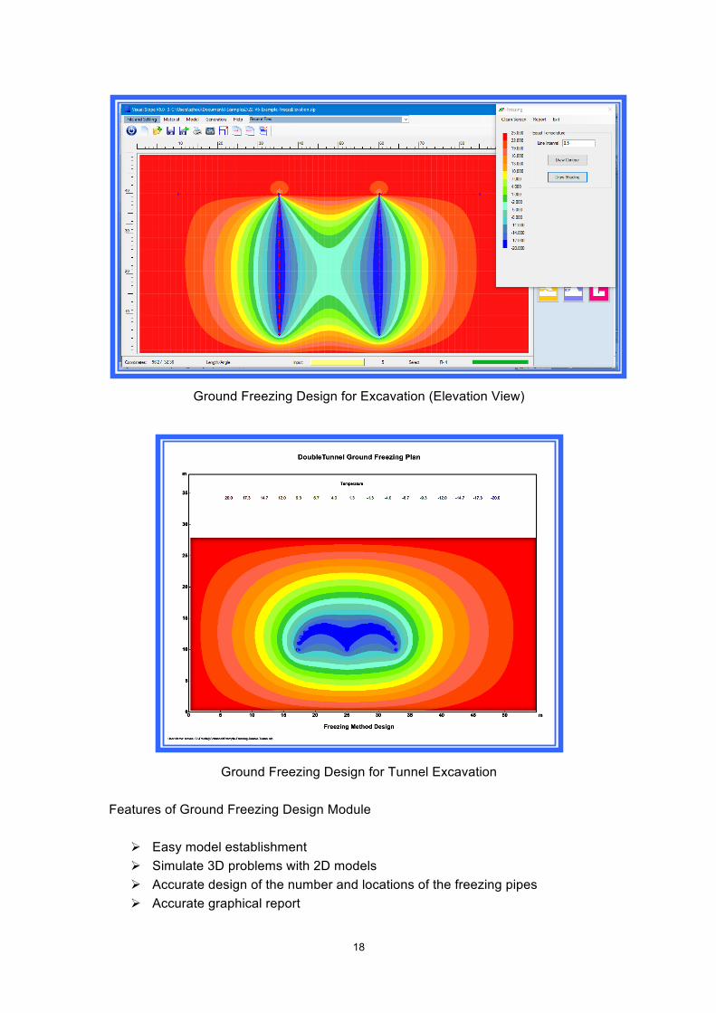
Ground Freezing Design for Excavation (Elevation View)
Ground Freezing Design for Tunnel Excavation
Features of Ground Freezing Design Module
Ø Easy model establishment Ø Simulate 3D problems with 2D models Ø Accurate design of the number and locations of the freezing pipes Ø Accurate graphical report

19
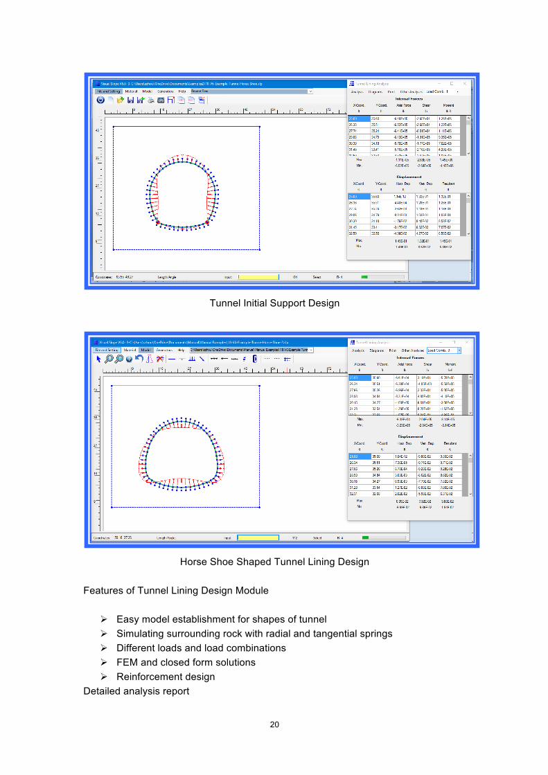
Visual Slope- Tunnel Lining Design There are many computer programs for tunnel lining design. However, only a few are able to provide results that can be used directly for tunnel design because project specified load factors and load combinations cannot be included in the calculations with most design programs. Although some programs are able to account for the load factors and load combinations, they may require extensive amounts of time to set up the computer models for calculation. Visual Slope-Tunnel Design module uses a beam-spring model that can include specified load factors and load combinations for initial steel set design and final lining design. The interaction between the tunnel structure and the surrounding soil/rock is simulated with radial and tangential springs. Users can use the tunnel generator to set up calculation models with different shapes in just a few minutes. All load combinations can be calculated with just one click.
Circular Tunnel Lining Design
20
Tunnel Initial Support Design
Horse Shoe Shaped Tunnel Lining Design
Features of Tunnel Lining Design Module
Ø Easy model establishment for shapes of tunnel Ø Simulating surrounding rock with radial and tangential springs Ø Different loads and load combinations Ø FEM and closed form solutions Ø Reinforcement design
Detailed analysis report