reading: chapter 3
TRANSCRIPT

1/30/14 1
Switching and Forwarding Reading: Chapter 3

1/30/14 2
Switching and Forwarding Next Problem:
Enable communication between hosts that are not directly connected…Fundamental Problem of the Internet or any large Network
Outline/Goals Store-and-Forward Switches Bridges and Extended LANs Cell Switching Segmentation and Reassembly Spanning Tree Cut-through

1/30/14 3
Shuttling Data at Different Layers • Different devices switch different things
– Physical layer: electrical signals (repeaters and hubs) – Link layer: frames (bridges and switches) – Network layer: packets (routers) – TCP/IP
Application gateway!
Transport gateway!
Router!
Bridge, switch!
Repeater, hub!
Frameheader!
IPheader!
TCPheader!
User!data!
1/30/14 4
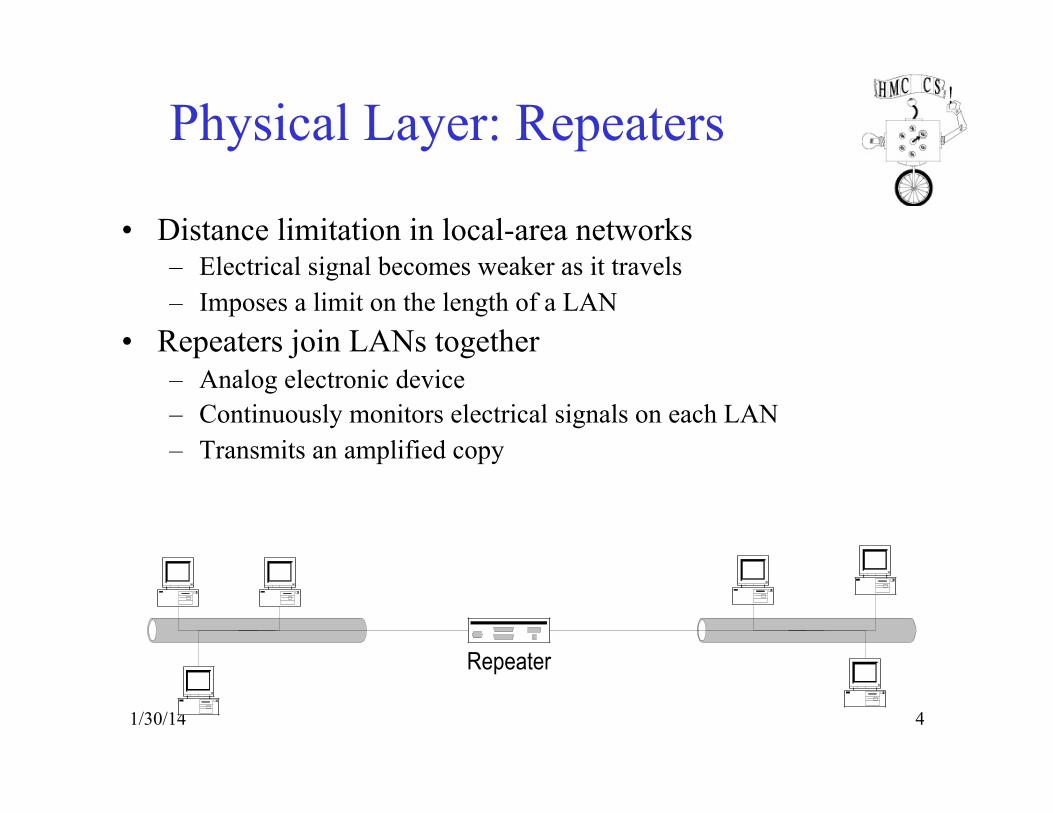
Physical Layer: Repeaters
• Distance limitation in local-area networks – Electrical signal becomes weaker as it travels – Imposes a limit on the length of a LAN
• Repeaters join LANs together – Analog electronic device – Continuously monitors electrical signals on each LAN – Transmits an amplified copy
Repeater
5
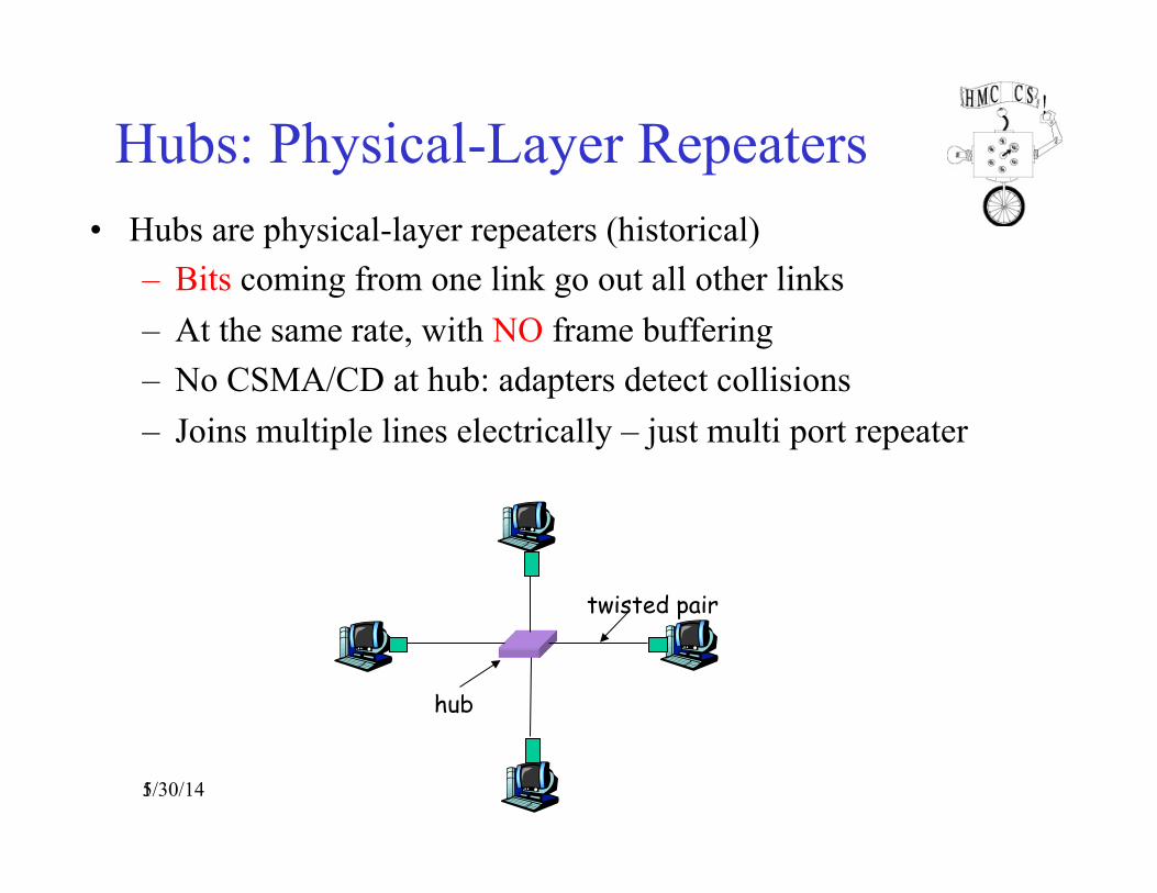
Hubs: Physical-Layer Repeaters • Hubs are physical-layer repeaters (historical)
– Bits coming from one link go out all other links – At the same rate, with NO frame buffering – No CSMA/CD at hub: adapters detect collisions – Joins multiple lines electrically – just multi port repeater
twisted pair
hub
1/30/14
6
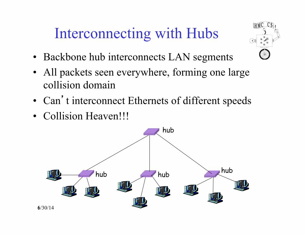
Interconnecting with Hubs • Backbone hub interconnects LAN segments • All packets seen everywhere, forming one large
collision domain • Can’t interconnect Ethernets of different speeds • Collision Heaven!!!
hub hub hub
hub
1/30/14

1/30/14 7
Limitations of Repeaters and Hubs • One large collision domain
– Every bit is sent everywhere – So, aggregate throughput is limited – E.g., three departments each get 10 Mbps independently – … and then connect via a hub and must share 10 Mbps
• Cannot support multiple LAN technologies – Does not buffer or interpret frames – So, can’t interconnect between different rates or formats – E.g., 10 Mbps Ethernet and 100 Mbps Ethernet
• Limitations on maximum nodes and distances – Does not circumvent the limitations of shared media – E.g., still cannot go beyond 2500 meters on Ethernet

1/30/14 8
Link Layer: Scalable Networks • Switch/Bridge
– Forwards frames from input port to output port – stores frames, needs memory
– port selected based on address in frame header
• Advantages – cover large geographic area (tolerate latency) – support large numbers of hosts (scalable bandwidth) – can add hosts without performance penalty vs. shared medium
Inputports
T3T3
STS-1
T3T3STS-1
Switch
Outputports
9
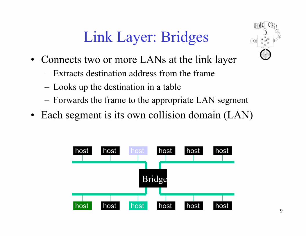
Link Layer: Bridges • Connects two or more LANs at the link layer
– Extracts destination address from the frame – Looks up the destination in a table – Forwards the frame to the appropriate LAN segment
• Each segment is its own collision domain (LAN)
host host host host host
host host host host host
host
host
Bridge
1/30/14 10
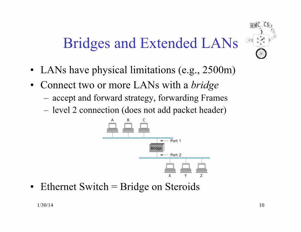
Bridges and Extended LANs
• LANs have physical limitations (e.g., 2500m) • Connect two or more LANs with a bridge
– accept and forward strategy, forwarding Frames – level 2 connection (does not add packet header)
• Ethernet Switch = Bridge on Steroids
A
Bridge
B C
X Y Z
Port 1
Port 2

1/30/14 11
Learning Bridges • Do not forward when unnecessary • Maintain forwarding table
Host Port A 1 B 1 C 1 X 2 Y 2 Z 2
• Learn table entries based on source address of frame • Table is an optimization; need not be complete • Always forward broadcast frames • Timeouts & Aging - Why?
A
Bridge
B C
X Y Z
Port 1
Port 2
12
Link Layer: Switches • Link layer device
– Stores and forwards (Ethernet) frames – Examines frame header and selectively forwards
frame based on MAC dest address – When frame is to be forwarded on segment, uses
CSMA/CD to access segment • Transparent
– Hosts are unaware of presence of switches • Plug-and-play, self-learning
– Switches do not need to be configured 1/30/14

13
Link Layer: Switches • Typically connect individual computers
– A switch is essentially same as a bridge – … though typically used to connect hosts, not LANs – Collision domain moved into switch
• Like bridges, support concurrent communication – Host A can talk to C, while B talks to D – Many ports, many simultaneous conversations
switch
A
B
C
D1/30/14

Spring 2002 14
Switching Hardware
• Design Goals – throughput (depends on traffic model) – scalability (a function of n)
• Ports – circuit management (e.g., map VCIs, route datagrams) – buffering (input and/or output)
• Fabric – as simple as possible – sometimes do buffering (internal)
Switch fabric
Control processor
Output port Input
port
Spring 2002 15
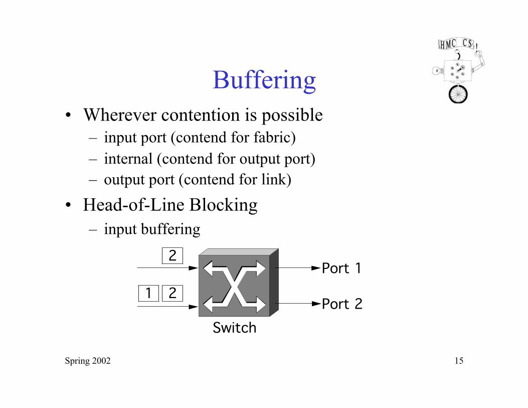
Buffering • Wherever contention is possible
– input port (contend for fabric) – internal (contend for output port) – output port (contend for link)
• Head-of-Line Blocking – input buffering
Switch
2
21Port 1
Port 2

Spring 2002 16
Crossbar Switches

Spring 2002 17
Workstation-Based or Switch Switching
• Aggregate bandwidth – 1/2 of the I/O bus bandwidth – capacity shared among all hosts connected to switch – example: 1Gbps bus can support 5 x 100Mbps ports (in theory)
• Packets-per-second – must be able to switch
small packets – 300,000 packets-per-
second is achievable – e.g., 64-byte packets
implies 155Mbps
I/O bus
Interface 1
Interface 2
Interface 3
CPU
Main memory
Switching Fabric
1/30/14 18
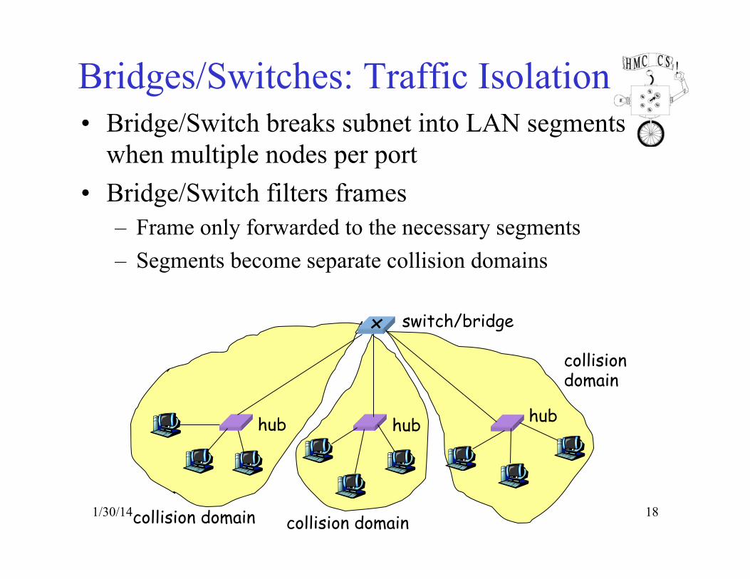
Bridges/Switches: Traffic Isolation • Bridge/Switch breaks subnet into LAN segments
when multiple nodes per port • Bridge/Switch filters frames
– Frame only forwarded to the necessary segments – Segments become separate collision domains
hub hub hub
switch/bridge
collision domain collision domain
collision domain

1/30/14 19
Bridge/Switch Advantages Over Hub/Repeater
• Only forwards frames as needed – Filters frames to avoid unnecessary load on segments – Sends frames only to segments that need to see them
• Extends the geographic span of the network – Separate collision domains allow longer distances, less collisions
• Improves privacy by limiting scope of frames – Hosts can ONLY “snoop” the traffic traversing their segment – … but not all the rest of the traffic
• Applies carrier sense and collision detection – Does not transmit when the link is busy – Applies exponential back-off after a collision
• Can join segments using different technologies

20
Bridge/Switch Advantages over Hubs/Repeater
• Dedicated access – Host has direct connection to the switch – … rather than a shared LAN connection
• Full duplex – Each connection can send in both directions – Host sending to switch, and host receiving from switch – E.g., in 10BaseT and 100BaseT
• Completely avoids collisions – Each connection is a bidirectional point-to-point link – No need for carrier sense, collision detection, and so on
1/30/14
1/30/14 21
Bridge/Switch Disadvantages Over Hubs/Repeater
• Delay in forwarding frames – Bridge/switch must receive and parse the frame – … and perform a look-up to decide where to forward – Storing and forwarding the packet introduces delay – Solution: cut-through switching ???
• Need to learn where to forward frames – Bridge/switch needs to construct a forwarding table – Ideally, without intervention from network administrators – Solution: self-learning
• Higher cost – More complicated devices that cost more money – But hardware is free
1/30/14 22
Bridge/Switch operation: Broadcast and Multicast
• Forward (flood) all broadcast/multicast frames – current practice
• Learn when no group members downstream • Accomplished by having each member of group G
send a frame to bridge multicast address with G in source field
• Must maintain many Multicast graphs

23
Bridge/Switch: Flooding Can Lead to Loops
• Switches sometimes need to broadcast frames – Upon receiving a frame with an unfamiliar destination – Upon receiving a frame sent to the broadcast address
• Broadcasting is implemented by flooding – Transmitting frame out every interface – … except the one where the frame arrived
• Flooding can lead to forwarding loops – E.g., if the network contains a cycle of switches – Either accidentally, or by design for higher reliability
1/30/14

1/30/14 24
Bridge/Switch: Loop Solution Spanning Tree Algorithm
• Problem: loops
• Bridges run a distributed spanning tree algorithm – select which bridges actively forward – developed by Radia Perlman – now IEEE 802.1 specification – Subgraph covers all LANs, no loops
A
C
E
D
B
K
F
H
J
G
I
B3
B7
B4
B2
B5
B1
B6
(a) (b)
1/30/14 25
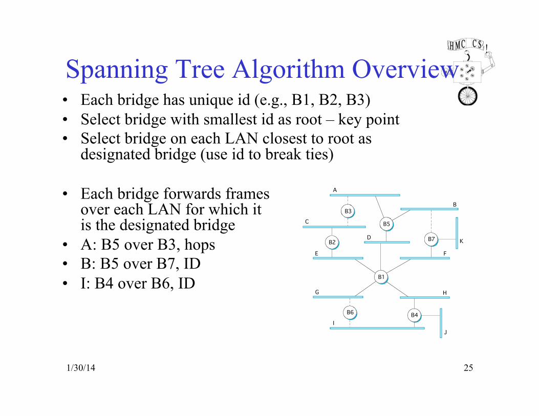
Spanning Tree Algorithm Overview • Each bridge has unique id (e.g., B1, B2, B3) • Select bridge with smallest id as root – key point • Select bridge on each LAN closest to root as
designated bridge (use id to break ties)
• Each bridge forwards frames over each LAN for which it is the designated bridge
• A: B5 over B3, hops • B: B5 over B7, ID • I: B4 over B6, ID
A
C
E
D
B
K
F
H
J
G
I
B5
B2
B3
B7
B4
B1
B6
1/30/14 26
Spanning Tree Algorithm Details • Bridges exchange configuration messages
– id for bridge sending the message – id for what the sending bridge believes to be root bridge – distance (hops) from sending bridge to root bridge
• Each bridge records current best configuration message for each port
• Initially, each bridge believes it is the root – sends out config info

1/30/14 27
Spanning Tree Algorithm Details (cont)
• When learn not root, stop generating config messages – in steady state, only root generates configuration messages
• When learn not designated bridge, stop forwarding config messages – in steady state, only designated bridges forward config messages
• Root continues to periodically send config messages • If any bridge does not receive config message after a period
of time, it starts generating config messages claiming to be the root
1/30/14 28
Limitations of Bridges/Switches • Do not scale
– spanning tree algorithm does not scale – broadcast does not scale
• Do not accommodate heterogeneity
• Not really directly connected: – Drops, reorders, no guaranteed delivery
29
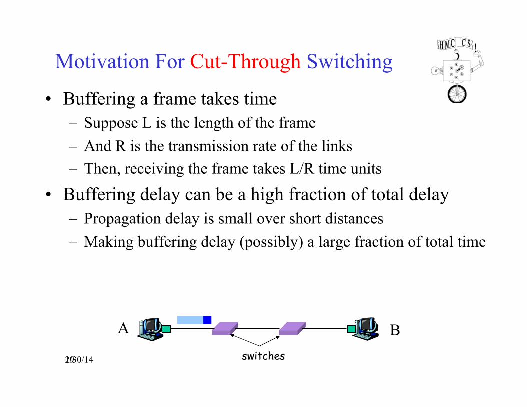
Motivation For Cut-Through Switching
• Buffering a frame takes time – Suppose L is the length of the frame – And R is the transmission rate of the links – Then, receiving the frame takes L/R time units
• Buffering delay can be a high fraction of total delay – Propagation delay is small over short distances – Making buffering delay (possibly) a large fraction of total time
A Bswitches 1/30/14
30
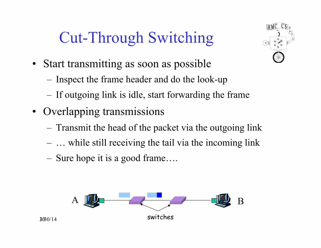
Cut-Through Switching • Start transmitting as soon as possible
– Inspect the frame header and do the look-up – If outgoing link is idle, start forwarding the frame
• Overlapping transmissions – Transmit the head of the packet via the outgoing link – … while still receiving the tail via the incoming link – Sure hope it is a good frame….
A Bswitches 1/30/14
1/30/14 31
Frame Routing Knowing and Traveling the Path
• Problem: Choose output port – Source Routing – Virtual Circuits – Datagrams
• Problem: Name receiving host: – Addresses

1/30/14 32
Approach 1: Source Routing
0
132
01 3
2
013
2
013
23 0 1 3 01
30 1
Switch 3
Host B
Switch 2
Host A
Switch 1
Need to know: Path to Destination Ports on Path to Destination Header size is variable Header rotation – checksum issues
1/30/14 33
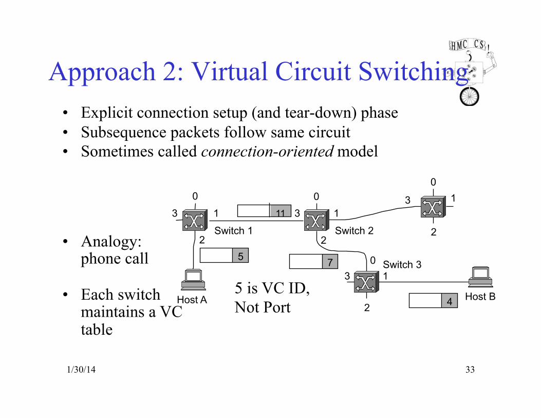
Approach 2: Virtual Circuit Switching • Explicit connection setup (and tear-down) phase • Subsequence packets follow same circuit • Sometimes called connection-oriented model
• Analogy: phone call
• Each switch maintains a VC table
2
0 1
2 3
0 1
2
3
0 1 3
0 1
2
3
Host A Host B
Switch 3
Switch 2 Switch 1
7 5
4
11
5 is VC ID, Not Port

1/30/14 34
Notes: Virtual Circuit Model • Typically wait full RTT for connection setup before
sending first data packet.
• While the connection request contains the full address for destination, each data packet contains only a small identifier, making the per-packet header overhead small.
• If a switch or a link in a connection fails, the connection is broken and a new one needs to be established.
• Connection setup provides an opportunity to reserve resources.
1/30/14 35
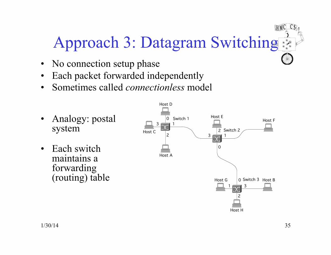
Approach 3: Datagram Switching • No connection setup phase • Each packet forwarded independently • Sometimes called connectionless model
• Analogy: postal system
• Each switch maintains a forwarding (routing) table
0
132
01 3
2
013
2
Switch 3 Host B
Switch 2
Host A
Switch 1
Host C
Host D
Host EHost F
Host G
Host H

1/30/14 36
Notes: Datagram Model • There is no round trip delay waiting for connection setup;
a host can send data as soon as it is ready.
• Source host has no way of knowing if the network is capable of delivering a packet or if the destination host is even up.
• Since packets are treated independently, it is possible to route around link and node failures.
• Since every packet must carry the full address of the destination, the overhead per packet is higher than for the connection-oriented model.
• Someone must build the tables in each switch…

1/30/14 37
Example Tables
• Circuit Table (switch 1, port 2)
• Forwarding Table (switch 1)
Address PortA 2C 3F 1G 1… …
VC In VC Out Port Out
5 11 16 8 1
… … …
Typical Network • Individual broadcast and collision domains • Connected by routers • Routers add latency to packet transmission
1/30/14 38
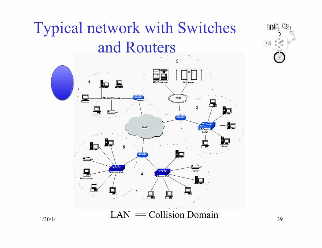
Typical network with Switches and Routers
1/30/14 39 LAN == Collision Domain
1/30/14 40
Evolution Toward Virtual LANs • In the olden days…
– Thick cables snaked through cable ducts in buildings – Every computer they passed was plugged in – All people in adjacent offices were put on the same LAN – Independent of whether they belonged together or not
• More recently… – Hubs and switches changed all that – Every office connected to central wiring closets – Often multiple LANs (k hubs) connected by switches – Want flexibility in mapping offices to different LANs – Routers add some delay
VLAN allows Grouping users based on organizational structure, rather than the physical
layout of the building.!
1/30/14 41
Why Organize LAN by Organizational Structure?
• Security – Ethernet is a shared media – Any interface card can be put into “promiscuous” mode – … and get a copy of all of the traffic (e.g., midterm exam) – So, isolating traffic on separate LANs improves security
• Load – Some LAN segments are more heavily used than others – E.g., researchers running experiments get out of hand – … can saturate their own segment and not the others – Plus, there may be natural locality of communication – E.g., traffic between people in the same research group – Reduce router traffic by keeping on common collision domain
1/30/14 42
LAN Reality: People Move, and Roles Change • Organizational changes are frequent
– E.g., faculty office becomes a grad-student office • Physical rewiring is a major pain
– Requires unplugging the cable from one port – … and plugging it into another – … and hoping you don’t make a mistake
• Would like to “rewire” the building in software – The resulting concept is a Virtual LAN (VLAN)
• VLAN – Virtual LAN – Group devices on different physical LANs as if on same
physical LAN – Shared Collision Domain

VLAN Grouping
1/30/14 43
1/30/14 44
Making VLANs Work • Bridges/switches need configuration tables
– Saying which VLANs are accessible via which interfaces
• Changing the Ethernet header – Adding a field for a VLAN tag – Implemented on the bridges/switches – key point – … but can still interoperate with old Ethernet cards – Devices (nodes) do not care, only switches need to
understand.
VLAN Benefits • Increased performance
– Organized collision domains – workgroups with different private services
– Group users into logical networks with smaller collision and broadcast domains –
– Reduce routed traffic • Improved manageability
– Allow centralized configuration of devices located in diverse locations
– Easier to add/subtract nonlocal users – Configure LANs without moving hosts
1/30/14 45
VLAN Benefits • Network Tuning
– Group users and software configurations – IP addresses, subnet masks, etc. – Bootp and DHCP easier to manage
• Increased Security
– sensitive material – isolate testing
1/30/14 46

1/30/14 47
Moving From Switches to Routers
• Advantages of switches over routers – Plug-and-play – Fast filtering and forwarding of frames – No pronunciation ambiguity (e.g., “rooter” vs. “rowter”) :-)
• Disadvantages of switches over routers – Topology is restricted to a spanning tree – Large networks require large ARP tables – Broadcast storms can cause the network to collapse

1/30/14 48
Comparing Hubs, Switches, & Routers
hubs routers switches
traffic isolation
no yes yes
plug & play yes no yes
optimal routing
no yes no
cut through
yes no yes
1/30/14 49
Conclusion • Shuttling data from one link to another
– Bits, frames, packets, … – Repeaters/hubs, bridges/switches, routers, …
• Key ideas in switches – Cut-through switching – Self learning of the switch table – Spanning trees – Virtual LANs (VLANs)