reading plan sheets - oregon.gov home page · bubble notes are used in conjunction with the...
TRANSCRIPT
Re
ad
ing
P
lan
Sh
ee
ts
2018 ODOT Inspector’s Manual for Signal Construction 183
ODOT Inspector’s Manual For Signal Construction 2015
183
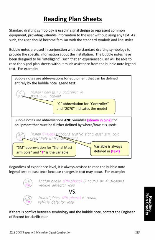
Reading Plan Sheets Standard drafting symbology is used in signal design to represent common equipment, providing valuable information to the user without using any text. As such, the user should become familiar with the standard symbols and line styles. Bubble notes are used in conjunction with the standard drafting symbology to provide the specific information about the installation. The bubble notes have been designed to be “intelligent”, such that an experienced user will be able to read the signal plan sheets without much assistance from the bubble note legend text. For example:
Bubble notes use abbreviations for equipment that can be defined entirely by the bubble note legend text:
Bubble notes use abbreviations AND variables (shown in pink) for equipment that must be further defined by where/how it is used:
Regardless of experience level, it is always advised to read the bubble note legend text at least once because changes in text may occur. For example:
VS.
If there is conflict between symbology and the bubble note, contact the Engineer of Record for clarification.
“C” abbreviation for “Controller” and “2070” indicates the model
Variable is always defined in (text)
“SM” abbreviation for “Signal Mast arm pole” and “T” is the variable
Re
ad
ing
P
lan
Sh
ee
ts
184 2018 ODOT Inspector’s Manual for Signal Construction184 2018 ODOT Inspector’s Manual for Signal Construction
Re
ad
ing
P
lan
Sh
ee
ts
2018 ODOT Inspector’s Manual for Signal Construction 185
ODOT Inspector’s Manual For Signal Construction 2015
185
Re
ad
ing
P
lan
Sh
ee
ts
186 2018 ODOT Inspector’s Manual for Signal Construction186 2018 ODOT Inspector’s Manual for Signal Construction
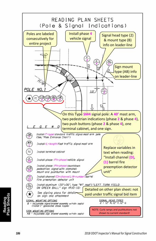
Poles are labeled consecutively for entire project
Signal head type (2) & mount type (B) info on leader‐line
Sign mount type (AB) info on leader‐line
On this Type SM4 signal pole: A 40’ mast arm, two pedestrian indications (phase 2 & phase 4), two push buttons (phase 2 & phase 4), one terminal cabinet, and one sign.
Install phase 4 vehicle signal
Replace variables in text when reading: “Install channel (D), (1) barrel fire preemption detector unit”
Detailed on other plan sheet: not paid under traffic signal bid item
NOTE: Curb ramps and pushbuttons not shown to current standard!
Re
ad
ing
P
lan
Sh
ee
ts
2018 ODOT Inspector’s Manual for Signal Construction 187
ODOT Inspector’s Manual For Signal Construction 2015
187
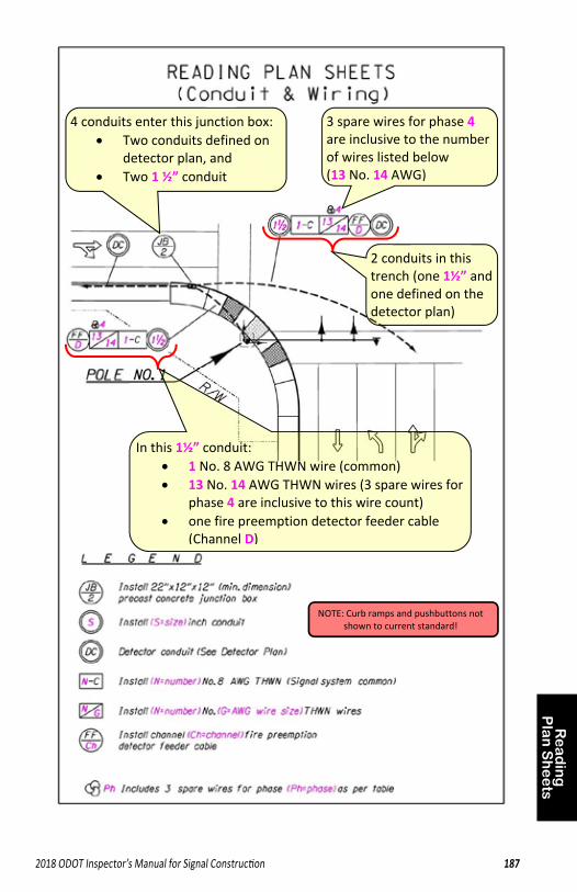
In this 1½” conduit: 1 No. 8 AWG THWN wire (common) 13 No. 14 AWG THWN wires (3 spare wires for
phase 4 are inclusive to this wire count) one fire preemption detector feeder cable
(Channel D)
4 conduits enter this junction box: Two conduits defined on
detector plan, and Two 1 ½” conduit
2 conduits in this trench (one 1½” and one defined on the detector plan)
3 spare wires for phase 4 are inclusive to the number of wires listed below (13 No. 14 AWG)
NOTE: Curb ramps and pushbuttons not shown to current standard!
Re
ad
ing
P
lan
Sh
ee
ts
188 2018 ODOT Inspector’s Manual for Signal Construction188 2018 ODOT Inspector’s Manual for Signal Construction
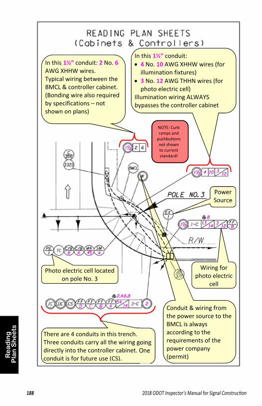
In this 1½” conduit: 2 No. 6 AWG XHHW wires. Typical wiring between the BMCL & controller cabinet. (Bonding wire also required by specifications – not shown on plans)
In this 1½” conduit: 4 No. 10 AWG XHHW wires (for illumination fixtures)
3 No. 12 AWG THHN wires (for photo electric cell)
Illumination wiring ALWAYS bypasses the controller cabinet
Photo electric cell located on pole No. 3
There are 4 conduits in this trench. Three conduits carry all the wiring going directly into the controller cabinet. One conduit is for future use (CS).
Power Source
Conduit & wiring from the power source to the BMCL is always according to the requirements of the power company (permit)
Wiring for photo electric
cell
NOTE: Curb ramps and pushbuttons not shown to current standard!
Re
ad
ing
P
lan
Sh
ee
ts
2018 ODOT Inspector’s Manual for Signal Construction 189
ODOT Inspector’s Manual For Signal Construction 2015
189
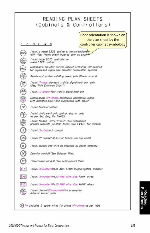
Door orientation is shown on the plan sheet by the
controller cabinet symbology
Re
ad
ing
P
lan
Sh
ee
ts
190 2018 ODOT Inspector’s Manual for Signal Construction190 2018 ODOT Inspector’s Manual for Signal Construction
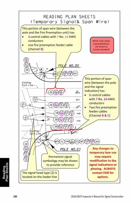
Any changes to temporary lane use
may require modification to the signal indications or phasing. ALWAYS contact EOR for
options. The signal head type (2) is located on the leader‐line
This portion of span wire (between the pole and the signal indication) has: 6 control cables
with 7 No. 14 AWG conductors
Two fire preemption feeder cables (Channel B & C)
This portion of span wire (between the pole and the Fire Preemption unit) has: 3 control cables with 7 No. 14 AWG
conductors one fire preemption feeder cable
(channel B)
Permanent signal symbology may be shown
to provide reference
NOTE: Curb ramps and pushbuttons not shown to
current standard!
Re
ad
ing
P
lan
Sh
ee
ts
2018 ODOT Inspector’s Manual for Signal Construction 191
ODOT Inspector’s Manual For Signal Construction 2015
191
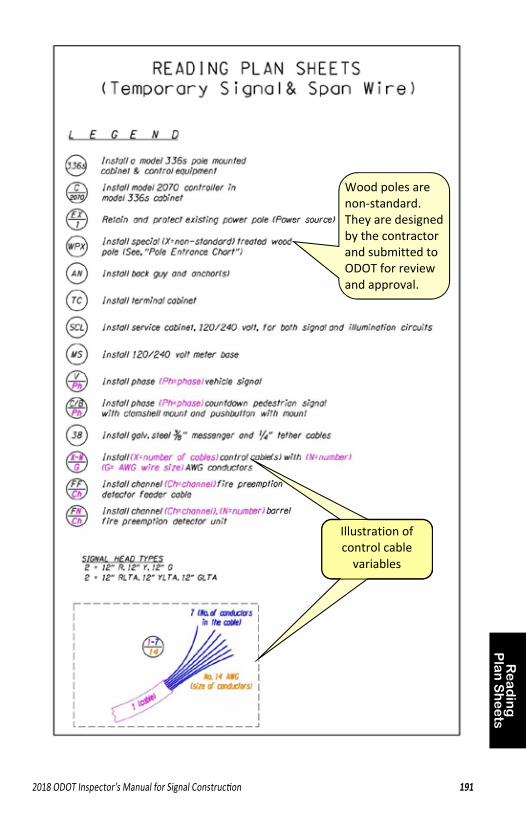
Wood poles are non‐standard. They are designed by the contractor and submitted to ODOT for review and approval.
Illustration of control cable variables
Re
ad
ing
P
lan
Sh
ee
ts
192 2018 ODOT Inspector’s Manual for Signal Construction192 2018 ODOT Inspector’s Manual for Signal Construction
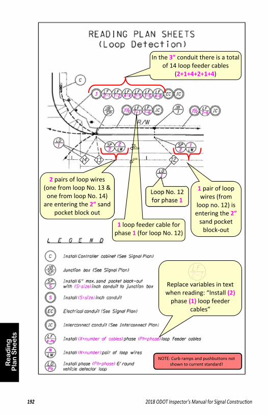
Loop No. 12 for phase 1
2 pairs of loop wires (one from loop No. 13 & one from loop No. 14) are entering the 2” sand
pocket block out
In the 3” conduit there is a total of 14 loop feeder cables
(2+1+4+2+1+4)
1 pair of loop wires (from
loop no. 12) is entering the 2” sand pocket block‐out
1 loop feeder cable for phase 1 (for loop No. 12)
Replace variables in text when reading: “Install (2) phase (1) loop feeder
cables”
NOTE: Curb ramps and pushbuttons not shown to current standard!
Re
ad
ing
P
lan
Sh
ee
ts
2018 ODOT Inspector’s Manual for Signal Construction 193
ODOT Inspector’s Manual For Signal Construction 2015
193
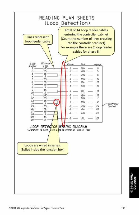
Lines represent loop feeder cable
Loops are wired in series. (Splice inside the junction box)
Total of 14 Loop feeder cables entering the controller cabinet
(Count the number of lines crossing into the controller cabinet).
For example there are 2 loop feeder cables for phase 5.
194 2018 ODOT Inspector’s Manual for Signal Construction194 2018 ODOT Inspector’s Manual for Signal Construction
Website Links
1. Traffic Signal Inspector Certification Information (registration link) http://www.oregon.gov/ODOT/Construction/Pages/Signal-Inspector-Cert.aspx
2. Inspector’s Manual for Signal Construction (updated yearly in January) http://www.oregon.gov/ODOT/Construction/Pages/Signal-Inspector-Cert.aspx
3. Traffic Signal Standards Main Websitehttp://www.oregon.gov/ODOT/Engineering/Pages/Signals.aspx
4. Blue, Green, and Red Sheets (click “product evaluation and approval”) http://www.oregon.gov/ODOT/Engineering/Pages/Signals.aspx
5. Qualified Products List (QPL)http://www.oregon.gov/ODOT/Construction/Pages/Qualified-Products.aspx
6. Non Field‐Tested Materials Acceptance Guide (NTMAG)http://www.oregon.gov/ODOT/Construction/Pages/Structure-Services.aspx
7. Standard Drawings and Baseline Reportshttp://www.oregon.gov/ODOT/Engineering/Pages/Standards.aspx
8. Standard Specifications and Special Provision Boiler Plateshttp://www.oregon.gov/ODOT/Business/Pages/Standard_Specifications.aspx
9. Field Verification Forms (for Signal Pole and Signal Pole Foundation Installation)http://www.oregon.gov/ODOT/Engineering/Pages/Structures.aspx
10. Building Codes Division, Electrical License searchhttp://www.oregon.gov/bcd/licensing/Pages/search.aspx
11. Direct Tension Indicator (DTI) video and March 2016 specification Notes http://www.oregon.gov/ODOT/Construction/Pages/QA.aspx
12. Filenet: archive of all traffic signal plan sheets (click “Drawing Archive”) http://www.oregon.gov/ODOT/Engineering/Pages/Signals.aspx
2018 ODOT Inspector’s Manual for Signal Construction 195
ODOT Inspector’s Manual For Signal Construction 2015
195
INDEX
1
10 foot rule ∙ 92
A
ADA Clear Space ∙ 148 ADA Obstruction ∙ 148 ADA Reach Distance ∙ 98, 148, 150 ADA Turning Space ∙ 148 Adjustable Vehicle Signal Bracket ∙ 49,
130 Agency Electricians ∙ 55, 57, 86, 89, 94,
96, 98, 100, 120, 122, 154, 156, 174, 175
Aluminum Sign Mounting Framework ∙ 24, 130, 136
Anchor Plate ∙ 106 Anchor Rod ∙ 106, 108, 110, 112 Anticipated Items ∙ 84 As‐Constructed Drawings ∙ 175 Audible Pedestrian Signal ∙ 72
B
Backer Rod ∙ 1, 156, 160 Backplates ∙ 25, 152 Battery Back‐up System ∙ 73 Beacon Assemblies ∙ 74 Bike Signals ∙ 181 Blue Sheet Material Info ∙ 3–7 BMC ∙ See Service Cabinet Bonding & Grounding
Bond Wire ∙ 8 Bonded Bushings ∙ 9 Cabinets ∙ 116, 170, 172 Ground Rod & Clamp ∙ 17 Installation ∙ 140 Poles ∙ 108, 112
Bushings ∙ 9, 13
C
Cabinets Controller Cabinet ∙ 58, 172, 180 Reading Plan Sheets ∙ 188, 189 Riser Frames ∙ 41, 172 Service Cabinet ∙ 42, 170 Terminal Cabinet ∙ 45, 116
Cable Ties ∙ 10, 144 Cables ∙ See Wire & Cable Casings ∙ 104, 106, 108 Catalogue Cut Sheets ∙ See Blue or
Green Sheet Material Info Clamshell ∙ See Pedestrian Signal
Mount CLSM ∙ 122 Color Code ∙ 142, 144 Commercial Power Source ∙ See
Electrical Service Communications Bracket ∙ 67 Concrete ∙ 106, 108, 110 Conduit
Bushings ∙ 9, 13 Conduit Body ∙ 14 Conduit Hub ∙ 14, 179 Conduit Plug ∙ 15, 122, 142 Cover Requirements ∙ 118 Elbows ∙ 120 Expansion Fitting ∙ 16, 120 Future Use ∙ 120 In Foundations ∙ 108, 112, 120 In Junction Boxes (Risers) ∙ 120 Installation ∙ 120 Metallic ∙ 11 Non‐Metallic ∙ 12 Reading Plan Sheets ∙ 187 Trench Backfill ∙ 122 Trenching ∙ 118 Underground Warning Tape ∙ 23,
122 Conflict Monitor ∙ 60 Contacts ∙ 88, 89 Control Cable ∙ 26, 142, 144 Controlled Low Strength Material ∙ See
196 2018 ODOT Inspector’s Manual for Signal Construction196 2018 ODOT Inspector’s Manual for Signal Construction
CLSM Controller ∙ 59 Controller Cabinet ∙ 58, 172, 188, 189
Wire Slack Requirement ∙ 142 Controller Cabinet Components
Communications Bracket ∙ 67 Conflict Monitor ∙ 60 Controller ∙ 59 Detector Amplifier ∙ 63 Fiber Optic Connection Patch Panel
∙ 75 Flasher ∙ 62 GPS Time Sync Module ∙ 70 Isolator (DC and AC) ∙ 64 Load Switch ∙ 61 Modem ∙ 65 Relay (FTR) ∙ 66
Coordination with Others Agency Electricians ∙ 55, 57, 86, 89,
94, 96, 98, 100, 120, 122, 154, 156, 174, 175
Field Testing Inspection ∙ 86,87, 174 Final Inspection ∙ 86, 175 Permits ∙ 90, 118, 138 Region Traffic ∙ 86, 89, 94, 98, 100,
174 Signal Turn‐On ∙ 174 Supplemental Inspection ∙ 86, 102,
108, 120, 122, 138, 154, 156, 170, 172, 174
TSSU ∙ 55, 57, 86, 88, 96, 98, 100, 172, 174
Crosswalk Closure Support ∙ 1
D
Detector Amplifer ∙ 63 Direct Tension Indicator ∙ 128 Drafting Symbology ∙ 184–85 Drilled Shaft Excavation ∙ 104 DTI ∙ See Direct Tension Indicator Duct Seal ∙ See Conduit:Conduit Plug
E
Electrical License ∙ 90, 91 Electrical Permits ∙ 90, 118, 138
Electrical Sevice ∙ 138 Engineer of Record ∙ 85 EOR ∙ See Engineer of Record Expansion Fittings ∙ 16, 120 Eyebolt ∙ 27, 132, 134
F
Fiber Optic Connection Patch Panel ∙ 75
Fiberglass ∙ 12, 120 Field Testing Inspection ∙ 86, 87, 174 Final Inspection ∙ 86, 175 Fire Preemption Systems
Installation ∙ 166 Preemption Detector (Field) ∙ 69 Preemption Interface (Cabinet) ∙ 68
Flagging ∙ 96, 100, 174 Flasher ∙ 62 Foundations
Concrete & Conduit Inst. ∙ 108 Drilled Shaft Excavation ∙ 104 Installing the pole ∙ 110 Loading Foundation ∙ 108, 110, 112 Pedestal Foundations ∙ 112 Reinforcing Steel ∙ 1, 106 Temporary Casings ∙ 104, 106, 108
G
GPS Time Sync Module ∙ 70 Green Sheet Material Info ∙ 55–57 Ground Rod & Clamp ∙ 17, 140 Grounding ∙ See Bonding & Grounding
H
HDPE ∙ 12 H‐Frame ∙ See Pushbutton Horizontal Reach Distance ∙ See ADA
Reac h Distance
2018 ODOT Inspector’s Manual for Signal Construction 197
ODOT Inspector’s Manual For Signal Construction 2015
197
I
Illumination In‐Line Fuse Holder ∙ 52, 168 Installation ∙ 168 Photoelectric Cell ∙ 53, 168 TC Cable ∙ 54, 168
In‐Line Fuse Holder ∙ 52, 168 Inspection ∙ See Coordination with
Others Interconnect Cable ∙ 28 Isolator (DC and AC) ∙ 64
J
Junction Boxes Cast Iron ∙ 178 Concrete ∙ 18, 126 Hand Hole ∙ 20, 126 Hybrid ∙ 19, 126 Location ∙ 124 Wire Slack Requirement ∙ 142
L
LED Modules ∙ 29 Load Switch ∙ 61 Local Agency ∙ 86 Loop Detection
Backer Rod ∙ 1, 156, 160 Detector Amplifier ∙ 63 Loop Feeder Cable ∙ 30, 162 Loop Sealant ∙ 1, 160 Loop Splice ∙ 31, 162 Loop Wire ∙ 32, 156 Loop Wire Entrance ∙ 158 Preformed Loops ∙ 179 Reading Plan Sheets ∙ 192 Sawcutting Detector Loops ∙ 154 Sealing Detector Loops ∙ 160 Testing & Reports ∙ 156, 160, 162
Louvers ∙ 180
M
Materials General Info ∙ 1 Messenger Cable ∙ 33, 132 Meter Base ∙ 34, 170 Modem ∙ 65
O
Ornamental Pole Treatements ∙ 177 Overhead High Voltage Lines ∙ 92
P
Part Time Restriction Signs ∙ See PTR Signs
Pedestals ∙ 35, 36, 102, 112 Pedestrian Signals & Mounts
ADA Reach Distance ∙ 98, 148, 150 Audible Pedestrian Signals ∙ 72 LED Modules ∙ 29 Mounting Height ∙ 146, 150 Pedestrian Pedestals ∙ 35, 102, 112 Pedestrian Signal ∙ 37, 146 Pedestrian Signal Mount ∙ 38, 146 Pushbutton ∙ 40, 98, 148, 150 Signal Head Covers ∙ 43, 146
Permits ∙ 90, 118, 138 Photoelectric Cell ∙ 53, 168 Poles
Anchor Plate ∙ 106 Anchor Rod ∙ 106, 108, 110 Foundations ∙ 104, 106, 108, 110,
112 Loading Foundation ∙ 108, 110, 112 Pole Location ∙ 102 Reading Plan Sheets ∙ 186 Submittals ∙ 1 Wire Slack Requirement ∙ 142 Wiring Poles ∙ 144 Wood Pole Installation ∙ 98, 114
Police Panel ∙ 96 Portable Temporary Traffic Signal ∙ 1,
100 Power Source ∙ See Electrical Service
198 2018 ODOT Inspector’s Manual for Signal Construction198 2018 ODOT Inspector’s Manual for Signal Construction
Preformed Loops ∙ 179 Pre‐Qualified Materials ∙ See Materials
General Info PTR Signs ∙ 39 PTTS ∙ See Portable Temporary Traffic
Signal Pushbutton ∙ 40, 98, 148, 150 PVC ∙ 12, 120 PVC Conduit Option ∙ See Loop Wire
Entrance
Q
QPL ∙ See Materials General Info
R
Radar Detection ∙ 76, 164 Reading Plan Sheets ∙ 183–93 Rebar Size Number ∙ 106, 112 Red Warning Tape ∙ See Underground
Warning Tape Region Electricians ∙ See Agency
Electricians Region Traffic ∙ 86, 89, 94, 98, 100, 174 Reinforcing Steel ∙ 1, 106 Relay (FTR) ∙ 66 Restricted Space ∙ 92 Rigid Metallic ∙ See Conduit, Metallic Rigid Non‐Metallic ∙ See Conduit, Non‐
Metallic Riser Frames ∙ 41, 172 RRFB ∙ See Beacon Assemblies
S
Sand Blanket ∙ 118, 122 Sand Pocket Option ∙ See Loop Wire
Entrance Service Cabinet ∙ 42, 170 S‐Hook ∙ 27, 134 Signal Head Covers ∙ 43, 146, 152 Signal Turn‐on ∙ See Turn‐on Signs
Aluminum Sign Mounting
Framework ∙ 24 PTR ∙ 39
Span Wire Installations Cable Ties ∙ 10, 144 Eyebolt ∙ 27, 132, 134 Messenger Cable ∙ 33, 132 Reading Plan Sheets ∙ 190, 191 S‐Hook ∙ 27, 134 Span Wire Hanger ∙ 44, 136 Stabilizer Cable ∙ 46, 134 Strandvise ∙ 27, 132, 134 Tether Cable ∙ 46, 134 Tether Clamp ∙ 47, 134 Tri‐Stud Adaptors ∙ 48, 136 Turnbuckle ∙ 27, 134
Special Provisions ∙ 81 Specifications ∙ 81 Splicing ∙ 142, 144, 162, 164, 166 Stabilizer Cable ∙ 46, 134 Standard Drawings ∙ 77 State Traffic Signal Engineer ∙ 3, 7, 55,
57, 85, 88, 182 Strandvise ∙ 27, 132, 134 Supplemental Inspection ∙ 86, 87, 102,
108, 120, 122, 138, 154, 156, 170, 172, 174
T
Tattletale Lights ∙ 181 TC Cable ∙ 54, 168 Temporary Casings ∙ 104, 106, 108 Temporary Signal (Portable) ∙ 1, 100 Temporary Signal (Standard) ∙ 98 Temporary Staging ∙ 94 Terminal Blocks ∙ 21, 116 Terminal Cabinet ∙ 45, 116 Testing & Reports for Loop Wire ∙ 156,
160, 162 Tether Cable ∙ 46, 134 Tether Clamp ∙ 47, 134 Tri‐Stud Adaptors ∙ 48, 136 TSSU ∙ 55, 57, 86, 96, 98, 100, 172, 174 Turnbuckle ∙ 27, 134 Turn‐on ∙ 174
2018 ODOT Inspector’s Manual for Signal Construction 199
ODOT Inspector’s Manual For Signal Construction 2015
199
U
Underground Warning Tape ∙ 23, 122
V
Vehicle Signals & Mounts Adjustable Vehicle Signal Bracket ∙
49, 130 Backplates ∙ 25, 152 Head Types ∙ 152 LED Modules ∙ 29, 152 Reading Plan Sheets ∙ 186 Signal Head Covers ∙ 43, 152 Span Wire Hanger ∙ 44, 136 Tri‐Stud Adaptors ∙ 48, 136 Vehicle Pedestal ∙ 36, 102, 112 Vehicle Signals ∙ 51, 152 Vertical Clearance ∙ 130, 136, 152 Visors ∙ 50, 152, 180
Vertical Clearance of Overhead Equipment ∙ 130, 136, 152
Video Detection ∙ 71, 164
Visors ∙ 50, 152, 180
W
Wire & Cable Bond Wire ∙ 8, 140 Color Code ∙ 142, 144 Control Cable ∙ 26, 142, 144 Interconnect Cable ∙ 28 Loop Feeder Cable ∙ 30, 162 Loop Wire ∙ 32, 156 Messenger Cable ∙ 33, 132 Pulling Wires and Cable ∙ 142 Reading Plan Sheets ∙ 187 Slack Requirement ∙ 142 Splicing ∙ 142, 144, 162, 164, 166 Stabilizer Cable ∙ 46, 134 TC Cable ∙ 54, 168 Tether Cable ∙ 46, 134 THWN ∙ 22 Wiring Poles ∙ 144 XHHW ∙ 22
Wood Poles ∙ 98, 114


Have Questions?
Find the right person on pages 88 & 89
Need Emergency Assistance?
Region 1 Dispatch: (503) 283‐5859 Region 2 Dispatch: (503) 362‐0457 Region 3 Dispatch: (541) 858‐3103 Region 4 & 5 Dispatch: (541) 383‐0121
Have Questions?
Find the right person on pages 88 & 89
Need Emergency Assistance?
Region 1 Dispatch: (503) 283‐5859 Region 2 Dispatch: (503) 362‐0457 Region 3 Dispatch: (541) 858‐3103 Region 4 & 5 Dispatch: (541) 383‐0121