readout no.42e 06 feature article · different from objective function which becomes either a...
TRANSCRIPT
37English Edition No.42 July 2014
Technical ReportsFeature Article Application
Introduction of ECU Calibration tool, STARS Calibrate
Kazuhiro SHIOMIThe control of engine is becoming more complicated over the years for balancing
clean exhaust gas with high merchantability in addition to the fuel mileage
improvement demand today and is controlled by the computer, ECU (Engine
Control Unit). As the example of complexes, there are the implementation of
Variable Valve Technology, Direct Injection to Gasoline Engine/Common-Rail
Injection to Diesel Engine and so on went with the exponential growth of those
control targets, and how optimize the control depending on driving conditions
will give the large influence on engine performance. Therefore, the decision
making work on the optimum value, [ECU Calibration Task], is becoming the
large burden of development and making efficient of the development is strongly
requested. The [STARS Calibrate] which is [ECU Calibration Tool] for performing
the work efficiently is introduced in this paper. This product is joint developed
by HORIBA and Ricardo who is global engineering company, and especially its
DoE part is coming from their “Efficient Calibration (ηCAL)” tools.
Introduction
Balance among high fuel efficiency, clean exhaust gas and marketability are requirements for the present internal-combust ion engines in automobiles, and the best performance is delivered by adjust ing the cont rol parameters through electronic control whether it is spark ignition or compression ignition. In addition, the number of parameters optimized by electronic control has been increasing every year, including fuel injection and valve t iming, mak ing the man-hou rs requ i red for th is optimization work (calibration task) larger and more difficult to efficiently calibrate with the conventional methods that depend on engineer exper ience and intuition. As a method to solve this issue, software programs called ECU Calibration Tools began to be introduced since the 1990s. They are widely adopted in vehicle development at present, with the usefulness of these tools becoming recognized not only in vehicle engines but in industrial engines. This article introduces “STARS Calibrate,” an ECU Calibration Tool product jointly developed by HORIBA Group and Ricardo and describes its basic principles and effects.
Basic Operations of the Current Calibration Tools
When calibration tools were first put into use, they simply automated the calibration task procedures that had been conventionally conducted manually by engineers. That is, they were searching for the optimal point while taking measurements and varying the control parameters on the actual engine bench, and an example of procedures is described below:
(1) The first measurement is taken by selecting as a few combinations as possible for each variable (screening).
(2) Then by using the optimal point among them as the star ting point, the direction of variable change (vector) that would del iver bet ter performance is sought by varying the variables around this point.
(3) By varying the combinations of variables along the vector, the optimal point on this line is searched.
(4) Returning to (2) to repeat the process until performance improvement reaches saturation.
However, various different problems occur if we try to

38 English Edition No.42 July 2014
Feature ArticleApplication
Introduction of ECU Calibration tool, STARS Calibrate
apply this to complex optimization subjects. For example, if they try to optimize with multiple objects in Step (2), a trade-off relationship may exist among several of these objects in many cases, making it difficult to define the optimal direction of change. Problems with the vector direction that cannot be determined and so forth may also occur as the measurement results may contain noise. In addition, this problem may become even more complex if there is interdependency of parameters.
Therefore, to solve these problems, a method called Model Base Calibration (MBC) was proposed and has become the current mainstream for calibration tools. The essence of this method is to express the engine performance using a “mathematical model” based on the actual measurement result s , which makes it possible to est imate any parameters for engine performance on desktop so that optimization is conducted on desktop. Specif ically, optimization is conducted by following the steps as shown in Figure 1. In this process, the noise in measurement can be removed in the step of modeling. As the engine per formance for each operat ing condit ion can be estimated more quickly by using models than actual engine bench measurement, there are also advantages including simpler examination of trade-offs. In the following chapters, each step of optimization based on MBC method will be described.
Objective definitionWhen they say “ECU Calibration,” it means in the broad sense a very wide range, not only the engine performance optimization in “steady state” in which the r rotation speed and load are constant, but also optimization including “transient states” such as acceleration and deceleration and even fitting in for “on-board diagnostics (OBD)” which is obligated for new automobiles. And MBC based method is most utilized for optimization of ECU parameters (steady calibration) to deliver the optimal engine performance when the engine is in steady state. This article describes this part. Meaning of calibration
objective definition specifically refers to the definition of the following items:
(1) Definition of objective: It refers to definition of the performance to optimize and its direction (larger-the-better characteristic or smaller-the-bet ter character ist ic), t ypical example is optimization of fuel eff iciency and torque maximization.
(2) Definition of variables: It refers to definition of for what kind of engine operating conditions are varied in conducting optimization, typical example is the ignition timing, intake/exhaust valve timing and fuel injection timing.
(3) Definition of constraint conditions: To what extent of engine performance or variable range will be allowed in optimization is defi ned. If the subject is engine performance like HC emissions or combust ion f luctuat ion rate, it may be confused with objective function. However, it is different from objective function which becomes either a larger-the-bet ter character ist ic or smaller-the-better characteristic in that the restricting condition is to take a certain value or smaller/larger than threshold.
(4) Definition of operating condition where to be optimized: To actually carry out optimization, it is necessary to define the discrete combination of the number of rotational speed and load. An example of such combination is the combination of representative points under the mode obtained by analyzing the driving frequency when a vehicle drives under regulation modes such as JC08.
This part is mainly determined by engineers and not the tool.
Design of testTo express the engine performance using a “mathematical model,” it is necessary that the engine performance be measured on actually operating engine under the discrete operating conditions def ined by the combination of parameters. The process of generating these discrete combination of operating conditions is called design of test. As it is instinctively perceivable, the amount of information for creating the model becomes larger, the precision of the model becomes higher: as there are more of these combinations of operating conditions. However, in order to measure the engine performance under suffi ciently stable conditions in an actual engine, it would take several minutes to longer than 10 minutes per point when we consider the time, this means that we cannot carelessly measure too many points. For example, when
Figure 1 Steps of Optimization Based on MBC
39English Edition No.42 July 2014
Technical Reports
Full Factorial (round robin algorithm), which is one of the classical test plans, is considered, the number of experiment points is calculated as shown below and in the following table by using the number of levels per parameter (L) and the number of parameters n:
Number of experiment points = Ln
which will be 15,625 if there are 5 levels of 6 variables. It thus reaches a number that is impossible to test.
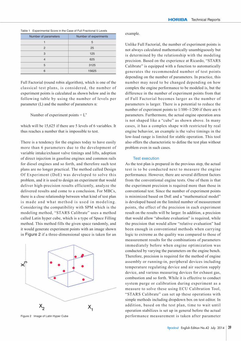
There is a tendency for the engines today to have easily more than 6 parameters due to the development of variable intake/exhaust valve timings and lifts, adoption of direct injection in gasoline engines and common rails for diesel engines and so forth, and therefore such test plans are no longer practical. The method called Design Of Exper iment (DoE) was developed to solve this problem, and it is used to design an experiment that would deliver high-precision results efficiently, analyze the delivered results and come to a conclusion. For MBCs, there is a close relationship between what kind of test plan i s ma de a nd what me t hod i s u sed i n model i ng. Considering the compatibility with SPM which is the modeling method, “STARS Calibrate” uses a method called Latin hyper cube, which is a type of Space Filling method. This method fills the given space randomly, and it would generate experiment points with an image shown in Figure 2 if a three-dimensional space is taken for an
example.
Unlike Full Factorial, the number of experiment points is not always calculated mathematically unambiguously but is determined by the relationship with the modeling precision. Based on the experience at Ricardo, “STARS Calibrate” is equipped with a function to automatically generates the recommended number of test points depending on the number of parameters. In practice, this number may need to be changed depending on how complex the engine performance to be modeled is, but the difference in the number of experiment points from that of Full Factor ial becomes larger as the number of parameters is larger. There is a potential to reduce the number of experiment points to 1/100~1/200 if there are 6 parameters. Furthermore, the actual engine operation area is not shaped like a “cube” as shown above. In many cases, it has a complex shape with restricted by real engine behavior, an example is the valve timings in the low-load range is limited for stable operation. This tool also offers the characteristic to defi ne the test plan without problem even in such cases.
Test executionAs the test plan is prepared in the previous step, the actual test is to be conducted next to measure the engine performance. However, there are several different factors from the conventional engine tests. One of them is that the experiment precision is required more than those in conventional test. Since the number of experiment points is minimized based on DoE and a “mathematical model” is developed based on the limited number of measurement points, the effect of the precision in each experiment result on the results will be larger. In addition, a precision that would allow “absolute evaluation” is required, while the precision that would allow “relative evaluation” had been enough in conventional methods when carrying logic to extreme as the quality was compared to those of measurement results for the combinations of parameters immediately before when engine optimization was conducted by varying the parameters on the engine bench. Therefore, precision is required for the method of engine assembly or running-in, peripheral devices including temperature regulating device and air suction supply device, and various measuring devices for exhaust gas, combustion and so forth. While it is effective to conduct system purge or calibration during experiment as a measure to solve these using ECU Calibration Tool, “STARS Calibrate” can set up these operations with simple methods including dropdown box on test editor. In addition, based on the test plan, t ime to wait until operation stabilizes is set up in general before the actual performance measurement is taken after parameter
Table 1 Experimental Score in the Case of Full Fractional 5 Levels
Number of parameters Number of experiments
1 5
2 25
3 125
4 625
5 3125
6 15625
Figure 2 Image of Latin Hyper Cube

40 English Edition No.42 July 2014
Feature ArticleApplication
Introduction of ECU Calibration tool, STARS Calibrate
change. However, setting this time too long by prioritizing t he me a s u r e me nt p r e c i s ion m ay r e s u l t i n long measu rement pe r iod pe r poi nt and dete r iora ted experiment efficiency. To balance these contradicting requirements at a high order, “STARS Calibrate” is equipped with a function to start measurement after checking that the measurement items have stabilized instead of simply depending on time as a standard function.
Another problem is that operation may be impossible in practice using the operating conditions defined in test plan due to engine misfire, knocking, excessive rise in exhaust temperature and so forth. In normal automatic operation, the test is paused and the engine stopped in general if such conditions occur. However, in experiments using MBC, large number of experiment points need to be operated even when test design is generated by DoE, and the efficiency drops considerably to pause the experiment and have the operator check every time. To solve this problem, “STARS Calibrate” is equipped with functions to
(1) Pause t he measu rement of poi nt s where operation is difficult and measure the following points, or
(2) Search for the combination of parameters for which experiment is possible instead of the combination of parameters defined by test plan regarding the points where operation is difficult, and measure under the substitute conditions,
and so forth according to the preset procedures so that the test can be continued automatically and efficiently without the check of the engineer in charge of experiment.
Modeling & assessmentAs described earlier, model generation can be considered the har t of MBC. While there are different meanings when we refer to “models” in engine development, the model in MBC is purely a “mathematical model” which does not s imulate the physica l or chemical phenomena. The model is also called Response Surface, and it can be said that its nature is close to that of the processes by the engineers to connect the discrete experiment results using French curves in the past (Figure 3). This model in MBC has the following general characteristics:
(1) T h e m o d e l i s p r e p a r e d individually for each engine pe r for ma nce such a s f uel
efficiency, HC concentration in exhaust gas and so on..
(2) T he model i s made by i nte r pola t i ng t he experiment results with some smooth curved surface instead of polygonal lines
(3) Therefore, the generated model does not always pass through the exper iment result points themselves. It is therefore possible that the original engine characteristics that are not affected by the noise in the experiment results too much can be expressed.
(4) Unlike French curves, surfaces can be formed in multidimensional directions regarding the parameters. Thus various different parameters as in the latest engines can be handled.
As a method to form this smooth curved surface, a quadratic polynomial had been adopted in the beginning due to the simplicity in handling and calculation load. However, some of the engine performance properties starts sudden dramatic changes from certain points such as knocking and coefficient of variance for combustion (CoV), and have become difficult to deliver sufficiently practical performance using quadratic polynomials from a certain point, in concurrence with the increase in parameters in the recent engines. While some adopt methods such as neural network and Radial Basis Function (RBF) as a method to solve this problem, it is necessary to carefully adjust the modeling conditions in order to deliver sufficiently practical precision, leaving some problems in terms of usefulness for the experiment operators. Compared to this, “STARS Calibrate” adopts a modeling method called Stochastic Process Models (SPM)
Figure 3 Display Example of Model Prepared with 3 Parameters (Blue solid line in figure indicates the model and red dotted lines indicate the confidence interval.)

41English Edition No.42 July 2014
Technical Reports
with good records at Ricardo. It is a developed form of a statistical method known as “Kriging” and “Design and Analysis of Computer Experiments (DACE),” and delivers the following characteristics:
(1) Relatively good modeling results are obtained even for measurement results with high noise.
(2) Precision is more easily obtained than other methods even when the number of experiment points is not very large.
(3) Highly non-linear engine performance that may suddenly change from a certain point can also be modeled.
(4) Setting is easy enough for anyone to deliver a model with good precision.
Of these, the results of comparison with a quadratic polynomial regarding calibration of engine characteristics that start changing suddenly from a certain point are shown in Figure 4. In addit ion, measures such as evaluating the precision and adjusting the model including deletion of abnormal measurement values as necessary or even conduct re-tests with increased experiment points or improved test precision in some cases will be necessary once the model has been prepared, before going on to the next step which is optimization using the model prepared as shown above, as the model precision affects the total precision of optimization. “STARS Calibrate” calculates the coefficient of determination (R2), root mean square error (RMSE) and so forth as a measure to evaluate the model precision not only between the model and actual measurement value but also on cross validation results. By also being equipped with the function to display the difference between model value and actual measurement value: residual error graphically, it is possible to make operations to exclude abnormal measurement results
directly from the model and so forth and regenerate the model.
OptimizationIn MBC, optimization is to determine the optimal combinations of parameters under finite number of engine operating conditions (rotational speed, load) using the “mathematical model” for engine performance prepared in the previous step. Since the engine performance can be estimated instantly under any engine control conditions (combinations of parameters) by preparing the model, it is possible to examine a wider range of combinations than actually operating the engine on an engine bench over a short time and to properly evaluate the interactions among various parameters or engine performances. As an example of this interaction evaluation, the conventional opt i m izat ion tools ana lyzed t he mult iobjec t ive optimization problems by introducing the concept called “evaluation function” as shown in an example below and substituting them as single objective optimization if there were multiple objective functions.
Evaluation function: Q (HC, NOx) = HC + kNOx
However, the problem with this conventional evaluation function was that the optimal solution varied by how coefficient k was adopted and that it was difficult to set up the k value “properly,” although it did indicate a trade-off. Therefore, many of the latest MBC tools present Pareto solutions as shown in Figure 5, from which the engineer can pick up the optimal point. This allows the engineer to intuitively determine to what range one performance can be improved without considerably compromising the other performance. “STARS Calibrate” utilizes Normal Boundary Intersection (NBI) method to generate this Pareto solution and is capable of calculating sufficiently
Figure 4 Model Comparison by Quadratic Equation and SPM
Figure 5 Pareto Solution Display of Double Objective Function (Blue solid line in figure indicates the Pareto solution and red circle the picked up optimal point.)
42 English Edition No.42 July 2014
Feature ArticleApplication
Introduction of ECU Calibration tool, STARS Calibrate
practical Pareto solution with much simpler settings than methods using the genetic algorithm (GA). In addition to this basic condition, there are many things to be considered in actual engine optimization other than the objective function. “STARS Calibrate” is capable of optimization with consideration of the following requirements:
(1) Res t r ic t ions i n pa ramete r variation range: Optimization can be conducted by narrowing d o w n t h e v a l v e t i m i n g variation to a certain range for example.
(2) Restrictions in performance values: Optimization can be conducted with consideration of the engine per formance modeled in the previous step, such as the knocking strength and the upper limit for the coefficient of variance for combustion (CoV).
(3) Optimization of overall mode: Optimization is possible with considerat ion of the overall restricting conditions for the mode such as upper limit value for HC emissions and so forth in mode addition in weighting addition mode with multiple steady conditions (e.g.: exhaust gas regulation mode for heavy vehicles or general-purpose engines).
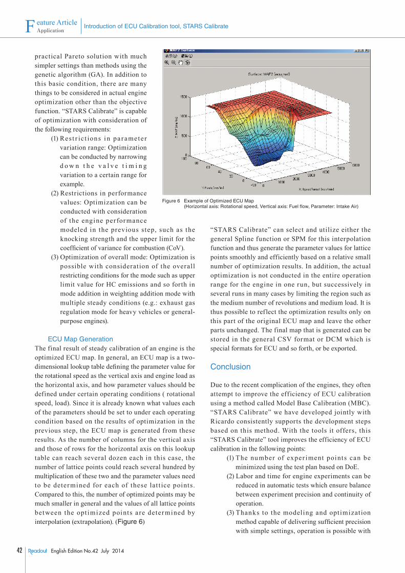
ECU Map GenerationThe final result of steady calibration of an engine is the optimized ECU map. In general, an ECU map is a two-dimensional lookup table defining the parameter value for the rotational speed as the vertical axis and engine load as the horizontal axis, and how parameter values should be defined under certain operating conditions ( rotational speed, load). Since it is already known what values each of the parameters should be set to under each operating condition based on the results of optimization in the previous step, the ECU map is generated from these results. As the number of columns for the vertical axis and those of rows for the horizontal axis on this lookup table can reach several dozen each in this case, the number of lattice points could reach several hundred by multiplication of these two and the parameter values need to be determined for each of these lat t ice points. Compared to this, the number of optimized points may be much smaller in general and the values of all lattice points between the opt imized points a re deter mined by interpolation (extrapolation). (Figure 6)
“STARS Calibrate” can select and utilize either the general Spline function or SPM for this interpolation function and thus generate the parameter values for lattice points smoothly and efficiently based on a relative small number of optimization results. In addition, the actual optimization is not conducted in the entire operation range for the engine in one run, but successively in several runs in many cases by limiting the region such as the medium number of revolutions and medium load. It is thus possible to ref lect the optimization results only on this part of the original ECU map and leave the other parts unchanged. The final map that is generated can be stored in the general CSV format or DCM which is special formats for ECU and so forth, or be exported.
Conclusion
Due to the recent complication of the engines, they often attempt to improve the efficiency of ECU calibration using a method called Model Base Calibration (MBC). “STARS Calibrate” we have developed jointly with Ricardo consistently supports the development steps based on this method. With the tools it offers, this “STARS Calibrate” tool improves the efficiency of ECU calibration in the following points:
(1) The number of exper iment points can be minimized using the test plan based on DoE.
(2) Labor and time for engine experiments can be reduced in automatic tests which ensure balance between experiment precision and continuity of operation.
(3) Thanks to the modeling and opt imizat ion method capable of delivering sufficient precision with simple settings, operation is possible with
Figure 6 Example of Optimized ECU Map (Horizontal axis: Rotational speed, Vertical axis: Fuel flow, Parameter: Intake Air)

43English Edition No.42 July 2014
Technical Reports
g o o d p r e c i s i o n f r o m t h e b e g i n n i n g of introduction and regardless of the operator.
As indicated in (3), what is most characteristic to it is that it provides a suffi ciently high precision without requiring the user to specify complex settings by adopting the latest methods including SPM. We hope that it will be utilized by many users and organizations.
Kazuhiro SHIOMIManagerPowertrain Business-OwnerCorporate & Segment Strategy DivisionHORIBA, Ltd.