ready preventative maintenance tune-ups chapter · preventative maintenance tune-ups chapter 14 ......
TRANSCRIPT

Preventative MaintenanceTune-ups
Chapter 14
Chapter 14—Preventative Maintenance Tune-ups 14-3
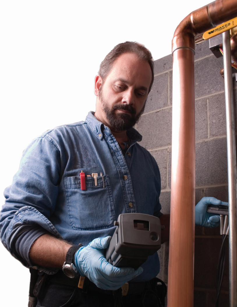
The preventive maintenance tune-up isthe most important service our industryoffers. A properly performed tune-upassures the customer that their heatingsystem is operating at peak safety, reliabil-ity, and efficiency.
Four key factors fora proper tune-up
• Safety
• Efficiency
• Reliability
• Cleanliness
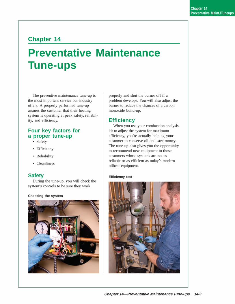
SafetyDuring the tune-up, you will check the
system’s controls to be sure they work
properly and shut the burner off if aproblem develops. You will also adjust theburner to reduce the chances of a carbonmonoxide build-up.
EfficiencyWhen you use your combustion analysis
kit to adjust the system for maximumefficiency, you’re actually helping yourcustomer to conserve oil and save money.The tune-up also gives you the opportunityto recommend new equipment to thosecustomers whose systems are not asreliable or as efficient as today’s modernoilheat equipment.
Checking the system
Efficiency test
Chapter 14Preventative Maint./Tuneups

14-4 Preventative Maintenance Tune-ups
Equipment integrityTypically, you may replace certain failed
parts (nozzles and filters); look for andcorrect potential problems; lubricatemotors; and check controls.
CleanlinessUnfortunately, most of the work you do
during a tune-up is not visible to thecustomer. An important part ofevery tune-up is to make sure thatwhat the customer does see—theoutside of the unit and the areaaround it—are neat and clean whenyou’ve finished.
By focusing on these four factorsduring the tune-up, you will saveyour customer money by minimiz-ing their fuel consumption and helpto avoid the inconvenience of anoilburner breakdown during theheating season.
Tools of the tradeTo successfully perform a tune-up, your
truck must have certain tools, instruments,
parts, and supplies. You need to have atleast the following:
A complete set of hand tools including:
• Standardwrenches—depending onthe type ofburners youservice, thesecan bestandard,metric or both.At a minimum, you will want to have aset of 1/4" through 3/4" standard openand box wrenches.
• Adjustable wrenches—an eight-inchand a ten-inch handle adjustablewrench.
• Socket wrench kit—1/4" to 3/4".
• Pliers—groove joint pliers (com-monly called water-pumps or channellocks), linesman pliers, locking pliers(Vise Grips®) and needle nose pliers.
• Allen wrenches (hex keys)—a standard set.
• Screwdrivers—an assortment ofslotted and phillips heads.
• Nut drivers—3/16", 1/4", 3/8" and 1/2".
• Wire cutter and stripper.
• Tubing cutters—3/4" regularand mini.
• Flaring tool.
• Flash light with spare batteries.
• Drop light.
• Jumper leads with insulatedalligator clips.
• Tape measure—12' minimum.
• Drill and drill bits.
Wiping down theboiler jacket
Keep your toolsneat in your truck
Chapter 14Preventative Maint./Tuneups
Chapter 14—Preventative Maintenance Tune-ups 14-5
For Riello Burnersyou’ll also want to have:
• 10mm and 12mm wrenches
• #4 and #5 Torx screw drivers
• 4mm and 5mm Allen wrenches (longand short handle)
Test equipment—pressure gauge,vacuum gauge, electric meter, and completeefficiency kit.
Vacuum cleaner, assorted adaptors andflue brushes.
Supplies—furnace cement, rags,cleaner, drip tray, builder’s paper or otherfloor covering.
As a professional, you should keep yourtools and supplies organized and in goodcondition. Not only will they serve youbetter, you will project the image of aprofessional.
Tune-up procedureThe following are the procedures for a
typical tune-up. Individual companies oftendevelop tune-up procedures that vary fromthese, so it is important that you followyour company’s policies and procedures.
This is an effective way to perform atune-up in a thorough, systematic manner.Although there may be circumstances thatmake it impossible to do all the operationsin the suggested sequence, we urge you tofollow this outline whenever possible.
Step 1. Customer Interview: Give yourcustomer a friendly and professionalgreeting. Courteously ask if they haveexperienced any problems or if they haveany questions. Listen carefully and addresstheir concerns.
Ask to see the thermostat and check forobvious problems. Check the heat anticipa-
tor setting, and make sure that it is leveland set 10 degrees above the room tem-perature. Listen for the burner and/orcirculator to start and then operate theemergency switch to be sure it worksproperly. Leave it in the off position.
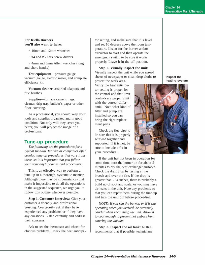
Step 2. Visually inspect the unit:Visually inspect the unit while you spreadsheets of newspaper or clean drop cloths toprotect the work area.Verify the heat anticipa-tor setting is proper forthe control and that limitcontrols are properly setwith the correct differ-ential. Note what kind offilter and pump areinstalled so you canbring the right replace-ment parts.
Check the flue pipe tobe sure that it is properlyscrewed together andsupported. If it is not, besure to include a fix inyour procedure.
If the unit has not been in operation forsome time, turn the burner on for about 5minutes to dry the heat exchanger surfaces.Check the draft drop by testing at thebreech and over-the-fire. If the drop isgreater than -.04 inches, there is probably abuild up of soot and scale, or you may haveair leaks in the unit. Note any problems sothat you can repair them during the tune-upand turn the unit off before proceeding.
NOTE: If you run the burner, or if it wasoperating when you arrived, be extremelycareful when vacuuming the unit. Allow itto cool enough to prevent hot embers fromentering the vacuum.
Step 3. Inspect the oil tank: NORArecommends that if possible, technicians
Inspect theheating system
Chapter 14Preventative Maint./Tuneups
14-6 Preventative Maintenance Tune-ups
check the oil tank for water during tune-up.If you find water in the tank report it toyour supervisor so arrangements can bemade for it to be removed and an investiga-tion made as to the source. Be sure totighten any tank plugs you may haveremoved while checking the tank for waterwhen you are finished. See Chapter 3 fortank inspection procedures and moreinformation on tank maintenance.
Step 4. Oil lines, valves, and filters:Shut off the oil valve andremove the filter canister—usea pan to collect the extra oil.Clean and check the filtercanister and replace thecartridge and gaskets. If youfind evidence of excessivesludge or water, notify yoursupervisor so corrective actioncan be scheduled.
Inspect the oil line for leaks,kinks or dents. If the line is rununderground check to be sure it
is made of coated copper or run in protec-tive tubing; if bare copper is run under-ground, report it to your office. Make surethere are no compression fittings. If youfind any, replace them with flare fittings.
Step 5. Fuel unit: Clean or replace thepump strainer, carefully scraping off theold gasket before installing a new one.
Open the valve, turn the switch on andbleed the unit. Run oil through a clear tubeinto a container until there are no visibleair bubbles. Check for leaks at the valvestem, filter, and the pump gasket.
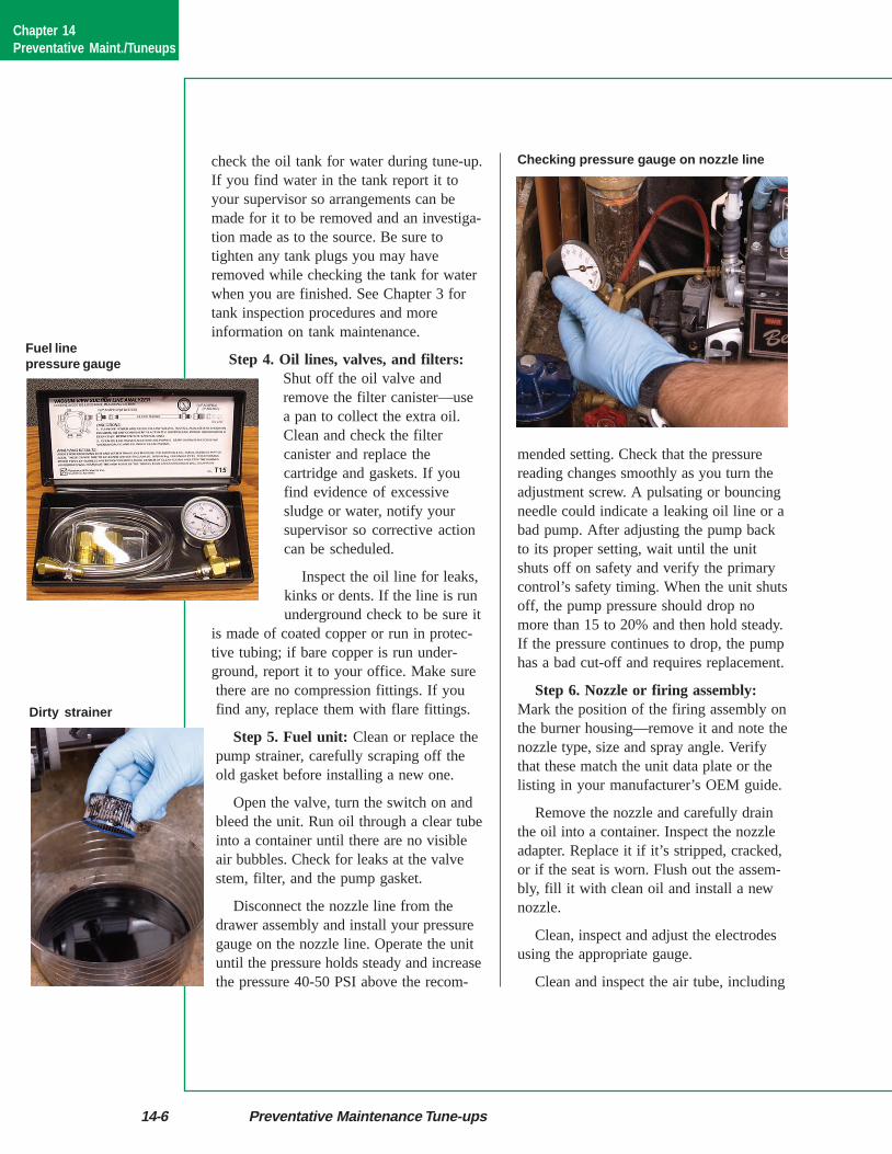
Disconnect the nozzle line from thedrawer assembly and install your pressuregauge on the nozzle line. Operate the unituntil the pressure holds steady and increasethe pressure 40-50 PSI above the recom-
mended setting. Check that the pressurereading changes smoothly as you turn theadjustment screw. A pulsating or bouncingneedle could indicate a leaking oil line or abad pump. After adjusting the pump backto its proper setting, wait until the unitshuts off on safety and verify the primarycontrol’s safety timing. When the unit shutsoff, the pump pressure should drop nomore than 15 to 20% and then hold steady.If the pressure continues to drop, the pumphas a bad cut-off and requires replacement.
Step 6. Nozzle or firing assembly:Mark the position of the firing assembly onthe burner housing—remove it and note thenozzle type, size and spray angle. Verifythat these match the unit data plate or thelisting in your manufacturer’s OEM guide.
Remove the nozzle and carefully drainthe oil into a container. Inspect the nozzleadapter. Replace it if it’s stripped, cracked,or if the seat is worn. Flush out the assem-bly, fill it with clean oil and install a newnozzle.
Clean, inspect and adjust the electrodesusing the appropriate gauge.
Clean and inspect the air tube, including
Fuel linepressure gauge
Dirty strainer
Checking pressure gauge on nozzle line
Chapter 14Preventative Maint./Tuneups
Chapter 14—Preventative Maintenance Tune-ups 14-7
the end cone slots and holes. Verify that theair tube is inserted to the correct position.
Reinsert the nozzle assembly into the airtube and secure it in place, making sure itis in the same position that you markedearlier.
Step 7. Burner motor, housing andfan: Remove the burner motor and checkthe burner housing for oil that couldindicate a loose fitting, cracked flare orleaking fuel pump seal.
If there are oilingpoints on the motor;lubricate each with3-4 drops of SAE 20non-detergent oil.Cooling slots shouldbe clear. Check themotor shaft for endplay; if it is exces-sive, replace themotor. Inspect theburner coupling to besure it is not worn orstripped. Clean theair inlets and fan
using a small brush. After you reinstall themotor, spin the fan a few times to makesure that the motor, fan and pump aremoving freely and that everything isproperly connected. Check all wires andconnections at the burner.
Step 8. Transformer and cad cell:Clean and check the transformer bushingsand springs. Inspect the ignition wires.Clean the cad cell eye and wires. Make surethe bracket is positioned correctly for goodflame sighting.
As you close the transformer, be sure theelectrodes are making solid contact with thetransformer springs and that no wires arebeing crimped.
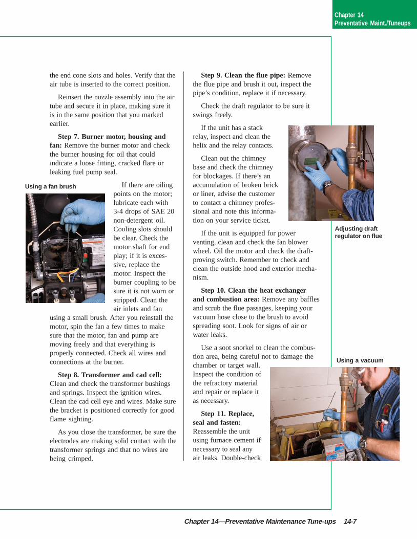
Step 9. Clean the flue pipe: Removethe flue pipe and brush it out, inspect thepipe’s condition, replace it if necessary.
Check the draft regulator to be sure itswings freely.
If the unit has a stackrelay, inspect and clean thehelix and the relay contacts.
Clean out the chimneybase and check the chimneyfor blockages. If there’s anaccumulation of broken brickor liner, advise the customerto contact a chimney profes-sional and note this informa-tion on your service ticket.
If the unit is equipped for powerventing, clean and check the fan blowerwheel. Oil the motor and check the draft-proving switch. Remember to check andclean the outside hood and exterior mecha-nism.
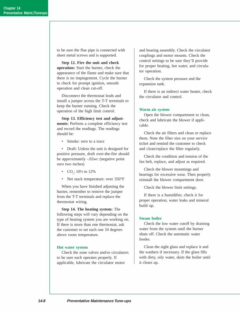
Step 10. Clean the heat exchangerand combustion area: Remove any bafflesand scrub the flue passages, keeping yourvacuum hose close to the brush to avoidspreading soot. Look for signs of air orwater leaks.
Use a soot snorkel to clean the combus-tion area, being careful not to damage thechamber or target wall.Inspect the condition ofthe refractory materialand repair or replace itas necessary.
Step 11. Replace,seal and fasten:Reassemble the unitusing furnace cement ifnecessary to seal anyair leaks. Double-check
Using a fan brush
Adjusting draftregulator on flue
Using a vacuum
Chapter 14Preventative Maint./Tuneups
14-8 Preventative Maintenance Tune-ups
to be sure the flue pipe is connected withsheet metal screws and is supported.
Step 12. Fire the unit and checkoperation: Start the burner, check theappearance of the flame and make sure thatthere is no impingement. Cycle the burnerto check for prompt ignition, smoothoperation and clean cut-off.
Disconnect the thermostat leads andinstall a jumper across the T-T terminals tokeep the burner running. Check theoperation of the high limit control.
Step 13. Efficiency test and adjust-ments: Perform a complete efficiency testand record the readings. The readingsshould be:
• Smoke: zero to a trace
• Draft: Unless the unit is designed forpositive pressure, draft over-the-fire shouldbe approximately -.02wc (negative pointzero two inches)
• CO2: 10½ to 12%
• Net stack temperature: over 350°F
When you have finished adjusting theburner, remember to remove the jumperfrom the T-T terminals and replace thethermostat wiring.
Step 14. The heating system: Thefollowing steps will vary depending on thetype of heating system you are working on.If there is more than one thermostat, askthe customer to set each one 10 degreesabove room temperature.
Hot water systemCheck the zone valves and/or circulators
to be sure each operates properly. Ifapplicable, lubricate the circulator motor
and bearing assembly. Check the circulatorcouplings and motor mounts. Check thecontrol settings to be sure they’ll providefor proper heating, hot water, and circula-tor operation.
Check the system pressure and theexpansion tank.
If there is an indirect water heater, checkthe circulator and control.
Warm air systemOpen the blower compartment to clean,
check and lubricate the blower if appli-cable.
Check the air filters and clean or replacethem. Note the filter size on your serviceticket and remind the customer to checkand clean/replace the filter regularly.
Check the condition and tension of thefan belt, replace, and adjust as required.
Check the blower mountings andbearings for excessive wear. Then properlyreinstall the blower compartment door.
Check the blower limit settings.
If there is a humidifier, check it forproper operation, water leaks and mineralbuild up.
Steam boilerCheck the low water cutoff by draining
water from the system until the burnershuts off. Check the automatic waterfeeder.
Clean the sight glass and replace it andthe washers if necessary. If the glass fillswith dirty, oily water, skim the boiler untilit clears up.
Chapter 14Preventative Maint./Tuneups
Chapter 14—Preventative Maintenance Tune-ups 14-9
Check the main vents and look forevidence of leaks.
When you have completed these steps,be sure to return all controls to their propersettings and double check to be sure thatyou removed any jumpers you may haveused.
Ask the customer to reset all thermostatsto their normal settings.
Step 15. Cleanup the work area: Onceyou’re satisfied that everything is workingproperly, use a garbage bag to remove oldparts, oil absorbent and newspaper or dropcloths so that nothing can fall out on yourway back to your truck. Use your vacuumcleaner to clean the area around the system.Return your tools to their proper places inyour truck and clean your hands.
Step 16. Double-check your work:Check your work area one last time. Pay
particular attention to potential sources ofoil leaks such as the filter canister, pump,burner housing and oil valve.
Step 17. Make it shine: Spend a fewmore minutes cleaning up. Wipe and cleanall of the external surfaces of the boiler orfurnace and work area. Use only clean ragsso you do not leave an odor behind.
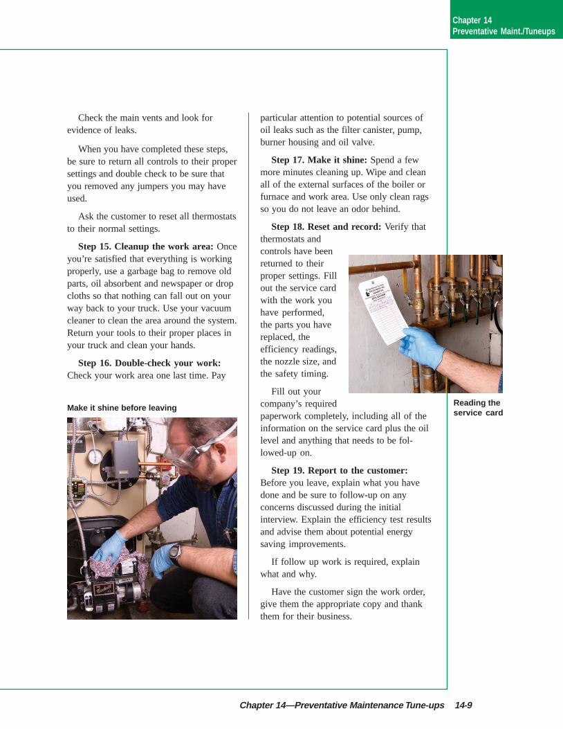
Step 18. Reset and record: Verify thatthermostats andcontrols have beenreturned to theirproper settings. Fillout the service cardwith the work youhave performed,the parts you havereplaced, theefficiency readings,the nozzle size, andthe safety timing.
Fill out yourcompany’s requiredpaperwork completely, including all of theinformation on the service card plus the oillevel and anything that needs to be fol-lowed-up on.
Step 19. Report to the customer:Before you leave, explain what you havedone and be sure to follow-up on anyconcerns discussed during the initialinterview. Explain the efficiency test resultsand advise them about potential energysaving improvements.
If follow up work is required, explainwhat and why.
Have the customer sign the work order,give them the appropriate copy and thankthem for their business.
Make it shine before leavingReading theservice card
Chapter 14Preventative Maint./Tuneups