real-time operating systems and software architecture for
TRANSCRIPT

Degree Project
Real-Time Operating Systems
and Software Architecture
for Next Generation’s UAV
Student: Johan Nyman (F02)
Company supervisor: Olivier Vanel
Tutor Supaero: Jacques Lamaison
Tutor LTH: Per Andersson
September 2007

Real-Time Operating System and Software Architecture in next generation’s UAV
Master thesis 2007 Johan Nyman Page 2 of 110
ACKNOWLEDGEMENTS
First of all I want to thank my supervisor at the company where I did this work, Mr. Olivier VANEL, who gave me the opportunity to carry out this internship. Your advice and introduction to the engineering process have been very helpful.
The work presented in this report would not have been possible without the contribution of many persons. In particular I want to thank Mr. Jean-David POMMEPUY who has provided a lot of help and guidance when it comes to avionics software, and all the norms and standards that applies.
On the hardware side, Mr. Gregory FREVA has never hesitated to provide his expertise, and to discuss the different combinations of hardware and software choices.
The software team, led by Mr. Jean-David POMMEPUY, including Didier LHOTE and Arnaud COURVOISIER, has provided their help and feedback whenever necessary.
I also want to thank the rest of the team that worked in my department at the company, for their availability and help when needed.
The reason I ever got here is because of the education provided by LTH and SUPAERO, thank you for that.
A special thanks goes to J-L GONNAUD at EADS, responsible for the Airbus A400M IMA integration, who explained some of the particularities of IMA, and conditions that applies to the certification of the system.

Real-Time Operating System and Software Architecture in next generation’s UAV
Master thesis 2007 Johan Nyman Page 3 of 110
ABBREVIATIONS
ADU Air Data Unit
AFDX Avionics Full DupleX switched Ethernet
APEX APplication/EXecutive
API Application Programming Interface
ARINC Aeronautical Radio Incorporated
ARP Aerospace Recommended Practice
BAT Block Address Translation
BSP Board Support Package
COTS Commercial Off The Shelf
cPCI compact PCI
CPU Central Processing Unit
CSP CPU Support Package
DKM Downloadable Kernel Module
FAA Federal Aviation Authority
FIFO First In First Out
GCS Ground Control Station
HM Health Monitor
HNS Hybrid Navigation System
IDE Integrated Development Environment
IEEE Institute of Electrical and Electronics Engineers
IMA Integrated Modular Avionics
I/O Input(s)/Output(s)
IOU Input/Output Unit
ISR Interrupt Service Routine
JAR Joint Airworthiness Requirements
JSF Joint Strike Fighter
JTAG Joint Test Action Group
J-UCAS Joint Unmanned Combat Aerial System
KDI Kernel Downloadable Image
LRM Line Replaceable Module
LRU Line Replaceable Unit
MCCU Mission and Critical Computer Unit
MISRA Motor Industry Software Reliability Association
MMU Memory Management Unit
NDA Non Disclosure Agreement
OS Operating System
PCB Printed Circuit Board

Real-Time Operating System and Software Architecture in next generation’s UAV
Master thesis 2007 Johan Nyman Page 4 of 110
PCI Peripheral Component Interconnect
PGU Piloting/Guidance Unit
PMT Processeur Multi Technique
POSIX Portable Operating System Interface for computer environments
PTE Page Table Entry
PXE Pre-boot eXecution Environment
ROS Rules Of Security
RPC Remote Procedure Call
RSC Reusable Software Component
RTCA Radio Technical Commission for Aeronautics
RTOS Real-Time Operating System
RTP Real Time Process
TFTP Trivial File Transfer Protocol
UAV Unmanned Aerial Vehicle
VCT Virtual machine Configuration Table
VM Virtual Machine
VME Versa Module Eurocard
GLOSSARY
Host Machine used to develop the software
Cross compiler Used on host to produce object code executable on target.
Emulator Entity accepting the same input and producing the same output as a given system, using the same object code.
Native compiler Compiles on host to execute on host. Used for development.
Simulator Same as emulator but with different (derived) object code.
Smart actuator An “intelligent” actuator in the sense that it receives a reference value and then uses a closed control loop to reach and maintain this value itself.
Target Machine used to execute the software
Test bed Permits to run equipment while simulating its environment.

Real-Time Operating System and Software Architecture in next generation’s UAV
Master thesis 2007 Johan Nyman Page 5 of 110
CONTENTS
PART A: INTRODUCTION............................... ...................................................................9
A 1 Introduction....................................... ..............................................................................................9 A 1.1 Document Outline ......................................................................................................................9 A 1.2 Scope.........................................................................................................................................9 A 1.3 Problem formulation .................................................................................................................10 A 1.4 Methodology used....................................................................................................................11 A 1.5 Realization ...............................................................................................................................11
PART B: APPLICABLE NORMS, STANDARDS AND CONSTRAINTS IN AVIONICS ..13
B 1 DO-178B ........................................................................................................................................13 B 1.1 Reusable Software Component, RSC......................................................................................13
B 2 Integrated Modular Avionics ........................ ...............................................................................14 B 2.1 Background ..............................................................................................................................14 B 2.2 The concept of Integrated Modular Avionics ............................................................................15 B 2.3 IMA Particularities ....................................................................................................................17 B 2.4 Certification Aspects ................................................................................................................20 B 2.5 Isolation and Independence between partitions .......................................................................20
B 3 Constraints........................................ ............................................................................................21 B 3.1 Hardware..................................................................................................................................21 B 3.2 Certification ..............................................................................................................................21 B 3.3 Industrial...................................................................................................................................21
PART C: REAL TIME OPERATING SYSTEMS ................ ...............................................23
C 1 Real-Time Operating Systems........................ .............................................................................23 C 1.1 Worst Case Scenarios .............................................................................................................24 C 1.2 Complete Operating System or Simple Scheduler?.................................................................24 C 1.3 The Board Support Package....................................................................................................25 C 1.4 Make or Buy? ...........................................................................................................................26
C 2 Criteria for choosing RTOS ......................... ................................................................................26 C 2.1 Perennity ..................................................................................................................................27 C 2.2 Norms and Standards ..............................................................................................................27 C 2.3 Supported Hardware ................................................................................................................28 C 2.4 Development ............................................................................................................................28 C 2.5 Design ......................................................................................................................................29 C 2.6 Functionality .............................................................................................................................29 C 2.7 Performance.............................................................................................................................31 C 2.8 Cost..........................................................................................................................................32 C 2.9 References...............................................................................................................................33 C 2.10 Ease of Use..............................................................................................................................33
C 3 Conclusion on CRITERIA.............................. ...............................................................................33
C 4 COTS OS .......................................................................................................................................34 C 4.1 VxWorks 6.3/CERT/AE 653 .....................................................................................................35 C 4.2 INTEGRITY-178B ....................................................................................................................35 C 4.3 LynxOS-178 .............................................................................................................................37

Real-Time Operating System and Software Architecture in next generation’s UAV
Master thesis 2007 Johan Nyman Page 6 of 110
C 4.4 CsLEOS ...................................................................................................................................37 C 4.5 µC/OS-II ...................................................................................................................................38
C 5 In-house OS ........................................ ..........................................................................................39 C 5.1 DMS .........................................................................................................................................39 C 5.2 APEX........................................................................................................................................40
C 6 Conclusion ......................................... ...........................................................................................40
PART D: PROTOTYPE FLIGHT COMPUTER .................. ...............................................46
D 1 Feedback from the existing UAV..................... ............................................................................46
D 2 Software “Wishlist” for the new UAV ................. ........................................................................46
D 3 Functional Architecture of the new UAV ............. .......................................................................47 D 3.1 Functional Specification ...........................................................................................................47 D 3.2 The Control Chain ....................................................................................................................47 D 3.3 Function Separation .................................................................................................................48
D 4 Hardware ........................................... ............................................................................................50 D 4.1 The Avionics System................................................................................................................50 D 4.2 The Mission and Critical Computer Unit...................................................................................51 D 4.3 The PMT board ........................................................................................................................52
D 5 Software architecture ............................... ....................................................................................52 D 5.1 ARINC Implementation with LynxOS-178 ................................................................................54 D 5.2 VxWorks implementation .........................................................................................................56
D 6 Certification Impact on the Software Architecture .. ..................................................................57
D 7 Porting of Software from the existing UAV to the new UAV.....................................................59 D 7.1 Different avionics architecture..................................................................................................59 D 7.2 Different sensors/actuators ......................................................................................................59 D 7.3 Different transmissions.............................................................................................................60 D 7.4 Different OS .............................................................................................................................60
D 8 The Prototype Flight Computer...................... .............................................................................60
PART E: CONCLUSIONS AND FUTURE WORK ................ ............................................61
PART F: BIBLIOGRAPHY ............................... .................................................................63
PART G: APPENDIX A – TASK SPECIFICATION ............ ..............................................66
G 1 Parameter Management and Failure Detection.......... ................................................................66 G 1.1 Physical resources: ..................................................................................................................66 G 1.2 Input/Output: ............................................................................................................................67 G 1.3 High level algorithm:.................................................................................................................67
G 2 Data Verification ................................... ........................................................................................67 G 2.1 Physical resources: ..................................................................................................................67 G 2.2 Input/Output: ............................................................................................................................68 G 2.3 High level algorithm:.................................................................................................................68
G 3 Critical Navigation ................................ ........................................................................................68 G 3.1 Input/Output: ............................................................................................................................68

Real-Time Operating System and Software Architecture in next generation’s UAV
Master thesis 2007 Johan Nyman Page 7 of 110
G 3.2 High level algorithm:.................................................................................................................69
G 4 Supervision ......................................... ..........................................................................................69 G 4.1 Physical resource:....................................................................................................................69 G 4.2 Input/Output: ............................................................................................................................69 G 4.3 High level algorithm:.................................................................................................................70
G 5 Guidance ........................................... ............................................................................................70 G 5.1 Input/Output: ............................................................................................................................70 G 5.2 High level algorithm:.................................................................................................................70
G 6 System Surveillance and Failure Management........... ...............................................................70 G 6.1 Input/Output: ............................................................................................................................71 G 6.2 High level algorithm:.................................................................................................................71
G 7 Piloting and Propulsion .............................. .................................................................................71 G 7.1 Physical resources: ..................................................................................................................72 G 7.2 Input/Output: ............................................................................................................................72 G 7.3 High level algorithm:.................................................................................................................72
G 8 Recovery ........................................... ............................................................................................72 G 8.1 Physical resources: ..................................................................................................................72 G 8.2 Input/Output: ............................................................................................................................73 G 8.3 High level algorithm:.................................................................................................................73
G 9 Communications ..................................... .....................................................................................73 G 9.1 Physical resource:....................................................................................................................73 G 9.2 Input/Output: ............................................................................................................................74 G 9.3 High level algorithm:.................................................................................................................74
G 10 Mission Navigation................................. ......................................................................................74 G 10.1 Physical resource:....................................................................................................................74 G 10.2 Input/Output: ............................................................................................................................75 G 10.3 High level algorithm:.................................................................................................................75
G 11 Payload Management .................................. .................................................................................75
G 12 Equipment Management ................................ ..............................................................................75
G 13 Maintenance........................................ ..........................................................................................75
G 14 Common Algorithms .................................. ..................................................................................76 G 14.1 Algorithm to empty buffers (and queuing ports) .......................................................................76 G 14.2 Algorithm to check sampling ports (and blackboards)..............................................................76
PART H: APPENDIX B – VXWORKS 6.3 EVALUATION ........ ........................................78
H 1 Introduction....................................... ............................................................................................78
H 2 VxWorks 6.3/CERT/AE 653 overview ..................... .....................................................................78
H 3 User Evaluation ..................................... .......................................................................................79 H 3.1 Evaluation Environment description .........................................................................................80 H 3.2 Evaluation ................................................................................................................................82
H 4 Performance......................................... .........................................................................................88

Real-Time Operating System and Software Architecture in next generation’s UAV
Master thesis 2007 Johan Nyman Page 8 of 110
H 5 Conclusion ......................................... ...........................................................................................89
H 6 Synthetic Evaluation of VxWorks 6.3................... .......................................................................89
PART I: APPENDIX C – LYNXOS-178 EVALUATION ......... ...........................................91
I 1 Introduction....................................... ............................................................................................91
I 2 LynxOS-178 OVERVIEW.................................. .............................................................................91
I 3 User Evaluation ..................................... .......................................................................................92 I 3.1 Evaluation Environment description .........................................................................................92 I 3.2 Evaluation ................................................................................................................................94
I 4 Performance......................................... .......................................................................................102 I 4.1 Context Switch Time ..............................................................................................................102 I 4.2 Interrupt Response Time........................................................................................................102
I 5 Conclusion ......................................... .........................................................................................103
I 6 Synthetic Evaluation of LynxOS-178 ................... .....................................................................103
PART J: APPENDIX D – RTOS INFORMATION GATHERED ..... .................................105

Real-Time Operating System and Software Architecture in next generation’s UAV
Master thesis 2007 Johan Nyman Page 9 of 110
PART A: INTRODUCTION
A 1 INTRODUCTION
This master thesis was conducted at one of the world’s leading tactical UAV manufacturers from April 2 2007 until September 28, 2007. It will be presented at the French Engineering School for Aeronautics and Space (Ecole Nationale Supérieure de l’Aéronautique et de l’Espace) in Toulouse, France, the 6th of September 2007, and at Lund Institute of Technology in Lund, Sweden, the 9th of October 2007.
A 1.1 DOCUMENT OUTLINE
The first part (A) of this document is an introduction and concerns the background for this work, methodology, scope and goals.
Part B treats the constraints that dictate some of the choices that had to be made during the avionics software conception. It should also give the reader an understanding of concepts and terminology, which is then used throughout the document, notably about certification and IMA.
Part C treats Real-Time Operating Systems. The first chapters define the criteria of choice for a new real time operating system to use in the new UAV. These criteria come from literature [R4], [R14 – R16], [R18 – R21] and information gathered during meetings with software vendors. An evaluation of commercial and in-house RTOS then follows.
Part D describes the development of the prototype flight computer. First, the functional architecture, then the hardware architecture, which is necessary to take into account when elaborating the software architecture. The elaboration of the software architecture and the choices that have been made are then discussed.
Part E contains the conclusion.
Part F gives a list of literature and web pages used during this project.
Appendix A (part G) gives the specification of the tasks that have to be implemented in the UAV.
In Appendix B (part H), the complete user evaluation of VxWorks 6.3 is reported.
In Appendix C (part I), the evaluation of LynxOS-178 is reported.
Appendix D (part J) is a table with all the information gathered about those real-time operating systems that were examined during this work.
A 1.2 SCOPE
The principal purpose of a tactical UAV is to observe and provide information without risking human life. In fact, the UAV is just a small part of a bigger system. The UAV is controlled by

Real-Time Operating System and Software Architecture in next generation’s UAV
Master thesis 2007 Johan Nyman Page 10 of 110
a ground station, which is in contact with the headquarter. The word tactical implies that it is not primarily a weapon, but a help for decision-making.
An example of a tactical UAV has a payload consisting of a gyro-stabilized platform with an IR and a Daylight TV camera (near infrared). There is also a fixed color TV-camera known as the “pilot-camera”. For deployment of the UAV system, there is no need for an airfield, since the aircraft has no landing gear. It is catapulted to take off, and recovery is ensured by deploying a parachute and airbags. It can therefore operate from almost anywhere.
The company where this work took place develops and maintains a UAV system, operational since 1999 and sold to several countries. It is of interest to increase performance, operational margins, and to be able to fly in civilian airspace, instead of being restrained to field operations or flight test areas. The existing airframe and avionics system cannot evolve much further, and it has therefore been decided to develop a whole new UAV. In the framework of the development of this next generation’s UAV, in this report referred to as “the new UAV”, a new flight computer with accompanying software must be developed.
The previous flight computer suffers from limitations on calculating capacity and memory. The software is hampered by complicated maintenance and is difficult to expand with further functions. Therefore, a new conception has to be introduced. Furthermore, the new UAV should be able to fly in civilian airspace, and must therefore be certified to the norm Stanag 4671 (UAV Systems Airworthiness Requirements) [R17], which implies that the software must be conformant with the norm DO-178B level C.
Modularity of the software, and the possibility for future upgrades in hardware, is greatly simplified by using an abstraction layer between the software application and the hardware material. This layer is the operating system, which must be strictly real-time and conformant with the abovementioned norm.
During this internship, I have examined several such operating systems, and developed a proposition for a modular software architecture. In parallel, the avionics hardware has been defined by the engineers at the company. An implementation of the software architecture, using empty functions but with communication between modules in place, has then been tested on the new avionics hardware.
A 1.3 PROBLEM FORMULATION
The purpose of this work is threefold. What is needed in the end is a system which is modular, easy to upgrade and certifiable. Therefore, the scope goes beyond the software application, and the system as a whole has to be considered. The parts regarding the software also include hardware aspects and interactions. An intermediate layer, the operating system, can handle such interactions in order to decrease the coupling between application and material. The thesis work was therefore divided into the following parts:
1) Investigate which real-time operating system is the most suitable for use in the new UAV. The following aspects are to be considered: certification, partitioning, and real-time performance. This part began with a bibliographical research, where the criteria of choice for the RTOS to use in the new UAV were defined, and a preliminary scan of existing RTOS. A user evaluation of two of them was conducted after further information had been gathered.

Real-Time Operating System and Software Architecture in next generation’s UAV
Master thesis 2007 Johan Nyman Page 11 of 110
2) Develop a certifiable, modular software architecture for the new UAV. Investigate the impact of the certification constraint, and in particular, answer the following question: can partitions of different criticality communicate both ways and still be certified?
3) Develop a prototype flight computer to test the RTOS and implement the SW architecture.
A 1.4 METHODOLOGY USED
Different types of research and methodological approaches are well explained in [R41]. Throughout this project I have used a hermeneutic approach, according to [R41]. Facts gathered are subjective, and colored by the author’s interpretation. The investigation is of an explorative type, since it aims to fill out gaps of knowledge, but also of normative type, since a plan for continued development is proposed [R41] (i.e. choice of RTOS and software architecture). Furthermore, the research can be said to be of a qualitative and inductive type. Qualitative, since no data can be expressed in quantities, and inductive, since no pre-existing theory was tested [R41].
A 1.5 REALIZATION
For the research about Real-Time Operating Systems, I have first gathered data using Internet, talking to vendor representatives, and discussing with experienced engineers who have experience of real-time application development. Together with this, and introducing the constraints of the new UAV project, the criteria of choice have been defined and ranked. Contact was taken with the distributors of those RTOS found consistent with our needs, in order to get more information. A practical user evaluation was then performed to have a personal experience with some of the operating systems.
Considering the software architecture, I began by studying what exists today. The feedback from the existing UAV, and desires from persons working with the new avionics, gave me ideas of what would be good to include and what must necessarily change from the previous software architecture. New ideas were introduced, under the given constraints. The process leading to a functional architecture took several iterations. This functional architecture was then adapted for the given hardware and the chosen OS, and thus transformed to a software architecture, using features such as tasks, semaphores and message queues provided by the OS.
Integrated Modular Avionics described by ARINC norms 651 [R5] and 653 [R3], and the norm DO-178B [R1] for software certification are two main themes running through all avionics development today. A thorough understanding of these concepts was needed in order to advance with both the RTOS evaluation and the software design. Consequently, they were carefully studied before beginning any development.
The choice of RTOS and elaboration of the functional architecture have been done in parallel, before advancing with the software architecture and the actual implementation. The following figure (Fig. 1) shows the process:

Real-Time Operating System and Software Architecture in next generation’s UAV
Master thesis 2007 Johan Nyman Page 12 of 110
Fig. 1: The process followed during this thesis wor k
IMA (ARINC 651, 653)
DO-178B
Prototype HW+SW+OS
Specifications
Hardware
Certification
User evaluation
Evaluation of information
Criteria of choice
Bibliographic study
RTOS
Software Architecture
Contact with vendors
Functional Architecture

Real-Time Operating System and Software Architecture in next generation’s UAV
Master thesis 2007 Johan Nyman Page 13 of 110
PART B: APPLICABLE NORMS, STANDARDS AND CONSTRAINTS IN AVIONICS
B 1 DO-178B
Software Considerations in Airborne Systems and Equipment Certification, also known as the RTCA DO-178B norm, in Europe called Eurocae ED-12B, consists of guidelines for software certification [R1]. It treats the development, lifecycle, and validation considerations of software used in onboard systems, in order to comply with airworthiness requirements. In particular it specifies that every line of code should be directly traceable to a requirement and a test routine, and that no extrane ous code outside of this process should be included. This traceability simplifies future evolutions, and makes sure that if one requirement changes, only the code affected by this requirement is modified, and nothing else.
This process minimizes the error introduced by verifying the coherence at each level of development between the intentions, what is being done, what has been done, and the result. In this way, there shall be no anomalies introduced during development.
The norm divides software into five different classes of safety criticality. These classes range from A through E, corresponding to the consequence an eventual error has. In JAR25 terminology class A corresponds to “catastrophic”, B to “hazardous”, C to “major”, D to “minor” and E without effect. Consequently, class E is not treated by the norm.
The software is part of a bigger system. Developing the code to level A is of no use if the underlying hardware has glitches. Therefore, the hardware should be developed to the same safety level as the most critical software running on it. The corresponding hardware norm is RTCA DO-254 (identical with Eurocae ED-80). The final product is tested on its real hardware, within its real environment.
When talking about certification, this generally means airworthiness certification of the final product, which implies software conformant with DO-178B. It is not true however, that software conformant with DO-178B means that the system as a whole is certifiable. In everyday language, “software certification to DO-178B“ is a part of the complete airworthiness certification process.
B 1.1 REUSABLE SOFTWARE COMPONENT, RSC
The FAA, which is the airworthiness certification authority in the United States, has embraced the concept of “Reusable Software Component”. A software classed RSC has been certified and it has been proven that its behaviour remains unchanged when its environment changes. It can thus be re-used in another application without any additional certification effort. Using RSC-classed software is therefore much cheape r than having to recertify every part of the code [R23].
Airworthiness certification by the FAA in the United States is generally sufficient to fly elsewhere, but sometimes the European certification authority, EASA, wants to do their own audits to confirm that the software has met all the requirements. The process for gaining

Real-Time Operating System and Software Architecture in next generation’s UAV
Master thesis 2007 Johan Nyman Page 14 of 110
software and system approvals in the US and Europe are somewhat different, so there will be some paperwork required to transfer DO-178B credit in Europe, but the certification risk is much lower if the system has been approved in the United States. Furthermore, EASA has not formally recognized the RSC concept, but they are aware of its existence, and much resistance by the European auditors is not expected. In the future, the EASA is expected to formally embrace the RSC process.
B 2 INTEGRATED MODULAR AVIONICS
B 2.1 BACKGROUND
Federated architecture, which is used in current aircraft’s digital flight-controls as described by Gouley [R6], uses different computers to implement different functions. Auto-pilot, yaw-damping, flight management and display system all have their own computer system, and are only loosely coupled since their interactions are performed by the exchange of data. Fault containment is direct, since an erroneous computer cannot propagate its malfunction to another computer. Functions can be designed to detect an erratic data source to stop the propagation by data flow, and a faulty com puter unit can easily be taken offline. The modules, which contain all the necessary resources for the function to be performed, are called Line Replaceable Units, LRUs. An example of LRUs and their complicated interconnections are described in Fig. 2
Flight Control
Weather central
FADEC
Flight Management and Guidance
Navigation equipment
Displays and Controls
Autopilot
ILS
VOR
Air data computer
Air sensors
actuators
Sensors
Engine sensors
VOR antenna
Weather radar
Fig. 2: Federated Architecture
Integrated Modular Avionics, IMA, described by Gouley [R6], is becoming increasingly used amongst aircraft manufacturers. IMA reduces the number of equipments and length of cables in aircraft (thus weight) while providing modularity for further development and the use of standardized COTS to reduce development costs. This is done by having racks of computer units in the aircraft, that are similar in conception (thus reducing cost), and that can host any application whichever (thus providing modularity). The different equipments communicate on a multiplexed data bus (see Fig. 3).

Real-Time Operating System and Software Architecture in next generation’s UAV
Master thesis 2007 Johan Nyman Page 15 of 110
In IMA, several functions share the same computing resource. Erroneous software has the potential to damage all the other functions, since it shares the same processor unit and I/O. Software partitioning in space and time is used to r estore the protection against fault propagation, equivalent to that which is inherent i n the federated architecture.
FADEC
Inertial navigation
system
Data concentrator
Air
sen
sors
actuators
Sensors
Engine sensors
VO
R a
nte
nna
Wea
the
r ra
dar
Data bus
Flight Control
Displays and ControlsAutopilot
Air data unit
free
Cabinet 2
Weather centralFlight
Management & Guidance
ILSVOR
free
Cabinet 1
Fig. 3: Integrated Modular Avionics
B 2.2 THE CONCEPT OF INTEGRATED MODULAR AVIONICS
Integrated Modular Avionics design replaces ARINC 700 series avionics, consisting of LRUs, in airplanes designed after 1990. It is based on the concept of powerful computers (servers) with an Operating System that allows several applications to run on the same hardware, with robust partitioning so that each application can be considered isolated from the others [R5]. The computer is housed in a hardware cabinet together with I/O modules, sharing the same power supply, fault tolerance processing, and chassis. The modules are called Line Replaceable Modules, LRMs. The internal configuration of different cabinets may differ within the same aircraft, depending on the diversity, complexity, and criticality of the functions supported by each cabinet, but the principle remains the same: that several functions share the same hardware resources . Several cabinets are interconnected in a network by ARINC 629 data buses. The interface to the outside world, such as sensors, actuators, displays and radio antennas are also connected to the cabinets via the data bus. Most of the aircraft functions are implemented in software in the ADA language, and sharing the same common hardware architecture. IMA is a modular system providing shared resources for the various functions implemented in software [R6].
Redundancy and physical separation is possible within or between the cabinets [R5]. The hardware modules are shared resources between the applications, but robust partitioning separates the aircraft functions. Applications on a faulty cabinet can also be made able to migrate to another, thanks to the standardized hardware interface.

Real-Time Operating System and Software Architecture in next generation’s UAV
Master thesis 2007 Johan Nyman Page 16 of 110
Simple I/O such as digital switches comes through a data concentrator, which pre-processes the data and interfaces with the data bus. This minimizes discrete wiring and improves aircraft maintainability since monitoring of signals is simplified. More complex components, for example the air data unit or the inertial navigation unit will have input and output contacts and data format that are directly compatible with the data bus [R5].
The hardware building blocks are standardized, and the LRMs can be used in several different aircrafts. It is the aircraft integrator that decides which software application will run in a specific cabinet, thereby specifying the cabinets’ avionic functionality [R5]. Specific aircraft software, such as the flight commands and equipment management are then developed for a unique aircraft, but to a common interface (API), the ARINC 653 APEX. Standardized software such as the navigation position determination function can easily be re-used in another aircraft, thanks to the standard API and hardware.
IMA comes as a response to the request from the airlines on reduced life-cycle cost. This will be achieved thanks to the following aspects, which are all addressed by the IMA concept [R5]:
– Reduced weight (less equipments, less cables)
– Reduced volume (shared resources, less number of computers, each with their own I/O, power module and chassis)
– Lower initial cost (standard components, larger series for avionics manufacturers, less specific equipments)
– Improved reliability (fault containment)
– Improved flexibility (modular design, interchangeable hardware)
– Improved maintainability (standard components, scheduled maintenance, software modification without sending back equipment to factory)
– Easier certification (partitioning)
B 2.2.1 Software considerations
An application consists of processes or tasks executing following their priority. The language recommended to use for the applications is ADA, but with some restrictions [R5]:
– Tasks are not allowed to be created dynamically
– All memory is allocated at initialization (no dynamic memory allocation)
– Exception handling is difficult to implement (less determinism).
It is necessary to use an operating system equivalent to a multi-user/multitasking system. The OS should be certifiable and provide robust partitioning assuring the separation of the applications. It should also provide the standard API specified in ARINC 653. The OS interfaces with the hardware, making the application hardware independent.
B 2.2.2 Norms and directions
There are several ARINC norms that treat different aspects of IMA:
– ARINC report 651: “Design Guidance for Integrated Modular Avionics” [R5], describes the general concept of IMA.

Real-Time Operating System and Software Architecture in next generation’s UAV
Master thesis 2007 Johan Nyman Page 17 of 110
– ARINC 653: “Avionics Application Software Standard Interface” [R3], describes the software interface, the APEX.
– ARINC Specification 659: “Backplane Data Bus” [R8], describes (as suggested by the title) the backplane data bus. Airbus however, does not use this. They use USB 1.1 as backplane data bus [R6]. The advantage is that the bus controller is commercially widespread, inexpensive and available on almost every COTS card on the market.
– ARINC Specification 629: “Multi-transmitter Data Bus” [R9], describes the inter-cabinet and equipment data bus. Once again, Airbus uses another standard: the AFDX bus [R6]. Normalisation of this is coming in ARINC 664 Part 7 [R11].
– ARINC Specification 650: “Integrated Modular Avionics Packaging and Interfaces” [R10] describes hardware packaging standards and connectors.
– ARINC report 613: “Guidance for using the ADA programming language in avionic systems” [R12], describes the usage of ADA, recommended software high-level language.
B 2.3 IMA PARTICULARITIES
With an equipment-centered federated architecture, where each equipment is separated from the others and does its own calculations, fault containment and isolation is natural. In IMA, partitioning is the way to provide the same characteristics, when the applications share the calculating resource. This includes:
– Independence of software components and processes
– Error containment
One of the most important aspects of IMA is that partitioning in space and time makes it possible to have applications of different levels of safety criticality running on the same computer unit. This way, a safety-critical application sharing a processor with a non-safety critical application can be conformant with DO-178B and certified without taking both applications into consideration in the certification process [R5]. Physical segregation, for example one computer unit hosting the critical code and another hosting the non-critical code, is NOT necessary. This can be done thanks to partitions of different levels of security, since it is impossible for an unsafe application that is erroneous in one partition to influence any other partition. This concept is illustrated by the following image (Fig. 4).

Real-Time Operating System and Software Architecture in next generation’s UAV
Master thesis 2007 Johan Nyman Page 18 of 110
Secure Partition 1ADA ProgramSafety Level: A
Secure Partition nC Program
Safety Level: E(Unsafe)
FAILURE !
Secure Partition 2C Program
Safety Level: C
ARINC 653 APEX
Embedded Processor
DO-178B Certified Kernel
NO EFFECT!
Fig. 4: Brick wall partitioning between application s
B 2.3.1 Partitioning in Space
The partitioning in space is physically provided by the Memory Management Unit (MMU) in the CPU. But it has to be supported by the OS. Each process gets its own protected memory zone in which it resides, and there is no way to read or write outside. If a process tries, it will immediately be terminated. This considerably increases the stability of the system, and prohibits the most difficult bugs which occurs when a program write in another program’s memory. The price to pay is slightly reduced performance since CPU cycles must be used to change the context of the MMU at each context-switch. But this usage of the MMU can also simplify the development of a high availability system. In fact, one erroneous process can easily be restarted without affecting the rest of the system [R24].
B 2.3.2 Partitioning in Time
Time partitioning is provided by the ARINC scheduler, which is a part of those operating systems conformant with ARINC 653. Each process is given a guaranteed time-slot to execute on the CPU, following a pre-made schedule, called “major time frame”. This partitioning guarantees that an erroneous process cannot use more CPU-time than what has been allocated to it.
This major frame has to be adapted to the applications with the strictest real-time constraints (a multiple of the shortest period). This makes it necessary to give an allocation in time for every application early on in the conception. Big margins should be given to each application in order to allow future changes. The partitioning makes it possible to re-certify only the application that has changed, but if the major time frame has to be changed all applications need to be re-certified [R22].
B 2.3.3 Health Monitoring
The Health Monitor (HM) is a part of the OS and is responsible for monitoring and reporting both hardware and software faults and failures. This helps to isolate faults and stop failure

Real-Time Operating System and Software Architecture in next generation’s UAV
Master thesis 2007 Johan Nyman Page 19 of 110
propagation. All HM functions are implemented in the OS kernel, where a configuration table decides how to respond to pre-defined faults. Applications can pass fault data to the OS via the HM system calls. A system partition can be used as error handler in order to use an implementation outside that of the OS. Applications can then report faults to the system partition via ports.
There are four different error-levels: System, Module, Partition or Process. The health monitor can detect and take appropriate action on module-, partition-, and process-level. Recovery actions include shutdown or restart of individual processes, partitions, or the whole module. The error can also be ignored. On process-level there are more actions available, for example to confirm the error n times before taking recovery action [R3].
B 2.3.4 The APEX interface
The purpose of the ARINC 653 specification is to define a general APEX (APplication/EXecutive) interface between the OS of an avionics computer and its application software. The norm itself does not provide partitioning, but is intended for use in a partitioned environment.
There are numerous ways to implement the ARINC 653 APEX programming interface. If it does not exist in the OS, it may consist of a set of procedures that perform the translation from the application code system calls to OS calls. With this translation interface, independent from the application software, the application code itself is portable and reusable (making system calls to the APEX interface). ARINC recommends the ADA language to be used for applications, but the APEX is language independent, and other languages such as C could also be used [R3].
B 2.3.5 Communications
Inter-partition communication is treated in ARINC 653 [R3] §2.3.5 and §3.6. All this communication is performed using messages, which are sent from a single source to one or more destinations. From an application point-of-view, there is no difference if the receiving partition is hosted on the same LRM, in the same cabinet, or on any other equipment anywhere else in the aircraft via the data bus. The applications use communication ports of the partitions. These ports can be of two types: sampling ports and queuing ports. Sampling ports keep the latest message until it is overwritten by a newer one. It is typically used for messages that carry identical but updated data. Queuing ports are used when all messages need to be read. Upon arrival they are put in a FIFO (or priority) message queue.
Intra-partition communication is treated in ARINC 653 [R3] §2.3.6 and §3.7. Buffers, blackboards, semaphores and events are supported. Whereas process synchronization is provided by the latter two, buffers and blackboards provide the actual transfer of messages. Like sampling ports for inter-partition communication, blackboards only keep the latest message. Buffers allow the queuing of several messages in FIFO (or priority) order.
For both intra- and inter-process communication, the OS is responsible for the integrity of the messages, i.e. that it is unchanged during transmission. At application level, messages are atomic entities, i.e. either the whole message is received or nothing is received. It is the responsibility of the application designer to ensure that the data meets the requirements of the application, for example by range checks or voting between different sources, but also that the transport latency is within limits [R3].

Real-Time Operating System and Software Architecture in next generation’s UAV
Master thesis 2007 Johan Nyman Page 20 of 110
B 2.3.6 Advantages
Partitioning, together with the ARINC 653 APEX interface achieves the following advantages [R3]:
– Portability and Re-usability: language and hardware dependence is removed. An application can be re-used in another aircraft with minimal recertification effort. The independence of the OS also permits easy changes of the OS (interaction only with the ARINC 653 API),
– Modularity,
– Integration of software of multiple criticality levels,
– The isolation makes it possible to update or modify software in one partition without re-verification of unmodified software partitions.
B 2.4 CERTIFICATION ASPECTS
Partitioning is mentioned in DO-178B as a mean to simplify certification. Section 2.3.1 of that document [R1] states: “Partitioning is a technique for providing isolation between functionally independent software components to contain and/or isolate faults and potentially reduce the effort of the software verification process”. ARINC 653 [R3] continues to specify the requirements of partitioning of an OS: “In a shared resources environment, the OS should restrict memory spaces, processing time, and access to I/O for each partition”.
Concerning the mechanism of partitioning, “techniques and criteria should be discussed by the applicant and the certification authorities … before implementation of the chosen solution in a real application” [R3]. This concerns the hardware and OS more than the application. For example, the following points should be considered:
– Data memory assigned to a software partition should be write-able only by that partition,
– Data flow and communications between partitions.
The software providing partitioning (the OS) should have the same or higher level of certification than the highest level used in the partition of highest certification level. The certification level of a partition is the same as the highest level of any application in the considered partition [R3].
B 2.5 ISOLATION AND INDEPENDENCE BETWEEN PARTITIONS
ARP4754 [R7] says that functions in different partitions, which are sufficiently independent, should be developed to the highest criticality level of that partition. The key word is sufficiently. An autopilot function divided into a lateral and a longitudinal part might not be sufficiently independent to be separated in two different partitions. But the norm also says that it is impossible in the foreseeable future to quantify “sufficiently” in all situations except for very narrow systems. It is therefore up to “those people charged with developing and certifying complex systems to use their engineering judgment in defining adequately and sufficiently for each system” [R7]. It is also said and known that architectural separation and independence between functions may be impractical or undesired in some systems. In this case the whole system has to be developed to the highest level of criticality of all the functions involved.

Real-Time Operating System and Software Architecture in next generation’s UAV
Master thesis 2007 Johan Nyman Page 21 of 110
B 3 CONSTRAINTS
The software cannot be conceived on its own without considering where, how, and with what it will be used. It has a function to perform, in a specific environment and under a number of imperatives. GPS software for example, is not made in the same way if it is to be used in an aircraft instead of in a consumer device, although the same functions are present. The hardware is different, and the quality of the software development process is proportional to the consequence of an eventual malfunction. Industrial constraints mostly consider keeping direct costs down, but by doing so, other costs, such as development time and further maintenance costs, may increase.
B 3.1 HARDWARE
The software performance is dependent on its hardware environment. The close environment is the processor board upon which it runs, and the choices made concerning peripheral equipment, type of data bus, I/O connections and so on, have impacts on the software design.
In the beginning of this work, the hardware design was not yet frozen. The three biggest constraints in the choice of hardware were:
– A hardware which was segregated between a critical part (which keeps the UAV flying safely) and a mission part (which handles the payload and performs the mission)
– Many I/O connections
– Cost as low as possible
– Weight and Volume within fixed limits.
A few alternatives for this existed, but no COTS board with enough I/O could be found. Design iterations finally led to an acceptable solution from both the hardware and the software development point of view. This solution uses a twin-processor board, assisted by an additional I/O carrier card (see chapter D 4: Hardware).
B 3.2 CERTIFICATION
The software has to be conformant with DO-178B. Therefore, the choice of RTOS to evaluate was restrained to those ones already certified. After further investigation of the certification process, this constraint was later dropped, and replaced by “certifiable”, meaning that no choice was to be made that would oppose a future certification of the UAV.
VxWorks 6.3 can therefore be used, if only a subset of the API (application programming interface, see Fig. 5) is used in the application [R37]. The same restriction applies to the POSIX API; only a subset of the API can be used to remain certifiable (for example is no dynamic memory use allowed) [R23].
B 3.3 INDUSTRIAL
Industrial constraints favored the reuse of existing components, such as an in-house computer board, existing board support package, and an OS already in use by the

Real-Time Operating System and Software Architecture in next generation’s UAV
Master thesis 2007 Johan Nyman Page 22 of 110
company. This also inhibited the use of two computer boards of different types for the critical and mission part of the computer. Two boards of the same type were still acceptable though. Porting of existing software to the new hardware was also considered as a way to keep costs down. By discussing the pros and cons of these constraints, between the project management, me and the engineers in charge of development, compromises could be reached in most cases.

Real-Time Operating System and Software Architecture in next generation’s UAV
Master thesis 2007 Johan Nyman Page 23 of 110
PART C: REAL TIME OPERATING SYSTEMS
The operating system is the link between the application software and the underlying hardware. It consists of several parts, which will be further described in the following chapter. The API, or Application Programming Interface, consists of system calls used by the application programmer to reach the OS and the hardware. The BSP, or Board Support Package, is the bottom layer of the OS. It consists of routines, which directly controls the actual hardware by manipulating registers in the microprocessor. The following image (Fig. 5) gives a schematic overview, although some operating systems may have a slightly different architecture.
API
Application
BSP
Hardware
Memory management
SchedulerNetwork
stack
Drivers
OperatingS
ystem
CSP
Fig. 5: The operating system is the link between th e application and the hardware.
C 1 REAL-TIME OPERATING SYSTEMS
An operating system used in real-time embedded systems has a lot of constraints. First of all, the word real-time implies that the system must provide a correct answer within a certain time limit. A late answer is as bad as a wrong answer [R14]. Different levels of real-time exist, e.g. “hard” or “soft”, depending on the safety-critical impact of a missed deadline [R19]. Computerized flight controls are an example of a hard real-time system, where a late answer, as well as a wrong answer, can cause personal injury and death [R15].
Next, embedded means that the OS is not for a general-purpose computer, but for a specific product performing specific functions [R19]. There is normally no user interface, and constraints on the CPU performance and memory provided. A small memory footprint of the RTOS is thus necessary. All this is true for the new UAV.

Real-Time Operating System and Software Architecture in next generation’s UAV
Master thesis 2007 Johan Nyman Page 24 of 110
C 1.1 WORST CASE SCENARIOS
For hard real time systems the worst-case response time of the application must be known or calculated, in order to avoid a missed deadline that can have fatal consequences. In order to do that, techniques such as rate monotonic analysis can be used. However, the worst-case performance of the whole system can only be calculated if the RTOS is deterministic and have guaranteed worst case interrupt latency and context switch times [R14]. (A further clarification is given in chapter C 2.7.)
Whereas general purpose operating systems such as Windows and Linux tries to decrease the average response time, an RTOS often has to sacrifice some of its average performance in order to guarantee an upper bound on the worst case response time [R14].
C 1.2 COMPLETE OPERATING SYSTEM OR SIMPLE SCHEDULER ?
A real-time scheduler is in charge of dividing the time between the different tasks of the application, and to assure that priorities are respected and deadlines are met. It provides features for context switching, interrupt handling and everything that handles processes or tasks, such as creation, destruction, suspension and resumption, process synchronization and inter-process communication. An operating system , on the other hand, provides in addition to the scheduler support for hardware communication protocols (networking for example) and a complete application programming interface, API, as well as other functionalities such as memory management.
In small embedded systems, where the CPU only access internal RAM and flash memory, there is no need for a memory management unit (MMU) handled by the OS, and so there is a choice not to use an OS. However, if there is a lot of memory and different physical devices with memory mapping, an MMU is used and consequently an OS is needed [R21].
A microkernel featuring a scheduler and processor-specific routines (the CPU support package, CSP) is ideal where low memory usage, high speed and low cost is important, whereas an RTOS can provide all the functionality needed for reliability, safety and security. Most vendors have a small microkernel as a base around which the whole operating system is built. A full RTOS, in contrary to a small kernel, also provides (as described by [R15]):
– Memory protection using the MMU in the processor. This prevents a process from writing information in the same memory area as another process, or even writing over the kernel memory.
– Guaranteed CPU time for every process. A process cannot use the processor a longer time than it is allowed and hence corrupt the execution of a program. (This is the function of the ARINC scheduler, native in some operating systems, thus included in the microkernel, added as a feature of the OS in others. See chapter C 2.2.2.)
– Support for run-time debugging using the Ethernet.
– Facilities to add functionality such as TCP/IP stack and other types of network components.
– Support for distributed systems.
In the case of the new UAV, there are several functions with different priorities that have to be treated, and for this a scheduler is enough. But there is also a need for device drivers to common interfaces (Ethernet, serial, PCI and CAN). This can be provided by a kernel ,

Real-Time Operating System and Software Architecture in next generation’s UAV
Master thesis 2007 Johan Nyman Page 25 of 110
which includes a scheduler and device drivers. However, there are also several memories (RAM, ROM, and Flash) and peripherals accessing these memories using an MMU. A kernel by itself is therefore not enough. And if memory separation and partitioning between different processes is necessary, as recommended by DO 178B to simplify certification [R1], the full features of an RTOS supporting this via the MMU has to be used.
C 1.3 THE BOARD SUPPORT PACKAGE
A Board Support Package (BSP) contains drivers used to configure the operating system for a given hardware . This gives support for board-level functionalities such as memory, timers, serial ports, Ethernet and other devices. Also included in the BSP is the boot code, which sets up the board and starts the OS. The role of the BSP is the following, as told by [R15]:
– Setting up the CPU: When the CPU comes out of a reset, its registers must be set to allow it to function properly.
– Setting up memory: Identifying where different parts of memory are located, such as stack, data etc.
– Setting up interrupts: Interrupt controller should be set to handle OS and I/O interrupts.
– Setting up the operating system scheduler timer: The timer must be configured to provide time ticks for the scheduler to handle task switching.
– Setting up the communication drivers for the OS debug channel: The debug channel is the connection between the host and the target. It is usually a serial port or an Ethernet channel.
– Setting up the application specific drivers for the board: These drivers are not required for the OS to operate, but are required by the application. The drivers could be for timers, serial ports, external communication buses, etc.
– Running the OS: At some point, the OS is started and the first task is launched.
– Running the application: When the OS is ready the application task is launched.
Creating a BSP is a very time consuming task, as it can take several months to construct. The time necessary increases with hardware complexity. All the subtleties of the OS have to be known, making it a task performed rather by the OS vendor than the hardware constructor [R15]. In general, all commercially available RTOS have BSPs for several different cards, but not for all. It is therefore important (in order to keep the price down) to consider the choice of OS and hardware together. Either choose a card for which a BSP exists (or a similar card for which the BSP can be quickly adapted), or choose an OS that has a BSP for the card considered.
However, the certification of a system to DO-178B implies some BSP development, since a unique BSP has to be developed to fulfill the needs specified by the application, but nothing more. It is however possible to specify certain functionalities to include in the BSP to be able to make future improvements of the application.
Since the specification is rarely known at 100% in the beginning of the software development, it is desirable to begin development before having the certifiable version of the RTOS. This is possible if the certifiable version is a subset of the normal OS, and using only those services provided by the certifiable version.

Real-Time Operating System and Software Architecture in next generation’s UAV
Master thesis 2007 Johan Nyman Page 26 of 110
C 1.4 MAKE OR BUY?
Due to the cost of an in-house development of an RTOS, more and more developers, especially in the avionics business, choose a Commercial-Off-The-Shelf (COTS) operating system [R21]. Commercial OSes often provide, in addition to technical advantage, a development chain for coding, testing and debugging, but also support and other advantages that the buyer can benefit from. This way, the long and expensive OS development phase can be avoided, and the development of the actual application can begin immediately. The price of buying a COTS RTOS can thus be justified by increased productivity thanks to suitable tools, and a highly reduced time-to-market, as told in [R15].
The certification of the OS adds a supplementary cost, which is even higher if the OS is made in-house since in this case the cost cannot be divided between several clients. The cost of certifying (development NOT included) a RTOS to the DO-178B standard is estimated at $60 per line of code by Wind River. Another estimation, by [R16], says 100$ per line of code for level A certification but only 10$ per line for level C certification.
A cost-comparison between buying a COTS RTOS and develop in-house can be seen in Table 1 for a project lasting 10 years (figures are provided by Wind River and should be taken with caution).
Proprietary Solution COTS Solution
Development Costs: $9 Million $0
License Costs $0 $200 000
Runtime Licenses:
(300 units)
$0 $60 000
Annual Maintenance:
(10 years)
Estimated at $100 000 / year
$1 Million
$100 000 / year
$1 Million
Certification Costs: Unknown
Low estimate at $5 Million
$5 Million
Total 10 year program cost:
~$15 Million ~$6.26 Million
Table 1: Cost comparison for in-house vs. COTS RTOS s olution [source: Wind River]
Even if the figures are not the same for all RTOS, and not even exact, they are an estimate of the important difference between buying an OS and developing one in-house. It’s therefore essential to find a COTS RTOS that suits the needs for the new UAV.
C 2 CRITERIA FOR CHOOSING RTOS
Different aspects have to be taken into account when choosing an RTOS. These aspects may change, or be of different importance for different projects. Normally, the real-time performance is the big issue, closely followed by processor compatibility. We can’t use an OS that isn’t compatible with the chosen microprocessor or –controller. But non-technical

Real-Time Operating System and Software Architecture in next generation’s UAV
Master thesis 2007 Johan Nyman Page 27 of 110
criteria such as support and even reputation also play a large role in the decision that previously was purely technical [R20].
Many RTOS are designed for the software marketplace, without any consideration of specific end-users or application domain. For the new UAV however, the certification process according to [R17] requires the RTOS to be conformant with the standard DO-178B, thus eliminating many choices. The following aspects are considered important in the choice of RTOS for the new UAV.
C 2.1 PERENNITY
The fact that the UAV system is supposed to be in use for several years introduces requirements on the software vendor. The vendor must be able to provide support during the project lifetime, estimated to 15 years, and therefore be able to show a certain business stability. For example, the RTOS VRTX used in the existing UAV is no longer supported by its vendor, Mentor Graphics, since it has merged with Accelerated Technologies Incorporated [R18].
C 2.2 NORMS AND STANDARDS
The certification issue has a significant impact on the use of COTS RTOS in aerospace applications, and therefore in the choice for the new UAV. With a few exceptions, commercial vendors are generally not interested in making their products certifiable to a specific industry standard. Consequently, those projects wanting to use a COTS RTOS and facing a certification process have not much choice, as there are not many products providing DO-178B certification and compliance with the ARINC 653 standard.
C 2.2.1 DO-178B
Software Considerations in Airborne Systems and Equipment Certification, also known as the DO-178B norm, is described in chapter B 1, page 13.
Note: Although certification is no longer required (12/06/07) the design should still be compatible
with a future certification, which means that the OS has to be conformant with DO-178B.
C 2.2.2 ARINC 653
ARINC 653 standardizes the software interface of Integrated Modular Avionics. IMA, ARINC 653, and the principles of partitioning have been discussed in chapter B 2, page 14.
ARINC 653 supposes that different processes are partitioned in space and time, with firewalls between partitions. This makes it easier to obtain DO-178B certification, thus airworthiness certification, since code for each partition is considered alone on the processor. A big program, impossible to certify, can be broken down into smaller parts, each running in its own secure partition, and assessed individually thus making certification easier.
The norm itself does not provide partitioning, but is intended for use in a partitioned environment. ARINC 653 is not necessary in the initial phase of development and

Real-Time Operating System and Software Architecture in next generation’s UAV
Master thesis 2007 Johan Nyman Page 28 of 110
deployment of the new UAV, but rather important in order to provide modularity and the possibility to be able to further develop the UAV in the future.
C 2.2.3 POSIX
The Portable Operating System Interface for computer environments (POSIX) is an API derived from the UNIX system environment. POSIX is a standard that provides portability between various platforms. Applications written to the POSIX API can run on all systems supporting this API, which are virtually all UNIX compatible environments. Other manufacturers provide POSIX conformity to simplify portability. The standard is maintained by the IEEE and refers to a family of related standards, IEEE 1003.n.
C 2.3 SUPPORTED HARDWARE
C 2.3.1 Processors
Hardware support of the processor used for the application is a must for the RTOS. If it is not known which processor will be used for the hardware, the more processors supported the better it is. The hypothesis for the new UAV is that a PowerQUICK II or PowerPC processor will be used.
C 2.3.2 Device drivers
Hardware support for other devices not supported by the RTOS may be provided by device drivers, if the RTOS kernel has at least some support for hardware devices. Device drivers for standard hardware such as Ethernet can be bought from various vendors while drivers for project specific hardware may need to be written in-house. It is therefore important to have a modular RTOS that seamlessly integrates those device drivers [R42]. Even better is to choose a COTS board directly compatible with the specific RTOS to use in the MCCU of the new UAV.
C 2.4 DEVELOPMENT
C 2.4.1 Supported languages
The software application of the new UAV will probably be written in C. All RTOS support this language. But if ADA has to be supported for example, as in the case of many avionics applications, the aspect of support for different languages has to be considered.
C 2.4.2 Development tools
Tools facilitating the task of developing the software needed for the new UAV is another criterion of choice for the RTOS. Both design and implementation of the application is facilitated by a well-designed environment. Apart from compilers and debuggers for the language chosen, other application development tools such as run-time software analysis may therefore influence on the choice of RTOS. Such tools are becoming increasingly available [R29]. The big RTOS providers have their own Integrated Development Environment (IDE), and we must see which one that suits our needs the best.

Real-Time Operating System and Software Architecture in next generation’s UAV
Master thesis 2007 Johan Nyman Page 29 of 110
C 2.5 DESIGN
C 2.5.1 Microkernel
The OS can be built around a microkernel, with services running in user mode, or have a bigger kernel in supervisor mode. A microkernel is a minimal kernel, compact and very fast, but offers few services. Other services are implemented as small tasks, called servers, which run in user mode. The advantage is a very small kernel, more stable, modularity, and faster application development thanks to easier debugging. The inconvenience is that a context switch has to be performed in order to perform the services running in user mode, and it may thus be slower.
C 2.5.2 Modularity and Scalability
Modularity is the ability to easily add or remove modules of the RTOS, and it is necessary in order to upgrade the system without major modifications. For example, adding another payload to the UAV, or even small changes in hardware, may necessitate the change of device drivers. A modular design of the RTOS facilitates this modification, and avoids big changes in software [R42]. This can also be called configurability [R15].
Scalability is the ability of a computer application or product (hardware or software) to continue to function well as it is changed in size or volume in order to meet a user need. Changing the size of the RTOS will change the amount of ROM and RAM needed to run the application.
A particular RTOS is aimed at a particular application size, and is rarely scalable enough to deal with both small, simple systems and bigger, complex systems [R15]. However, an RTOS that is scalable is a better choice than one that is not, as the product may evolve in the future. This is an important factor when deciding what RTOS to choose. Scalability is also necessary in order to provide good modularity.
Furthermore, using a client-server structure with a minimal kernel and a set of server and client tasks can provide both modularity and scalability. The OS can thus be optimized for the application, using only those functions that are needed, but with the possibility to add functions for later upgrades.
C 2.6 FUNCTIONALITY
C 2.6.1 Tasking model
The RTOS to use in the new UAV need to support several processes, separated in time and space according to the model supported by ARINC 653. These processes may have different safety-levels. Furthermore, it should be able to handle different tasks/threads within each process. In this document, the words “task” and “thread” are used concurrently with the same meaning. The total number of tasks able to run concurrently and the ability to put different priorities on all of them is of importance.
C 2.6.2 Scheduling policy
Scheduling can be pre-emptive or cooperative (non preemptive). Cooperative scheduling lets each thread run until it voluntarily yields to let another thread run. It is normally not well

Real-Time Operating System and Software Architecture in next generation’s UAV
Master thesis 2007 Johan Nyman Page 30 of 110
adapted for real-time needs. With pre-emptive scheduling a higher priority task can interrupt a running task in order to use the CPU. Some kind of protection of common resources is thus needed, for example semaphores or monitors.
C 2.6.2.1 Static scheduling
Static scheduling is when an execution scheme is made up in advance. Each thread is given a fix number of instructions to execute in a pre-determined order. This scheme is then being repeated in an endless loop. It is deterministic, but requires very good analysis of each tasks execution time, and is not at all scalable. In fact, since the programmer decides when the task switch will occur, and what task will be executed afterwards, it is really as if the tasks are woven together in one long piece of code.
C 2.6.2.2 Round-robin
Round-robin is an example of multi-tasking scheduling that can be implemented as pre-emptive or non-pre-emptive. In the latter case each thread is executed one after another in a specific order until it yields or is finished. In the former case the thread is given a certain time-slot to execute, and then placed last in the ready-queue [R29].
The following image (Fig. 6) explains the different execution schemes for static scheduling and pre-emptive round robin when three tasks are scheduled. The image shows one cycle, which is repeated periodically. Normally the processor occupation is less than 100%, allowing for some idle time before the cycle restarts.
A
C
B
AAAAAA AAB B BB B BC CCC
Static Scheduling
AA B B CC
Round Robin
Tasks A, B and C
Fig. 6: Static Scheduling vs. Round Robin
Imagine for example which impact an additional function executed in the beginning of function A will have with the different schemes. With static scheduling, the rest of the code of the three tasks will be delayed, and the whole program may have to be re-written in order to comply with all deadlines. With round-robin, task B will still begin after the same amount of time. The extra time it takes to execute the added function will delay the rest of thread A only, which will use up some of the previous idle CPU time to finish its execution.

Real-Time Operating System and Software Architecture in next generation’s UAV
Master thesis 2007 Johan Nyman Page 31 of 110
C 2.6.2.3 Pre-emptive priority scheduling
This scheduling scheme always executes the highest priority thread that is ready to run. At each event (timer interrupt, I/O ready, resource released) that enables waiting/sleeping threads to become ready, the scheduler picks the highest priority thread to run. This is what is used in today’s real-time operating systems. A pre-emptive scheduler with periodic (and aperiodic) threads needs to respect priorities strictly. In this case, rate monotonic analysis can be used to calculate priorities that are fixed to each thread [R29].
C 2.6.3 Interpartition and Interprocess communicati on mechanism
To communicate between different partitions, queuing or sampling ports are used (in ARINC architecture). To communicate between different processes/tasks/threads, a mailbox, a message queue, and/or global variables can be used. In the case of using a multiple processor board for the MCCU, there is also a need to see how the communication between different processes running on different CPUs on the same computer board is handled.
C 2.6.4 Memory protection
The possibility to allocate different memory spaces with exclusive rights of access to different processes is needed when developing safety-critical software [R42]. This also includes the possibility to safely divide high integrity software from low integrity software. This possibility is provided by those RTOS conformant with the ARINC 653 standard.
C 2.7 PERFORMANCE
An operating system is said (in [R14]) to be deterministic if the worst-case execution time of each of its system calls is calculable. An operating system vendor should be able to provide a datasheet with the minimum, average, and maximum number of clock cycles required by each system call. These numbers may be different for different processors, but it is reasonable to expect that if the algorithm is deterministic on one processor it will be so on any other. The actual times may differ, however, depending on the CPU cadence.
C 2.7.1 Interrupt latency
The interrupt latency, or interrupt response time, is the time it takes from the moment an interrupt signal arrives at the processor to the start of the associated interrupt service routine (ISR) [R14]. This time includes several steps taken by the processor:
– finish the current instruction,
– recognize the interrupt type (done by hardware without slowing down the current task),
– if interrupts are enabled, save the current context and switch to the associated interrupt service routine, ISR.
If interrupts are ever disabled, the worst-case interrupt latency increases by the maximum time that interrupts are disabled. The operating system itself may turn off interrupts internally in several places for different amounts of time [R14]. The interrupt response time must be small, but it is not necessary to be a lot smaller than that required by the application [R42]. It is therefore important to know what interrupt latency the system requires. The guaranteed interrupt latency time needed for the software of the new UAV may be

Real-Time Operating System and Software Architecture in next generation’s UAV
Master thesis 2007 Johan Nyman Page 32 of 110
estimated by considering the period of the highest frequency task. This task has a rate of 100 Hz, which gives a period of 10 ms. The interrupt latency time need to be negligible in comparison, which means less than 100 µs.
C 2.7.2 Context switch
Before a new process can run, the CPU registers of the currently executing process are stored on the stack and the context of the new process to run is loaded from the stack into the CPU registers [R29]. The number of registers that have to be saved and restored by the CPU determines the time required to perform a context switch.
The act of copying the registers is known as a raw context switch, but the complete context switch is more interesting. This includes the raw context switch, but also the time it takes for the scheduler to run until a thread of the new process actually executes [R29].
The time it takes for a context switch represents overhead that may be needed for other tasks. Imagine for example if the average execution time of any process before it blocks is 10 ms but that the context-switch time is also 10 ms. In that case, 50 % of the CPU performance is wasted just for switching tasks. The context switch time must therefore be minimized as much as possible, and as the interrupt latency time, negligible in comparison with the tasks execution time.
C 2.7.3 Thread switch
A thread switch is like a context switch but on a smaller time scale, since the thread is one of several threads executed under the same process. It is thus faster, since only the registers of the CPU have to be saved and restored, and not the whole context with the MMU state included [R29].
C 2.7.4 Kernel memory footprint
The size of memory needed by the kernel is called kernel memory footprint. Since memory is limited, the RTOS may not occupy too much. A small optimized kernel is desirable. (See C 2.5.2 Modularity and Scalability)
C 2.8 COST
The cost of using a COTS RTOS should not be a burden to the project and is therefore to take into consideration. This has to be done together with the choice of hardware, since some hardware platforms impose higher RTOS cost. But indirect costs, such as increased application development costs caused by a complicated but cheap OS must also be considered. (See C 2.10 Ease of Use for these aspects.)
C 2.8.1 Licenses
For the new UAV project two kinds of licenses are needed; one evaluation license to test the RTOS, and, if the RTOS is chosen, one (or more) licenses in order to legally use the RTOS.
Real-Time Operating System and Software Architecture in next generation’s UAV
Master thesis 2007 Johan Nyman Page 33 of 110
C 2.8.2 Royalties
Royalties are paid to the vendor of the RTOS for each product sold using his RTOS. A higher license fee without royalties may therefore be a better alternative than paying royalties for each sold product. Some vendors multiply the royalties by the number of run-time kernels used in each product, which means that with four CPUs the royalties are quadrupled.
C 2.8.3 Certification
The cost for the certification is different with different RTOS. In general, the certification cost is many times higher than the price of the RTOS. We also have to take into consideration that the operating system is very closely bound to the underlying hardware. To reduce certifying costs it is therefore important to try t o use hardware that has already been used and certified with the actual RTOS.
C 2.9 REFERENCES
To find a vendor that can be trusted, it is a good idea to see in which products the RTOS is already in use. Many clients usually mean good perennity of the software. By preference the RTOS should already be in use within the aviation industry, even better is if they are already used in UAVs. This indicates that the RTOS vendor already has responded to the specific terms and constraints of the aeronautical software industry.
C 2.10 EASE OF USE
Instead of staring blindly at performance, as long as responsiveness and context switching time is within requirements, the ability to quickly understand and develop an application on the RTOS is very valuable. If the RTOS is easy to learn, and backed up by technical support, this is advantageous for the software development cycle. This is an essential aspect, and must not be forgotten. Important characteristics include, but are not limited to:
– Understanding the OS architecture
– Configuration complexity
– Easy development
– Good documentation
– Customer Service
In order to evaluate this, an evaluation license for each RTOS considered is needed. Development of a simple demonstration application will help to quantify these aspects of the RTOS. The time it takes to develop this application is proportional to the ease of use of the Operating System, its API, documentation and customer service.
C 3 CONCLUSION ON CRITERIA
For the new UAV project we need to buy an off-the-shelf real-time operating system. A kernel and simple scheduler is not enough, and to develop one in-house will be too

Real-Time Operating System and Software Architecture in next generation’s UAV
Master thesis 2007 Johan Nyman Page 34 of 110
expensive in the long run and take too much time. All this has been seen in chapter C 1 while studying RTOS in general and the certification process in particular.
The criteria for choosing a COTS RTOS have been listed and explained. According to [R21], the most important criterion for most embedded real-time systems is performance. Interrupt latency and context switch time are limiting. This is not the case for our application though, as long as the actual performance of the operating system is within limits of what is required.
Considering functionality, it is not the number of features that is important for us, since the certification process require us to stick to the strict minimum. The RTOS considered should have the functionalities needed, so that is not an important factor of choice either.
What is necessary however is the possibility to certify the OS and the perennity of the software. These are the first criteria. Another very important issue is the availability of suitable development tools, such as programming environment, compilers and debuggers. A practical test of using the OS would therefore be very valuable. This in order to evaluate the time it takes to understand the OS, and how simple (or hard) it is to develop applications for it. The total cost for licenses, royalties and certification is also a very important factor. Then comes the support for different processors and device drivers, in order to avoid developing new ones.
Considering all this, it is important to know that the certification cost is a lot higher than the price of the RTOS and the underlying hardware. To reduce certifying costs it is therefore preferable to try to use hardware which has already been used and certified with the chosen RTOS, and for which a BSP exists. The choice of hardware and software should therefore be made considering the product as a whole, to find the best combination of hardware and software together.
A comparative study will now be undertaken with those COTS RTOS certified or certifiable to DO-178B, namely:
– VxWorks CERT/AE653
– INTEGRITY-178B
– LynxOS-178
– CsLEOS
– µC/OS-II
Thorough user evaluations have been made of VxWorks 6.3 (which is a superset of VxWorks CERT) and LynxOS-178. These evaluations are reported in Appendix B and C respectively. The other operating systems listed above are compared with them in the following chapter.
C 4 COTS OS
Five commercial real-time operating systems certifiable to DO-178B have been found. They have been evaluated on the criteria defined in chapter C 2. The advantage of choosing a mature COTS OS is that it is proven in use, designated and competent technical support

Real-Time Operating System and Software Architecture in next generation’s UAV
Master thesis 2007 Johan Nyman Page 35 of 110
can be provided on short notice, and it is ready to be used immediately. Workforce with knowledge of the RTOS can also be found [R15].
C 4.1 VXWORKS 6.3/CERT/AE 653
An evaluation of VxWorks 6.3, which includes the features of VxWorks Cert, is reported in Appendix B – VxWorks 6.3 Evaluation.
In this evaluation, it was found that VxWorks with its accompanying development chain is quick to learn, and easy to use. Wind River Workbench has all the necessary features of an IDE, and the documentation is exhaustive. The simulator makes it possible to begin development before the hardware is in place. Kernel configuration is easy and intuitive.
VxWorks 6.3 is however not developed directly for the aerospace and defense market, but for the general embedded systems industry. This can be seen in some architectural choices, like the unprotected flat memory model. Later modifications have brought on memory protection by the use of Real Time Processes, but it is not native by design.
Customer service has been very helpful and quite quick to respond during evaluation. As soon as a problem was found, they worked out a solution. So although there might still be glitches in the RTOS, as soon as it is discovered, a patch is written to take care of the problem.
Performance is well within the requirements for the new UAV.
By using VxWorks 6.0 or higher, and a subset of the VxWorks API, the OS and application can be certified later on if needed.
A BSP exists for VxWorks 6.3 and the PMT computer board, and this works without problem for another department within the company. Some modifications to this BSP have already been made by Wind River customer support, in order to introduce memory protection, and more has to be done if it is to be certified. Certification artifacts have to be produced, or the BSP must be redeveloped for the purpose of the new UAV.
C 4.2 INTEGRITY-178B
Information about INTEGRITY and Green Hills Software is provided by [R24] and vendor representatives in May 2007.
Green Hills Software, the vendor of INTEGRITY RTOS, is continuously growing. Founded in 1982 and currently number 2 worldwide on the RTOS market, they can be considered stable enough for our needs. It is also worth to mention that Green Hills Software is the only RTOS vendor that has continuously increasing sales figures, while other vendors decline. They specifically aim at the military, aviation and safety-critical market.
INTEGRITY-178B is a subset of the INTEGRITY RTOS, which was designed from the beginning to provide security and determinism. In order to provide secure partitioning, it began with isolated processes and opened up communication channels between them, instead of trying to isolate processes afterwards. It uses the ARINC 653 APEX interface and the complete POSIX API for application portability. The ARINC scheduler is native, but the APEX API has to be bought separately. The POSIX API is part of INTEGRITY, but is not yet

Real-Time Operating System and Software Architecture in next generation’s UAV
Master thesis 2007 Johan Nyman Page 36 of 110
certifiable to DO-178B, because it provides services that are not compatible with the determinism needed (dynamic process creation for example). A certification package is sold by the vendor, who also tests the RTOS on the target processor. Green Hills Software provides a certification service, with audits and follow-ups throughout the whole development cycle.
The INTEGRITY RTOS supports all major microprocessors, and more than 100 device drivers and BSPs exists. INTEGRITY-178B is a subset of INTEGRITY, built around a BSP developed for the specific application. Software development can begin with the INTEGRITY OS, avoiding use of those services that are not supported by –178B, such as dynamic loading and memory allocation. CSPs exist for the PowerPC architecture.
The RTOS is based on the velOSity microkernel from the same vendor, and was engineered from the ground up to provide security and determinism. No unaccounted for execution time nor unpredictable latency exists, due to the following:
– there are no semaphores in kernel implementation,
– interrupts are never disabled,
– messages are transferred during the tasks execution time.
This also guarantees the absolute minimum worst-case response time. Interrupt latency has been measured to 140 ns on a 233 MHz PPC 750, and time for context switch to 870 ns. This is 100 times faster than required by the new UAV (see C 2.7).
Priority inversion is avoided by Highest Locker Semaphores, thus circumventing unbound blocking times. Priority inversion may otherwise occur with the priority inheritance protocol in the case of using two semaphores and three different priority tasks.
Interprocess communication mechanisms include, but are not restricted to: FIFO-channels, mailboxes, message queues, shared memory and Remote Procedure Calls. These high-level mechanisms are incorporated in the calling task, but use low-level atomic primitives in kernel space. This increases reliability and determinism, but may be a little slower compared to mechanisms running all code in kernel space.
Green Hills Software provides many development tools. Their IDE is called MULTI, and it includes virtually everything needed for embedded software development:
– Editor
– Project Manager
– Debugger and simulator
– Class browser
– Call graphs
– Simultaneous development in C and UML
– CVS
Their Time Machine debugger (sold separately but integrates with MULTI) has features that permit to step backwards in the instruction sequence to find bugs. Green Hills Software also provides hardware probes, optimized compilers and a DO-178B certified code coverage

Real-Time Operating System and Software Architecture in next generation’s UAV
Master thesis 2007 Johan Nyman Page 37 of 110
analyzer (G-Cover). This can be used to generate proof of test coverage to use in the certification process.
A 30-days free evaluation of MULTI is available, but for the user evaluation of the OS INTEGRITY-178B, the negotiations and signing of the NDA took too long for the available timeframe of this work. INTEGRITY-178B is royalty free. Since Green Hills Software provides services and help with certification in addition to the OS, the entry fee may be a bit high. However, the price is yet to be negotiated.
INTEGRITY-178B has found widespread usage in the aviation industry. To mention a few, the JSF F35 mission system, the B-1B avionics modernization, the Sikorsky S-92 multi functional display as well as the A380 inertial navigation unit all incorporate the INTEGRITY-178B RTOS. It is also used in the X-45 J-UCAS. One of their biggest clients is Lockheed Martin, who has standardized the use of MULTI and INTEGRITY in all their software development.
C 4.3 LYNXOS-178
LynxOS-178, developed and provided by LynuxWorks, has been evaluated in Appendix C – LynxOS-178 Evaluation. It was found that although LynxOS-178 is well within limits regarding performance, it is complicated to use. This will impede application development, especially in the beginning. The development environment is also a bit weak for larger projects, such as the software for the new UAV. It is however less expensive to certify this RTOS compared to its competitors, so if the UAV has to be certified, the higher initial development cost may be regained.
LynuxWorks' IDE, Luminosity, provided with the OS, has the basic features of an IDE, such as project management, code outline and basic content assist. It lacks however features which are very useful when the application gets more complex, such as call graphs and a better tracing of variables that have been declared in other source files.
A BSP must be developed for the computer board used in the new UAV, if we don't choose a board which has already been used with LynxOS. This will take 12-14 weeks at a price of $8000 per week according to Mr. Salvatore Palma of LynuxWorks. However, the lower cost for certification, and the fact that LynuxWorks are specialists in the aerospace and defense industry, promotes its selection together with an already certified COTS computer board in the case that the new UAV must be certified.
C 4.4 CSLEOS
CsLEOS, developed by BAE Systems, claims to be the only commercial COTS RTOS offered by a safety-critical company [R18]. It is used in some aerospace applications, is fully compliant with ARINC 653 and certified DO-178B. However, their website [R25] has not been updated since 2003. This places serious doubts on the perennity of the RTOS, and the possibility to obtain qualified support. The investigation of this RTOS has therefore not been taken further.

Real-Time Operating System and Software Architecture in next generation’s UAV
Master thesis 2007 Johan Nyman Page 38 of 110
C 4.5 µµµµC/OS-II
Information about Micrium and its products has been provided by [R26] and vendor representatives in May 2007.
µC/OS-II is sold by Micrium, who has been in the business of embedded systems for more than 10 years. In France it is distributed by NeoMore, which was created in 2003, but with a lot of experience in real-time embedded systems. The operating system µC/OS-II is one of their products among others, and consists only of a real-time kernel. This means neither drivers, nor MMU handled memory protection, nor BSP. This all has to be bought separately, available from the same vendor.
The scheduler is certifiable to DO-178B. For this, a validation kit has to be bought separately from Validated Software Inc (distributed by NeoMore). It has already been certified to level A in an avionics application, which one remains secret. It is not compliant with ARINC 653, neither with POSIX standards. However, an ARINC 653 “kit”, developed by Validated Software, can be bought. This contains an ARINC scheduler, the APEX, and partitioning in time and space. 99% of the code is written following the MISRA C coding rules.
µC/OS-II is just a scheduler, independent of the processor. The CPU-specific code, for example saving and restoring of registers during a context switch, is available for free from the website, and exists for most processors. However, the certification of these processor ports is an issue to discuss with Validated Software in case of a certification to DO-178B. No device drivers are delivered with the kernel, they are sold separately. µC/OS-II is the central piece of software, around which several other building blocks has to be added. In our case these include the BSP and drivers for CAN, Ethernet (UDP/IP stack), serial and PCI.
The operating system has been in use for more than 10 years, with minor changes over time. It is very scalable, since every system call can be defined as included or excluded in the build! The code is very neat and well commented, thus easy to understand. A book written by Jean Labrosse, the developer of µC/OS-II, exists, which explains every aspect of the kernel. It can handle up to 254 application tasks, and uses priority pre-emptive scheduling. As means of communications between tasks, message-queues, mailboxes and semaphores can be used. Most services provided by the kernel are both deterministic and time-constant, which means that a greater number of threads will not have any impact on the execution time. Furthermore, by including only those services needed for the application, it can be scaled down to provide a very small memory footprint. Depending on the processor, µC/OS-II can be reduced to a little over 2K bytes of code space and 200 bytes of data space (excluding stacks). Memory handling is provided by the kernel, to avoid fragmentation, but partitioning and protection is not provided.
The vendor provides no development tools. Generally, any 3rd party IDE can be used. Other applications to help during development exist, for example µC/OS-View, which provides information on tasks during run-time via RS232. This information includes task status, memory and CPU usage per task.
A 45-days free evaluation of the kernel is available. A product license cost $3 300 for the kernel, which permits the development and the use of µC/OS-II in one CPU in a specific product. (For two processors with different code in the same product the price is doubled.) For a product line the cost is $19 800. There are also licenses available to use µC/OS-II on

Real-Time Operating System and Software Architecture in next generation’s UAV
Master thesis 2007 Johan Nyman Page 39 of 110
a specific CPU, or on a specific site for any product. To the license cost has to be added the cost of a TCP/IP stack (€5000-€10000), drivers and a BSP. The validation suite from Validated Software Inc. is available at a price starting at $20 000.
µC/OS-II is used in “hundreds of applications” according to the vendor. The aerospace applications remain protected by NDA, but the scheduler has already been certified to the highest level. Developers claim it is a good product but customer support has declined and prices increased following a recent take-over of the company [R21].
C 5 IN-HOUSE OS
The advantages of using a DO-178B certified proprietary OS are the following:
– No royalties
– The component is fully mastered in-house
– Documentation and support exists in-house for adaptation and usage
– In the case of certification, there is no need to buy or reproduce the necessary documents (except for the adaptations of the component to the chosen material).
The disadvantages are:
– Less developed than a COTS OS
– No experienced work-force
Two certifiable in-house RTOS has been found at the company where this study was performed: DMS, developed for use in the A400M navigation system, and APEX, used for aeronautical networks.
C 5.1 DMS
Information about DMS, Deadline Monotonic Scheduler, can be found in [R27] and [R28].
DMS, developed specifically for the GADIRS navigation system to the A400M, is a DO-178B level A certified scheduler. It handles spatial and temporal partitioning by using the MMU and an external timer interrupt. It does not provide an API, which means that application development is closely coupled to the underlying material. Communication between processes or partitions is handled on application level by using shared memory. I/O dedicated to one application is handled by that application, and shared I/O is handled by a dedicated (application) process, which distributes the data to the right process via shared memory.
DMS is implemented in C and assembler, and coupled to the processor for which it exists, the PowerQUICK II MPC8270 with a PPC G2 core running at 450 MHz. For use with another processor, parts of the assembler code have to be rewritten. DMS has no other link to the material, since interaction with the material takes place directly at application level.
Application processes can be added or excluded seamlessly from DMS. A configuration table has to be provided for each process. This configuration table contains data related to scheduling such as call frequency, deadline and priority, and information related to memory

Real-Time Operating System and Software Architecture in next generation’s UAV
Master thesis 2007 Johan Nyman Page 40 of 110
management, such as memory allocation of code, data and stack areas, with access rights and additional attributes for each area.
If an application misses a deadline, DMS takes action corresponding to the severity of the process. Either it re-launches the process at next cycle, or it stops the whole partition. Partition scheduling is static, and must be determined at design time.
DMS performance is confidential and is not reported in this version of the report.
DMS cannot be considered a good choice for the new UAV, due to the following reasons (in no particular order):
– Porting to another processor is needed,
– No hardware support exists (no BSP). I/O is handled at application level,
– No API. Communication and synchronization primitives are handled at application level.
With this in mind, the whole application will become tightly coupled to the underlying material, which prevents future upgrades, slows down development, and increases complexity of the application.
C 5.2 APEX
Temporal constraints have prevented the evaluation of this OS, developed within the company for use in civil aeronautical network applications.
C 6 CONCLUSION
The criteria for choosing a COTS RTOS has been listed and explained in chapter C 2. To sum it up, as long as the performance is satisfactory, the price and the ease-of-use are the most important criteria, which is somewhat reflected in the popularity of the RTOS.
A recent market survey made by Embedded Systems Programming [R21] shows the following repartition between RTOS users (Fig. 7):

Real-Time Operating System and Software Architecture in next generation’s UAV
Master thesis 2007 Johan Nyman Page 41 of 110
Fig. 7: RTOS popularity 2007 [figure from R21]
When looking at this chart we have to take into consideration that this repartition concerns whole product families, not only the DO-178B certifiable version we are looking for. And far from everybody had the same constraints on hard real-time determinism and DO-178B certification as we have for the new UAV. XP Embedded and Windows CE for example, are used in consumer electronics which sell a lot, but are not at all adapted for the needs of the new UAV.
It is also interesting to have a look at the market share growth for the last five years. The figure below (Fig. 8) is provided by Green Hills Software, the vendor of INTEGRITY, but it is a fact that they have been leading the market share growth for the last four consecutive years.

Real-Time Operating System and Software Architecture in next generation’s UAV
Master thesis 2007 Johan Nyman Page 42 of 110
Fig. 8: RTOS Market share growth 2002 - 2005 [figur e from R24]
The information gathered of those certifiable RTOS considered by this comparative study can be found in Appendix D. This appendix shows how the different operating systems respond to the criteria listed in chapter C 2. For each criterion, a subjective score between 1 and 5 has been given to each RTOS. A synthetic evaluation can thus be seen in the table below (Table 2). The criteria are listed in decreasing order of importance for the new UAV project.
The correspondence with the stars is as follows:
� � � � � very good
� � � � good
� � � acceptable
� � neutral
� bad
N/A No evaluation available

Real-Time Operating System and Software Architecture in next generation’s UAV
Master thesis 2007 Johan Nyman Page 43 of 110
Table 2: Synthetic Evaluation of RTOS
Regarding performance all of the evaluated RTOS fulfill the requirements. They all have the functionality needed, except for µC/OS-II and DMS (not in the table), which are only schedulers. CsLEOS is no longer supported, which eliminates it from the list of possible candidates. This leaves three candidates:
– VxWorks 6.3 (including Cert) or VxWorks AE 653
– LynxOS-178
– INTEGRITY-178B
The many development tools and the royalty-free pricing-model of INTEGRITY-178B are very attractive, but unfortunately it was unavailable for a thorough user evaluation. This hampers the comparison somewhat. A comparison between the first two shows that certification is less expensive using LynxOS-178 thanks to their RSC approval (see chapter B 1.1), but this OS is not easy to use, so development is more expensive and takes more time. Technically, VxWorks 6.3 is not developed from the beginning for aerospace & defense industry, while the architecture of LynxOS-178 is more adapted for this use. The development chain for VxWorks is more complete than that for LynxOS, so is the

Real-Time Operating System and Software Architecture in next generation’s UAV
Master thesis 2007 Johan Nyman Page 44 of 110
documentation. Customer support is comparable, but since LynxOS-178 is more difficult to deal with, their customer support was called upon a lot more, and made several visits to the workplace.
During the user evaluations, it has also been seen that the ARINC 653 API, which is supported by LynxOS-178 and VxWorks AE 653 (not tested), is the easiest API to work with. It has features for everything needed in the software application, including periodic processes. Wind River’s proprietary API, supported by all versions of VxWorks, is also easy to work with. It has more features, but periodic tasks and a good mean of inter-task communication is notably missing. The POSIX API, supported by LynxOS and VxWorks, is complicated in the beginning and has a high learning threshold.
However, whichever OS is chosen, it needs to support the CPU and the board chosen for hardware architecture, or else a CSP and BSP has to be developed, which is expensive and time-consuming. Considering DO-178B certification, it is important to know that the certification cost is a lot higher than the price of the RTOS and the underlying hardware. To reduce certifying costs it is therefore preferable to try to use a COTS board in the MCCU of the new UAV, which has already been used and certified with the chosen RTOS. The choice of hardware and software should therefore be made considering the product as a whole, to find the best combination of hardware and software together.
None of the investigated operating systems supports a COTS board of the correct form factor (cPCI 3U) with enough I/O for our needs. As of today, no COTS board at all (supported or not by a COTS RTOS) with this form factor and enough I/O has been found.
Under the hypothesis that the flight computer and i ts software must be certified, LynxOS-178 with the ARINC 653 API is the least expen sive choice, together with a (previously certified) COTS board and a supplementa ry I/O carrier. But since the need for certification was dropped (because of industria l constraints) during this thesis work, and the hardware choice has fallen on the PMT computer board, the best solution is to use VxWorks 6.3. A BSP for VxWorks 6.3 e xists for this board, and the use of VxWorks is widespread within the company. Con formance with DO-178B is still possible by using a subset of the VxWorks API a nd redeveloping a certified BSP. However, the issue of functional isolation by hardw are instead of ARINC partitions when using this card and VxWorks 6.3 remains an issu e to work on.
The following table (Table 3) shows the different combinations of operating systems with the PMT computer board, and what actions has to be taken in the case of certification or “normal” development. It can be seen that for this board, and without certification, VxWorks 6.3 is the best alternative.

Real-Time Operating System and Software Architecture in next generation’s UAV
Master thesis 2007 Johan Nyman Page 45 of 110
LynxOS-178 VxWorks Integrity
BSP Has to be developed
Exists Has to be developed Normal
Development Hard with the POSIX API
Easy using the ARINC 653 API
Easy Easy?
BSP Has to be developed
Has to be redeveloped and certified
Has to be developed
OS certification OS classed RSC means low certification cost
Change version to VxWorks Cert. Use API subset during development
“Black box” handled by Green Hills Software. Little insight in the certification process.
Certified
Development Same as above ("Normal")
Table 3: Actions to take using different RTOS with t he PMT computer board for normal and certified development

Real-Time Operating System and Software Architecture in next generation’s UAV
Master thesis 2007 Johan Nyman Page 46 of 110
PART D: PROTOTYPE FLIGHT COMPUTER
D 1 FEEDBACK FROM THE EXISTING UAV
In the existing UAV, there are two computer boards within the Mission Computer Unit (MCU), each hosting different functions: The Piloting/Guidance Unit (PGU) and the Input/Output Unit (IOU). These boards have their own I/O, and communicate via a VME bus.
The software in the existing UAV consists of several modules tightly interconnected. Communication between functions is done by using global variables.
The software developed for the existing UAV has a main task that runs at 50 Hz. A counter is incremented every cycle. Given the value of this counter variable, the main task calls other routines to perform the actual work. This way, a subdivision of the timer is carried out:
– Autopilot function is called every cycle (50 Hz),
– Navigation function is called every tenth cycle (5 Hz),
– Etc.
This implies a development that is fast and easy in the beginning, but flawed by a restrained possibility for evolutions and dubious real time aspects:
– If one function needs to be changed, the following ones are shifted in time. Real-time analysis is very hard to perform.
– The software maintenance becomes very expensive, bugs are nested and hard to solve.
– Since no pre-emption is used, a low priority task that takes time to perform can delay a higher priority task during those cycles it is executed.
D 2 SOFTWARE “WISHLIST” FOR THE NEW UAV
Given the feedback from the existing software, it is of interest to have a new architecture of the software for the new UAV. This new software architecture should:
– Use a modular conception, with each task clearly defined in order to facilitate:
� maintenance,
� future evolutions,
� execution time analysis.
– Separate critical functions from mission functions, and use a COTS RTOS which supports partitioning in space and time in order to
� simplify application development and avoid spending time with low level programming (drivers),
� simplify certification,
� have vendor support for the certification process.

Real-Time Operating System and Software Architecture in next generation’s UAV
Master thesis 2007 Johan Nyman Page 47 of 110
The use of non-standard hardware complicates the development and maintenance of the software. For example:
– Use of a bi-processor card introduces the need to deal with communication between the processors and repartition of the tasks on the processors.
– A CAN Aerospace bus, which introduces the need to take care of an additional communication protocol layer.
The use of such hardware, however, may have other advantages, such as reduced hardware cost, not mentioned here.
D 3 FUNCTIONAL ARCHITECTURE OF THE NEW UAV
The functions of the new UAV are divided into one group of critical functions and one group called mission functions. The critical ones are the ones that have to be certified. Everything that is necessary to keep the UAV flying safely should be put in the critical section, but nothing more. The mission functions handles the payload and nominal (mission) navigation. The separation between the critical and mission parts can be done physically by hardware, or by using an RTOS supporting the concepts of partitioning, and specifically the norm ARINC 653.
D 3.1 FUNCTIONAL SPECIFICATION
The functional specification of the new UAV is defined in [A1]. The functions that should be available are:
– Communications,
– Propulsion,
– Electrical Generation,
– Recovery,
– Elaboration of the State Vector,
– Piloting,
– Navigation/Guidance,
– Management of the Payload,
– Management of Navigation and Test Equipment,
– Maintenance and Test.
The UAV airframe is considered as a common support on which all the functions are mechanically interfaced. Each function is likely to comprise hardware (sensors, actuators, equipments, …) and software.
D 3.2 THE CONTROL CHAIN
To make the UAV follow a flight plan autonomously is a complex task. The control chain, as elaborated by system engineers within the company, is depicted in Fig. 9. The control of the UAV is separated into navigation, guidance, and piloting, with intermediate controls. The

Real-Time Operating System and Software Architecture in next generation’s UAV
Master thesis 2007 Johan Nyman Page 48 of 110
navigation function should have the role of checking waypoints, and elaborate a line to follow between two waypoints. This information is then passed on to the guidance function. The guidance function uses information on track, altitude and speed, and decides which attitude the UAV should have in order to reach these reference values. Finally, the piloting function compares current attitude with what is needed by guidance, and deflects the UAV’s control surfaces in order to reach this attitude. This function sends reference values on bus to the smart actuators, which has an internal control loop to make the control surfaces reach and maintain the reference value.
Intermediate checks are performed by a supervision function, which acts like a switch between Critical and Nominal (mission) Navigation, and which adds margins for the guidance function to stay within. A surveillance function takes action if the UAV does not stay within these margins, or if there is any other failure.
Guidance
Critical Navigation
Mission Navigation
Sup
ervi
sion
Sur
veill
ance
Piloting
δl
δn
δm
δx
High Level Commands :TrackSpeedAltitude
Low Level Commands :PitchRollYaw
Throttle
GCS Commands
Fig. 9: The Control Chain
Direct orders to deflect the control surfaces and propeller RPM can be sent from the GCS and go through the whole chain directly to the piloting function without alteration. High-level orders can also be sent from GCS this way. They are then taken care of by the Guidance function. The current Auto-Pilot mode for the existing UAV, where reference values of altitude, speed, and bank angle are sent from the GCS, can also be supported by this architecture. In this case, the Guidance function elaborates reference values of pitch and throttle from the altitude and speed directives, while the bank angle is directly sent to the Piloting function.
D 3.3 FUNCTION SEPARATION
The decomposition of a system according to [R5], should use small blocks of code with well-defined interfaces. In addition, the designer should include proper attention to maintainability, modifiability and certifiability. But the decomposition of software into smaller units does not only mean a simple breakdown in manageable units. A greater benefit can be achieved by grouping elements which are more likely to change, those who have specific temporal characteristics, those who are dependent of the hardware, and so on. In this way, issues such as functional enhancements or porting to other hardware can be addressed separately [R5].
Furthermore, the use of “smart” actuators, which gets a target value over the data-bus, and have all the inner-loop control functions located on the devices themselves, should be used on the new UAV. That moves the innermost control loop of attaining the target deflection on a control surface from the software to the actuator, which makes development simpler.

Real-Time Operating System and Software Architecture in next generation’s UAV
Master thesis 2007 Johan Nyman Page 49 of 110
Of the functions in D 3.1, we made an analysis to determine what should be performed by the software, and how the different modules interacted. It was also determined which parts should be in the critical part, and which parts could be developed with less stringency. This was an iterative process together with the System Engineering Team, with specifications that evolved from time to time. The last iteration arrived at the functional architecture shown in Fig. 10 below. Compared to [A1], some of the input/output relations are no longer direct. For example is a recovery order on flight plan from one of the navigation modules passed on to the System Surveillance module, which triggers the recovery.
Low level commands
AR
INC
653 partition
Separation (Physical or ARINC 653 partitioning)
CriticalDO-178B level C
Mission
Verification of data integrityMission -> Critical
Data frame Verified Data frame
Low level commands from GCS
High level commands
and marginsSupervision
Piloting Mode
Yaw
Roll
Pitch
Altitude
Longitude
Latitude
Trans. Mode
Throttle
Phase
...
...
Speed
State Vector
P/L slave
Equipment Management
TransponderLights
Flight test equipment De-icing
Sensors
Mode
Orders
Current State
Parameter Management and Failure Detection
System Surveillance
& Failure Management
State
Control Video
Nav info
Payload Management
Payload
Current Position
mode
CommunicationsTM
Video
Transmission computer
info (recovery triggered)
Autodestruction
TrackSpeedAltitude
Cmd on FP
Flight Plan(waypoints)
Current
Mission Navigation
Maintenance info
Mode setsimulated GCS orders
Maintenance
Ethernet
State Vector Params
GuidanceCurrent
TrackSpeed
Altitude
TrackSpeed
Altitude
Home coordsROS
Current
Critical Navigation
Recovery
Parachute unlock
Airbags
order
Parachute Airbags
Payload retract mechanism
PropulsionCurrent
Engine
RPM
δx
Piloting
δl
δn
δm
Current
PitchRollYaw
Throttle
Control Surfaces
δx
Fig. 10: Functional Architecture
The UAV functional architecture is split into functi ons of what has to be done, and each function does only what it is designed for, no thing more . The piloting function for example, should not have to worry about if its in-data is correct. Another function can check them. In this case it is two functions that assure that Piloting and every other function gets unquestionable data. Parameter Management & Failure Detection samples data from the outside world, and issues a state vector. The System Surveillance & Failure Management function makes sure all Piloting in-data coming from Guidance is correct and consistent, and that the aircraft is functioning correctly. This function doesn’t have to worry about how the recovery is done, it can only take the decision to trigger it, and then it is another function that performs the recovery, the Recovery function. And so on: Supervision decides which navigation module (Mission or Critical) should be used by Guidance. Having two navigation modules running at the same time and only using one output is like having hot redundancy between the functions.
Interaction with hardware peripherals in the critical section is only done by Parameter Management (indata), Piloting and Propulsion (outdata), and Recovery (discrete, not shared). Verification of Data Integrity and Supervision has to communicate with the non-

Real-Time Operating System and Software Architecture in next generation’s UAV
Master thesis 2007 Johan Nyman Page 50 of 110
critical partition, but this should be handled by the underlying OS and from the application’s point of view there is not a big difference if it is made via shared memory or on another computer via the data bus, except for eventual latencies which has to be taken into consideration in the latter case.
Modularity is further provided by the use of certain functions (Verification of Data Integrity, Supervision, System Surveillance & Failure Management) which centralizes the information from several modules, and then distributes the correct information to the correct following module. This makes it easier to add other modules, compared to the case of having interactions and data flows between each and every function.
D 4 HARDWARE
This section describes the Mission and Critical Computer Unit (MCCU) of the new UAV in a top down approach. The development of the hardware architecture was not part of this thesis work, but is coupled with my work in a cooperative and iterative development process.
D 4.1 THE AVIONICS SYSTEM
The onboard avionics system, shown in Fig. 11 below, consists of several interconnected equipments.
Fig. 11: Avionics System Architecture [image by Greg ory Freva]
As can be seen, it is a federated architecture. This is due to the fact that it must remain compatible with existing COTS equipments, some of which are used in the existing UAV today. No common bus can be used for all this equipment, since they have a variety of
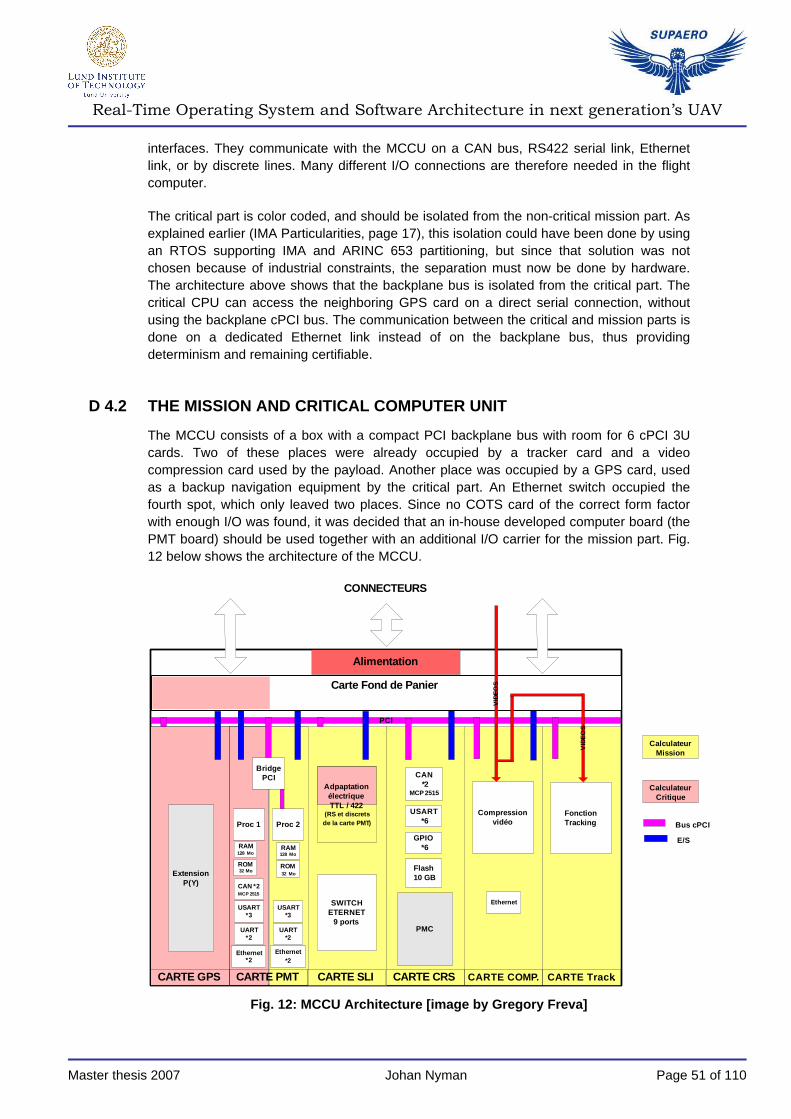
Real-Time Operating System and Software Architecture in next generation’s UAV
Master thesis 2007 Johan Nyman Page 51 of 110
interfaces. They communicate with the MCCU on a CAN bus, RS422 serial link, Ethernet link, or by discrete lines. Many different I/O connections are therefore needed in the flight computer.
The critical part is color coded, and should be isolated from the non-critical mission part. As explained earlier (IMA Particularities, page 17), this isolation could have been done by using an RTOS supporting IMA and ARINC 653 partitioning, but since that solution was not chosen because of industrial constraints, the separation must now be done by hardware. The architecture above shows that the backplane bus is isolated from the critical part. The critical CPU can access the neighboring GPS card on a direct serial connection, without using the backplane cPCI bus. The communication between the critical and mission parts is done on a dedicated Ethernet link instead of on the backplane bus, thus providing determinism and remaining certifiable.
D 4.2 THE MISSION AND CRITICAL COMPUTER UNIT
The MCCU consists of a box with a compact PCI backplane bus with room for 6 cPCI 3U cards. Two of these places were already occupied by a tracker card and a video compression card used by the payload. Another place was occupied by a GPS card, used as a backup navigation equipment by the critical part. An Ethernet switch occupied the fourth spot, which only leaved two places. Since no COTS card of the correct form factor with enough I/O was found, it was decided that an in-house developed computer board (the PMT board) should be used together with an additional I/O carrier for the mission part. Fig. 12 below shows the architecture of the MCCU.
Calculateur Mission
Proc 1 Proc 2
Extension P(Y)
CARTE PMTCARTE GPS CARTE CRS CARTE COMP. CARTE Track.
CAN *2
MCP 2515
PCI
CONNECTEURS
Bridge PCI
CAN *2MCP 2515
USART *3
UART *2
USART *3
UART *2
GPIO *6
PMC
Ethernet *2
Ethernet *2
RAM 128 Mo
ROM 32 Mo
RAM128 Mo
ROM 32 Mo
Alimentation
Ethernet
Compression vidéo
Fonction Tracking
Calculateur Critique
Carte Fond de Panier
Adpaptation électrique TTL / 422
(RS et discrets de la carte PMT)
SWITCH ETERNET
9 ports
CARTE SLI
VID
EO
S
VID
EO
S
Flash 10 GB
Bus cPCI
E/S
USART *6
Fig. 12: MCCU Architecture [image by Gregory Freva]

Real-Time Operating System and Software Architecture in next generation’s UAV
Master thesis 2007 Johan Nyman Page 52 of 110
Only the mission part can access the backplane bus and the supplementary I/O card. The PMT card has enough I/O for the critical part.
D 4.3 THE PMT BOARD
This board has two separated processors, each with their own I/O. By using one processor to host the critical code, and the other to host the mission part of the software, hardware separation can theoretically still be maintained. Fig. 13 below shows the architecture of the PMT card.
PROCESSEURPQII
(HOST)
PROCESSEURPQII
(AGENT)
INTERFACEUNIVERSELLE
PCI / PCI32bits
MEMOIRESDRAM
MEMOIREFLASH
cPCI
64 16
MEMOIRESDRAM
MEMOIREFLASH
64 16
physical layer
FCC1
physical layer
FCC2
RJ4510/100
SCC1 SCC3 SCC4
SMC1
SMC2RS232
CONN
ECT
EU
RC
OM
PAC
T PC
I (J1
+J2)
CONNECTEUR J2 micro SUBD9 CONN. J2
physical layer
FCC1
physical layer
FCC2
SCC1 SCC3 SCC4
SMC1
SMC2RS232
CONNECTEUR J2 micro SUBD9 CONN. J2
JTAG
JTAG
bus CAN
buffers drivers
IOs
MEMOIRE EEPROM
SERIE
JTAG secondary port
primaryport
local PCI
SPISPI
LOGIQUECABLÉE
8
bus 60x
LOGIQUECABLÉE
8
bus 60x
vers servitudes des composants de la carte
vers servitudes des composants de la carte
port A [8..31], port B [18..31], port C [0..1,4..29] , port D[7,14..25,29..31]
port A [8..31], port B [18..31], port C [0..1,4..29] , port D[7,14..25,29..31]
sonde de t°
buffer SMBus
CONN. J1
I2 C
Fig. 13: The PMT computer board architecture [image from within the company]
The board holds two PowerQUICK II microcontrollers, with a PowerPC 603 core. Each processor has 128 MB of SDRAM and 32 MB of Flash memory. Resources on the board includes:
– 4 Ethernet ports (2 per processor)
– 10 serial connections RS 232 and/or RS422 (5 per processor)
– 8 general configurable I/O lines (4 per processor) that interconnect directly with the processor interrupt controller.
– 1 CAN bus controller to be used only by the critical part. (One redundant controller will be added)
– 1 I2C bus
– 1 PCI bus controller which connects the processors and the bridge to the backplane compact PCI bus
D 5 SOFTWARE ARCHITECTURE
The functional specification seen in chapter D 3 above must be translated into a real-time architecture, using structures available by the operating system, such as tasks,
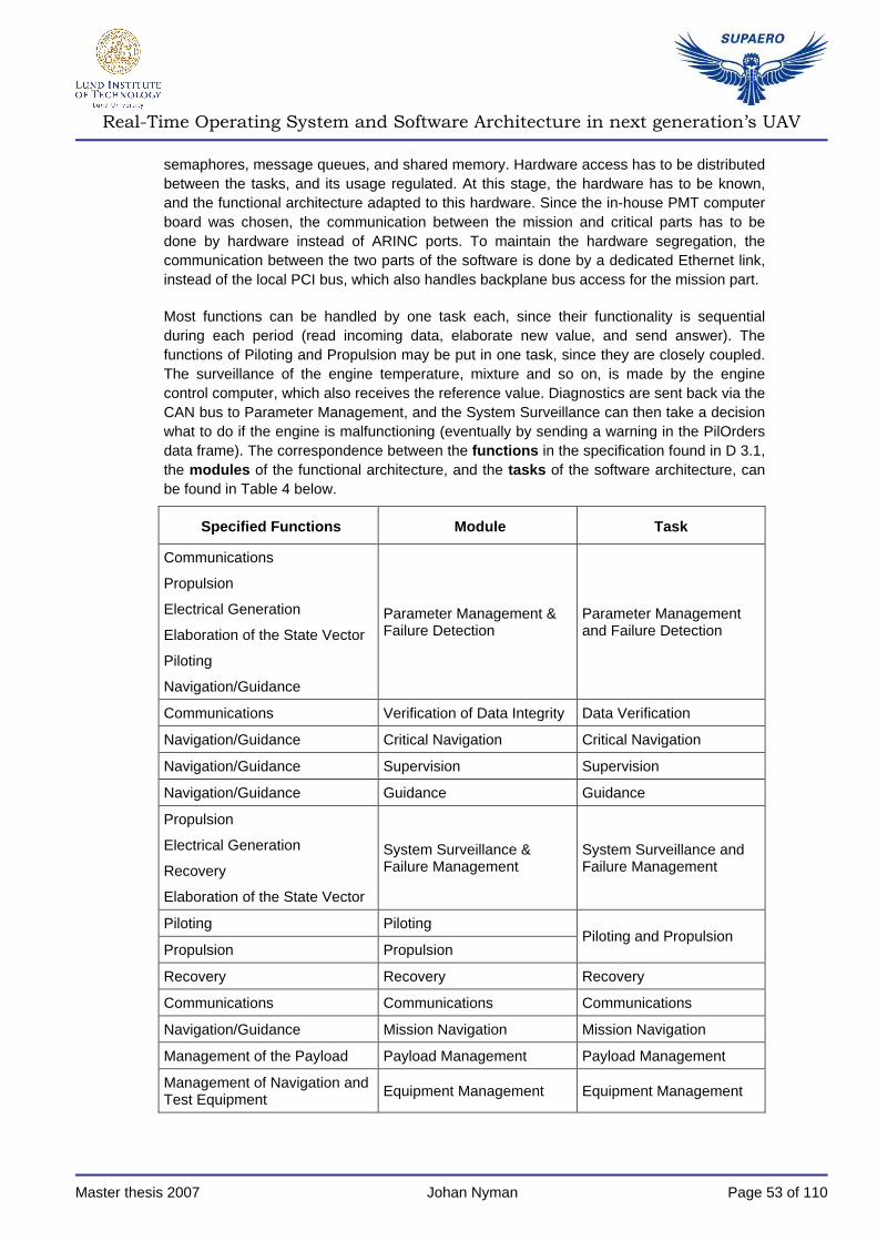
Real-Time Operating System and Software Architecture in next generation’s UAV
Master thesis 2007 Johan Nyman Page 53 of 110
semaphores, message queues, and shared memory. Hardware access has to be distributed between the tasks, and its usage regulated. At this stage, the hardware has to be known, and the functional architecture adapted to this hardware. Since the in-house PMT computer board was chosen, the communication between the mission and critical parts has to be done by hardware instead of ARINC ports. To maintain the hardware segregation, the communication between the two parts of the software is done by a dedicated Ethernet link, instead of the local PCI bus, which also handles backplane bus access for the mission part.
Most functions can be handled by one task each, since their functionality is sequential during each period (read incoming data, elaborate new value, and send answer). The functions of Piloting and Propulsion may be put in one task, since they are closely coupled. The surveillance of the engine temperature, mixture and so on, is made by the engine control computer, which also receives the reference value. Diagnostics are sent back via the CAN bus to Parameter Management, and the System Surveillance can then take a decision what to do if the engine is malfunctioning (eventually by sending a warning in the PilOrders data frame). The correspondence between the functions in the specification found in D 3.1, the modules of the functional architecture, and the tasks of the software architecture, can be found in Table 4 below.
Specified Functions Module Task
Communications
Propulsion
Electrical Generation
Elaboration of the State Vector
Piloting
Navigation/Guidance
Parameter Management & Failure Detection
Parameter Management and Failure Detection
Communications Verification of Data Integrity Data Verification
Navigation/Guidance Critical Navigation Critical Navigation
Navigation/Guidance Supervision Supervision
Navigation/Guidance Guidance Guidance
Propulsion
Electrical Generation
Recovery
Elaboration of the State Vector
System Surveillance & Failure Management
System Surveillance and Failure Management
Piloting Piloting
Propulsion Propulsion Piloting and Propulsion
Recovery Recovery Recovery
Communications Communications Communications
Navigation/Guidance Mission Navigation Mission Navigation
Management of the Payload Payload Management Payload Management
Management of Navigation and Test Equipment
Equipment Management Equipment Management

Real-Time Operating System and Software Architecture in next generation’s UAV
Master thesis 2007 Johan Nyman Page 54 of 110
Specified Functions Module Task
Maintenance and Test Maintenance Maintenance
Table 4: Correspondence between specified functions , modules in the functional architecture and tasks in the software architecture
Appendix A gives a more detailed description of each task. A lot of data is sent between the tasks. In ARINC terminology, buffers and blackboards are used for intra-partition communications, while the corresponding POSIX and VxWorks terminology corresponds to message queues and (semaphore protected) shared memory respectively. The ARINC terminology uses queuing ports and sampling ports for similar means of communication between partitions. This does not exist for the POSIX or VxWorks API. In the task descriptions in appendix A, data frame names are centered on content, so is the media used for transmission.
D 5.1 ARINC IMPLEMENTATION WITH LYNXOS-178
An implementation of the software architecture has been made using the ARINC 653 API and LynxOS-178 on a PC-board with a single x86 processor. This skeleton implements all communication between tasks, but not the actual function algorithms. Isolation is maintained by using different ARINC partitions. The architecture can be seen in Fig. 14 below. The processes beginning with “env” are the initialization processes for each partition, which set up the all the communication means, the processes, and then starts them. Since hardware cannot be accessed from a partition using the ARINC API, another partition should be created where all I/O access is concentrated. This partition, which is neither implemented, nor visible in the image below, sends its data to the Sd_Measures sampling port, and receives the reference outputs on the Ss_PilCommands port. This partition must be developed to the same assurance level as the critical partition.

Real-Time Operating System and Software Architecture in next generation’s UAV
Master thesis 2007 Johan Nyman Page 55 of 110
env0
DataVerification
ParamMgmt
Recovery
Receiver
bb_Params
bu_ParamOrders
bu_Orders
env1
PLMgmt
Communication
env2
MissNav
bb_CritNavOrders
Supervision
CritNav
0
”Qd_Com0"id_in_Com
0
”Ss_Params"id_out_Params
1
”Sd_Measures"id_in_Measures
3
”Ss_MissNavOrders"id_out_MissNavOrders
bb_CritNavInfo
bb_GuidOrders
bb_GCSPilOrders
1 ”Qd_Video"id_in_Video
PilProp
SySFaM
Guidance
bb_GuidInfo
bb_PilOrders
2
”Ss_PilCommands"id_out_PilCommands
4
”Sd_MissNavInfo"id_in_MissNavInfo
4 ”Ss_MissNavInfo"id_out_MissNavInfo
”Qs_Video"id_out_Video 1
”Sd_MissNavOrders"id_in_MissNavOrders 3
0
”Qs_Com"id_out_Com
0
”Sd_Params1"id_in_Params
0
”Sd_Params2"id_in_Params
5”Sd_PL"id_in_PL
2”Qd_PLControl"id_in_PLControl
5”Ss_PL"
id_out_PL
0
”Qd_Com2"id_in_Com
Maintenance
Eqpt Mgmt
”Qs_PLControl"id_out_PLControl2
Fig. 14: ARINC 653 structures for the proposed soft ware architecture
All communication between the critical and mission partition uses ARINC ports in the implementation and the figure above. The prefixes for the ARINC ports have the following meanings:
– Qs Queuing port, source
– Qd Queuing port, destination
– Ss Sampling port, source

Real-Time Operating System and Software Architecture in next generation’s UAV
Master thesis 2007 Johan Nyman Page 56 of 110
– Sd Sampling port, destination
Ports with the same index number and type (queuing or sampling) communicate.
D 5.2 VXWORKS IMPLEMENTATION
The following sketch (Fig. 15) shows the real-time architecture for the critical part, implemented for the VxWorks API on the PMT computer board. Compared to the ARINC implementation, hardware access is now direct, and no ports are used. No good correspondence to blackboards was found for inter-task communication, so a global structure containing the structure to be sent and a protecting semaphore was created.
memory
buffered I /O
shared memory
message queue
semaphore protected shared memory
mutex semaphore
binary semaphore
Supervision
System Surveillance and
Failure Management
Guidance
Parameter Management and Failure Detection
Piloting and propulsion
Critical Navigation
DataVerification
ROS
Begin recovery
CAN
CAN mutex
SerialEthernet
Mission mutex
Recovery
Discrete I/O
sd_CritNavOrders
sd_PilOrders
sd_GCSPilOrders
sd_GuidInfo
sd_GuidOrders
sd_CritNavInfo
sd_Params
mq_ParamOrders
mq_Orders
Fig. 15: VxWorks real-time architecture of critical part
No periodic tasks can be declared by the VxWorks API. Therefore, every periodic task has to contain a loop, with a call to sleep every period. The sleep-time should be equal to the task’s period minus its execution time (including the time it is waiting for higher priority tasks to run). The periodic tasks all follow the principle shown beneath:
int periods = 0; start_time = getCurrentSystemTime(); while (ALL_OK) { perform algorithm periods++;
stop_time = getCurrentSystemTime(); sleep(start_time+periods*TASK_PERIOD – stop_time);
} /*end while, return to wait for semaphore*/

Real-Time Operating System and Software Architecture in next generation’s UAV
Master thesis 2007 Johan Nyman Page 57 of 110
The execution time for each algorithm must of course be less than the task’s own period, but it must also allow other higher priority tasks to execute during this period. If the task is pre-empted during the calculation of the time, the sleep time might be a little bit too short or too long, but since it is re-adjusted every period there will be no drift or integrated error.
D 6 CERTIFICATION IMPACT ON THE SOFTWARE ARCHITECTURE
The airworthiness certification imposes quite a lot of constraints, not only on the software development cycle, but more on the system as a whole. In fact, developing the software following the guidelines in DO-178B is the easy part. The software is just a small part of the system, even though it controls all the rest. The fact that it interacts with every sensor and actuator onboard is perpetrating.
Certification level of a software function is determined by the safety analysis of the whole system, and the impact of an error in the considered function [R7]. The software implementing the function has to be developed to the level of criticality of that function, unless a segregated mean exists for surveillance or redundancy of the behavior. This can be for example a physical differentiation and control, or voting between several redundant sensors or function outputs.
When several functions are sharing resources, all those functions have to be certified to the highest level of those functions implicated [R1]. Partitioning of the software permits to separate the functions of higher criticality from those with lower criticality, and thus avoiding developing all to the highest level [R7]. Partitions of different criticality can thus share the same computer and resources [R5].
“The software certification level for each partition may be determined by the most severe failure condition associated to a software component in that partition.” [R1 §2.3.1]. My interpretation of this is the following:
– The piloting module, which keeps the plane in the air, has the highest level since the plane may crash and cause potential damage/injury if it fails. All other modules in the same partition must be developed to the same certification level.
– The navigation module, if put in another partition, cannot crash the plane, only make it go to the wrong place if erroneous. It may therefore be developed to a lower level, and still communicate with the piloting module, if this communication is not harmful for the piloting module (i.e. make it stall, take a turn too steep, fly into ground). To avoid the case of following a trajectory which leads into ground, a low altitude protection function, developed at the same level of safety as the piloting module, can be used. The navigation module can then be permitted to have a lower safety level in a separate partition.
But considering a software function alone is not enough. Conformance with DO-178B of the flight control software (which keeps the plane flying) is not enough if the inputs to this function are not reliable to the same level, and assuring that the commands are executed by the actuators. This means that the whole chain “from sensor to processing to actuator” has to be developed to the same degree of criticality. In the example with the flight controls, input comes from inertial sensors, accelerometers and higher order commands from

Real-Time Operating System and Software Architecture in next generation’s UAV
Master thesis 2007 Johan Nyman Page 58 of 110
navigating software or ground control station. Output goes to the control surfaces via electrical or hydraulic actuators. Data is transferred on a data bus, which also has to be certified to the highest level of criticality of the data that circulates on the bus. Once we’re sure that the integrity of the data is correct by using a conformant bus and partitioned software, the question is whether its value is correct. If the elaboration of the value at its source is not developed to the same level of criticality, there has to be a “safe” way of controlling its validity. This can be done for example by using dissimilar software , which means having two or more functions, developed by different teams in a different way, elaborating the same value and then controlling their consistency. Another way is to have a segregated chain of surveillance , with different sensors and actuators, surveying simple criteria (thus reliable) and capable of avoiding a catastrophic failure in case of an error in the input to the flight commands. In the case of the new UAV this can be for example a radio altimeter, which triggers a recovery in case of low altitude. This will render an error in navigation harmless, since it will be impossible to fly into ground without having the recovery triggered by the surveillance.
In the case of the new UAV, the certification process imposes the following constraints:
– The ground station has to be certified to the same level as the aircraft, since it can directly control the vehicle,
– Sensors and actuators have to be conformant with the same criticality level as the function that uses or elaborates the value. Otherwise they have to be redundant. For example, the software in the HNS which determines the aircrafts attitude, gives direct input to the piloting function (flight commands) and must therefore be developed to the same criticality level,
– The plane has to be equipped with a certified radio-altimeter for surveillance (to avoid certifying ALL the software). If this is in a separate system, it could trigger a recovery in case of danger, thus avoiding the certification of the ground control station.
If certification is not necessary today there are a few steps to take in order to make the UAV certifiable later on without re-making the whole system. (USAR certification implies DO-178B level C [R17])
– Use of an RTOS supporting partitioning, (and the IMA aspect),
– Separation of the “need for certification”-software from the “less critical”-software in different partitions,
– A modular software architecture.
While the separation of different criticalities can be done in hardware instead of using a RTOS supporting partitioning, the use of the latter has several advantages. Communication between the functions is handled by the OS, while in the case of hardware segregation it is the programmer who deals with the communication on the bus between the processors and has to make sure this is handled correctly. If the data bus is shared with other partitions, the hardware segregation is lost, but an OS support ing ARINC 653 can make sure that fault isolation is maintained.

Real-Time Operating System and Software Architecture in next generation’s UAV
Master thesis 2007 Johan Nyman Page 59 of 110
D 7 PORTING OF SOFTWARE FROM THE EXISTING UAV TO THE NEW UAV
A direct porting of the code from the existing UAV to the new UAV is probably the fastest and cheapest way to get a working prototype. It is however, neither a good solution, nor economic in a longer perspective, due to the points seen in “Feedback from the existing UAV”, page 46, especially considering software maintenance and future evolutions.
Without any considerations to the new software architecture, the task of porting the code from the existing UAV to the flight computer in the new UAV is affected by the following facts:
D 7.1 DIFFERENT AVIONICS ARCHITECTURE
D 7.1.1 Separation
A bi-processor computer board will be used in the new UAV. The two microcontrollers could then replace the processor and I/O on each board in the existing UAV’s MCU. Instead of a VME bus, they are interconnected by a dedicated Ethernet link, and communicate with other cards on the backplane compact PCI bus. The best thing would be to assign the PGU to one microcontroller, and the IOU to the other. Considering performance of the microprocessors, this should not be a problem, since the MPC8247 is around 100 times more powerful than the current MC68040 and MC68360. The new avionics architecture however, has one critical part and one mission part. This separation is less strict in the software of the existing UAV, and this makes the hardware separation in the computer of the new UAV meaningless.
D 7.1.2 Input/Output
Another thing to consider is the question of connected I/O. On the PMT board each microcontroller has half of the I/O on the board. If the IOU uses more than that, it has to be split on the two processors as well. Another I/O board will also be added to the flight computer, and since the separation between mission and flight control is less distinct in the existing software, both the PGU and the IOU needs to access this card, instead of just the mission unit of the proposed software architecture for the new UAV.
D 7.1.3 Drivers
Since new hardware is used, the software layer, which interfaces directly with the material, has to be changed. Normally, drivers are supplied by the OS vendor, but in the existing software, there are still parts which interact directly with the hardware or access drivers. These parts have to be rewritten.
D 7.2 DIFFERENT SENSORS/ACTUATORS
By using “smart actuators” on bus, the innermost control loop which surveys actuator position is no longer needed. This part has to be deleted, and replaced by an interface to the bus. Considering sensors, there will no longer be any analog inputs, but serial, one-bit

Real-Time Operating System and Software Architecture in next generation’s UAV
Master thesis 2007 Johan Nyman Page 60 of 110
digital or bus input. This part has to be redeveloped. Input and output is simplified by using an OS with drivers for these peripherals.
D 7.3 DIFFERENT TRANSMISSIONS
The transmissions will change in the new UAV, making the “Transmission Management” module from the existing UAV obsolete. This part, which directly handles the antennas, will be taken over by a dedicated transmission computer. A new interface will therefore have to be developed.
D 7.4 DIFFERENT OS
In the existing UAV, the interaction with the OS is minimal, which raises the question why an OS is needed if the code is ported to the new UAV. But as seen above, the solution to many of the porting problems, and many of the problems with the existing UAV's software, is to use features of the OS.
D 8 THE PROTOTYPE FLIGHT COMPUTER
The original plan to implement a skeleton of the software architecture on the actual hardware chosen for the MCCU, should demonstrate the feasibility, detect bottlenecks in the development, and address issues of certification. This has all been done. Work is continuing at the company to perform further tests and implement the full software for the flight computer.

Real-Time Operating System and Software Architecture in next generation’s UAV
Master thesis 2007 Johan Nyman Page 61 of 110
PART E: CONCLUSIONS AND FUTURE WORK
The goals for this internship were the following:
– Find the most suitable RTOS for use in the new UAV
– Propose a modular certifiable software architecture
– Develop a prototype flight computer and test the chosen RTOS and the software architecture.
Different criteria of choice for the RTOS to use in the new UAV were defined and ranked. An evaluation of facts was followed by a practical user evaluation where LynxOS-178 was tested on an x86/PC computer board, and VxWorks 6.3 on a PMT computer board. A comparison between the two, following the criteria of choice, showed that LynxOS-178 was the better one regarding certification aspects, while VxWorks had a better development environment and is more user-friendly. However, the choice of RTOS was directed by industrial constraints and the choice of hardware. In order to be compatible with COTS equipment with many different kinds of I/O, and to reduce hardware cost, the PMT computer board was chosen. Since a BSP for VxWorks 6.3 already exists and is in use within the company, together with the fact that the certification constraint was dropped, this OS was chosen.
A modular software architecture, which does not inhibit an eventual certification, has been proposed and partly implemented. From a description of the UAV’s different functionalities, feedback from the software team, and input from the system engineering team, the different functions and their interactions were defined. The software was split in one critical part, and one mission part, with everything needed to keep the aircraft flying safely placed in the critical part. The functions and their interfaces were then further specified.
A flight computer prototype has been developed using the PMT card, VxWorks 6.3 and a functional skeleton implementation of the software architecture. Work on the prototype continues within the company. Some issues regarding certification, detected during this internship, have to be resolved, and the hardware architecture may still evolve. The work with the prototype so far has highlighted the following points:
� The first software implementation, made for the ARINC653 API using LynxOS-178 and a single-processor computer board, has shown that the abovementioned API is very easy to use, and suits the application perfectly. Furthermore, ARINC 653 partitioning is very advantageous from the programmer’s point of view, but the issue of addressing hardware has to be solved.
� On the other hand, using VxWorks 6.3 on the PMT board without ARINC partitioning, hardware access can be done directly by the application, but the communication between the critical and mission part (on different processors) has to be implemented in a “safe” way.
� By using a subset of the VxWorks API when implementing this software, the application and the operating system remains conformant with DO-178B. A certifiable BSP has to be redeveloped though.
Regarding airworthiness certification and communication between independent functions of different criticalities, it has been seen that a function of higher criticality can send data and
Real-Time Operating System and Software Architecture in next generation’s UAV
Master thesis 2007 Johan Nyman Page 62 of 110
orders to a function of lower criticality without violating any certification rules, but the other way is different. When a function of lower criticality provides information to a function of higher criticality, this data has to be checked in some way, or else a segregated mean for surveillance has to be provided. By having a surveillance chain that can avoid a fai lure of the higher criticality level, the communication from a lower level of criticality to a higher level can be allowed. This rule applies regardless if the isolation between different criticalities is made by hardware or by an RTOS providing ARINC partitioning.
The hardware choice for the new UAV provides segregated hardware to separate the functions of different criticalities, instead of using an OS providing partitioning. The communication between the processors, the backplane bus, and common components on the card has to be further examined, to ensure that the segregation is maintained when accessed by functions of different criticalities. This is future work.
This thesis work has been very interesting, in part because of the subject, but also because of the freedom of choice that has been left to me. I have learnt a lot about avionics software and hardware, industrial constraints, the certification process, and the engineering practice.
I have seen first-hand the interactions between hardware and software; how software choices have impact on the choice of hardware architecture, and reciprocally, the choice of hardware constrains the software architecture and choice of RTOS. The most important conclusion that I draw from this study is that when trying to obtain the most economic solution and at the same time airworthiness certifi cation, the system as a whole must be considered, and the choice of hardware and softw are must be done together.
My biggest satisfaction however, is that the material produced during this internship will be used in the ongoing development of the new UAV.

Real-Time Operating System and Software Architecture in next generation’s UAV
Master thesis 2007 Johan Nyman Page 63 of 110
PART F: BIBLIOGRAPHY
APPLICABLE DOCUMENTS
[A1] Confidential
[A2] Confidential
REFERENCE DOCUMENTS
[R1] EUROCAE: ED-12B: Considérations sur le logiciel en vue de la certification des systèmes et équipements de bord, édition 2, December 1992. Identical with RTCA DO-178B.
[R2] RATC DO-248B / EUROCAE ED-94B. Clarification of DO-178B, in particular, discussion of partitioning aspects in appendix D, section 14.
[R3] ARINC: ARINC Specification 653: Avionics Application Software Standard Interface, draft 4, August 25 2005.
[R4] J Rushby: Partitioning in Avionics Architectures: Requirements, Mechanisms, and Assurance, March 2000, document number: DOT/FAA/AR-99/58 or NASA/CR-1999-209347: Discussion of what is required in order to achieve the same isolation and fault containment in IMA as in a federated architecture.
[R5] ARINC: ARINC Report 651-1: Design Guidance for Integrated Modular Avionics, November 7, 1997.
[R6] C. Gouley: Les Systèmes de Traitement de l’Information embarqués pour l’aéronautique civile, Cours à SUPAERO Systèmes Informatiques Embarqués 2006/2007. About different architectures (federated, IMA) and data buses. Examples of avionics architectures: B777, A320, 330, 340 380, Mirage 2000 etc.
[R7] SAE: ARP4754: Certification Considerations for Highly-Integrated of Complex Aircraft Systems
[R8] ARINC: ARINC Specification 659: Backplane Data Bus
[R9] ARINC: ARINC Specification 629: Multi-transmitter Data Bus
[R10] ARINC: ARINC Specification 650: Integrated Modular Avionics Packaging and Interfaces
[R11] ARINC: ARINC Specification 664 Part 7: Aircraft Data Network Part 7: Avionics Full Duplex Switched Ethernet (AFDX) Networks

Real-Time Operating System and Software Architecture in next generation’s UAV
Master thesis 2007 Johan Nyman Page 64 of 110
[R12] ARINC: ARINC Report 613: Guidance for using the ADA programming language in avionic systems
[R13] SDD_pgu_rev7: Document de conception du logiciel PGU du MCU dans le cadre des drones SPERWER, SPERWER-LE et MOYEN DUC
[R14] M. Barr: How to Choose a Real-Time Operating System, CMP Media 2003
[R15] M. Hedlund, F. Aronson: Evaluation of real-time operating systems for safety-critical systems, School of Engineering at Jönköping University, 2002
[R16] M. A. Dornheim: Isolating Safety, Aviation Week and Space Technology, July 11 2005
[R17] UAV Systems Airworthiness Requirements (USAR) - Référentiel de navigabilité des systèmes de drones, Paragraphe USAR v3.0 AMC 1309(b) 6a. This norm recently evolved into STANAG 4761.
[R18] P. Melanson, F. Tafazoli: A selection methodology for the RTOS market, presented at Data Systems in Aerospace (DASIA 2003) conference, June 4th 2003, Prague, Czech Republic.
[R19] Wayne Wolf: Computers as Components – Principles of Embedded Computing System Design, 2001, Morgan Kaufman Publishers, ISBN 1-55860-693-9
[R20] J.A Carbone, RTOS Real-Time Performance vs. Ease Of Use, Express Logic, http://www.rtos.com/page/imgpage.php?id=208, accessed in may 2007
[R21] J. Turley: Operating Systems on the Rise. http://www.embedded.com/showArticle.jhtml?articleID=187203732, accessed in may 2007. Data from Embedded Systems Programming 2006 Survey,
[R22] Wind River (VxWorks) website: http://www.windriver.com, accessed during April – September 2007
[R23] LynuxWorks (LynxOS) website: http://www.lynuxworks.com, accessed during April – July 2007
[R24] Green Hill Software (INTEGRITY) website: http://www.ghs.com, accessed during April – June 2007
[R25] CsLEOS website: http://www.csleos.com, accessed during April 2007
[R26] Micrium OS-II website: http://www.micrium.com/, accessed during April – May 2007
[R27] SK-0000065577 OS DMS Presentation (powerpoint)
[R28] SK-0000065599 CR – 11/06/2007 – Présentation du Scheduler DMS de l’URD18
[R29] M. E. Anderson: Selecting the Right RTOS, A Comparative Study, Embedded Systems Conference, March 2002

Real-Time Operating System and Software Architecture in next generation’s UAV
Master thesis 2007 Johan Nyman Page 65 of 110
[R30] SK0000066795-01 Compte Rendu de Seminaire Wind River AeroSpace and Defence 14 juin 2007
[R31] Wind River General Purpose Platform, VxWorks Edition, Getting Started, 3.3
[R32] WindRiver Workbench User’s Guide 2.5, VxWorks Version
[R33] WindRiver MemScope User’s Guide
[R34] WindRiver ProfileScope User’s Guide
[R35] Note URD09/NI/07/0185: Manuel Utilisateur pour le développement du logiciel
[R36] Note URD09/NI/07/0002-01: EOMS VAMPIR NG Problèmes des transferts PCI pour le traitement IRST.
[R37] WindRiver: VxWorks 6 Certification Profile
[R38] LynxOS-178 Installation manual
[R39] LynxOS-178 User’s Guide
[R40] Krzysztof M. Sacha: Measuring the Real-Time Operating System Performance, Institute of Control and Computation Engineering, Warsaw University of Technology
[R41] F. Persson: Multi-project methods for organizations implementing agile software development, Lund Institute of Technology
[R42] L Beus-Dukic: Criteria for Selection of a COTS Real-Time Operating System: a Survey, School of Computing and Mathematics, University of Northumbria at Newcastle

Real-Time Operating System and Software Architecture in next generation’s UAV
Master thesis 2007 Johan Nyman Page 66 of 110
PART G: APPENDIX A – TASK SPECIFICATION
This appendix describes the tasks used in the software architecture depicted by Fig. 14 and Fig. 15.
G 1 PARAMETER MANAGEMENT AND FAILURE DETECTION
This task collects all data concerning the aircraft and its environment needed by other tasks. It makes a first processing of the data, for example to see if two redundant sensors give the same data. It then provides the information in one structure: Parameters. This structure contains the State Vector. The reason to have one task doing all the data collection is to avoid having several tasks, in need of the same measurements, making the same samples several times during the same cycle. Only this task can write in the shared memory containing the Parameters, while all others can read it. ARINC 653 does not use shared memory object, so a blackboard should be used instead. The messages are copied from the sending task to the blackboard and then to the receiving task. If the messages are big, this might not be the best way to do it. The alternative would be to select which parts of the parameters to send to each respective task. Given that we have much memory and processing power, the first alternative is a lot easier from the developer’s point of view, and the task remains independent of the surrounding tasks. The algorithm for selecting which parts to send might take longer than just copying the whole message, and it would have to be re-specified each time a new function is added to the software structure.
Equipment-specific acquisitions needed in non-critical partitions are performed by the tasks in need of the measurements, for example Payload Management and Equipment Management.
G 1.1 PHYSICAL RESOURCES:
– Various sensors onboard,
– GPS, HNS, ADU,
– Ethernet connection to mission part,
– CAN bus

Real-Time Operating System and Software Architecture in next generation’s UAV
Master thesis 2007 Johan Nyman Page 67 of 110
G 1.2 INPUT/OUTPUT:
Input From Frame ARINC 653 media
VxWorks media
Mode set (ex: lost com.)
Verification of Integrity
[ParamOrders] [bu_ParamOrders] [mq_ParamOrders]
Orders from communications via Data Verification (ex: recover)
Data Verification [ParamOrders] [bu_ParamOrders] [mq_ParamOrders]
Data from surrounding equipment (sensors)
Hardware [Measures] [Sd_Measures] Serial
CAN
Output To
Current Parameters All critical tasks [Params] [bb_Params] [sd_Params]
Current Parameters All mission tasks [Params] [Ss_Params] Ethernet Table 5: Input and Output of the Parameter Managemen t and Failure Detection task
G 1.3 HIGH LEVEL ALGORITHM:
– Collect data from connected equipment (on CAN, serial, and GPIO)
– Check for errors and inconsistency
– Check ParamOrders buffer
– If (order received or mode set)
� Set corresponding mode / phase in State Vector
– Update Parameters accordingly
G 2 DATA VERIFICATION
This task receives orders from the Ground Control Station (GCS), via the communication module. It acts like a receiver task in the critical part, which checks the consistency of the incoming GCS data frame and then dispatches the frame to the correct function.
G 2.1 PHYSICAL RESOURCES:
– Ethernet connection to mission part

Real-Time Operating System and Software Architecture in next generation’s UAV
Master thesis 2007 Johan Nyman Page 68 of 110
G 2.2 INPUT/OUTPUT:
Input From Frame ARINC 653 media VxWorks media
Data frame Communication [Communication] [Qd_Com0] Ethernet
Output To
Verified Data frame Supervision [Communication] [bu_Orders] [mq_Orders]
Navigation orders Mission Navigation
[NavOrders] [Ss_MissNavOrders] Ethernet
Navigation orders Critical Navigation
[NavOrders] [bb_CritNavOrders] [sd_CritNavOrders]
Error message / mode change
Parameter Management
[Communication] [bu_ParamOrders] [mq_ParamOrders]
Table 6: Input and Output of the Data Verification t ask
G 2.3 HIGH LEVEL ALGORITHM:
– Read incoming data frame from Communication
– Verify consistency (integrity)
– Reset watchdog
– Dispatch data frame (to Navigation, Supervision, Parameter Management)
– Timer watchdog allows to detect lost communication
– If (com lost or data not consistent)
� Send new order to Parameter Management (tell to use ROS)
G 3 CRITICAL NAVIGATION
This task elaborates high-level commands during critical phases of flight (take-off, recovery, and ROS). In normal flight it keeps track of the next ROS waypoint, and elaborates high-level commands to go there. Should a failure occur with the UAV or the Mission Navigation, Supervision uses these commands for Guidance.
G 3.1 INPUT/OUTPUT:
Input From Frame ARINC 653 media VxWorks media
ROS Flight Plan (waypoints)
Memory
Current position State vector [Params] [bb_Params] [sd_Params]
Navigational orders from GCS
Data Verification [NavOrders] [bb_CritNavOrders] [sd_CritNavOrders]
Output To
High-level commands (Heading, Speed, Altitude)
Supervision [NavInfo] [bb_CritNavInfo] [sd_CritNavInfo]
Table 7: Input and Output of the Critical Navigatio n task

Real-Time Operating System and Software Architecture in next generation’s UAV
Master thesis 2007 Johan Nyman Page 69 of 110
G 3.2 HIGH LEVEL ALGORITHM:
– Get parameters
– Check for new navigational orders
– If new ROS received, add to ROS Flight Plan
– Elaborate high-level commands
� During critical phases (Take-Off, Recovery, ...)
� Or from position to next ROS waypoint in normal flight
– Send to Guidance (via Supervision)
G 4 SUPERVISION
This task works as a switch between the different navigation functions. Depending on the flight phase and the status of the UAV, it can use either Mission or Critical Navigation and send their information to the Guidance module. Incoming data from Mission Navigation is checked for consistency. To the navigation information, it adds margins for the Guidance module to stay within. The Supervision task can also receive high-level orders from the Ground Control Station, via Data Verification, or low-level orders the same way, which it passes on to the Guidance or System Surveillance task. From the ground control station it can also receive a manual recovery order, which it sends on to System Surveillance.
G 4.1 PHYSICAL RESOURCE:
– Ethernet connection to mission part
G 4.2 INPUT/OUTPUT:
Input From Frame ARINC 653 media VxWorks media
High-level commands Mission Navigation
[NavInfo] [Sd_MissNavInfo] Ethernet
High-level commands Critical Navigation
[NavInfo] [bb_CritNavInfo] [sd_CritNavInfo]
Verified data frame (may contain high-level or low-level commands from GCS)
Data Verification
[Communication] [bu_Orders] [mq_Orders]
Output To
High-level commands (Heading, Speed, Altitude)
Guidance [GuidOrder] [bb_GuidOrder] [sd_GuidOrder]
Low-level commands from GCS (Pitch, Roll, Yaw, Throttle)
System Surveillance
[GuidInfo] [bb_GCSPilOrder] [sd_GCSPilOrder]
Table 8: Input and Output of the Supervision task

Real-Time Operating System and Software Architecture in next generation’s UAV
Master thesis 2007 Johan Nyman Page 70 of 110
G 4.3 HIGH LEVEL ALGORITHM:
– Read incoming data frame(s)
– Check consistency of Mission Navigation information
– Choose accordingly to send
� high-level commands from Mission Navigation and margins to Guidance
� high-level commands from Critical Navigation and margins to Guidance
� high-level commands from GCS and margins to Guidance
� low-level commands from GCS (and eventually margins) to System Surveillance
G 5 GUIDANCE
The Guidance task takes high-level commands such as heading, speed and altitude, and transforms them into low level commands (attitude of the aircraft).
G 5.1 INPUT/OUTPUT:
Input From Frame ARINC 653 media VxWorks media
High-level commands and margins (reference values of Heading, Speed and Altitude)
Supervision [GuidOrders] [bb_GuidOrders] [sd_GuidOrders]
Current Heading, Speed and Altitude
Parameter Management
[Params] [bb_Params] [sd_Params]
Output To
Low-level commands (Pitch, Roll, Yaw, Throttle)
System Surveillance
[GuidInfo] [bb_GuidInfo] [sd_GuidInfo]
Table 9: Input and Output of the Guidance task
G 5.2 HIGH LEVEL ALGORITHM:
– Get parameters
– Get high level commands from Supervision
– Elaborate Pitch, Roll, Yaw and Thrust reference from current and reference Heading, Speed and Altitude
– Send to Piloting (via System Surveillance and Failure Management)
G 6 SYSTEM SURVEILLANCE AND FAILURE MANAGEMENT
This task checks the State Vector to detect any anomalies. If any combination of parameters is out of margins, it can trigger a recovery by waking up the Recovery task. In that case, it also notifies the Parameter Management task that a recovery has been activated. This way, the parameters are updated and all other functions get notified of the recovery and can take appropriate action (shut down payload, stop engine, center rudders,

Real-Time Operating System and Software Architecture in next generation’s UAV
Master thesis 2007 Johan Nyman Page 71 of 110
stop Guidance and Navigation, etc). The System Surveillance also works as a switch between low-level commands originating from the Guidance module or the ground control station.
G 6.1 INPUT/OUTPUT:
Input From Frame ARINC 653 media VxWorks media
Low-level commands from GCS
Supervision [GuidInfo] [bb_GCSPilOrders] [sd_GCSPilOrders]
Low-level commands Guidance [GuidInfo] [bb_GuidInfo] [sd_GuidInfo]
Parameters Parameter Management
[Params] [bb_Params] [sd_Params]
Output To
Low-level commands Piloting [PilOrders] [bb_PilOrder] [sd_PilOrder]
Recovery order Recovery Wake up task Semaphore Table 10: Input and Output of the System Surveillance and Failure Management task
G 6.2 HIGH LEVEL ALGORITHM:
– Read current Parameters
– Surveillance of status flags
– Surveillance respect of margins
– Engine surveillance
– Sensor status surveillance
– Send recovery order if
� Vital equipment failure
� Out of margins
� Out of flight envelope
� Mode is set to recovery
– Send low-level commands to Piloting
� if (Param.mode == DIRECT) from GCS(via Supervision)
� otherwise from Guidance
G 7 PILOTING AND PROPULSION
This task transforms the aircraft attitude references into actual control surface deflection references, and transcripts these values on the CAN bus to the actuators. The actuators assure the reference values are met. It also gives the reference value to the engine via the CAN bus, whose own computer assures that the reference is met. In case of a recovery it stops the engine and centers the control surfaces.

Real-Time Operating System and Software Architecture in next generation’s UAV
Master thesis 2007 Johan Nyman Page 72 of 110
G 7.1 PHYSICAL RESOURCES:
– Control Surfaces
– CAN bus (Engine and actuators)
G 7.2 INPUT/OUTPUT:
Input From Frame ARINC 653 media VxWorks media
Low-level commands (reference values for Pitch, Roll, Yaw and Thrust)
System Surveillance
[PilOrders] [bb_PilOrders] [sd_PilOrders]
Current Pitch, Roll, Yaw and Thrust
Parameter Management
[Params] [bb_Params] [sd_Params]
Output To
Control surface commands and RPM reference value on CAN bus
CAN bus [PilCommands] [Ss_PilCommands] CAN
Table 11: Input and Output of the Piloting and Propu lsion task
G 7.3 HIGH LEVEL ALGORITHM:
– Get parameters
– If (Param.mode == RECOVERY)
� Stop engine (RPM = 0)
� Control surfaces reference values = 0
– else
� Get piloting orders (reference values for Pitch, Roll, Yaw and Thrust)
� Elaborate control surface commands from current and reference values
� Elaborate RPM reference value from current and reference values of Thrust
– Write values on bus
G 8 RECOVERY
This is an aperiodic task, which waits for activation. When activated (could be done by any task if programmed so, but should be done by System Surveillance and Failure Management), it starts a recovery procedure.
G 8.1 PHYSICAL RESOURCES:
– Parachute release hatch
– Airbags
– Payload retract mechanism

Real-Time Operating System and Software Architecture in next generation’s UAV
Master thesis 2007 Johan Nyman Page 73 of 110
G 8.2 INPUT/OUTPUT:
Input From Frame ARINC 653 media VxWorks media
Recovery order System Surveillance
Task activation Semaphore
Output To
Retract Payload Hardware
Parachute lock release
Hardware
Airbags inflate Hardware Table 12: Input and Output of the Recovery task
G 8.3 HIGH LEVEL ALGORITHM:
– Initialize
– Suspend self
– Wait for activation (resumed by System Surveillance)
– Switch (Recovery type)
– Case: Normal recovery
� Retract payload
� Wait 15 sec
� Unlock parachute hatch
� Wait 5 sec
� Inflate airbags
– Case: Emergency recovery
� Retract payload
� Unlock parachute hatch
� Inflate airbags
G 9 COMMUNICATIONS
This task receives and dispatches data frames from the transmission computer, and sends back video and telemetric data. It checks incoming data to assure its origin and integrity.
G 9.1 PHYSICAL RESOURCE:
– Access to transmission computer
– Local PCI bus

Real-Time Operating System and Software Architecture in next generation’s UAV
Master thesis 2007 Johan Nyman Page 74 of 110
G 9.2 INPUT/OUTPUT:
Input From Frame ARINC 653 media VxWorks media
Communications Transmission computer
I/O I/O
Video data Payload Management
[Video] [Qd_Video] [sd_Video]
Current parameters (telemetric data)
Parameter Management
[Params] [Sd_Params1] Ethernet
Output To
Received data frame + status
Data Verification
[Communication] [Qs_Com] Ethernet
Payload and equipment control
Mission partition
[Communication] [Qs_PLControl] [sd_PLControl]
Table 13: Input and Output of the Communications ta sk
G 9.3 HIGH LEVEL ALGORITHM:
– Read incoming data frame from Transmission computer
– Verify checksum and origin
– Dispatch data frame to Payload Management, Equipment Management, Maintenance or Data Verification
– Read incoming video and/or telemetry data
– Send to Transmission computer
G 10 MISSION NAVIGATION
This task elaborates high-level commands in order to follow the mission flight plan. It can also receive orders from GCS (via Data Verification) with a new flight plan. Depending on which mode is active, it can control the payload and other equipment on points in the flight plan, or be controlled by the payload in order to make the UAV follow the line of sight.
G 10.1 PHYSICAL RESOURCE:
– Ethernet connection to critical part

Real-Time Operating System and Software Architecture in next generation’s UAV
Master thesis 2007 Johan Nyman Page 75 of 110
G 10.2 INPUT/OUTPUT:
Input From Frame ARINC 653 media VxWorks media
Stored Flight Plan (waypoints)
Memory
Current position Parameter Management
[Params] [Sd_Params1] Ethernet
Navigational orders from GCS
Data Verification
[NavOrders] [Sd_MissNavOrders] Ethernet
FTF Orders Payload Management
[PL_slave] [Sd_PL] [sd_PL]
Output To
High-level commands (Heading, Speed, Altitude)
Supervision [NavInfo] [Ss_MissNavInfo] Ethernet
Payload Control Commands
Payload Management
[PLControl] [Qs_PLControl] [sd_PLControl]
Table 14: Input and Output of the Mission Navigatio n task
G 10.3 HIGH LEVEL ALGORITHM:
– Check for new navigation orders from GCS
– If new waypoint received, add to Flight Plan
– Get parameters
– From position and next waypoint, elaborate high-level commands
– Send to Guidance (via Ethernet connection to Supervision)
G 11 PAYLOAD MANAGEMENT
Specification not yet elaborated for this function, since requirements are missing.
G 12 EQUIPMENT MANAGEMENT
Specification not yet elaborated for this function, since requirements are missing.
G 13 MAINTENANCE
This function communicates with the outside test equipment on an Ethernet link. It can send orders to the critical section via Data Verification to set the mode. Further orders are then received as if they came from GCS. This organization permits for example the control surfaces and engine RPM to be controlled directly in ground test mode. In flight and during pre-flight checks, this function gathers data from the state vector and can send it to the Communications function. Further specifications are yet to be elaborated for this task.

Real-Time Operating System and Software Architecture in next generation’s UAV
Master thesis 2007 Johan Nyman Page 76 of 110
G 14 COMMON ALGORITHMS
These algorithms are used by all tasks, except for Recovery. They are implemented for the ARINC 653 API and architecture, but can be used similarly if other means are employed for communication. In fact, the tasks are all periodic and they all start by reading current parameters and/or incoming message in a buffer/queuing port or on a blackboard/sampling port.
G 14.1 ALGORITHM TO EMPTY BUFFERS (AND QUEUING PORT S)
These messages arrive in FIFO order, and asynchronously. If there is no message waiting, the task must not stop and wait for it to arrive. And if there are messages, they have to be dealt with immediately. Furthermore, when a task checks the buffer, all of the messages have to be treated before the task is done. Since there is only one return code, and an error code is returned if there is no message waiting, this has to be checked first. Next, check for other errors, and in the end, if no error so far, there is a message that can be treated.
RETURN_CODE_TYPE availability = NO_ERROR; /* For each message... do */ while (availability == NO_ERROR) {
RECEIVE_BUFFER(id_buffer, 0 => TimeOut, InMessage, &InMessageSize, &availability);
if (availability == NOT_AVAILABLE) { /* no more message */ } else if (availability != NO_ERROR){
/* an error occurred */ } else {
/* there's a message... * ...Treat it * All message treatment takes place here, * before moving on in the task routine. */
} /*end if*/ } /*end while*/ /* No more buffer messages */
G 14.2 ALGORITHM TO CHECK SAMPLING PORTS (AND BLACK BOARDS)
The messages seen here are updated periodically and are always of the same type. A new message overwrites an older one. If there is no message present, an error code is returned. There are two different cases needed. Either wait until first message occurs (used to wait for the first State Vector), or skip the message if it isn’t there. ARINC sampling ports also have the possibility of telling if the message is fresh enough (updated within a specified period).
G 14.2.1 Case 1: Wait until first message arrives RETURN_CODE_TYPE rc = NO_ERROR; READ_BLACKBOARD(id_blackboard, INFINITE_TIME_VAL UE, params, ¶mSize, &rc); /* Start when params are there */ switch (rc) { case NOT_AVAILABLE: /* nothing yet, should be impossible with INFINITE_ TIME_VALUE */ break; case INVALID_PARAM:

Real-Time Operating System and Software Architecture in next generation’s UAV
Master thesis 2007 Johan Nyman Page 77 of 110
/* Invalid parameter, see ARINC 653 Spec. */ break; case INVALID_MODE: /* Invalid mode, see ARINC 653 Spec. */ break; case NO_ERROR: /* All ok, treat message break; default: /* Another fault code, see ARINC 653 Spec. */ } /* end switch. */ /* Message availability can be checked here by ( rc == NO_ERROR) */
G 14.2.2 Case 2: Don’t wait if there is no message present
Case 2 uses the same algorithm as above, but the time-out value while waiting to read the blackboard is changed from INFINITE_TIME_VALUE to 0.

Real-Time Operating System and Software Architecture in next generation’s UAV
Master thesis 2007 Johan Nyman Page 78 of 110
PART H: APPENDIX B – VXWORKS 6.3 EVALUATION
H 1 INTRODUCTION
This appendix reports the VxWorks 6.3 evaluation done in the framework of the development of a new flight computer for the new UAV project. This evaluation is centered on the application developer’s point of view. It is however closely coupled with the evaluation of the PMT computer board which could be used for the flight computer, since an existing BSP for VxWorks 6.3 and the considered card has been used.
General information is provided by [R22], [R30] and Mr. Olivier Charrier, Wind River Systems Technical Account Manager.
H 2 VXWORKS 6.3/CERT/AE 653 OVERVIEW
The vendor of VxWorks is Wind River. They are leading the RTOS market and can therefore be considered economically stable in the foreseeable future (see [R21]). VxWorks was first released in the early 1980s and has more than 20 years of maturity. Several platforms exist:
– General Purpose Platform , GPP, which is the “normal” version of VxWorks, together with the Workbench IDE and several other development tools. Since version 6.0, the features of VxWorks Cert are included in the GPP.
– Platform for Safety Critical : This includes VxWorks Cert, which is a DO-178B certifiable subset of VxWorks 5.4, certification artifacts, and its accompanying development chain. The whole kernel runs in supervisor mode, but several features, for example debugging, has been removed. This increases performance but reduces stability, modularity and scalability. And it certainly makes the development more difficult.
– Platform for Safety Critical ARINC 653 : This package includes certification artifacts, a complete tool chain, and VxWorks AE 653. This is a version of VxWorks Cert, where memory protection and an ARINC scheduler are added in order to provide time partitioning. Since this is added afterwards, the verifications done at each context switch reduces performance. A Partition Operating System, POS, is used in each partition to provide the interface between the application and the kernel. This POS can use the VxWorks, ARINC or POSIX API.
Development can begin with the general purpose platform with VxWorks version 6.0 or higher, avoiding use of those functions not supported by safety critical, and then switch to Cert. The certifiable subset of the API can be found in [R37]. The vendor provides proof and support for all levels (A-D) of DO-178B certification of the operating system. They guarantee certification, at a certain price of course, and even perform supplementary tests necessary to obtain certification. VeroLink assures that the link between the OS and the application is certifiable. In order to obtain certification of their operating system, Wind River does not change the kernel, they simply add requirements to cover every feature.

Real-Time Operating System and Software Architecture in next generation’s UAV
Master thesis 2007 Johan Nyman Page 79 of 110
Non-certified items (processor support, BSPs and drivers) exist for multiple COTS computer boards, and what is more important, device drivers exist to all equipment used in today's UAV. The considered computer board to use in the MCCU has a non-certified BSP for VxWorks 6.3, which is used in this evaluation. Certified CSPs exists for PowerPC processors, and certified BSPs can be developed, probably by adapting one that already exists.
VxWorks is thread based with a flat memory model, but VxWorks AE 653 divides the memory into protection domains, which acts like process containers. The MMU is used to set up those boundaries. A certified tool is used to set up the partitions in space and time via XML, and this file is compiled to a binary, which is downloaded on the target together with the OS and the application.
Development tools includes the Eclipse-based IDE Wind River Workbench, with editor, code browser, debug and validation features. Wind River is an active member of the Eclipse community. They also have JTAG-based probes, execution trace system viewer, and performance measuring software (Scope-tools). An XML Configuration tool is used to set up the ARINC 653 partitions and run-time objects such as ports and health monitoring in VxWorks AE 653.
Wind River offers free evaluation of their Workbench and compiler, and can lend a board with the same target processor as ours if there is not yet a BSP available. They have two modes of licensing. Either “normal” with a fix price for each license or a subscription costing 6800 euros per year and person. Royalties will be added on this price.
VxWorks AE 653 has been selected for use in the mission computer of the X-47B flying vector of the J-UCAS. It is also used on the B787 common core system and on the EADS/CASA tail boom as well as the 767 tanker. Many space applications use VxWorks General Purpose Platform, most known is the Mars Rover, and some avionics applications use VxWorks Cert.
H 3 USER EVALUATION
The practical evaluation of the OS aims to highlight and give answers to the following aspects:
– Understanding the OS: How is it constructed? What does the architecture look like?
– Configuring the OS: Is it difficult or easy? How to choose which parts to include in the kernel build? Is it enough to make comprehensible changes in one file? Is there a graphical tool to set up partitions etc?
– Documentation: Easy, understandable and hyperlinked?
– API: Easy to use? Understandable system calls? Well explained in the documentation (Parameters in and out)? Hyperlinked documents?
– IDE: Which features does the IDE have? (Project management, call graphs, content assist, etc?)
– Customer Service: Time to answer questions? Good explanations?
– Development of a simple application: A good mean to evaluate the points above is to make a simple demo application, such as described in paragraph H 3.1.3. The time it

Real-Time Operating System and Software Architecture in next generation’s UAV
Master thesis 2007 Johan Nyman Page 80 of 110
takes for this development will increase with complex configuration, bad documentation, complicated API, and so on. It will also give an overall view of the user-friendliness of the operating system and its development environment.
This evaluation also aims to answer questions regarding the use of VxWorks together with the PMT computer board.
H 3.1 EVALUATION ENVIRONMENT DESCRIPTION
H 3.1.1 Physical setup
VxWorks 6.3 was evaluated on a PMT computer board, equipped with two PowerQUICK II micro-controllers (MPC 8247 with a PPC603 core). The host machine, where all development and configuration took place, was a PC running Windows XP and Workbench 2.5. Two screens were connected to this PC, which facilitated the development task and gave a better overview of all the necessary windows. The PMT board was placed in a standard rack, and connected to a rear I/O module, which converted signals from the backplane to Ethernet contacts. All four Ethernet contacts were connected to a switch, leading to the host machine. The PMT board also has a serial console I/O. A special cable permits to connect to both processors on the board. In the other end, the cable was split, and two serial-to-USB converters allowed the use of two USB ports on the host machine to communicate via HyperTerminal with the console ports on the target board. Fig. 16 below shows the setup.
Host runningWindows andWorkbench
EthernetSwitch
13 U
Rack with Sagem PMT computer board
Serial to USB converters
Fig. 16: Physical set-up of the VxWorks 6.3 test env ironment
H 3.1.2 Development Environment
The IDE supplied by Wind River is called Workbench. It was used throughout the evaluation for kernel configuration, application development, debugging and some target interaction via the host shell facility of the built-in target manager.
Two HyperTerminal windows where used for target interaction via the VxWorks shells running on the CPUs.

Real-Time Operating System and Software Architecture in next generation’s UAV
Master thesis 2007 Johan Nyman Page 81 of 110
The PMT computer board was flashed with the firmware from Interface Concept (flash_loader_v210.elf), and a bootROM based on the PMT BSP v2.1.0/9. The procedure is described in [R35].
H 3.1.3 Demo Application
This simple demo application uses the same mechanisms that are necessary for the embedded software of the new UAV. It gives a hands-on experience of the OS and the API, which is necessary in order to evaluate how it is to work with the OS. It also gives an experience with the OS vendor’s development tools, and how it is to use together with the PMT computer card.
The application consists of two communicating tasks, and will be programmed in three different versions:
1) Both tasks on the same processor, using the POSIX API
2) Both tasks on the same processor, using Wind River’s proprietary API
3) Two tasks on different processors on the same board, using Wind River’s proprietary API
As means of communication on the same processor, one message-queue (or similar) is used to pass messages in one direction, and one semaphore to acknowledge the reception is used in the other direction. For communication between the two processors, an Ethernet link should be used.
The principle of the first task (producer) is to wait for user input from a keyboard (via the console serial port). The input is then sent as a message to the second task. An acknowledgement via the semaphore is needed before the task can loop back and wait for user input. The second task (consumer) waits for the message from the first task, and then displays it on the console window via the serial port. Then it releases a semaphore to acknowledge reception of the message, and loops back to the beginning.
The following image (Fig. 17) shows the principle for the application on one processor.
Input task Output task
Ack
message
Semaphore
Message Queue
Fig. 17: Demonstration application principle

Real-Time Operating System and Software Architecture in next generation’s UAV
Master thesis 2007 Johan Nyman Page 82 of 110
H 3.2 EVALUATION
H 3.2.1 Product installation
The signing of the NDA by the juridical services at the company and Wind River took a long time, which delayed the evaluation. After approximately four weeks an evaluation version of the General Purpose Platform, v3.3 was delivered. The GPP is an integrated solution including:
– VxWorks 6.3
– Wind River VxWorks Simulator 6.3
– Wind River Workbench 2.5, which includes
� Wind River System Viewer 4.8
� Wind River MemScope 3.7
� Wind River ProfileScope 4.9
� Wind River StethoScope 7.9
– Wind River Compiler 5.4
– Wind River GNU Compiler 3.4.4 (not installed)
– Wind River Network stack 3.1, a dual Ipv4/Ipv6 network stack
– additional components for different communication protocols, and USB stacks
– Support and BSPs for VxWorks 6.3 on the following architectures:
� ARM (not installed)
� Xscale (not installed)
� Intel Architecture
� SuperH (not installed)
� MIPS (not installed)
� PowerPC
The source code is also delivered with the GPP, even for evaluation.
Installation is easy, although a bit long. There were some troubles with the license server before everything was up and running, but nothing difficult to solve (see paragraph H 3.2.9.1).
H 3.2.2 DO-178B and ARINC 653
VxWorks 6.3 includes the features of VxWorks Cert, which means that by using a subset of the API the kernel can be certified to DO-178B. Furthermore, the introduction of Real-Time Processes corresponds to the protection domains used in VxWorks AE 653, which means that the advantage of memory protection can be used even with VxWorks 6.3. Time partitioning however, is not provided.
This evaluation does not consider VxWorks AE 653, which features an ARINC Scheduler and the ARINC 653 API.

Real-Time Operating System and Software Architecture in next generation’s UAV
Master thesis 2007 Johan Nyman Page 83 of 110
H 3.2.3 Project Types and Configuration
In Workbench, many kinds of projects can be created. The most important ones are the following:
A VxWorks Boot Loader project creates a boot ROM Image, which has to be placed on the target. This provides rudimentary board support (boot-loading) and can be used to retrieve the VxWorks kernel and application from a host, where they can be quickly modified and rebuilt during development.
A VxWorks Kernel Image project is used to configure and build a bootable kernel for the target. This image can also include other projects and whole applications.
The VxWorks Downloadable Kernel Module (DKM) project is used to manage and build application modules that will reside in kernel memory space. These modules can be loaded, run, debugged and unloaded during runtime. Kernel-mode development is the traditional VxWorks method of development; all the tasks run in an unprotected environment, and all have full access to the hardware in the system. Once development of a module is finished, it can be statically linked inside the kernel.
A VxWorks Real-Time Process (RTP) project is used to create executables that are executed in separate memory spaces, outside the kernel. The experience of the department that has developed the PMT card shows that they would have preferred to use RTP projects instead of DKM. Fact is, that when an application in kernel space doesn’t work, it can crash the debug features as well, while an application in user space cannot affect kernel and debug features by wrongful memory access. A stack overflow in kernel memory space can stop the OS, while the same thing in an RTP only affects the application in that memory space.
RTP projects has a much more limited number of processors supported (build specs), and the particular PPC603 target is missing. But the PPC32sf (PPC32 generic for all 32-bit PowerPC processors and sf for software floating point) and SIMPENTIUM with the gnu tool chain can be used for the RTP projects, whereas PPC603 and SIMNT with the gnu tool chain are normally used for the kernel and boot loader.
During the evaluation, a Boot Loader project and a VxWorks Kernel Image project were built based on the PMT BSP made by Interface Concept. The former of these two projects was flashed on the target as a base for the applications, while the latter was reloaded via TFTP each time the target was rebooted. The applications were created as Downloadable Kernel Modules, and downloaded on the target after each rebuild. Real-Time Process projects were preferred, but did not work with our BSP at first (see H 3.2.9.4 Real Time Processes). Once this problem was solved, RTP projects were created with the source code of the DKM projects without any problems.
H 3.2.4 OS Configuration
The kernel build is easy to configure. A VxWorks Kernel Image Project has to be created, and in this project, the file Kernel Configuration specifies which parts shall be included and excluded from the kernel. By double-clicking this file, a tree structure opens up where the user can choose visually exactly what he needs in his kernel, and configure every parameter. Workbench even tells the user when a configuration has errors, for example if two mutual exclusive options are checked, or if a component needed by another component

Real-Time Operating System and Software Architecture in next generation’s UAV
Master thesis 2007 Johan Nyman Page 84 of 110
is missing. Workbench automatically determines dependencies between components, and can include or exclude any related component as well. Debug components, shell interpreter and virtually every component can be included or excluded from the build.
To use a POSIX application, the POSIX components has to be included under operating systems components, and to use the RTP projects, the RTP components has to be added under operating systems components and application components.
H 3.2.5 Development Environment and Tools
Workbench is Wind River’s Eclipse-based IDE. It is very powerful and includes features for project management, coding, debugging, and target management. It is intuitive and easy to work with, thanks to its many features and good documentation. Coding with this tool is made easy thanks to features like:
– Code highlighting
– Automatic indentation / formatting of already written code
– Commenting out / Uncomment regions of code (even with commentaries within)
– Content assist / Automatic completion and Parameter Hints
– Easy navigating from method call to method implementation (Press ctrl and click on the method call. This also works for jumps between variable assignment and variable declaration)
– Call trees
– Type hierarchy
– Comparison between different versions of the same file
– Integration with CVS
The target manager can connect to several targets at the same time, and the host shell tool provides a shell interpreter for the target even if there is none included in the kernel build.
The simulator works well, and was used in the beginning of this evaluation before the target was set up correctly. When the application worked well on the simulator but not on the target, it could be found that it was the BSP that was erroneous.
The built-in debugger has all the features needed. It can connect to several targets at the same time, and set breakpoints for individual tasks executing the same lines of code. It needs a server task running in the kernel, and this is configured in the VxWorks Image Project. Troubles with the debugger and its use together with the PMT board (see H 3.2.9.2 Debug on target), were solved by Wind River technical support. During this time, the debugger was used together with the simulator without any problem.
The MemScope tool provides the following features:
– Display dynamic memory allocation
– Determine individual process memory usage
– Find memory leaks
– Identify inefficiencies

Real-Time Operating System and Software Architecture in next generation’s UAV
Master thesis 2007 Johan Nyman Page 85 of 110
Thanks to this, code can be optimized and hard-to-find bugs can be taken care of. For example, an allocation that never frees up memory might cause a crash in an embedded system a long time after it has been put to use. Many calls for small allocations and de-allocations can be replaced by one single allocation or static usage. The MemScope GUI helps to find these things. MemScope makes use of a task on the target to collect information, and uses the debugger to attach to the target and retrieve this information. However, when dynamic memory use such as calls to malloc() and free() are forbidden by the coding rules, this tool is only of use during initialization of the application.
ProfileScope monitors the execution flow in a running real-time embedded program on a function-by-function basis by examining the stack. It allows programmer to analyze where the CPU is spending its cycles. It provides a detailed function-by-function analysis, with statistics that can tell the following:
– What the CPU is doing
– What routines are being called
– What (sub)routine(s) each routine calls in turn
This information points out inefficiencies that allow the fine-tuning of the system for maximum performance.
StethoScope is a real-time graphical-monitoring and data-collection tool that lets the user monitor and analyze variables in an application during run-time.
H 3.2.6 The APIs
The Wind River proprietary API is very intuitive and easy to use. Application development is quick using this API, and together with the API reference in the help section of Workbench, it is easy to find the system calls and parameters needed. It does not take long for a beginner to learn to use the Wind River API.
The POSIX API is a lot more complicated to use, and it takes time to fully master it. Many of the system calls takes a variety of parameters, and the significance of those parameters are often badly explained, or even unnecessary in most cases. Although several books exists which explains how to work with POSIX, the author’s point of view is that it is not an API that can be used immediately without proper training. POSIX support is not native in VxWorks, and not 100% conformant.
H 3.2.7 Inter-CPU communication
The communication between the processors is quite complicated to implement. The way it is done by the other department which uses the PMT card within the company is described in [R36]. It has to be noted that this does not work together with memory protection and RTPs, due to the way memory is handled. A modification of the BSP is necessary in order to treat local memory by PTEs, and shared memory by BATs.
The communication has yet to be implemented.

Real-Time Operating System and Software Architecture in next generation’s UAV
Master thesis 2007 Johan Nyman Page 86 of 110
H 3.2.8 Documentation
The documentation delivered with the OS is very complete. In addition to program documentation, several guides and reference documentation is provided. Among them, the VxWorks Application Programmers Guide 6.3 as well as the VxWorks BSP Developers Guide in PDF and HTML format. There is also an extensive API reference in hyperlinked format, which is very valuable when searching for a command and its parameters. User’s guides for all the tools provided with Workbench exists as well, both in HTML and PDF format, accessible from Workbench’ help menu.
H 3.2.9 Problems Encountered
H 3.2.9.1 Installation and configuration
Installation of the product was easy, but it took a day to get the license server working so Workbench could start. This was mostly due to the fact that the user had to find the electronic documentation and binaries himself. There is no icon or start-menu item installed, and no printed user guide. The following steps have to be taken in order to make the installation work:
1) Go to www.windriver.com/licensing and generate license files using the “License Administrator Essentials” sheet provided with the product. The host id and disk serial number of the host computer is also needed.
2) Install the “License Administrator Kit”.
3) Go to installdir/licadmintools-1.1/license/x86-win32/bin/ and open lmtools.exe .
4) Configure the server as follows (refer to Fig. 18 below):
i. Fill in a name for the server.
ii. Fill in the path to the lmgrd.exe file (same as for lmtools.exe ).
iii. Locate the path to the license generated in step 1 (this file can eventually be renamed to WRSLicence.lic and located in a suitable place).
iv. Create an empty text file named debug.log and fill in its path.
v. Check “Use Services ” and “Start Service at Power Up ”.
vi. Go to the Start/Stop/Reread tab and click on “Start Server ”.

Real-Time Operating System and Software Architecture in next generation’s UAV
Master thesis 2007 Johan Nyman Page 87 of 110
Fig. 18: License server configuration
5) Install the first CD of Wind River Workbench. Use disk serial number as host ID. At “Select Installation Type ”, choose the button “I Have a Product Activation file and want to complete installation o f the licensed product ”.
6) Install the rest of the CDs needed. (All BSPs are not needed.)
7) Copy the pmt BSP to windriver_dir/vxworks-6.3/target/config/
H 3.2.9.2 Debug on target
Although compilation and debugging on the simulator work well, there have been problems to make it work on the target. At first, the error message “WTX Loader Error: Relocation offset too large ” was displayed. By adding the compilation option -mlongcall , for the target output, the executable produced is downloadable on the target. This is a bug known by Wind River, concerning the Power PC processor. The executable can now be downloaded and executed on the target.
The big problem is to attach the debugger to the target. The process indicator indicates 99 or 100%, but never stops, and the code executes without caring about breakpoints. After contact with Wind River, it was suggested an upgrade from Workbench 2.5 to Workbench 2.6.1. Apparently, there could be a bug in the debugger. A patch was found at the support download site, but installation of this did not resolve the problem. After more technical support, the problem was narrowed down to a particularity of the BSP for the card, see paragraph H 3.2.9.6: Memory mapping.
Another problem is to add breakpoints in other tasks than the main task. The execution stops at these points, and to resume it, the debugger has to be attached manually to the stopped task.

Real-Time Operating System and Software Architecture in next generation’s UAV
Master thesis 2007 Johan Nyman Page 88 of 110
H 3.2.9.3 Keyboard input
Using the keyboard for user input is difficult. In fact, as soon as something is typed in the console window, the target host shell or the simulator window, the shell interpreter takes the input, and it never reaches the user application. The way to get around this problem is to remove the shell components from the kernel configuration. The host shell is still available in Workbench, but application takes the keyboard input in the terminal window.
H 3.2.9.4 Real Time Processes
It would have been a good idea to use RTPs for the application demos, to separate them from the kernel memory space. However, this was not possible for a long time. Also this was due to a particularity of the BSP, see H 3.2.9.6: Memory mapping.
The available build specs for RTP projects are somewhat limited, and PPC603 is notably missing. Instead, the configuration PPC32sf_gnu was used, which is generic for all 32-bit PowerPC processors. With this configuration and the modified BSP, it worked fine.
H 3.2.9.5 Porting POSIX code
A test was done to import the code used for the POSIX demo application for LynxOS-178. The porting of POSIX source files to use with VxWorks is not as easy as it should be. The call to fork() , which creates a new process similar to the calling process, does not exist in VxWorks. This has to do with the fact that VxWorks is thread-based, while UNIX uses processes that enclose the threads. It is also important to include those POSIX facilities needed for the application in the kernel configuration (under operating systems components). For example support for pthreads, semaphores and message queues.
H 3.2.9.6 Memory mapping
Due to special needs in high throughput for the PCI transfers, the BSP developed for the PMT card uses a special way of configuring the memory. Normally, it is described by page table entry (PTE) registers in the PowerPC 603 MMU. These registers are used by the MMU to translate memory addresses with fine (4kb) granularity. But the MMU also has block address translation (BAT) registers, which are used to describe larger memory zones. BAT hits take precedence over PTE hits and are faster.
The primary means of memory control for VxWorks is the MMU PTE support. But since there were conflicts between the BAT and PTE registers with regards to caching and PCI memory mapping, the existing BSP did not use the PTEs. This is why neither debugging nor RTP projects worked for us, until a modification of the BSP was done by Wind River Technical support. Low memory only used locally is now mapped by PTEs, and memory that should be mapped on the PCI bus is using BAT descriptors.
H 4 PERFORMANCE
Depending on kernel configuration, the VxWorks image downloaded on the target changes size. With all the debug features it was above 2.5 MB, but with a minimal kernel configuration it can be scaled down to around 1.5 MB.

Real-Time Operating System and Software Architecture in next generation’s UAV
Master thesis 2007 Johan Nyman Page 89 of 110
Timing measurements are provided by Wind River under NDA and cannot be released in this report. However, the figures provided are well within the requirements for the software in the new UAV.
H 5 CONCLUSION
VxWorks 6.3 and its accompanying development chain is very comfortable to work with. All the necessary features of an IDE can be found in Workbench, and the documentation is exhaustive. The simulator makes it possible to begin development before the hardware is in place. Kernel configuration is easy and intuitive.
Coding of the example application using the VxWorks API was very quick, while POSIX coding is more complicated. Although a POSIX application already existed, some issues had to be resolved before it worked with VxWorks.
Customer service has been very helpful during evaluation. As soon as a problem was found, they worked out a solution. So although there might still be glitches in the RTOS, as soon as it is discovered, a patch is written to take care of the problem.
Performance is well within the requirements for the new UAV.
The architecture of VxWorks makes it less adapted to safety critical applications, but Wind River has solved this by adapting their kernel and adding features such as memory protection and the possibility to certify it by using a subset of the API.
A BSP exists for the PMT computer board, and can be used directly for application development if it wasn’t for the issue of memory mapping. This is temporarily solved, but the solution has yet to be verified. If it is to be certified, documentation has to be produced, or the BSP has to be redeveloped on precise specifications.
Considering communication between the processors on the PMT card, this is currently neither included in the BSP, nor directly supported by VxWorks. This is something that has to be examined closer, but more time is needed for that.
A synthetic evaluation, following the criteria defined in chapter C 2 follows. This has to be compared to the same evaluation of other RTOS in order to make the choice for the new UAV.
H 6 SYNTHETIC EVALUATION OF VXWORKS 6.3
Criteria Evaluation
PERENNITY Economic stability Leader on the RTOS market
DO-178B By using a subset of the API
ARINC 653 VxWorks 653 NORMS AND STANDARDS
POSIX Compliant
EASE OF USE Complexity of configuration Easy, component tree-view with automatic
dependencies and error check

Real-Time Operating System and Software Architecture in next generation’s UAV
Master thesis 2007 Johan Nyman Page 90 of 110
Criteria Evaluation
Development VxWorks API: easy POSIX API: Complicated
Documentation Complete and well made Cross-referenced API description
Customer Service Helpful on-site
Quick responses
Evaluation Free, help included
License To be discussed. Subscription at $6800/year and person
Royalties yes COST
Certification Unknown price
Supported processors PowerPC
HARDWARE Device drivers BSP exists for the PMT card
Device drivers for all peripheral equipment
Development Tools Easy to use, rich features, complete
DEVELOPMENT Supported languages C, with automatic or manual makefile
REFERENCES References Several aerospace and defense projects
Kernel Flat memory model with everything in kernel space. Protection added afterwards.
DESIGN Modularity and Scalability Easy to reconfigure and choose what to
include
Tasking Model Scheduled at task priority level, even if different processes and memory spaces
Scheduling policy All POSIX supported schedules, including
priority pre-emptive
Priority inversion avoidance
Yes, priority inheritance set at creation of individual semaphores.
Interprocess communication mechanism
Globally declared variables, semaphores, and message queues
FUNCTIONALITY
Memory protection Use of MMU for RTPs
Determinism Made for hard real time
Interrupt response time well beneath limit (NDA protected)
Context switch time well beneath limit (NDA protected)
PERFORMANCE
Kernel size 1.5 Mb - 3 Mb

Real-Time Operating System and Software Architecture in next generation’s UAV
Master thesis 2007 Johan Nyman Page 91 of 110
PART I: APPENDIX C – LYNXOS-178 EVALUATION
I 1 INTRODUCTION
This appendix is the report of the LynxOS 178 RTOS evaluation done in the framework of the development of a new flight computer for the new UAV. This evaluation is centered on the application developer’s point of view.
Many questions have been answered, and much help has been provided by Mr. Stéphane Cateland of LynuxWorks Technical Support and Mr. Salvatore Palma, LynuxWorks Technical Account Manager. General information also comes from [R23].
I 2 LYNXOS-178 OVERVIEW
LynxOS-178 is the proprietary work of LynuxWorks, which claims to be “a world leader in the embedded software market” and “technology leader in the real-time operating systems industry”. It was established in 1988 and is now an ISO-9001 certified company.
LynxOS-178 is used in aerospace applications such as the Galileo Mission Segment, several US Navy, Army and Air Force projects, the KC135 Tanker avionics upgrade, the KC767 Tanker, and the flight display systems in both the JSF F35 and the Bombardier Challenger 300.
LynxOS-178 is conformant with POSIX and supports the ARINC 653 API. It is delivered with DO-178B documentation for certification. It has received the FAA certification of Reusable Software Component (RSC), allowing it to be used in more than one project without having to regenerate certification artifacts. This is an important fact, saving much money in the certification process, since the certification cost can be shared among several of LynuxWorks’ customers. The kernel is already certified, and only the underlying hardware routines and drivers have to be certified together with the final application.
LynxOS-178 is based on LynxOS, which was designed from the beginning for hard real-time determinism. Furthermore, it is based on open standards, and the RSC proof permits changes of soft- and hardware without re-certification of the kernel. (Hardware-specific code has to be re-certified though).
The operating system is designed in order to be independent of its underlying hardware. A unique board support package (BSP) and CPU support package (CSP) provides the hardware specific services. Boards exist for PowerPC and Pentium processors, and device drivers for the most basic hardware and monitoring, such as Ethernet, RS232, LynxFS file system and Health Monitor. LynuxWorks can also develop other hardware-specific components. The development of a BSP for an unsupported card will take 12-14 weeks and cost about $8 000 per week. The certification process will in this case (use of an unsupported card) be more demanding in time and money.

Real-Time Operating System and Software Architecture in next generation’s UAV
Master thesis 2007 Johan Nyman Page 92 of 110
LynuxWorks has two different IDEs. Luminosity is based on Eclipse, and VisualLynux on MS Visual Basic Express. Only Luminosity will be supported in the future. Debuggers are TotalView, LynxInsure++ and SpyKer. From September 2007 the debugger and other tools will be integrated in the Luminosity IDE and available for LynxOS-178.
The license costs $15 000, and permits use at several sites and in several projects within the company. This price includes free updates of the OS and tools. LynuxWorks takes royalties for each product sold using their OS. These royalties ranges from $1000 for 1-4 products sold to $524 for 25-49 products sold, and the price decreases further as volume increases. Certification package including proof of RSC costs $220 000 for DO-178B level C and D.
I 3 USER EVALUATION
The practical evaluation of the OS aims to highlight the following aspects:
– Understanding the OS: How is it constructed? What does the architecture look like?
– Configuring the OS: Is it difficult or easy? How to choose which parts to include in the build? Is it enough to make comprehensible changes in one file? Is there a graphical tool to set up partitions etc?
– Documentation: Easy, understandable and hyperlinked?
– API: Easy to use? Understandable system calls? Well explained in the documentation (Parameters in and out)? Hyperlinked documents?
– IDE: Which features does the IDE have? (Project management, call graphs, content assist, etc?)
– Customer Service: Time to answer questions? Good explanations?
– Development of a simple application: A good mean to evaluate the points above is to make a simple demo application, such as described in paragraph I 3.1.3. The time it takes for this development will increase with complex configuration, bad documentation, complicated API, and so on. It will also give an overall view of the user-friendliness of the operating system and its development environment.
I 3.1 EVALUATION ENVIRONMENT DESCRIPTION
I 3.1.1 Physical setup
LynxOS-178 was evaluated on a PC/AT board with an x86 processor as target. A PC with Windows was used as host machine, where application software development and cross compilation took place. The LynxOS-178 kernel, drivers, the application software, and all other files needed on the target were put together in a Kernel Downloadable Image, KDI, which was downloaded on the target every time the machine was booted, thanks to PXE on the target’s network card and a TFTP server on the host providing the KDI as boot file. Input and output from the target was provided by the same keyboard and monitor as the host, using a switchbox. The setup is shown in Fig. 19 below.

Real-Time Operating System and Software Architecture in next generation’s UAV
Master thesis 2007 Johan Nyman Page 93 of 110
Host runningWindows and
Luminosity
PXE boot request
KDI
Switchbox
Target runningLynxOS-178
Fig. 19: Physical set-up of the LynxOS-178 test env ironment
I 3.1.2 Development Environment
The Integrated Development Environment (IDE) provided by LynuxWorks for use with their operating systems is called Luminosity. This IDE was installed on the host machine and used throughout the evaluation for kernel configuration, application development, and KDI creation.
The development of an application with LynxOS-178 requires the creation of two projects:
– The user application project
– The kernel project which creates the KDI
When building a Kernel project, Luminosity starts by compiling the kernel. It then adds all other files specified by the *.spec file (see section I 3.2.3), notably the user application, and creates the KDI.
The POSIX API or ARINC-653 API can be used with LynxOS-178.
I 3.1.3 Demo Application
Once installation and configuration have been done, a demo application will be developed. This simple demo application uses the same mechanisms that are necessary for the software of the new UAV. It gives a hands-on experience of the OS and the API, which is

Real-Time Operating System and Software Architecture in next generation’s UAV
Master thesis 2007 Johan Nyman Page 94 of 110
necessary in order to evaluate how it is to work with the OS. It also gives an experience with the OS vendor’s development tools.
The application consists of two communicating tasks, and will be programmed in three different versions:
1) Both tasks in the same partition using the POSIX API
2) Both tasks in the same partition using the ARINC 653 API
3) Two tasks in two different partitions using the ARINC 653 API. (This is not possible with the POSIX API without the use of an IP stack and sockets.)
As means of communication, one message-queue (or buffer) is used to pass messages in one direction, and one semaphore to acknowledge the reception is used in the other direction. Using the ARINC 653 API, queuing ports are used to pass messages in both directions between the partitions.
Fig. 20 shows the principle for the POSIX demo. The ARINC 653 demo uses the same principle, but with different primitives and without user input.
Input task Output task
Ack
message
Semaphore
Message Queue
Fig. 20: Demonstration application principle
The principle of the first task (producer) is to wait for user input from a keyboard. The input is then sent as a message to the second task. An acknowledgement via the semaphore is needed before the task can loop back and wait for user input. The second task (consumer) displays the user input on the screen. Then it releases a semaphore to acknowledge reception of the message, and loops back to the beginning.
I 3.2 EVALUATION
I 3.2.1 Product installation
The evaluation version of LynxOS-178 was quickly delivered, and installation on the host machine was quick and easy. It was however very complicated to compile the first kernel, download it on the target, and start using it. It took a long time and interventions from LynuxWorks before we had a working environment.
Two versions of LynxOS-178 are included; the production version , for which complete DO-178 artifacts and traceability for level A certification of kernel and libraries exists, and the development version which is a superset with additional drivers, debug features, shells and utilities. The development version is not certifiable.

Real-Time Operating System and Software Architecture in next generation’s UAV
Master thesis 2007 Johan Nyman Page 95 of 110
Source files are not included in the evaluation version.
I 3.2.2 Project configuration
According to LynxOS-178 principles, the following projects were generated in Luminosity:
– two different KDIs, also called Kernel Projects:
� one for using LynxOS-178 with an application developed for the POSIX API
� another for using LynxOS-178 with the ARINC653 API
– three projects corresponding to the user applications:
� The first held the POSIX application files, created as a “LynuxWorks Managed Make C Project”
� One for the application using one ARINC 653 partition
� One for the application using two ARINC 653 partitions
The two ARINC653 applications projects were “LynuxWorks C Project”. The reason for this is that the ARINC applications need several executable files, and for this the makefiles has to be manually handled. The ARINC demos were different with one and two partitions, while the POSIX demo could only be written for one partition.
The five projects and their relationships are shown in Fig. 21 below.
AE653
Kernel
KDI for ARINC 653
Application files
demo_ae653
arinc653_info.c
demo_ae653_1partition
arinc653_info.c
LynxOS178
Kernel
KDI for POSIX
Application files
demo_app
1 partitionARINC 653
2 partitionsARINC 653
1 partitionPOSIX
Fig. 21: Luminosity projects
I 3.2.3 OS Configuration
There are several files that handles configuration of the KDI and the OS kernel to be built. The most important ones are:
– *.spec: is a file that specifies how the KDI will be built, the files to include and the directory structure. The unique spec file used in each kernel project should be copied from $(ENV_PREFIX)\sys\bsp.x86_pc and renamed for the specific project. It contains the path to the VCT to use, the paths to create on the target file system and

Real-Time Operating System and Software Architecture in next generation’s UAV
Master thesis 2007 Johan Nyman Page 96 of 110
which file to put where. There are also lines to include SpyKer, and the applications that are supposed to run on the target.
– config.tbl: tells which drivers should be included in the kernel build. The file CONFIG.TBL stored in $(ENV_PREFIX)\sys\bsp.x86_pc is copied locally to the project. This file is then compiled and the resulting file is called nodetab.
– VCT: Virtual Configuration Table, configures the partitions in every aspect (label, memory size, and so on). It defines the major time frame for all phases (boot, cold, warm, run). It also specifies which command should be executed on partition startup in order to run programs or scripts. It is helpful to copy the working VCT file from $(ENV_PREFIX)\sys\bsp.x86_pc and put it in the current project folder. This way, the original working VCT is kept intact, and a local VCT file that can be edited for each project is created. Two lines in the *.spec file has to be changed to point to this new file.
– Uparam.h: Defines (amongst other things) how much memory can be used on the target machine. (parameter TOTAL_SDRAM_SIZE)
– arinc653info.c: This file specifies the ARINC partitions, and processes and ports within each partition.
Other important files to keep track of are:
– a.out: The compiled kernel itself.
– *.kdi: The Kernel downloadable Image. This file, which is downloaded on the target, contains the kernel and applications.
– rc.network: Script to configure the network on the target. The type of network driver has to be changed according to the network card installed on the target machine. Start networking features on the target by typing rc at the system prompt.
– SpyKer needs drivers on the target in order to recover information. Those drivers are specified in the *.spec file.
I 3.2.4 Development Environment and Tools
Luminosity is LynuxWorks’ Eclipse-based IDE. Using Eclipse gives the IDE a familiar user interface. There are some minor drawbacks compared to “standard” Eclipse:
– The content assist gives no explanation of functions or variables (maybe the source code is needed for that?)
– It can rarely trace declarations backwards if the variables are declared in another file, nor can it trace a type hierarchy
– The help files are more related to the user interface and JAVA plug-in development than to LynxOS.
The fact that the KDI has to be recreated and the target rebooted each time the application source code changes is annoying. It would be a lot easier if the new application code could just be downloaded on the running OS on the target and executed from there. This possibility will be included in the next version of LynxOS-178, which will be released in September 2007. It will be possible to download only the operating system to flash memory on the target, and then download the application to RAM. In the version evaluated here, everything is downloaded as one big image file in RAM.

Real-Time Operating System and Software Architecture in next generation’s UAV
Master thesis 2007 Johan Nyman Page 97 of 110
SpyKer is a tracer program that can be used independently or integrated with Luminosity. It needs to install some files on the target. It is an interesting tool, which permits the user to see the tasks executing on the target. System calls and tasks switches can be seen, as well as memory usage and CPU usage for individual tasks.
Debugging is done in Luminosity via built-in tools (gdb). It was a bit tricky to set up, but with help from LynuxWorks customer support it finally worked out. The procedure to use this debugger is the following:
– The rc script must be executed on the target before connecting. (Type rc at the system prompt.)
– The remote target must be set in Luminosity in the Luminosity->Set Target... menu. It is important here to specify “working directory ” as the path to the executable on the target.
– Choose run->debug... in the menu and set up a configuration for “LynuxWorks C/C++ projects”, using TotalDB as debugger.
One problem with SpyKer and the debugger is that they can only run once the application is ready to launch. The drawback is that sometimes there are errors with the configuration files, and these errors cannot be found by the tools provided, since they occur during the initialization phase of the partitions.
I 3.2.5 The APIs
I 3.2.5.1 POSIX
The POSIX API is quite complex, and it takes time to fully master it. Many of the system calls takes a variety of parameters, and the significance of those parameters are often badly explained, or even unnecessary in most cases. Although several books exists which explains how to work with POSIX, the author’s point of view is that it is not an API that can be used immediately without proper training.
I 3.2.5.2 ARINC 653
The ARINC653 API on the contrary, is really easy to use. However, the setup of the partitions, and initialization code, has some intricacies. The programming makes use of names defined in the ARINC653 driver (arinc653_info.c ), so this file has to be configured for the application. This file specifies the names and number of ports and processes in each partition as well as paths to the executables. Given that those paths and files are defined in the spec file, this file also has to be consistent with the ARINC configuration, as well as the VCT. The application initialization files make use of these names, and the beginning of the application code recovers pointers to the objects via the names defined in the initialization code. This may be a bit complicated in the beginning, but it does not take long to understand. A sketch with the names and numbers of ports and processes in each partition is of good help while programming, such as the one below (see Fig. 22), made for the third demo application.

Real-Time Operating System and Software Architecture in next generation’s UAV
Master thesis 2007 Johan Nyman Page 98 of 110
10
Partition 1
env1 Slaveenv0 Master
0 1
Partition 0
initialization initialization
messageAck message
”QUEUING_PORT 1"id_QS1
”QUEUING_PORT 4"id_QS
”QUEUING_PORT 3"id_QD
”QUEUING_PORT 2"id_QD2
Fig. 22: Sketch showing names and numbers of ARINC p orts and processes, used as development aid
A visual tool would have been valuable to set up partitions and ports. A header file can be made which defines the parameters for each port. The other files can then make references to the parameters in this header file instead of having the parameters hardcoded in every file.
Fig. 23 below shows the relations between the files for the example application, using two partitions with two processes and two queuing ports in each partition.

Real-Time Operating System and Software Architecture in next generation’s UAV
Master thesis 2007 Johan Nyman Page 99 of 110
Path to error handler
Partition 1
0405
DESTINATIONQUEUING_PORT3
1405
SOURCEQUEUING_PORT4
/bin/eh1
PR0_0init
PR0_1/arinc653/example/
appli
Partition 0
0405
SOURCEQUEUING_PORT1
indexmax msg size
max nbr of msgsSOURCE/DESTINATION
name
Defined in ARINC653 configuration file (arinc653_info.c)
Defined in application initialization file(s)
Legend arinc 653_info.c
Defined in struct arinc653_infoDefined in struct arinc653_info_procDefined in struct arinc653_info_qport
RETURN _CODE_TYPE rc ;
QUEUING _PORT_ID_TYPE qp_id3;
CREATE _QUEUING _PORT("QUEUING_PORT3",
40, 5, DESTINATION ,
FIFO, &qp_id3, &rc);
Queuing port initialisation calls
RETURN _CODE_TYPE rc ;
PROCESS _ATTRIBUTE _TYPE p_attr = {"PR0_1", , , , , , };
PROCESS _ID_TYPE p_id;
CREATE _PROCESS (&p_attr, &p_id, &rc);
START(p_id, & rc);
Process initialisation calls
PR1_0init
PR1_1path
RETURN _CODE_TYPE rc ;
QUEUING _PORT_ID_TYPE qp_id;
GET_QUEUING _PORT_ID("QUEUING_PORT3",
&qp_id, &rc);
Recover (one) queuing port in application
Defined in application file(s)
Fig. 23: Relations between configuration and applic ation files and system calls
Application development is a lot easier by using the ARINC653 API than the POSIX API. It has to be said though, that the POSIX API has a lot more features than the ARINC 653 API.
I 3.2.6 Documentation
The documentation delivered with the OS is not detailed enough to install the OS on the target machine. It explains step-by-step how it is done, but not how to do when the steps, based on setup-scripts, don’t work.

Real-Time Operating System and Software Architecture in next generation’s UAV
Master thesis 2007 Johan Nyman Page 100 of 110
The user guide describes how to configure the kernel (when everything works out well), but there is no description of the APIs to use for application development. A table of all included system calls is available, as well as all included library calls in the development version. But there is no description of them. This can be found in Luminosity’s help pages, but it is far from user-friendly.
There is no programming manual. The ARINC 653 API is not described; you need to have the norm and examples to follow. The POSIX API is not described either. There is however some help to be found in Luminosity’s help pages. In the Unix-style man pages, POSIX and ARINC library calls are mixed, in a bad way. One problem is that the pages are not hyperlinked, so going from one function to another, or even from one function to its parameters is difficult, if even possible. Functions are classed in alphabetical order, and when you find a command that may suit you, the parameters are not very well explained. For example, to create a thread and set up its parameters there are several functions that need to be called, but no links to jump between them and their parameters.
The POSIX API is complicated and takes time to get used to. Luckily, there are help and examples to be found on the Internet about system calls. The ARINC653 API is very easy to use, and all documentation needed for programming is found in [R3]. The setup of the ARINC environment and initialization code however, is not enough documented, but understandable thanks to the example files provided.
I 3.2.7 Problems Encountered
The evaluation of LynxOS-178 has been somewhat troublesome. It seems as if LynuxWorks is not used to have Windows at its host machines, since their setup-scripts did not work without modifications, and customer service did not have a Windows host available to see what the problem was. The installation of the OS on the target machine was delayed by this. Next, the demo applications delivered with the OS does not work either. There are unknown bugs either in the installation (setup-scripts) or in the source code itself (sample code for new projects in Luminosity).
I 3.2.7.1 Installation and configuration
The installation and configuration problems encountered a re:
– Problems due in part to missing BSP files for the PCI bus. After a lot of reconfiguration and recompilation we got a working system, but this would have been impossible without knowing the inner workings of the OS and its file system. LynuxWorks helped us on site with these problems.
– Unspecified errors in compilation which are hard to find:
� Error (“a.out error” without specification) was due to an uncommented line in config.tbl , which added another driver.
� “compilation error: ***kdi” , was often due to changes in the VCT; such as a directory name that had changed or did not exist anymore. It is not possible in this case to determine from the error message where the problem is.
– Warnings during compilation due to files sysdevices.h and uparam.h in the project folder. They are project-specific, but redefine variables already used in $ENV_PREFIX/usr/include/*.h . These warnings are normal according to Mr. Salvatore Palma of LynuxWorks.

Real-Time Operating System and Software Architecture in next generation’s UAV
Master thesis 2007 Johan Nyman Page 101 of 110
I 3.2.7.2 Debugging
SpyKer had no support for the network card on the target machine. Another network card was therefore added to the target machine. The driver was sent by email, and with a lot of help from LynuxWorks technical support all was finally configured. Again, this is not done without knowing which file does what, in what order, and using Linux/Unix commands in bash.
There were also problems to install SpyKer on the target while using ARINC 653 as a dynamically linked driver. Once again, only the on-site help from LynuxWorks could work around this problem, by placing the line “strip=false text=ram resident=false” in the beginning of the spec file and then change it to “strip=false text=ram resident=true” in the end of the spec file in order to get SpyKer working.
It was hard to get the Luminosity built-in debugger to work, but the problem was solved thanks to LynuxWorks help on site. (For correct setup, see section I 3.2.4 about debugging.)
I 3.2.7.3 ARINC setup
Setting up ARINC partitions should be easy, but to get a working ARINC example is not. The partitions, processes and queues are all defined in one file: arinc653info.c . Changes in uparam.h and VCT should be consistent with this file, as must the application’s ARINC API calls. However, compilation errors made it impossible to compile this file, and it took a long time to be able to set up a working ARINC target (with help from Mr. Salvatore Palma of LynuxWorks). Even the provided example has some flaws, and does not really work as specified. However, all those problems are more due to the complexity of the LynxOS-178 configuration environment (scripts and makefiles) than the actual ARINC setup. The problems encountered to get the supplied demo working were (in chronological order)
1) The setup script (PROJECT.sh) first signaled that the file [/targetdir]/common/nodetab doesn’t exist, which it doesn’t. But this should not be a problem, since this file is regenerated when config.tbl is compiled. By manually copying this file during the execution of the script it works.
2) Next problem occurs when invoking build all in [/targetdir]/developer . The error message claims it can’t find the file [/targetdir]/common/build.sh even though it is there. LynuxWorks technical support quickly helped with this problem. Because of various versions of bash, or different setups, the first line in the file considered has to be changed from “: ” to “#!/bin/bash ”.
3) Now the examples can be created, but the KDIs created still put out error messages on the target machine, and the ARINC example program does not work. The ARINC example program is supposed to be started by typing “cinit cnc ” at the command prompt, which starts the initialization of the partitions and then the application. A missing comma on line 66 in the file arinc653info.c seemed to be (one of) the problem(s). Another was that StdIn, StdOut and StdErr wrote to an unknown device for the target board. (Defined in the VCT for each VM.)
Important when setting up the ARINC demo is the following:
– The files configure.sh and build.sh must begin with #!/bin/bash . The first one indicates which parameters should be changed in the local ARINC VCT file.

Real-Time Operating System and Software Architecture in next generation’s UAV
Master thesis 2007 Johan Nyman Page 102 of 110
– The file demo.config designates the values of those parameters specified above, according to the chosen board.
– The file desc.sh indicates the changes to make in the local config.tbl file. (ARINC653 driver is added)
– The ARINC driver can be installed either statically or dynamically. If it is to be dynamically installed, it must not be included in the config.tbl . Furthermore, the VCT should be configured to have the correct dynamic device driver. (NumOfDdds=1 and configuration in <DDD0>). If it is to be statically installed, it must be included in the config.tbl and NumOfDdds should be set to 0 in the VCT.
– The ARINC device driver reads the compiled file from arinc653info.c . To edit and compile this file, see [R39] pp 42-48.
I 4 PERFORMANCE
LynuxWorks has provided (NDA protected) information on context switch time and interrupt latency on a PowerPC 603, clocked at 400 MHz. The figures are issued by a software tool called Automatic Test Suite.
I 4.1 CONTEXT SWITCH TIME
SpyKer provides timing information of task switch, interrupts and system calls. However, it does not show when one process stop and the next one starts, so context switch time is not possible to determine with this tool.
Information regarding context switch time has been provided by LynuxWorks under NDA. These times are within the requirements for the new UAV.
I 4.2 INTERRUPT RESPONSE TIME
Regarding interrupt response time, this is the time it takes from the arrival of a physical signal on one of the legs of the microprocessor, until the corresponding interrupt service routine starts to execute. This cannot be measured solely by software. There is however one interrupt created by software, which is always present in all application execution. This is the periodic timer interrupt. I have therefore, as in [R40], measured the duration of this interrupt treatment, e.g. the time from the interrupt request until the return from interrupt handler and resumption of the application task. This was done with SpyKer on the target machine. With a timer interrupt every millisecond, and several measurements, it was found that the duration of the interrupt handler is quite steady at around 390 ns, with a maximum value at 418 ns in VM0. In VM1, the interrupt treatment time is steady at 305 ns, but with a peak value (once) at 570 ns. As said in [R40], half of this time can be considered an estimation of the delay to start an interrupt handler. This gives an order of magnitude of the worst interrupt response time around 285 ns, which is well below the requirements for the new UAV project. It has to be remembered though, that the target machine is a Pentium 4 clocked at 2600 MHz, and with 224 MB of DDR333 RAM.
LynuxWorks has provided figures for the PowerPC 603 target at 400 MHz, which are well within the requirements for the new UAV.

Real-Time Operating System and Software Architecture in next generation’s UAV
Master thesis 2007 Johan Nyman Page 103 of 110
I 5 CONCLUSION
It takes some time to get the grasp of LynxOS-178. The architecture is not difficult to understand, but the many configuration files, which must be consistent with each other, makes it harder. The most important configuration files, VCT, *.spec, config.tbl and arinc653_info.c , are easy to understand, but harder to get to work in the context of the whole project. No graphical tool is available for the configuration of ARINC partitions. To change the name of one file, all these files have to be edited accordingly. Several visits on site by LynuxWorks were necessary to get the configuration working.
Customer support is quick to respond, even though the response time has declined as the evaluation has progressed. On-site help has been very valuable in order to correctly configure all parameters.
The POSIX API is complicated to work with, while the ARINC653 API is very straightforward and easy. Inter-partition communication is not possible using the POSIX API, except if using a TCP/IP stack and sockets. The ARINC653 API should be used if communication between different partitions is needed. Also, POSIX and ARINC653 system calls must not be mixed within the same partition.
Luminosity has the basic features of an IDE, such as project management, code outline and basic content assist. It lacks however features that could be very useful when the application gets more complex, such as call graphs and a better tracing of variables that have been declared in other source files.
Performance is well within the requirements of the new UAV.
LynxOS-178 looked like a good candidate at first, but the many problems encountered during configuration and application development, plus the bad API documentation makes it very user-unfriendly. This will have effects on the time it takes for application development. Good customer support reduces this problem to some extent.
A BSP must be developed for the PMT computer board if it is to be used in the new UAV. This will take 12-14 weeks at a price of $8000 per week according to LynuxWorks. However, the lower cost for certification, and the fact that LynuxWorks are specialists in the aerospace and defense industry, promotes its selection in the case that the new UAV must be certified. By preference together with an already certified COTS computer board, in order to keep the certifying effort to a minima.
A synthetic evaluation, following the criteria defined in chapter C 2 follows. This has to be compared with the same evaluation of other RTOS in order to make the choice for the new UAV.
I 6 SYNTHETIC EVALUATION OF LYNXOS-178
Criteria Evaluation
PERENNITY Economic stability Established 1988
Many clients in Aerospace & Defense
NORMS AND DO-178B RSC approval

Real-Time Operating System and Software Architecture in next generation’s UAV
Master thesis 2007 Johan Nyman Page 104 of 110
Criteria Evaluation ARINC 653 Compliant STANDARDS POSIX Conformant
Complexity of configuration Many configuration files
Much help needed from technical support
Development ARINC API: Easy POSIX API: Complicated
Documentation Not enough for configuration problems Bad for APIs
EASE OF USE
Customer Service Very helpful on-site
Quick responses
Evaluation Free, help included
License $ 15 000 multi site and multi project
Royalties yes COST
Certification $ 220 000 for RSC letter
Supported processors x86 and PowerPC
HARDWARE Device drivers BSP needs to be developed for the PMT card
Development Tools Easy to use, missing some features for large
projects DEVELOPMENT
Supported languages C, with automatic or manual makefile
REFERENCES References Several Aerospace and defense projects
Kernel Well designed architecture DESIGN Modularity and
Scalability Not evaluated
Tasking Model Protected processes
Scheduling policy All POSIX supported schedules
Priority inversion avoidance
yes
Interprocess communication mechanism
All POSIX and ARINC mechanisms
FUNCTIONALITY
Memory protection Use of MMU
Determinism Designed for determinism from the beginning
Interrupt response time ~285 ns on a Pentium 4 @ 2600 MHz
Context switch time NDA protected
PERFORMANCE
Kernel size Not evaluated

Real-Time Operating System and Software Architecture in next generation’s UAV
Master thesis 2007 Johan Nyman Page 105 of 110
PART J: APPENDIX D – RTOS INFORMATION GATHERED
INFORMATION PERENNITY
Name Version Vendor Website Economic stability Timeline References
VxWorks
VxWorks 6.3/Cert VxWorks AE 653 Wind River http://www.windriver.com/ World leader in number of
sold RTOS
VxWorks created in the early 1980s (1983) 20+ years of experience Long-term support and product upgrades
X-47B (J-UCAS) EADS/CASA tail boom B787 common core system 767 Tanker C130 Avionics modernization
INTEGRITY
INTEGRITY-178B Green Hills Software http://www.ghs.com/
#1 in Market share growth #2 in RTOS sales World leader in embedded development tools Technology leader for real-time operating systems and software development tools for 32- and 64-bit embedded systems
Founded in 1982 Derived from INTEGRITY released in 1997
X-45 (J-UCAS) JSF F-35 Mission System F-16 Block 60 Mission System B-1B Avionics Modernization Sikorsky S-92 MFD A380 Inertial Nav Unit A380 Engine Vibration Monitoring System A400, B777, B787 and more…
Lynx
OS
LynxOS-178 LynuxWorks http://www.lynuxworks.com/
"A world leader in the embedded software market" "technology leader in the real-time operating systems (RTOS) industry" ISO 9001-certified
Established 1988 Derived from LynxOS released 1988 LynxOS-178 released 1998
Galileo Ground Mission Segment US Navy/Army/Air Force applications KC135 Tanker avionics upgrade KC767 Tanker F-35 JSF Cockpit Display System Bombardier Challenger 300 Flight Display
Cs
LEOS
CsLEOS BAE Systems http://www.csleos.com/ BAE Systems premier global defence and aerospace company
Website not updated since 2003…
C-17 Globemaster III X47 UCAV Sikorsky S-92
µµ µµC/OS-II
µC/OS-II Micrium (distributed by NeoMore in France)
http://www.micrium.com/ Quite big market share.
µC/OS-II has been in use for over 10 years, with minor modifications made periodically.
Website mentions "hundreds of application". Aerospace clients remain protected by NDAs.

Real-Time Operating System and Software Architecture in next generation’s UAV
Master thesis 2007 Johan Nyman Page 106 of 110
CERTIFICATION/NORMS HARDWARE
DO-178B ARINC 653 POSIX Supported processors Existing certified BSPs (cPCI 3U) Device drivers
Certification evidence is delivered as a complete package on DVD in an advanced hyperlinked format for easy navigation and traceability
ARINC 653-1 compliance. The ARINC scheduler is added afterwards to provide time partitioning (not native) and steals clock-time at every invocation. A Partition Operating System is added in each partition for real independence between partitions
Applications can be written to VxWorks, ARINC, or POSIX API, having different POS in each partition. ARINC partitions does not support the full POSIX API
PowerPC 750GX PowerPC 750FX PowerPC 755 PowerPC 7410 PowerPC 7447 PowerPC 7455 PowerPC 7457 PowerPC 8245
GEFanuc SBS RL4 (PPC750/755) Radstone IMP1A-xC1345 (PPC 7410)
All current UAV equipment, but not certified.
Certified multiple times at the highest safety level for the FAA. DO-178B Level A. Certification package includes testing of RTOS by GHS on target processor, GHS provides certification program with audits and follow-ups as a service sold together with the OS.
Full support. The partitioning and scheduling proposed by ARINC is native in INTEGRITY. Uses the ARINC-653-1 APEX interface. (API at extra cost)
Complete POSIX API for application portability. However, the full POSIX API is not certifiable DO-178B
More than 100 device drivers and BSPs to all major processor families for INTEGRITY. There are less for INTEGRITY-178B, but at least PowerPC is supported.
The BSP is developed individually for the hardware and application in view of the certification process. SW development can begin on "normal" version of INTEGRITY.
Ethernet PCI serial flash CAN I2C IDE
Reusable Software Component: may be used on more than one project without having to regenerate certification artifacts. Kernel already certified, only underlying hardware components need certification. DO-178B Documentation Package Superset with more features used for development only.
ARINC 653 Conformance POSIX Conformant
The LynxOS-178 operating system is designed to be independent of its underlying hardware platform. A unique BSP and CSP provide the hardware-specific services to LynxOS-178. Pentium and PowerPC boards Processors: x86, AMCC 440 (IBM 440) PPC 750, 750Fx, 74xx, IBM970 Other CSP and BSP can be supplied in 12-14 weeks, at $8000 per week
Extreme Engineering XPedite6032 C-W SCP/DCP-122
Ethernet ARINC653 CodeTest PCI Health Monitor LynxFS filesystem RS232 watchdog
Designed for compliance from the beginning. Certification package provided.
Native ARINC 653 interface
(Native support for OpenGL graphics) BSP for PowerPC with Compact PCI bus
Certifiable to DO-178B. Validation suite available from http://www.validatedsoftware.com/ for $20000. Certified to DO-178B level A in avionic application
NO ARINC 653 kit sold separately by Validated Software Inc
NO 99% follows the MISRA code rules
Ports to virtually all processors, issues of certification.
Kernel only. Device drivers have to be bought as separate building bricks.

Real-Time Operating System and Software Architecture in next generation’s UAV
Master thesis 2007 Johan Nyman Page 107 of 110
DEVELOPMENT DESIGN Supported languages Development Tools Kernel Modularity and Scalability
C C++ ADA through partners
Wind River Workbench -Eclipse based (active member) -Editor, code browser -Debugger -Validation Wind River System Viewer - execution trace Wind River ICE and Probe -JTAG based probe Profile- ,Steto-, Mem- scope to measure performance etc. XML Configuration Tool Suite -configure all ARINC 653 run-time objects (partitions, ports, health monitoring, etc.)
Big kernel with drivers and IP stack entirely inside.
The partition-level operating system (POS) varies for different certification levels and adaptation of legacy operating systems, enabling the OS to run existing code with little change
ADA95 C Embedded C++
MULTI IDE - Editor, Project Manager, Simulator, Debugger - C, C++, Fortran - Class browser, Call browser/graphs - CVS integrated - fully supports debugging at both the UML and C source code levels simultaneously in separate windows, fully synchronized for developer flexibility. Supports Rose and Rhapsody UML files Optimized Compilers G-Cover - Code Coverage Analyzer (DO-178 certified, means that results can be used as proof) TimeMachine Debugger - allows to step backwards instruction by instruction or even function calls. - not intrusive, works on execution trace - extends MULTI - Viewing register and memory values - TraceEdge or SuperTraceProbe to connect to hardware Green Hills Probe and Slingshot - Hardware probes
VelOSity microkernel with services in user mode
"INTEGRITY-178B has been engineered from the ground up to provide security and determinism." It is based on the VelOSity µ-kernel
C
IDE - Luminosity (Eclipse based) ($2000) -VisualLynux (MS Visual Studio based) Debuggers -TotalView -LynxInsure++ -SpyKer ($3000)
Microkernel with services in user mode
Based on LynxOS. Layered and modular. Based on open standards, RSC permits changes without re-certification Messenger for high availability CompactPCI environments distributes the application on several processors
ADA C
•CsLEOS RTOS configuration Tool •CsGTI™(Graphical Test Interface) software test tool •DDC-I SCORE-653™ development environment •Rational Software “Test RealTime” test coverage tools •A3 ARINC-653 Development Tool
C
µC/OS-View to spy on tasks during run-time via RS232 and windows application. Run-time task profiler showing task status and task CPU and memory usage. Price €400 per user. Will be replaced by µC/Probe which can also show variables during run-time. µC/OS-II KA (Kernel Awareness Plug-In) allows you to display µC/OS-II’s internal data structures in the IDE BDI2000 JTAG probe for all CPUs
Predefined in config.h makes it very easy to configure and control.
Extremely scalable and modular

Real-Time Operating System and Software Architecture in next generation’s UAV
Master thesis 2007 Johan Nyman Page 108 of 110
FUNCTIONALITY
Tasking Model Scheduling policy Priority Inversion avoidance Inter-process communication mechanism Memory protection
Thread-based. VxWorks AE 653 divides the threads into protection domains that act like process containers. It uses the MMU to set up boundaries in memory and to catch errant pointers, but does not have the additional process context overhead. Setting up the protection domains can be a bit tedious and complex.
RT Priority pre-emptive
Binary and Counting Semaphores with Priority inheritance Message queues etc Not native
512 interrupt priorities, 256 task priorities, may be set higher than interrupt priority to avoid task being interrupted.
- No semaphores in kernel implementation - Highest Locker Semaphores , no unbounded blocking times. Priority inversion may occur with priority inheritance if three tasks share two binary semaphores. HLSem is deterministic in this case.
High level: - FIFO - Mailbox - Queue - Shared memory Low level: - RPC (Remote Procedure Protocol) High level mechanisms uses kernel atomic primitives but runs in task space -> increased reliability but slower
In space and time domain
Multiprocess and multi-thread within each partition
Priority pre-emptive within each partition
ARINC PORTS POSIX Message queues Message passing
In space and time
Up to 254 application tasks Pre-emptive yes Message queues Message mailboxes
No! Memory handled by CPU to avoid fragmentation.

Real-Time Operating System and Software Architecture in next generation’s UAV
Master thesis 2007 Johan Nyman Page 109 of 110
PERFORMANCE
Determinism Interrupt response time Context Switch time Kernel size
NDA NDA 1,5 – 2,5 Mb
"INTEGRITY-178B has been engineered from the ground up to provide security and determinism." Began with brick walls between processes and then opened up holes for communication instead of trying to secure an open space afterwards. Support for Rate Monotonic Analysis. Bounded Computation Time For All System Calls - No dynamic memory allocation in kernel space No hidden execution time/latency - Message transfers use task's execution time - Never disable interrupts to update kernel structures
Guarantees the absolute minimum interrupt latency by never disabling interrupts. The absolute worst case response time is also extremely fast and guaranteed. (140 ns on a 233 MHz PPC 750)
870 ns on a 233 MHz PPC 750
can run in less than 35 KB of ROM and 4 KB of RAM
Based on LynxOS: - designed from start for hard real-time determinism ~250 ns on a Pentium 4 @ 2600 MHz NDA
The execution time for most(?!?) of the services provided by µC/OS-II is both constant and deterministic
µC/OS-II can be scaled to only contain the features needed for the application and thus provide a small footprint. Depending on the processor, µC/OS-II can be reduced to a little over 2K bytes of code space and 200 bytes of data space (excluding stacks).

Real-Time Operating System and Software Architecture in next generation’s UAV
Master thesis 2007 Johan Nyman Page 110 of 110
COST EASE OF USE
Evaluation License Royalties Certification Complexity of configuration Ease of development Documentation Customer service
Free evaluation of Workbench and compiler
Two modes of licensing (normal or subscription) offer the option of capturing license fees in R&D or manufacturing. Subscription: 6800€ /person/year
To be discussed Very easy to configure Intuitive proprietary API Very good, hyperlinked
and cross-referenced Quick and well prepared
30 day evaluation of MULTI Royalty free
Free with support $ 15000 multi site and multi-project yes
RSC letter (cheaper than certification procedure) $ 220k for level C-D
Several files (with cross-references between variables) defines the kernel and the KDI to build
Eclipse environment with managed make C simplifies development, once it is set up correctly. This is not very easy however.
Short manuals to get going is included, but no help when it doesn't work.
Quick response and help on site. This was needed since the set-up is complex, and several drivers were missing.
45 days evaluation version for free
$3300 for a single product (single processor) or $19800 for a whole product line. There are also licenses CPU-wise or site-wise. Certified TCP/UDP/IP stack and CAN driver 5-10 k€ each.
Royalty free
Certification from validated software starting at $20 000 Development tools has to be provided as well Service at €7000 per year.
A simple *.h-file defines the primitives and system calls to include in the build