real-time visual tracking of complex structures - pattern
TRANSCRIPT
Real-Time Visual Trackingof Complex Structures
Tom Drummond, Member, IEEE Computer Society, and Roberto Cipolla, Member, IEEE
AbstractÐThis paper presents a novel framework for three-dimensional model-based tracking. Graphical rendering technology iscombined with constrained active contour tracking to create a robust wire-frame tracking system. It operates in real time at video frame
rate (25 Hz) on standard hardware. It is based on an internal CAD model of the object to be tracked which is rendered using a binary
space partition tree to perform hidden line removal. The visible edge features are thus identified online at each frame and
correspondences are found in the video feed. A Lie group formalism is used to cast the motion computation problem into simplegeometric terms so that tracking becomes a simple optimization problem solved by means of iterative reweighted least squares. A visual
servoing system constructed using this framework is presented together with results showing the accuracy of the tracker. The system
also incorporates real-time online calibration of internal camera parameters. The paper then describes how this tracking system has
been extended to provide a general framework for tracking in complex configurations, including the use of multiple cameras, the trackingof structures with articulated components, or of multiple structures with constraints. The methodology used to achieve this exploits the
simple geometric nature of the Lie group formalism which renders the constraints linear and homogeneous. The adjoint representation of
the group is used to transform measurements into common coordinate frames. The constraints are then imposed by means of Lagrangemultipliers. Results from a number of experiments performed using this framework are presented and discussed.
Index TermsÐVisual tracking, real-time, 3D, Lie groups, articulated motion.
æ
1 INTRODUCTION
THE tracking of known three-dimensional objects is usefulfor numerous applications, including motion analysis,
surveillance, and robotic control tasks. This paper describesa powerful framework for tracking such structures.
Section 2 describes the framework used to accuratelytrack a known rigid three-dimensional object moving in thefield of view of a single camera. This framework uses aformalism based on the use of Lie groups to simplifyrepresentation and computation of aspects of the trackingproblem. The output of this tracker is a continuouslyupdated estimate of the pose of the object relative to thecamera. A visual servoing system constructed using thisframework is presented in Section 2.4. This system closes therobot control loop to guide a robotic arm to a previouslytaught target location relative to a workpiece. An extensionto the basic framework is then described in Section 2.6, whichallows tracking of the internal camera parameters in additionto the pose, thus providing a mechanism for onlinecalibration of internal camera parameters.
Section 3 then shows how this framework can be exploitedwithin complex systems which are designed to operate withinenvironments containing multiple cameras, multiple targetstructures, and articulated structures. A common approach tohandling all of these factors is presented, which again exploitsthe geometric properties of the Lie group formalism. Thisexpresses the multibody problem in simple and intuitivegeometric terms so that the constraints which exist also have asimple form and are both linear and homogeneous. The
adjoint representation of the group is used to transform imagemeasurements into a common coordinate frame where theconstraints can be imposed by means of Lagrange multiplierswhich can computed explicitly.
This paper makes extensive use of the mathematics of Liegroups and their algebras [30]. Approaches based on thisformalism have been used previously (e.g., [32], [5]) and itis worth noting the benefits that follow from this:
. It provides efficient parameterizations via the expo-nential map. In particular, 3D pose motions arerepresented using a set of six parameters which isminimal unlike direct use of the matrix (12 elements)or translation plus quaternion (seven elements).
. It provides a canonical method of linearizing which iseasy and fast to compute. Because the parameteriza-tion is minimal, there are no additional constraints toconsider, unlike directly paramterizing matrix entries.
When more complex configurations such as those contain-ing articulated structures are considered, the representationyields further benefits:
. The adjoint representation of the group can be usedto transform motion parameters computed in onecoordinate frame into another.
. Articulation constraints (froma hinge or slide, etc.) canbe imposed on the motion parameters rather than onthe projection matrices. This simplifies the expressionof articulation constraints (which are nontrivial whenexpressed in terms of the projection matrices). In thisform they are linear, homogeneous, and independentof the current pose of the articulated structure.
1.1 Model-Based Tracking
Because a video feed contains a very large amount of data, itis important to extract only a small amount of perceptually
932 IEEE TRANSACTIONS ON PATTERN ANALYSIS AND MACHINE INTELLIGENCE, VOL. 24, NO. 7, JULY 2002
. The authors are with the Department of Engineering, University ofCambridge, Trumpington Street, Cambridge CB2 1PZ, UK.E-mail: {twd20, cipolla}@eng.cam.ac.uk.
Manuscript received 30 Oct. 2000; revised 10 Sept. 2001; accepted 11 Sept.2001.Recommended for acceptance by R. Nelson.For information on obtaining reprints of this article, please send e-mail to:[email protected], and reference IEEECS Log Number 113078.
0162-8828/02/$17.00 ß 2002 IEEE
important information, if real-time frame (or field) rateperformance is to be achieved [18]. This observation leads tothe notion of feature-based tracking [17] in which processingis restricted to locating strong image features such ascontours [33], [8].
A number of successful systems have been based ontracking the image contours of a known model. Lowe [24]used the Marr-Hildreth edge detector to extract edges fromthe image which were then chained together to form lines.These lines were matched and fitted to those in the model.A similar approach using the Hough transform has alsobeen used [36]. The use of dense two-dimensional imageprocessing incurs a significant computational cost and bothof these systems make use of special purpose hardware inorder to achieve frame rate processing.
An alternative approach is to render the model first andthen use sparse one-dimensional search to find andmeasure the distance to matching (nearby) edges in theimage. This approach has been used in RAPID [19],CONDENSATION [22], and other systems [9], [35], [26].The efficiency yielded allows all these systems to run inreal-time on standard workstations. The method is alsoused here and discussed in more detail in Section 2.1.
Using either of these approaches, most systems (exceptCONDENSATION) then compute the pose parameters bylinearizing with respect to image motion. This process isexpressed here in terms of the Lie group SE(3) and its Liealgebra. This is convenient because the group SE(3) exactlyrepresents the space of poses that form the output of thesystem, while the Lie algebra is the tangent space to thegroup at the identity and is therefore the natural space inwhich to represent differential quantities such as velocitiesand small motions. Thus, the representation provides acanonical method for linearizing the relationship betweenimage motion and pose parameters. This approach can alsobe generalized to other transformation groups (e.g., planarcontour using the groups GA(2) and P(2) [12]).
Outliers are a key problem that must be addressed bysystems which measure and fit edges. They frequentlyoccur in the measurement process since additional edgesmay be present in the scene in close proximity to the modeledges. These may be caused by shadows, for example, orstrong background scene elements. Such outliers are aparticular problem for the traditional least-squares fittingmethod used by many of the algorithms. Methods ofimproving robustness to these sorts of outliers include theuse of RANSAC [2], factored sampling [22], or regulariza-tion, for example, the Levenberg-Marquadt scheme used in[24]. The approach used here employs iterative reweightedleast squares which provides a robust M-estimator. Saliencycriteria have often been to improve the performance ofvisual trackers [31], [27]. Here, the reweighting scheme isextended to incorporate a number of additional saliencymeasures, discussed in more detail in Section 2.3.
There is a trade-off to be made between robustness andprecision. The CONDENSATION system, for example, obtainsa high degree of robustness by taking a large number ofsample hypotheses of the position of the tracked structurewith a comparatively small number of edge measurementsper sample. By contrast, the system presented here uses alarge number of measurements for a single position hypoth-esis and is thus able to obtain very high precision in itspositional estimates. This is particularly relevant in tasks such
as visual servoing since the dynamics and environmentalconditions can be controlled so as to constrain the robustnessproblems, while high precision is needed in real-time in orderfor the system to be useful.
Occlusion is also a significant cause of instabilities andmay occur when the object occludes parts of itself (selfocclusion) or where another object lies between the cameraand the target (external occlusion). RAPID handles the first ofthese problems by use of a precomputed table of visiblefeatures indexed by what is essentially a view sphere. Bycontrast, the system presented here uses graphical renderingtechniques to dynamically determine the visible features andis thus able to handle more complex situations (such as objectswith holes) than can be tabulated on a view sphere. Externalocclusion can be treated by using outlier rejection, forexample, in [2] which discards primitives for which insuffi-cient support is found or by modifying statistical descriptionsof the observation model (as in [25]). If a model is available forthe intervening object, then it is possible to use this toreestimate the visible features [16], [36]. Both of thesemethods are used within the system presented here.
An important application domain for real-time visualtracking is that of visual servoing in which the output fromsuch tracking systems is used for control of robotic manip-ulators. A distinction is often made in visual servoing [21]between an image-based approach in which the control loop isclosed in the image by driving image features home to desiredtarget positions [13], [29] and a position-based approach inwhich the control loop operates in an explicitly three-dimensional space [3], [34]. The approach presented here isposition-based but closes the control loop by projecting theaction of three-dimensional camera motion into the imagewhere it is fitted to image measurements in a manner similarto [36]. Since the eye-in-hand approach is used, this generatesa motion-to-image Jacobian (also known as the interactionscrew [13]) which can be used to generate robot controlcommands to minimize the image error.
1.2 Articulated Structures
This paper then addresses the issue of tracking articulatedstructures which are characterized as comprising rigidcomponents connected by simple constraints such ashinges, slides, etc. [11]. In the taxonomy of [1], this isclassified as ªarticulated motionº as opposed to ªelasticmotionº which includes more general deformation models.
Lowe [23] considered articulated motion for a general classof structures, which are represented by means of internalmodel parameters which are stored in a tree structure giving akinematic chain in which the full pose is represented only forthe rigid component corresponding to the root node of thetree. This is also a representation commonly used for trackinghuman motion in activities such as walking, running, andwaving. Gavrila and Davis [15] achieve this by matchingedges in the image with those of an appearance model usingdistance transforms, Delamarre and Faugeras [10] force theappearance model to fit within silhouettes computed frommultiple images, while Bregler and Malik [5] computeadaptive support maps to directly match pixels betweenimages.By contrast, theapproach presented in Section3uses aredundant symmetric representation in which the full pose ofeach rigid component is stored independently. Constraintsare then imposed on the relationships between componentpose estimates.
DRUMMOND AND CIPOLLA: REAL-TIME VISUAL TRACKING OF COMPLEX STRUCTURES 933
Other approaches do not make use of explicit 3D modelssuch as [6] which tracks humans in two dimensions usingscaled prismatic models. This approach tracks multiplehypotheses (like CONDENSATION) but represents theposterior more compactly as piecewise Gaussian (ratherthan as a set of samples). Alternatively, eigen images can beused to parameterize the motions purely in terms of theirappearance in the image [4].
2 RIGID BODY TRACKING
The approach used here for tracking known three-dimen-sional structures is based upon maintaining an estimate ofthe camera projection matrix, P , in the coordinate system ofthe structure. This projection matrix is represented as theproduct of a matrix of internal camera parameters:
K �fu s u0
0 fv v0
0 0 1
24 35 �1�
and a Euclidean projection matrix representing the positionand orientation of the camera relative to the target structure:
E � R t� � with RRT � I and jRj � 1: �2�The projective coordinates of an image feature are then
given by
uvw
0@ 1A � P xyz1
0BB@1CCA �3�
with the actual image coordinates given by
~u~v
� �� u=w
v=w
� �: �4�
Rigid motions of the camera relative to the targetstructure between consecutive video frames can then berepresented by right multiplication of the projection matrixby a Euclidean transformation of the form:
M � R t0 0 0 1
� �: �5�
These M, form a 4� 4 matrix representation of the groupSE(3) of rigid body motions in three-dimensional space,which is a six-dimensional Lie Group. The generators of thisgroup are typically taken to be translations in the x, y, and zdirections and rotations about the x, y, and z axes,represented by the following matrices:
G1�
0 0 0 1
0 0 0 0
0 0 0 0
0 0 0 0
2666437775;G2�
0 0 0 0
0 0 0 1
0 0 0 0
0 0 0 0
2666437775;G3�
0 0 0 0
0 0 0 0
0 0 0 1
0 0 0 0
2666437775;
G4�
0 0 0 0
0 0 ÿ1 0
0 1 0 0
0 0 0 0
2666437775;G5�
0 0 1 0
0 0 0 0
ÿ1 0 0 0
0 0 0 0
2666437775;G6�
0 ÿ1 0 0
1 0 0 0
0 0 0 0
0 0 0 0
2666437775:�6�
These generators form a basis for the vector space (theLie algebra) of derivatives of SE(3) at the identity. Groupelements can be obtained from the generators via theexponential map:
M � exp��iGi� �7�(with Einstein summation convention over Latin indicesused throughout this paper). Thus, if M represents thetransformation of the structure between two adjacent videoframes, then the task of the tracking system becomes that offinding the �i that describe the interframe transformation.Since the motion will be small, M can be approximated bythe linear term:
M � I � �iGi: �8�Consequently, the motion is approximately a linear sum
of that produced by each of the generators. The partialderivative of projective image coordinates with respect theith generating motion can be computed as:
u0
v0
w0
0@ 1A � PGi
xyz1
0BB@1CCA �9�
with
Li � ~u0
~v0
� ��
u0w ÿ uw0
w2
v0w ÿ vw0
w2
0@ 1A �10�
giving the motion in true image coordinates. A least-squaresapproach can then be used to fit the observed motion of imagefeatures between adjacent frames (see Section 2.2).
2.1 Tracking Edges
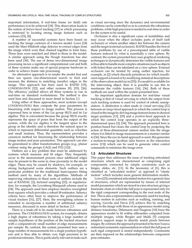
The features used in this work for tracking are the visibleedges of a CAD model of the part to be tracked. These arestrong features that can be reliably found in the imagebecause they have a significant spatial extent. Furthermore,this means that a number of measurements can be made alongeach edge and, thus, they may be accurately localized withinan image. This approach also takes advantage of the apertureproblem (that the component of motion of an edge, tangent toitself, is not observable locally). This yields a significantbenefit since the search for intensity discontinuities in thevideo image can be limited to a one dimensional path that liesalong the edge normal, n̂ (see Fig. 1) and, thus, has linearcomplexity in the search range, rather than quadratic [7]. Thisreduction in complexity makes it possible to track complex
934 IEEE TRANSACTIONS ON PATTERN ANALYSIS AND MACHINE INTELLIGENCE, VOL. 24, NO. 7, JULY 2002
Fig. 1. Computing the normal component of the motion and generator
vector fields.

structures in real time on a standard workstation withoutspecial hardware. The normal component of the motionfields, Li are then also computed (as fi � Li � n̂) and d can befitted as a linear combination of the fi to give a linearizedestimate of the 3D motion.
In order to track the edges of the model as lines in the
image, it is necessary to determine which (parts of) lines are
visible at each frame and where they are located relative to
the camera. This work uses binary space partition trees [28]
to dynamically determine the visible features of the model
in real-time. This technique allows accurate frame rate
tracking of complex structures such as the ship part shown
in Fig. 2. As rendering takes place, a stencil buffer is used to
locate the visible parts of each edge by querying the buffer
at a series of points along the edge prior to drawing the
edge. Where the line is visible, sample points are assigned
to search for the nearest intensity discontinuity in the video
feed along the edge normal (see Fig. 3).Fig. 4 shows system operation. At each cycle, the system
renders the expected view of the object (Step a) using its
current estimate of the projection matrix, P . The visible
edges are identified and sample points are assigned at
regular intervals in image coordinates along these edges
(Step b). The edge normal is then searched in the video image
for a nearby edge (Step c). Typically, m � 400 samples are
assigned and measurements made in this way. The system
then projects this m-dimensional measurement vector onto
the six-dimensional subspace corresponding to Euclidean
transformations (Step d) giving the least-squares estimate of
the motion,M. The Euclidean part of the projection matrix,E
is then updated by right multiplication with this transforma-
tion (Step e). Finally, the new projection matrix P is obtained
by multiplying the camera parameters K with the updated
Euclidean matrix to give a new current estimate of the local
position (Step f). The system then loops back to Step a.
2.2 Computing the Motion
Step (d) in the process involves the projection of themeasurement vector onto the subspace defined by theEuclidean transformation group. This subspace is given bythe f�i which describe the magnitude of the edge normalmotion that would be observed in the image at the �th
sample point for the ith group generator. These can be
considered as a set of six m-dimensional vectors whichdescribe the motion in the image for each of the six modesof Euclidean transformation. The system then projects them-vector corresponding to the measured distances (to theobserved edges) onto the six-dimensional subspacespanned by the transformation vectors. This correspondsto the geometric transformation of the part which best fitsthe observed edge positions and is found by minimising thesquare error between the transformed edge position and the
actual edge position (in pixels). This process is performedusing the standard least-squares algorithm as follows:
DRUMMOND AND CIPOLLA: REAL-TIME VISUAL TRACKING OF COMPLEX STRUCTURES 935
Fig. 2. Image and CAD model of ship part.
Fig. 3. Sample points are assigned and distances measured.

vi �X�
d�f�i ; �11�
Cij �X�
f�i f�j ; �12�
�i � Cÿ1ij vj: �13�
Giving �i which are the six coefficients of the projectedvector. It can be seen that setting �i � �i gives the minimum(least-squares) solution to
S �X�
d� ÿ �if�i� �2 �14�
since@S
@�i� ÿ2
X�
f�i d� ÿ �jf�j� �
�15�
and setting �i � �i and substituting (13) gives
@S
@�i� ÿ2
X�
f�i d� ÿ f�i f�j Cÿ1
jk
X�0f�0k d
�0 �16�
� ÿ2X�
�f�i d�� � 2CijCÿ1jk
X�0f�0k d
�0 � 0: �17�
The �i are thus the coefficients of a linear approximation tothe Euclidean motion which minimizes the sum squarederror between the model and the observed lines. Whenmore complex configurations are examined, it will becomeimportant to consider how the sum squared error varieswhen �i 6� �i. Setting �i � �i � "i, (15) gives
@S
@�i� 0� 2
X�
f�i f�j "j �18�
� 2Cij"j �19�
and integrating gives S � S0 � "iCij"j where S0 � Sj"�0:
�20�All that remains for the rigid body tracker is to compute
the matrix for the motion of the model represented by the �iand apply it to the matrix E in (2) which is done by usingthe exponential map:
Et�1 � Et expXi
�iGi
!: �10�
The system is therefore able to maintain an estimate of E(and, hence, P ) by continually computing the coefficients �iof interframe motions (see Fig. 5). One key advantage of thisapproach is that it is possible to extend it to include morecomplex situations such as tracking camera parameters inaddition to object motion.
2.3 Robustness
The naõÈve least-squares algorithm presented in Section 2.2 isvulnerable to instabilities caused by the presence of outliers.This is because the sum-of-squares objective function can besignificantly affected by a few measurements with large
936 IEEE TRANSACTIONS ON PATTERN ANALYSIS AND MACHINE INTELLIGENCE, VOL. 24, NO. 7, JULY 2002
Fig. 4. Tracking system operation.
Fig. 5. Frames from video of tracking sequence: The CAD model of the ship part is superimposed on the video image using the estimate of theprojection matrix.

errors. Equivalently, the corresponding Gaussian distribu-tion dies off far too quickly to admit many samplemeasurements at a large number of standard deviations.
Two standard techniques for handling this problem areto use RANSAC (as in [2]) or to substitute a robustM-estimator for the least-squares estimator by replacingthe objective function with one that applies less weightingto outlying measurements [20]. The latter approach is usedhere for speed and is achieved by modifying the least-squares algorithm and replacing (11) and (12) with:
vi �X�
s�d��d��L�i � n̂��; �22�
Cij �X�
s�d���L�i � n̂���L�j � n̂��: �23�
A common choice for the weighting function, s is:
s�d�� � 1
c� jd�j ; �24�
which corresponds to replacing the Gaussian distributionwith one of the form:
P �d� � eÿjdj 1� dc
� �c; �25�
which behaves like a Gaussian for d� c and a Laplacian ford� c. The parameter c is chosen here to be approximately onestandard deviation of the inlying data. This approach isknown as iterative reweighted least squares (IRLS) since sdepends on d, which changes with each iteration. In thecurrent implementation, only a single iteration is performedfor each frame of the video sequence and convergence occursrapidly over sequential frames. Incorporating IRLS into thesystem improves its robustness to occlusion (see Fig. 6). Thefunction s controls the confidence with which each measure-ment is fitted in the least-squares procedure and, thus, can beviewed as representing the saliency of the measurement.
2.3.1 Extending IRLS
This can be further exploited by extending IRLS byincorporating a number of additional criteria into thereweighting function. The measures presented here repre-sent a heuristic method for applying saliency criteria toimprove tracking performance and have been selected inorder to deal with particular problems that have been
observed during the operation of this system. The generalapproach of modifying the reweighting function, s, pro-vides a powerful method of incorporating domain knowl-edge within the least-squares framework in a conceptuallyintuitive manner. This could be applied to other saliencycriteria that have been developed, for example, based on theshape of the Sum-of-Squared-Differences surface aroundthe proposed feature match [31], [27].
The criteria presented below are chosen to improve therobustness of the system when it is exposed to criticalconfigurations which have been identified as causinginstabilities. The saliency or reweighting of each measure-ment is modified to include four additional terms. The firstthree of these terms address statistical saliency (can a feature bedetected reliably?), while the fourth is concerned withanalytical saliency (does the feature constrain the pose estimate?).
1. Multiple edges. When the tracker sees multipleedges within its search range, it is possible for thewrong one to be chosen. Typically, many trackers onthe same edge will do this, compounding theproblem. To reduce this problem, the saliency isinversely proportional to the number of edgestrength maxima visible within the search path.
2. Many trackers disappear simultaneously. If an edgeof the CAD model runs parallel and near to aboundary of the image, it is possible for a smallmotion to take the entire edge out of the field ofview. This entails a sudden change in the set oftrackers used and may cause a sudden apparentmotion of the model. This sudden change in thebehavior of the tracker can be removed by con-structing a border at the edge of the image. Thesaliency of nodes within this border is weakenedlinearly to zero as the pixel approaches the edge. Aborder of 40 pixels has been found to be sufficientlylarge for this purpose.
3. Poor visibility. Generally, the best measurementscome from the strongest edges in the image sinceweak edges may be difficult to locate precisely. Thisis taken into account by examining the edgestrengths found in the search path. If the edgestrength along a search path is below a threshold, nomeasurement is made for that node. Between thisthreshold and a higher threshold (equal to doublethe lower one), the saliency of the node is varied
DRUMMOND AND CIPOLLA: REAL-TIME VISUAL TRACKING OF COMPLEX STRUCTURES 937
Fig. 6. Frames from tracking sequence with occlusion. The tracking system can provide reasonable estimates of the moving pose despite occlusionof up to approximately half the visible features.

linearly. Above the higher threshold, the visibilitydoes not affect the saliency. These thresholds arechosen manually so that at the upper threshold,matches are dominated by features present in theCAD model rather than by noise.
4. Weak conditioning. If the majority of the trackersbelong to a single plane of the model (for example thefeature rich front plane of the ship part) which is fronton to the camera, then the least-squares matrixgenerated by these nodes becomes more weaklyconditioned than in the general configuration. Thiscan be improved by increasing the saliency ofmeasurements that help to condition the least-squaresmatrix. If the vector comprising the six image motionsat node i lies in the subspace spanned by the eigenvectors of Cij corresponding to the smallest eigenvalues, then that node is particularly important inconstraining the estimated motion. This is implemen-ted by the simple expedient of doubling the saliencywhen �L�i � n̂���L�j � n̂��Cÿ1
ij is greater than the geo-metric mean of that quantity, computed over thevisible features in the image.
A series of 10 experiments were performed in which thetarget structure was moved through configurations whichexhibit the characteristics described above. Two trackers(one with and one without modified reweighting criteria)were run concurrently on this data. On five of theexperiments, the unmodified tracker lost track of the target,while the modified version was able to successfullymaintain track on all 10 occasions.
2.4 Visual Servoing System
A visual servoing system has been developed using the visualtracking system described in the previous sections. Thissystem (shown in Fig. 7) takes the Euclidean matrix,E, outputfrom the tracking system and uses this within a nonlinearcontrol law to provide feedback to servo the robot to a storedtarget pose. These poses are learned using the principle ofteaching-by-showing in which the robot is placed into thetarget pose by the supervisor and records the observed pose
given by the tracker,Et. The inverse of this target matrix,Eÿ1t ,
is easily computed and the product of this with the currentposition matrix yields the transformation from the targetposition to the current position (Fig. 7a)
T � EEÿ1t : �26�
The translation and rotation vectors that must be applied tothe robot are then easily extracted from this representation(Fig. 7b). (here, i; j; k � 1; 2; 3):
ti � Ti4; �27�r0i �
1
2�ijkTjk;
ri � r0i sinÿ1�jr0j�jr0j : �28�
The vectors t and r are then multiplied by a gain factor andsent to the robot as end effector translation and rotationvelocities (Fig. 7c). The gain is dependent on the magnitudesof t and r so that small velocities are damped to obtain higherprecision, while large errors in position may be responded toquickly. A maximum velocity clamp is also applied for safetyreasons and to prevent possible instabilities due to latency.Figs. 8 and 9 show the visual servoing system in action,performing closed loop control tracking a moving part andtracing a path between recorded waypoints.
2.5 Results
The tracking system and visual servoing system have beentested in a number of experiments to assess their performanceboth quantitatively and qualitatively. These experimentswere conducted with an SGI O2 workstation (225 MHz)controlling a Mitsubishi RV-E2 robot.
2.5.1 Stability of the Tracker with Respect to
Image Noise
The stability of the tracker with a stationary structure wasmeasured to assess the effect of image noise on the tracker.The standard deviation of position and rotation as measured
938 IEEE TRANSACTIONS ON PATTERN ANALYSIS AND MACHINE INTELLIGENCE, VOL. 24, NO. 7, JULY 2002
Fig. 7. Visual servoing system operation.
from the Euclidean matrix were measured over a run of100 frames. From a viewing distance of 30 cm, the apparentr.m.s. translational motion was found to be 0.03 mm with ther.m.s. rotation being 0.015 degrees.
2.5.2 Accuracy of Positioning
The accuracy of positioning the robot was measured with twoexperiments. First, the ship part was held fixed and the robotasked to home to a given position from a number of differentstarting points, each of which was a long way from the targetposition (a few tens of centimeters and a few tens of degrees).When the robot had ceased to move, the program wasterminated and the robot's position queried. The standarddeviation of these positions was computed and the r.m.s.translational error was found to be 0.08 mm with the r.m.s.rotation being 0.06 degrees. These runs were performedconsecutively with the tracker running continuously.
The second experiment was performed by positioningthe ship part on an accurate turntable. The part was turnedthrough 15 degrees in one degree rotations and the robotasked to move to the same relative target position each time.Again, the position of the robot was queried and a circle wasfitted to the data. The residual error was computed andfound to give an r.m.s. positional error of 0.12 mm permeasurement (allowing for the three degrees of freedomabsorbed into fitting the circle). Again, the tracker was runcontinuously throughout the experiment and servoing foreach stage was performed from the pose attained at the endof the previous stage.
2.6 Online Camera Calibration
The system presented thus far requires that the internalcamera parameters (the matrix K in (1)) be known. Thissection presentsamethod for extendingthe tracking systemto
incorporate estimation and tracking of these parametersonline.
The internal characteristics of a pinhole camera can bedescribed with five parameters. These are the focal length,aspect ratio, u and v coordinates of the principal point, andthe skew [14]. The matrix of camera parameters is shown in(1). In practice, the skew of the camera is known to be zeroand we enforce that condition here. Thus, there are just fourparameters to be modeled.
For each of these parameters, there is an associated vectorfield, just as for motion in space. The vector fieldscorresponding to the camera parameters can be easilydescribed in terms of the u
v
ÿ �coordinates in the image plane.
This creates four new vector fields,Li; �7 � i � 10�. These areadded to the vector fields already used for tracking in thesystem which then fits a least-squares solution in 10 dimen-sions instead of six. The resulting system is then able todynamically track the camera parameters in addition to themotion of the target and is able, for example, to distinguishbetween motion towards the target and a zoom where there issubstantial three-dimensional structure present in the view.Fig. 10 shows model reprojection using (deliberately poor)initial estimates of the camera parameters, together withreprojection using the parameters computed using thismethod. The initial estimate has a 10 percent error in theaspect ratio and a focal length double that of the lens.Convergence is fast, taking only 5-10 iterations.
One difficulty that can be introduced when tracking ofinternal camera parameters is activated is that the problemis much more likely to become ill-posed, in which case thematrix C in (12) becomes ill-conditioned. This can occur, forexample, when the camera sees only a single plane of imagefeatures parallel to the image plane which causes anambiguity between translation and focal length. Becausethese critical situations can often occur, internal camera
DRUMMOND AND CIPOLLA: REAL-TIME VISUAL TRACKING OF COMPLEX STRUCTURES 939
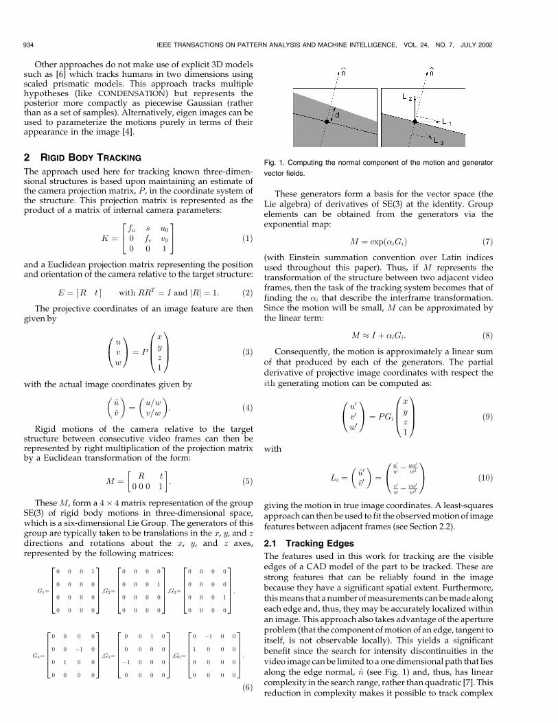
Fig. 8. Closed-loop visual servoing. The task is to maintain a fixed spatial position relative to the workpiece. This can be seen from the presence ofthe wire which is rigidly mounted relative to the camera and, hence, also maintains a fixed pose relative to the workpiece.
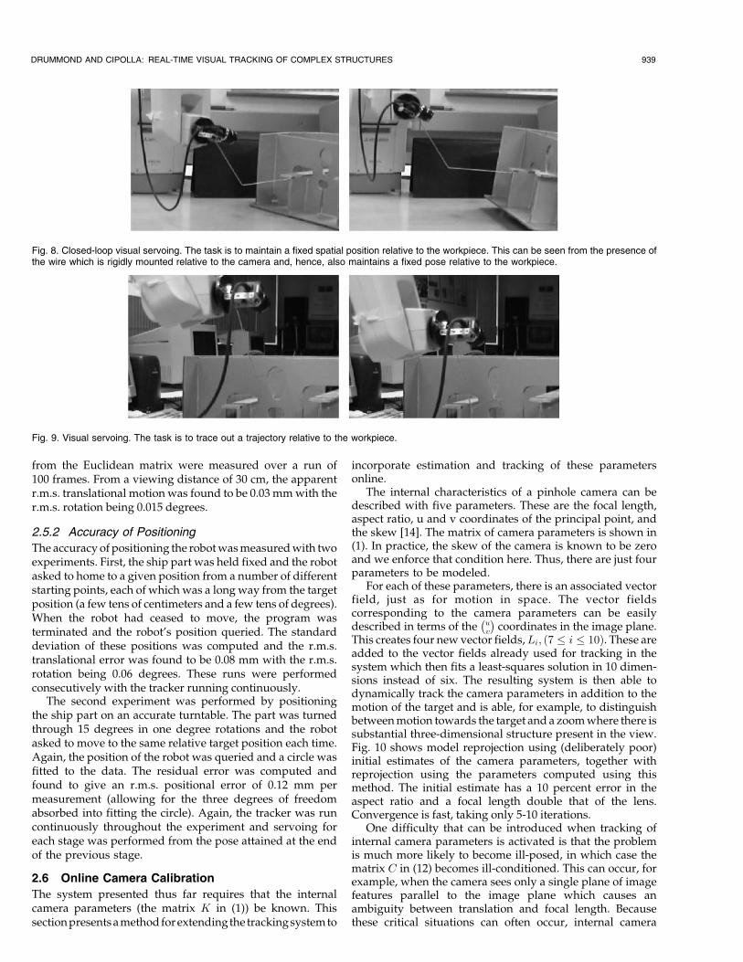
Fig. 9. Visual servoing. The task is to trace out a trajectory relative to the workpiece.

calibration is performed in an environment with rich three-dimensional structure and the parameters are then heldfixed for the remainder of the task.
2.7 Results
In order to assess the performance of this method of cameracalibration, two experiments were conducted.
2.7.1 Stability with Respect to Image Noise
First, the configuration of the camera and a calibration gridwere kept fixed and the calibration calculated on a series ofruns in order to assess the impact of image noise on thecalibration. An 8.5 mm lens was used for this experiment.The mean and standard deviation of the focal length(f � ���������
fufvp
), aspect ratio(a � fu=fv) and principal point(u0; v0) over these runs were computed. The results areshown in Table 1. In all cases, the standard deviation wasO�10ÿ4� times the characteristic scale (for the principalpoint, this is the focal length).
2.7.2 Variation with Respect to Configuration
Second, a series of runs were performed in which theconfiguration was varied in order to provide an estimate ofthe true accuracy of the calibration measurements. A 16 mmlens was used for this experiment and the results are shown inthe last column of Table 1. The standard deviation valuesobtained in this experiment were all less than 1 percent of thecharacteristic scale (with the exception of the y component ofthe principal point which was slightly larger). This compareswell with a standard calibration technique [14] which wastested with images captured from the sequences and alsogenerated errors of O(1 percent).
3 COMPLEX CONFIGURATIONS
The rigid body tracking system presented in the previoussections is now used as the basis of an approach which isdesigned to operate in more complex configurations. Aunified framework for constructing tracking systems withintheseconfigurations is now presented,which takes advantageof the formulation and computational operation of the rigidbody tracker. Such configurations arise in a number of ways:
Multiple cameras. It is often desirable to use more than onecamera to obtain information about a scene since multipleview configurations can provide higher pose precision(especially when a large baseline is used) and also increasethe robustness of the tracker.
Multiple targets. There are many situations in whichknowing the relationship between the camera and asingle target is insufficient. This occurs particularly whenthe position of the camera is not of direct interest. Inthese situations, it is often desirable to measure therelationship between two or more targets that are presentin the scene, for example, between two vehicles and theroad, or between a robot tool and its workpiece.
Articulated targets. Many targets of interest are not simplerigid bodies, but contain internal degrees of freedom. Thispaper only considers targets which comprise a number ofrigid components connected by hinges or slides, etc.
All of these configurations can be handled using acommon approach in which multiple instances of the rigidbody tracker are executed concurrently, one per componentper camera. Because this naõÈve approach introduces moredegrees of freedom into the system than are really present,it is necessary to couple the rigid body trackers together in
940 IEEE TRANSACTIONS ON PATTERN ANALYSIS AND MACHINE INTELLIGENCE, VOL. 24, NO. 7, JULY 2002
Fig. 10. When camera calibration is activated, the tracking system can adjust the internal camera parameters in order to improve the fit between themodel and the image.
TABLE 1Results of Camera Calibration Experiments Showing the Stability with Respect to Image Noise
and the Variation in Estimate Across Different Configurations

order to condition the problem and also ensure that thesolution corresponds to a physically correct configuration.
For example, three cameras viewing two structures wouldrequire six concurrent trackers. Even if the cameras andstructures can move independently, there are only 24 degreesof freedom in the world, whereas the system of six trackerscontains 36. The natural approach to this problem is to imposeall of the constraints that are known about the world upon thetracking system.
3.1 Constrained Tracking
Multiple Cameras. In the case in which multiple camerasare used to view a scene, it may be that the cameras areknown to be rigid relative to one another in space. In thiscase, there are six constraints that can be imposed on thesystem for every camera additional to the first.
Multiple structures. Where the system is being used totrack multiple structures, it is often the case that otherconstraints apply between the structures. For example,two cars will share a common ground-plane and, thus, asystem in which two vehicles observed from an airbornecamera will have three constraints that apply to the raw12 dimensions present in the two trackers, reflecting thenine degrees of freedom present in the world.
Articulated structures. This is really a special case ofconstrained multiple structures, except that there areusually more constraints. A hinged structure, for example,has seven degrees of freedom (six for position in the worldand one for the angle of the hinge). When the twocomponents of the structure are independently tracked,there are five hinge constraints which apply to the system.
Because these constraints exist in the world, it is highlydesirable to impose them on the system of trackers. Each ofthe trackers generates an estimate for the motion of onerigid component in a given view, �i in (13) as well as amatrix Cij in (12), which describes how the error variesaround that estimate. Thus, the goal is to use both of thesepieces of information from each tracker to obtain a globalmaximum a posteriori estimate of the motion subject tosatisfying the known constraints. This raises three issueswhich must be addressed:
1. Measurements from different trackers are made indifferent coordinate frames.
2. How can the constraints be expressed?3. How can they then be imposed?
3.1.1 Coordinate Frames
The first difficulty is that the �i and the Cij are quantities inthe Lie algebra deriving from the coordinate frame of the
object being tracked. Since these are not the same, ingeneral, for distinct trackers, a method for transforming the�i and Cij from one coordinate frame to another is needed.Specifically, this requires knowing what happens to the Liealgebra of SE(3) under IR3 coordinate frame changes. Sincethese frame changes correspond to elements of the Liegroup SE(3), this reduces to knowing what happens to theLie algebra of the group under conjugation by elements ofthe group. This is (by definition) the adjoint representationof the group which is a n� n matrix representation, wheren is the dimensionality of the group (six in the case ofSE(3)). The adjoint representation, ad(M), for a matrixelement of SE(3), M, can easily be computed by consideringthe action of M on the group generators, Gi, by conjugation:
MGiMÿ1 �
Xj
ad�M�ijGj: �29�
If (with a slight abuse of notation) M � �Rjt�, this isgiven by
ad�M� � R �t^�R0 R
� �where�t^�ij � "ijktk: �30�
To see that these 6� 6 matrices do form a representation ofSE(3), it is only necessary to ensure that multiplication ispreserved under the mapping into the adjoint space (thatad�M1�ad�M2� � ad�M1M2�) which can easily be checkedusing the identityR1�t2^�Rÿ1
1 � �R1t2^�. Thus, ifM transformspoints from coordinate frame 1 into frame 2, then ad�M�transforms a vector in the Lie algebra of frame 1 into the Liealgebra of frame 2. Using this, the quantities in (11), (12), and(13) can be transformed as follows (see Figs. 11a and 11b):
v0 � ad�M�ÿT ; v �31��0 � ad�M��; �32�C0 � ad�M� C ad�M�T : �33�
3.1.2 Expressing Constraints
It is useful to have a generic method for expressing theconstraints that are present on the given world configura-tion since this increases the speed with which models fornew situations may be constructed. In the Lie algebraformalism, it is very easy to express the constraints thatdescribe a hinge, a slide, or the existence of a commonground plane since the relationship between velocities inthe algebra and the constraints is a simple one.
The presence of a hinge or common ground plane areholonomic constraints which reduce the dimensionality ofthe configuration space by five and three, respectively. This
DRUMMOND AND CIPOLLA: REAL-TIME VISUAL TRACKING OF COMPLEX STRUCTURES 941
Fig. 11. Applying the constraints: Estimates and errors are computed for motions 1 and 2 (a), the estimate and error of motion 2 are mapped into 1'scoordinate frame (b), the constraint is applied there (c), and then the new estimate of motion 2 is mapped back into its own frame (d).

results in a seven- or nine-dimensional submanifoldrepresenting legal configurations embedded within theraw 12-dimensional configuration manifold of the two rigidcomponents. The tangent space to this submanifoldcorresponds to the vector space of velocities which locallyrespect the constraint. This means that at each legalconfiguration there is a linear subspace of legal velocities,which implies that the constraints on the velocities must belinear (and, also, homogeneous since zero velocity results ina legal configuration). Thus, if �1 and �2 correspond to themotions of the two rigid components (in their Lie algebras),then the constraints must take the form
�1 � ci1 � �2 � ci2 � 0: �34�There must be five such c1 and c2 for the hinge or three for
the common ground plane. As a simple example, consider thecase of a hinge in which the axis of rotation passes through theorigin of component 1's coordinate frame and lies along itsz axis. When the motions of the two parts are considered in1's frame, then their translations along all three axes must bethe same as must their rotations about the x and y axes;only their rotations about the z axis can differ. Sincecomponent 2's motion can be transformed into 1's coordinateframe using the adjoint representation of the coordinatetransformation, the constraints now take the form
�1 � ci1 � �02 � ci2 � 0; �35�where �02 � ad�Eÿ1
1 E2��2 is the motion of component 2 in1's frame. In this example, the c1 and c2 vectors for the fiveconstraints become particularly simple:
ci1 �
100000
26666664
37777775;010000
26666664
37777775;001000
26666664
37777775;000100
26666664
37777775;000010
26666664
37777775 �1 � i � 5� �36�
with ci2 � ÿci1. Constraints 1, 2, and 3 say that the x, y, andz axis translations of the two components must be the samewhen measured in the coordinate frame of component 1.Further, constraints 4 and 5 say that the rotations about the xand y axes of this coordinate frame must also be the same.Thus, the only thing that is permitted to differ is the rotationabout the z axis in this coordinate frame which corresponds toarticulation of the hinge.
In the case of a common ground plane in 1's x-y plane,only constraints 3, 4, and 5 are needed. If the hinge orground plane are placed elsewhere, then the adjointrepresentation can be used to transform the constraints byconsidering the Euclidean transformation which takes thatsituation back to the simple one.
3.1.3 Imposing Constraints
Since the constraints have a particularly simple form,finding the optimal �1 and �02 is also an easy matter. Thisis done by modifying the least-squares fitting procedureused for the single tracker which is adapted so that themotion which gives the least-square error subject to satisfyingthe constraints is found. Given the � and C computed in (11),(12), and (13), then (20) gives the increase in sumsquared error if the motion � is used in place of � as�� ÿ ��C�� ÿ ��. Thus, given the independent solutions for
the two motions ��1; C1� and ��02; C02�, the aim is to find �1
and �02 such that
��1 ÿ �1�C1��1 ÿ �1� � ��02 ÿ �02�C02��02 ÿ �02� �37�is minimized subject to �1 � ci1 � �02 � ci2 � 0: �38�
This is a constrained optimization problem and ideal forsolving by means of Lagrange multipliers. Thus, thesolution is given by the constraints in (38) and
rÿ��1 ÿ �1�TC1��1 ÿ �1� � ��02 ÿ �02�TC02��02 ÿ �02��
� �irÿ�T1 c
i1 � �0T2 ci2
� � 0�39�
with r running over the 12 dimensions of �1
�02
� �. This
evaluates to
2C1��1 ÿ �1�2C2��02 ÿ �02�
� �� �i ci1
ci2
� �� 0: �40�
Thus; �1 � �1 ÿ 1
2Cÿ1
1 �ici1
and �02 � �02 ÿ1
2C0ÿ1
2 �ici2:
�41�
Substituting (38) back into (41) gives
ci1 � �1 � ci2 � �02 ÿ1
2�j ci1 � Cÿ1
1 cj1 � ci2 � C0ÿ12 cj2�
� �� 0: �42�
So, the �i are given by
Aij � ci1 � Cÿ11 cj1 � ci2 � C0ÿ1
2 cj2; �43�li � 2 ci1 � �1 � ci2 � �02
ÿ �; �44�
�i � Aÿ1ij lj: �45�
The �i can then be substituted back into (41) to obtain �1
and �02 (see Fig. 11c), from which �2 can also be obtained by�2 � ad�Eÿ1
2 E1��02 (see Fig. 11d). The � can then be used toupdate the configurations of the two rigid parts of thehinged structure giving the configuration with the least-square error that also satisfies the constraints.
4 RESULTS
4.1 Multiple CamerasA multicamera system was developed using up to threecameras multiplexed using the red, green, and bluecomponents of a 4:2:2 digital signal to track the pose of arigid structure. A number of experiments were conductedusing this multiple camera configuration. In which thecameras are known to be fixed relative to each other. Theseare the only experiments in which PAL frame rate (25 Hz)was not achieved, with typical performance being around60-75 percent of frame rate (14-19 Hz) when all threecameras were in use.
4.1.1 AccuracyAn experiment was conducted in order to assess how the useof multiple cameras can improve accuracy. In a single view, itis usually the case that the estimate of the position of astructure is much worse along the camera's optical axis thanin orthogonal directions because the position of features inthe image varies more slowly with motion along this axis. Inthis experiment, the rms error in estimated position using asingle camera was 0.97 mm with an rms error in orientation of
942 IEEE TRANSACTIONS ON PATTERN ANALYSIS AND MACHINE INTELLIGENCE, VOL. 24, NO. 7, JULY 2002
0.0028 radians. By placing a second camera so that it views thestructure from an orthogonal direction, the position of thepart can be known to much higher precision. Combining theinformation from the two cameras reduced the rms estimateof position to 0.29 mm and the rms error in orientation to0.0018 radians. This large improvement is due to the fact thatthe error distributions from the two cameras do not have axesof large variation in common.
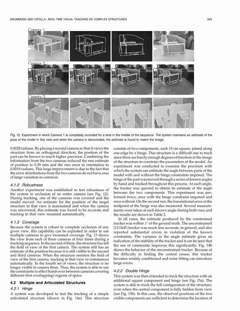
4.1.2 RobustnessAnother experiment was established to test robustness ofthe system to occlusion of an entire camera (see Fig. 12).During tracking, one of the cameras was covered and themodel moved. An estimate for the position of the targetstructure in that view is maintained and when the camerawas uncovered, this estimate was found to be accurate andtracking in that view resumed automatically.
4.1.3 CoverageBecause the system is robust to complete occlusion of anygiven view, this capability can be exploited in order to usemultiple cameras to give increased coverage. Fig. 13 showsthe view from each of three cameras at four times during atracking sequence. In the second of these, the structure has leftthe field of view of the first camera. The system still has anestimate of the position because it is still visible to the secondand third cameras. When the structure reenters the field ofview of the first camera, tracking in that view re-commencesautomatically. In the fourth set of views, the structure is nolonger visible in camera three. Thus, the system is able to usethe constraints to effect hand-over between cameras coveringdifferent (but overlapping) regions of space.
4.2 Multiple and Articulated Structures
4.2.1 Hinge
A system was developed to test the tracking of a simplearticulated structure (shown in Fig. 14a). This structure
consists of two components, each 15 cm square, joined alongone edge by a hinge. This structure is a difficult one to tracksince there are barely enough degrees of freedom in the imageof the structure to constrain the parameters of the model. Anexperiment was conducted to examine the precision withwhich the system can estimate the angle between parts of themodel with and without the hinge constraints imposed. Thehinge of the part was moved through a series of known anglesby hand and tracked throughout this process. At each angle,the tracker was queried to obtain its estimate of the anglebetween the two components. This experiment was per-formed twice, once with the hinge constraint imposed andonce without. On the second run, the translational error at themidpoint of the hinge was also measured. Several measure-ments were taken at each known angle during both runs andthe results are shown in Table 2.
In all cases, the estimate produced by the constrainedtracker was within 1o of the ground truth. The unconstrained(12 DoF) tracker was much less accurate, in general, and alsoreported substantial errors in violation of the knownconstraints. The variance in the angle estimate gives anindication of the stability of the tracker and it can be seen thatthe use of constraints improves this significantly. Fig. 14bshows the behavior of the unconstrained tracker. Because ofthe difficulty in finding the central crease, this trackerbecomes weakly conditioned and noise fitting can introducelarge errors.
4.2.2 Double Hinge
This system was then extended to track the structure with anadditional square component and hinge (see Fig. 15a). Thesystem is able to track the full configuration of the structure,even when the central component is fully hidden from view(see Fig. 15b). In this case, the observed positions of the twovisible components are sufficient to determine the location of
DRUMMOND AND CIPOLLA: REAL-TIME VISUAL TRACKING OF COMPLEX STRUCTURES 943
Fig. 12. Experiment in which Camera 1 is completely occluded for a time in the middle of the sequence. The system maintains an estimate of the
pose of the model in this view and when the camera is disoccluded, the estimate is found to match the image.

the hidden part. Further, the propagated constraints between
the two end parts of the structure serve to improve the
conditioning of the estimation of their positions.
4.2.3 Filing Cabinet
In order to show the system operating with more complex
objects and also to illustrate operation with sliding rather
than rotating joints, the system was applied to tracking afiling cabinet. The drawer is tracked separately but isconstrained to a single axis of translation relative to thecabinet. Nonholonomic constraints corresponding to thelimits of motion of the drawer have also been imposed. Thefirst two frames in Fig. 16 show a tracking sequence withthis configuration. The constraint is important for stabletracking of the drawer; when this is turned off, the estimate
944 IEEE TRANSACTIONS ON PATTERN ANALYSIS AND MACHINE INTELLIGENCE, VOL. 24, NO. 7, JULY 2002
Fig. 13. Tracking sequence showing three views at four difference times during the sequence. The model leaves and reenters the view of camera 1
which continues tracking without need for reinitialization.
Fig. 14. Tracking a hinge. When the constraints are relaxed, the tracker falls into an erroneous minimum due to the lack of visibility of the central crease.
TABLE 2Results of Experiment Measuring Accuracy of Constrained and Unconstrained Trackers
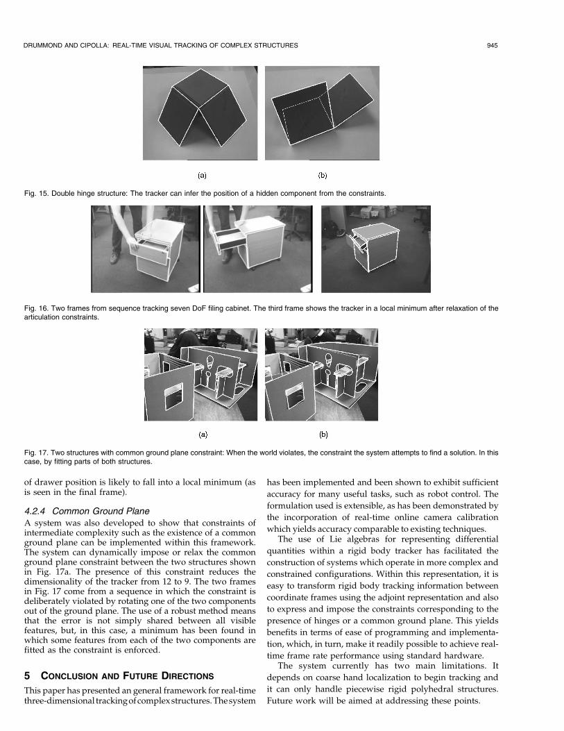
of drawer position is likely to fall into a local minimum (asis seen in the final frame).
4.2.4 Common Ground Plane
A system was also developed to show that constraints ofintermediate complexity such as the existence of a commonground plane can be implemented within this framework.The system can dynamically impose or relax the commonground plane constraint between the two structures shownin Fig. 17a. The presence of this constraint reduces thedimensionality of the tracker from 12 to 9. The two framesin Fig. 17 come from a sequence in which the constraint isdeliberately violated by rotating one of the two componentsout of the ground plane. The use of a robust method meansthat the error is not simply shared between all visiblefeatures, but, in this case, a minimum has been found inwhich some features from each of the two components arefitted as the constraint is enforced.
5 CONCLUSION AND FUTURE DIRECTIONS
This paper has presented an general framework for real-timethree-dimensional trackingofcomplexstructures. Thesystem
has been implemented and been shown to exhibit sufficient
accuracy for many useful tasks, such as robot control. The
formulation used is extensible, as has been demonstrated by
the incorporation of real-time online camera calibration
which yields accuracy comparable to existing techniques.The use of Lie algebras for representing differential
quantities within a rigid body tracker has facilitated the
construction of systems which operate in more complex and
constrained configurations. Within this representation, it is
easy to transform rigid body tracking information between
coordinate frames using the adjoint representation and also
to express and impose the constraints corresponding to the
presence of hinges or a common ground plane. This yields
benefits in terms of ease of programming and implementa-
tion, which, in turn, make it readily possible to achieve real-
time frame rate performance using standard hardware.The system currently has two main limitations. It
depends on coarse hand localization to begin tracking and
it can only handle piecewise rigid polyhedral structures.
Future work will be aimed at addressing these points.
DRUMMOND AND CIPOLLA: REAL-TIME VISUAL TRACKING OF COMPLEX STRUCTURES 945
Fig. 15. Double hinge structure: The tracker can infer the position of a hidden component from the constraints.
Fig. 16. Two frames from sequence tracking seven DoF filing cabinet. The third frame shows the tracker in a local minimum after relaxation of thearticulation constraints.
Fig. 17. Two structures with common ground plane constraint: When the world violates, the constraint the system attempts to find a solution. In thiscase, by fitting parts of both structures.

ACKNOWLEDGMENTS
This work was supported by an EC (ESPRIT) grant
no. LTR26247 (VIGOR) and by an EPSRC grant no. K84202.
REFERENCES
[1] J.K. Aggarwal, Q. Cai, W. Liao, and B. Sabata, ªNonrigid MotionAnalysis: Articulated and Elastic Motion,º Computer Vision andImage Understanding, vol. 70, no. 2, pp. 142-156, 1998.
[2] M. Armstrong and A. Zisserman, ªRobust Object Tracking,º Proc.Second Asian Conf. Computer Vision, pp. 58-62, 1995.
[3] R. Basri, E. Rivlin, and I. Shimshoni, ªVisual Homing: Surfing onthe Epipoles,º Proc. Int'l Conf. Computer Vision (ICCV '98), pp. 863-869, 1998.
[4] M.J. Black and A.D. Jepson, ªEigen Tracking: Robust Matchingand Tracking of Articulated Objects Using a View BasedRepresentation,º Proc. European Conf. Computer Vision '96, vol. 1,pp. 329-342, 1996.
[5] C. Bregler and J. Malik, ªTracking People with Twists andExponential Maps,º Proc. Computer Vision and Pattern Recognition'98, pp. 8-15, 1998.
[6] T.-J. Cham and J.M. Rehg, ªA Multiple Hypothesis Approach toFigure Tracking,º Proc. Computer Vision and Pattern Recognition '99,vol. 2, pp. 239-245, July 1999.
[7] R. Cipolla and A. Blake, ªThe Dynamic Analysis of ApparentContours,º Proc. IEEE Third Int'l Conf. Computer Vision, pp. 616-623, Dec. 1990.
[8] R. Cipolla and A. Blake, ªImage Divergence and Deformationfrom Closed Curves,º Int'l J. Robotics Research, vol. 16, no. 1, pp. 77-96, 1997.
[9] N. Daucher, M. Dhome, J. T. LapresteÂ, and G. Rives, ªModelledObject Pose Estimation and Tracking by Monocular Vision,º Proc.British Machine Vision Conf., pp. 249-258, 1993.
[10] Q. Delamarre and O. Faugeras, ª3D Articulated Models andMulti-View Tracking with Silhouttes,º Proc. Int'l Conf. ComputerVision '99, vol. 2, pp. 716-721, Sept. 1999.
[11] T. Drummond and R. Cipolla, ªReal-Time Tracking of MultipleArticulated Structures in Multiple Views,º Proc. Sixth EuropeanConf. Computer Vision, vol. 2, pp. 20-36, June 2000.
[12] T. Drummond and R. Cipolla, ªApplication of Lie Algebras to VisualServoing,º Int'l J. Computer Vision, vol. 37, no. 1, pp. 21-41, 2000.
[13] B. Espiau, F. Chaumette, and P. Rives, ªA New Approach toVisual Servoing in Robotics,º IEEE T-Robotics and Automation,vol. 8, no. 3, 1992.
[14] O.D. Faugeras, Three-Dimensional Computer Vision: A GeometricViewpoint. MIT Press, 1993.
[15] D.M. Gavrila and L.S. Davis, ª3-D Model-Based Tracking ofHumans in Action: A Multi-View Approach,º Proc. ComputerVision and Pattern Recognition '96, pp. 73-80, 1996.
[16] M. Haag and H.-H. Nagel, ªTracking of Complex DrivingManoeuvres in Traffic Image Sequences,º Image and VisionComputing, vol. 16, pp. 517-527, 1998.
[17] G. Hager, G. Grunwald, and K. Toyama, ªFeature-Based VisualServoing and Its Application to Telerobotics,º Intelligent RoboticSystems, V. Graefe, ed., Elsevier, 1995.
[18] C. Harris, ªGeometry from Visual Motion,º Active Vision, A. Blakeand A. Yuille, eds., chapter 16, pp. 263-284, MIT Press, 1992.
[19] C. Harris, ªTracking with Rigid Models,º Active Vision, A. Blakeand A. Yuille, eds., chapter 4, pp. 59-73, MIT Press, 1992.
[20] P.J. Huber, Robust Statistics. Wiley, 1981.[21] S. Hutchinson, G.D. Hager, and P.I. Corke, ªA Tutorial on Visual
Servo Control,º IEEE T-Robotics and Automation, vol. 12, no. 5,pp. 651-670, 1996.
[22] M. Isard and A. Blake, CONDENSATIONÐConditional DensityPropagation for Visual Tracking,º Int'l J. Computer Vision, vol. 29,no. 1, pp. 5-28, 1998.
[23] D.G. Lowe, ªFitting Parameterised 3-D Models to Images,º IEEETrans. Pattern Analysis and Machine Intelligence, vol. 13, no. 5,pp. 441-450, 1991.
[24] D.G. Lowe, ªRobust Model-Based Motion Tracking through theIntegration of Search and Estimation,º Int'l J. Computer Vision,vol. 8, no. 2, pp. 113-122, 1992.
[25] J. MacCormick and A. Blake, ªSpatial Dependence in theObservation of Visual Contours,º Proc. Fifth European Conf.Computer Vision (ECCV '98), pp. 765-781, 1998.
[26] E. Marchand, P. Bouthemy, F. Chaumette, and V. Moreau,ªRobust Real-Time Visual Tracking Using a 2D-3D Model-BasedApproach,º Proc. Int'l Conf. Computer Vision ,'99, vol. 1, pp. 262-268, Sept. 1999.
[27] N. Papanikolopoulos, ªSelection of Features and Evaluation ofVisual Measurements During Robotic Visual Servoing Tasks,ºJ. Intelligent Robotic Systems, vol. 13, pp. 279-304, 1995.
[28] M. Paterson and F. Yao, ªEfficient Binary Space Partitions forHidden Surface Removal and Solid Modeling,º Discrete andComputational Geometry, vol. 5, no. 5, pp. 485-503, 1990.
[29] A.C. Sanderson, L.E. Weiss, and C.P. Neumann, ªDynamic SensorBased Control of Robots with Visual Feedback,º IEEE J. Roboticsand Automation, vol. 3, pp. 404-417, 1987.
[30] D.H. Sattinger and O.L. Weaver, Lie Groups and Algebras withApplications to Physics, Geometry, and Mechanics. Springer-Verlag,1986.
[31] J. Shi and C. Tomasi, ªGood Features to Track,º Proc. Conf.Computer Vision and Pattern Recognition (CVPR '94), pp. 593-600,June 1994.
[32] C. Taylor and D. Kriegman, ªMinimization on the Lie GroupSO(3) and Related Manifolds,º Technical Report 9405, Yale Univ.,Apr. 1994.
[33] D. Terzopoulos and R. Szeliski, ªTracking with Kalman Snakes,ºActive Vision, A. Blake and A. Yuille, eds., chapter 1, pp. 3-20, MITPress, 1992.
[34] W.J. Wilson, C.C. Williams Hulls, and G.S. Bell, ªRelative End-Effector Control Using Cartesian Position Based Visual Servoing,ºIEEE T-Robotics and Automation, vol. 12, no. 5, pp. 684-696, 1996.
[35] A.D. Worrall, G.D. Sullivan, and K.D. Baker, ªPose Refinement ofActive Models Using Forces in 3D,º Proc. Third European Conf.Computer Vision (ECCV '94), J. Eklundh, ed., vol. 2, pp. 341-352,May 1994.
[36] P. Wunsch and G. Hirzinger, ªReal-Time Visual Tracking of 3-DObjects with Dynamic Handling of Occlusion,º Proc. 1997 Int'lConf. Robotics and Automation, pp. 2868-2873, 1997.
Tom Drummond received the BA degree inmathematics from the University of Cambridgein 1988. From 1989 to 1998, he studied andworked in Australia and in 1998 received thePhD degree from Curtin University in Perth,Western Australia. In 1994, he joined theDepartment of Engineering at the University ofCambridge as a research associate. In 2001, hewas appointed as a university lecturer. Hisresearch interests are in computer vision and
robotics and include real-time visual tracking, visual servoing, andaugmented reality. He is a member of the IEEE Computer Society.
Roberto Cipolla received the BA degree inengineering from the University of Cambridge in1984 and the MSE degree in electrical engineer-ing from the University of Pennsylvania in 1985.From 1985 to 1988, he studied and worked inJapan at the Osaka University of Foreign Studies(Japanese Language) and Electrotechnical La-boratory, Tsukuba (visiting scientist), and hereceived the MEng degree in robotics from theUniversity of Electro-Communications in Tokyo
in 1988. In 1991, he was received the DPhil degree in computer visionfrom the University of Oxford. From 1991 to 1992, he was a ToshibaFellow and engineer at the Toshiba Corporation Research andDevelopment Centre in Kawasaki, Japan. He joined the Department ofEngineering, University of Cambridge in 1992 as a lecturer and a fellowof Jesus College. He became a reader in information engineering in1997 and a professor in 2000. His research interests are in computervision and robotics and include the recovery of motion and 3D shape ofvisible surfaces from image sequences, visual tracking and navigation,robot hand-eye coordination, algebraic and geometric invariants forobject recognition and perceptual grouping, novel man-machine inter-faces using visual gestures, and visual inspection. He has authoredthree books, edited five volumes, and coauthored more than 150 papers.He is a member of the IEEE and the IEEE Computer Society.
946 IEEE TRANSACTIONS ON PATTERN ANALYSIS AND MACHINE INTELLIGENCE, VOL. 24, NO. 7, JULY 2002