realization of optical carpets in the talbot and talbot ... opex talbot carpets.pdf · realization...
TRANSCRIPT
Realization of optical carpets in theTalbot and Talbot-Lau configurations
William B. Case1,2, Mathias Tomandl1, Sarayut Deachapunya1,3 andMarkus Arndt 1
1University of Vienna, Faculty of Physics, Boltzmanngasse 5, A-1090 Wien, 2Grinnell College, P. O. Box 805, Grinnell, Iowa 50112
3Department of Physics, Faculty of Science, Burapha University, Chonburi 20131, Thailand.
Abstract: Talbot and Talbot-Lau effects are frequently used in lenslessimaging applications with light, ultrasound, x-rays, atoms and molecules –generally in situations where refractive optical elementsare non-existent ornot suitable. We here show an experimental visualization ofthe intriguingwave patterns that are associated with near-field interferometry behinda single periodic diffraction grating under plane wave illumination andwhich are often referred to asTalbot carpets or quantum carpets. Wealso show the patterns behind two separated diffraction gratings undernearly-monochromatic but spatially incoherent illumination that illustratethe nature ofTalbot-Lau carpets.
© 2009 Optical Society of America
OCIS codes:(050.1940) Diffraction; (000.2060) Education; (100.3175) Interferometric Imag-ing;
References and links1. H. F. Talbot, “Facts Relating to Optical Science,” Philos. Mag.9, 401–407 (1836).2. E. Lau, “Beugungserscheinungen an Doppelrastern,” Ann.Phys.6, 417 (1948).3. L. Rayleigh, “On Copying Diffraction–Gratings, and some Phenomena Connected Therewith,” Philos. Mag.11,
196 (1881).4. W. Montgomery, “Self-imaging objects of infinite aperture,” J. Opt. Soc. Am.57(6), 772–775 (1967).5. K. Patorski, “Incoherent Superposition of Multiple Self-imaging Lau Effect and Moire Fringe Explanation,” Opt.
Acta30, 745–758 (1983).6. G. J. Swanson and E. N. Leith, “Analysis of the Lau Effect and Generalized Grating Imaging,” J. Opt. Soc. Am.
A 2, 789–793 (1985).7. L. Liu, “Talbot and Lau effects on incident beams of arbitrary wavefront, and their use,” Appl. Opt.28(21),
4668–4678 (1989).8. K. Patorski, “Self-Imaging and its Applications,” inProgress in Optics XXVII, E. Wolf, ed., (Elsevier Science
Publishers B. V., Amsterdam, 1989), pp. 2–108.9. K. Banaszek, K. Wodkiewicz, and W. P. Schleich, “Fractional Talbot effect in Phase Space: A Compact Summa-
tion Formula,” Opt. Express2, 169 – 172 (1998).10. O. Friesch, W. Schleich, and I. Marzoli, “Quantum carpets woven by Wigner functions,” New J. Phys.2(1), 4
(2000).11. S. Mirza and C. Shakher, “Surface profiling using phase shifting Talbot interferometric technique,” Optical En-
gineering44, 013,601 (2004).12. M. Thakur, C. Tay, and C. Quan, “Surface profiling of a transparent object by use of phase-shifting Talbot
interferometry,” Appl. Opt.44(13), 2541–2545 (2005).13. J. Bhattacharya, “Measurement of the refractive index using the Talbot effect and a moire technique,” Appl. Opt.
28(13), 2600–2604 (1989).14. S. Prakash, S. Singh, and A. Verma, “A low cost technique for automated measurement of focal length using Lau
effect combined with Moire readout,” J. Mod. Opt.53(14), 2033–2042 (2006).
#116873 - $15.00 USD Received 10 Sep 2009; revised 16 Oct 2009; accepted 28 Oct 2009; published 2 Nov 2009
(C) 2009 OSA 9 November 2009 / Vol. 17, No. 23 / OPTICS EXPRESS 20966

15. P. Singh, M. Faridi, and C. Shakher, “Measurement of temperature of an axisymmetric flame using shearinginterferometry and Fourier fringe analysis technique,” Opt. Eng.43, 387 (2004).
16. G. Spagnolo, D. Ambrosini, and D. Paoletti, “Displacementmeasurement using the Talbot effect with a Ronchigrating,” J. Opt. A4(6), 376–380 (2002).
17. F. Huang, N. Zheludev, Y. Chen, and F. de Abajo, “Focusingof light by a nanohole array,” Appl. Phys. Lett.90,091,119 (2007).
18. M. Dennis, N. Zheludev, and F. Garcıa de Abajo, “The plasmon Talbot effect,” Opt. Express15(15), 9692–9700(2007).
19. P. Cloetens, J. Guigay, C. De Martino, J. Baruchel, and M.Schlenker, “Fractional Talbot imaging of phasegratings with hard x rays,” Opt. Lett.22(14), 1059–1061 (1997).
20. F. Pfeiffer, T. Weitkamp, O. Bunk and C. David, “Phase retrieval and differential phase-contrast imaging withlow-brilliance X-ray sources,” Nature2, 258–261 (2006).
21. J. F. Clauser and S. Li, “‘Heisenberg Microscope’ Decoherence Atom Interferometry,” Phys. Rev. A50, 2430(1994).
22. M. S. Chapman, C. R. Ekstrom, T. D. Hammond, J. Schmiedmayer, B. E. Tannian, S. Wehinger, and D. E.Pritchard, “Near-Field Imaging of Atom Diffraction Gratings: The Atomic Talbot Effect,” Phys. Rev. A51, R14(1995).
23. S. Nowak, C. Kurtsiefer, T. Pfau, and C. David, “High-Order Talbot Fringes for Atomic Matter Waves,” Opt.Lett. 22, 1430–32 (1997).
24. S. B. Cahn, A. Kumarakrishnan, U. Shim, T. Sleator, P. R. Berman, and B. Dubetsky, “Time-Domain de BroglieWave Interferometry,” Phys. Rev. Lett.79, 784–787 (1997).
25. L. Deng, E. W. Hagley, J. Wen, M. Trippenbach, Y. Band, P. S. Julienne, J. E. Simsarian, K. Helmerson, S. L.Rolston, and W. D. Phillips, “Four-wave mixing with matter waves,” Nature398(6724), 218 (1999).
26. B. Brezger, L. Hackermuller, S. Uttenthaler, J. Petschinka, M. Arndt, and A. Zeilinger, “Matter-Wave Interfer-ometer for Large Molecules,” Phys. Rev. Lett.88, 100,404 (2002).
27. S. Gerlich, L. Hackermuller, K. Hornberger, A. Stibor, H. Ulbricht, M. Gring, F. Goldfarb, T. Savas, M. Muri,M. Mayor, and M. Arndt, “A Kapitza-Dirac-Talbot-Lau interferometer for highly polarizable molecules,” Nat.Phys.3, 711 – 715 (2007).
28. B. J. McMorran and A. D. Cronin, “An electron Talbot interferometer,” New J. Phys.11, 033,021 (2009).29. I. Marzoli, A. Kaplan, F. Saif, and W. Schleich, “Quantumcarpets of a slightly relativistic particle,” Fortschr.
Phys.56(10) (2008).30. M. Berry, I. Marzoli, and W. Schleich, “Quantum Carpets,Carpets of Light,” Phys. World pp. 1–6 (2001).31. M. Berry and S. Klein, “Integer, Fractional and Fractal Talbot Effects” J. Mod. Opt.43, 2139–2164 (1996).32. J. F. Clauser, “Factoring Integers with Youngs N-Slit Interferometer,” Phys. Rev. A53, 4587–4590 (1996).33. S. Wolk, W. P. Schleich, “Quantum carpets: Factorization with degeneracies,” Proceedings of the Middleton
Festival, Princeton, in print (2009).34. J. Yeazell and C. Stroud, “Observation of fractional revivals in the evolution of a Rydberg atomic wave packet,”
Phys. Rev. A43(9), 5153–5156 (1991).35. M. Vrakking, D. Villeneuve, A. Stolow, “Observation of fractional revivals of a molecular wave packet,” Phys.
Rev. A54(1), 37 (1996).36. J. H. Hannay, M. V. Berry, “Quantization of linear maps on atorus-fresnel diffraction by a periodic grating,”
Physica1D 267–290 (1980).
1. Self-imaging of periodic structures
In the early nineteenth century Talbot discovered the self-imaging of periodic structures throughoptical near-field diffraction [1]: When plane-parallel light falls onto an absorption mask withperiodic openings the light will generate images of this grating in multiples of a well-defineddistance, which is now called the Talbot lengthLT (Figure 1).
Interferometric self-imaging is also possible for spatially incoherent light if we add a secondgrating down stream from the first one. It now suffices that thewave is fairly monochromaticbut not necessarily collimated or transversally coherent.Lau identified the arrangements whichgenerate distinct periodic images at various distances between the gratings and the observationscreen [2]. These near-field fringe patterns that are based on a two-grating setup of Figure 2,are now commonly designated as Lau or Talbot-Lau images.
The theory of the optical Talbot effect was first developed byRayleigh [3]. Meanwhile,a large number of theoretical treatments have discussed both the Talbot and the Talbot-Lauphenomena in great detail, with formalisms operating either in real space [4-8] or phase
#116873 - $15.00 USD Received 10 Sep 2009; revised 16 Oct 2009; accepted 28 Oct 2009; published 2 Nov 2009
(C) 2009 OSA 9 November 2009 / Vol. 17, No. 23 / OPTICS EXPRESS 20967
space [9, 10]. Self-imaging of periodic transmission maskshas attracted technological inter-est, as it allows to realize optical elements for waves that cannot be easily manipulated bystandard refractive elements, such as lenses and prisms.
In light optics, the Talbot and Talbot-Lau effects were usedfor generating surface profiles oftransparent objects [11, 12], for measuring the refractionof unknown materials or optical ele-ments [13, 14], for recording temperature profiles in flames [15], for displacement sensors [16]or the sub-wavelength focusing of light [17].
Near-field diffraction at periodic structures has also beenbeneficial in plasmon [18] andx-ray physics [19, 20] and the near-field diffraction also bears fruits in the field of coherentmatter-wave manipulation. The Talbot and Talbot-Lau effect for de Broglie waves were realizedwith atoms [21-25], large molecules [26, 27] and electrons [28]. They were even discussed forrelativistic particles [29].
A recent review article by Berry, Marzoli and Schleich [30] pointed to the beauty of near-fielddiffraction and its many relations to other fields of mathematics and physics such as numberfactoring [31, 32, 33], the quantum particle in the box [31] or revivals of wave packets inRydberg atoms [34] and molecules [35].
The authors of that review coined the termsquantum carpets andcarpets of light to describethe densely woven and appealing interference structures that become apparent when the evolu-tion of the wave intensity is traced as a function of the distance behind the grating. Althoughnumerical simulations of the phenomenon were given [30] andeven atomic carpets have beenstudied experimentally [23], it appears that full carpets of light have not been realized experi-mentally. The purpose of the present contribution is to close this gap.
2. The concept of optical carpets in the Talbot and Talbot-Lau arrangements
We start by giving a short derivation of the Talbot effect which reveals its conceptual simplicityand compares well with our optical experiments. We assume the grating atz = 0 to span thex/y plane with its periodic modulation in thex direction. A plane wave falls onto the gratingwith the wave numberk = 2π/λ . For the Talbot effect we will assume normal incidence butaveraging over non-zero angles of incidenceθ (Figure 2a) will be required for the Talbot-Laueffect.
For static gratings we are allowed to factor out the time dependence of the field and theincident wave can be represented byψ = eikθ x before it enters the grating. Here,kθ = ksin(θ)is the projection of the incident wave vector onto the x-axis.
The grating transforms the wave into
ψ(x,+0) = ψ(x,−0) ·T (x) = ∑n
Anei(kθ +nkd)x = ∑n
Aneik⊥,nx (1)
whereAn represents the components of the Fourier decomposition of the periodic grating trans-mission function T(x). We thus see that diffraction at a grating of periodd simply adds multiplesof kd = 2π/d to the transverse wave vector of the incident plane wave.
When the wave function propagates a distancez from the grating to the screen it acquiresan additional phasekzz wherek⊥,n andkz are the components of the wave vector perpendicularand parallel to thez axis, withkz = [k2− k2
⊥,n]1/2. In the paraxial approximation (k⊥,n ≪ k) we
can expand the phase to second order into
ψ(x,z) = ∑n
An exp
[
i(kθ +nkd)x+ i(k−(kθ +nkd)
2
2k)z
]
. (2)
We now turn explicitly to the Talbot effect and setkθ = 0 and obtain
ψ(x,z) = ∑n
Aneinkdxe−in2π(z/LT ), (3)
#116873 - $15.00 USD Received 10 Sep 2009; revised 16 Oct 2009; accepted 28 Oct 2009; published 2 Nov 2009
(C) 2009 OSA 9 November 2009 / Vol. 17, No. 23 / OPTICS EXPRESS 20968
z
x
yz = 0
z = LT
plane waves gratingscreen with
interference pattern
z
(a)laser
(532 nm)
grating
(!xed)
focus of the
camera lens
lens (f = 15mm)
EMCCD chip
camera
(movable)
motorized translation stage
zcollimation
lensspatial !lter
wavelength !lter
x
y
z
(b)
1 = m23456
z
x
(d)
(c)1
2
3
4
10,5 1,5
1
2
3
4
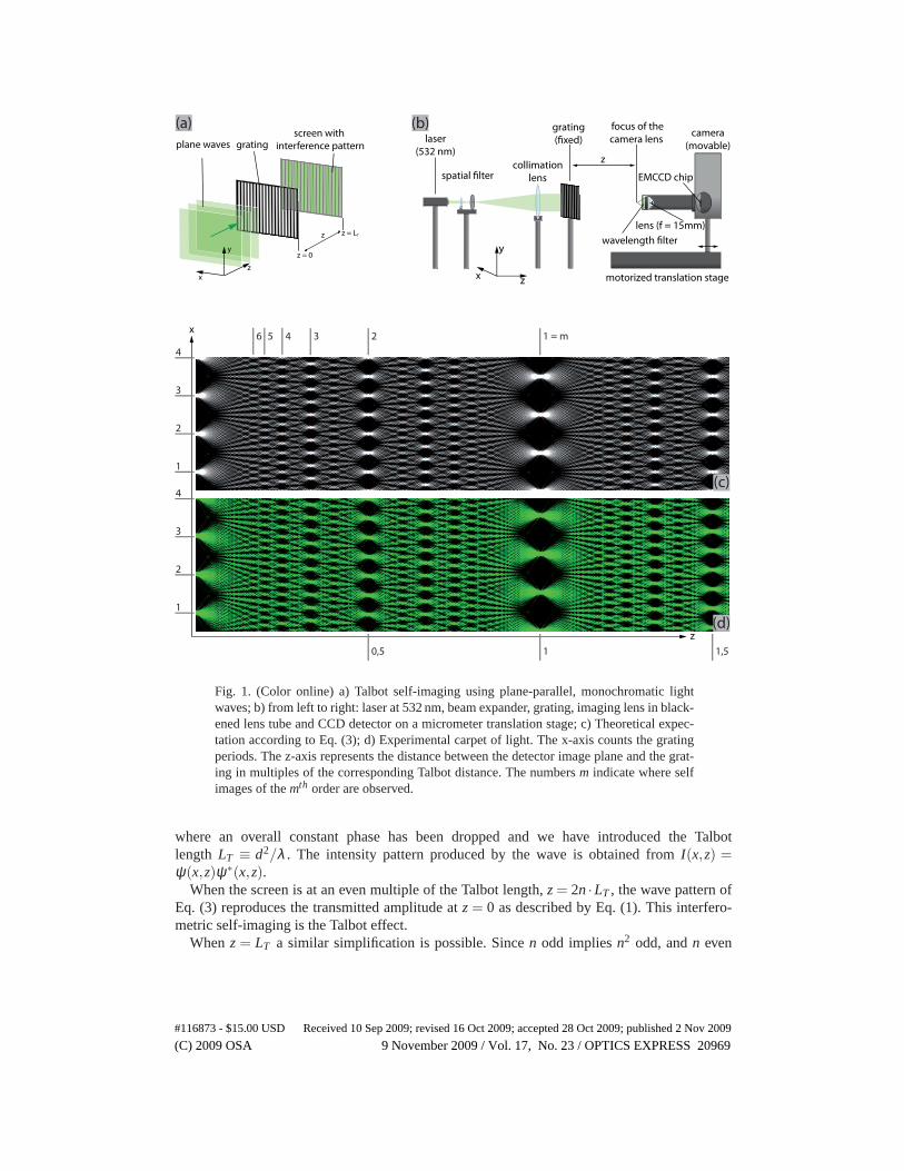
Fig. 1. (Color online) a) Talbot self-imaging using plane-parallel, monochromatic lightwaves; b) from left to right: laser at 532 nm, beam expander, grating,imaging lens in black-ened lens tube and CCD detector on a micrometer translation stage; c) Theoretical expec-tation according to Eq. (3); d) Experimental carpet of light. The x-axis counts the gratingperiods. The z-axis represents the distance between the detector image plane and the grat-ing in multiples of the corresponding Talbot distance. The numbersm indicate where selfimages of themth order are observed.
where an overall constant phase has been dropped and we have introduced the Talbotlength LT ≡ d2/λ . The intensity pattern produced by the wave is obtained fromI(x,z) =ψ(x,z)ψ∗(x,z).
When the screen is at an even multiple of the Talbot length,z = 2n ·LT , the wave pattern ofEq. (3) reproduces the transmitted amplitude atz = 0 as described by Eq. (1). This interfero-metric self-imaging is the Talbot effect.
Whenz = LT a similar simplification is possible. Sincen odd impliesn2 odd, andn even
#116873 - $15.00 USD Received 10 Sep 2009; revised 16 Oct 2009; accepted 28 Oct 2009; published 2 Nov 2009
(C) 2009 OSA 9 November 2009 / Vol. 17, No. 23 / OPTICS EXPRESS 20969

impliesn2 even it follows thate−in2π = e−inπ and Eq. (3) becomes
ψ(x,z = LT ) = ∑n
Aneinkdxe−inπ = ∑n
Aneinkd(x−d/2). (4)
In Eq. (4) we recover the original grating pattern but now displaced inx by half the gratingconstant. For infinitely extended gratings, this shifted self-image will again be repeated at allodd multiples of the Talbot length, i.e. forz = (2n+1)LT .
Interesting patterns also occur at a discrete set of other values ofz. Consider the case whenz can be represented as a rational multiple of the Talbot length, z = (s + p/r)2LT , wheres, pandr are non-negative integers,p < r and p andr are relative primes. Thez dependent factorin Eq. (3) becomes
e−in2π(z/LT ) = e−i2πn2p/r (5)
which is periodic inn with periodr. We expand the expression in Eq. (5) in the discrete Fourierseries
e−iπn2p/r =r−1
∑m=0
ame−i2πmn. (6)
The constantsam can be found using Eq. (7)
r−1
∑n=0
e−i2πmn/rei2πm′n/r = rδmm′ . (7)
For our expression Eq. (6) we find
am =1r
r−1
∑n′=0
e−i2π(n′2−mn′)p/r, (8)
and the field becomes
ψ(x,z) =r−1
∑m=0
am ∑n
Ane−inkd(x−md/r) (9)
=r−1
∑m=0
amψ(x−md/r).
The imaged field is a sum of shifted versions of the original grating pattern, each multipliedwith a factoram. The expression foram given in Eq. (8) is a Gauss sum usually discussed inrelation to number theory and its value depends on the relation between the integersp, r andm [36]. For r odd all of theam’s are nonzero and have the same amplitude, independent ofm.Thus forr odd the field represented in Eq. (10) is a superposition ofr copies of the original fieldeach of the same amplitude but with different phases. Forr even (p odd) half of theam’s arezero while the other half are of the same nonzero amplitude but with different phases. Forr eventhe field represented in Eq. (10) is a superposition ofr/2 copies of the original field each withthe same amplitude but with different phases. Combining these cases we see that forz equal toan integer multiple ofLT the sum in Eq. (10) contains a single copy of the original wave. Forz = LT /2 we get a superposition of two waves, forz = LT /3 or 2LT /3 a superposition of threewaves, and forz = LT /4 or 3LT /4 four waves. Other rational fractions ofLT give similar resultsgenerating a very rich and detailed pattern [31]. If the grating has a small opening fractionf , i.e.if the width of the slits is much smaller than the grating period, these patterns will not overlapin lower orders (r small). In this case the resulting intensity pattern will bea sum of the shifted
#116873 - $15.00 USD Received 10 Sep 2009; revised 16 Oct 2009; accepted 28 Oct 2009; published 2 Nov 2009
(C) 2009 OSA 9 November 2009 / Vol. 17, No. 23 / OPTICS EXPRESS 20970
grating transmission function. When the opening fraction isnot sufficiently small the patternswill overlap and we expect them to be somewhat washed-out butstill with considerable finestructure. As already shown by Berry and Klein [31] these carpets are true fractals and exhibita very intricate pattern.
The grating multiplies the incoming wave alternatingly by one or zero, with an openingfraction of f = 0.1 in our experiments. For such a grating the Fourier components are
A0 = f
An = sin(nπ f )/(nπ) ; for n 6= 0
The resulting intensity distributionI = ψ ·ψ∗ where isψ is taken from Eq. 3. It is reproducedusing in Fig. 1c where the series has been truncated atn = ±25.
For the Talbot-Lau effect we now consider a spatially incoherent input beam. We simulatethis by summing over all intensity distributions produced by waves that enter along a broadrange of angles of incidence.
While the overlaying self-images would smear-out after a single grating, the addition of asecond grating atz = L1 helps refocusing the waves to form again a clear grating image. Thispattern can be viewed on a screen a distanceL2 behind the second grating. The wave just beforethe second grating is given by Eq. (2) withz = L1. If both gratings are identical the second onewill impose the same periodic modulation as did the first, andthe wave just after the secondgrating will be
ψθ (x) = ∑n,m
AnAm exp[i(kθ +(n+m)kd)x] (10)
×exp[−i(kθ +nkd)2L1/(2k)].
When propagated to the detection screen, Eq. (10) gives
ψθ (x) = ∑n,m
AnAm exp[i(kθ +(n+m)kd)x] (11)
×exp[−i(kθ +nkd)2L1/(2k)]
×exp[−i(kθ +(n+m)kd)2L2/(2k)].
The squared modulus of Eq. (11) yields the final intensity pattern and reads
Iθ = ψθ ψ∗θ = ∑
n,m,n′,m′
AnAmA∗n′A
∗m′ exp[ikd(n+m−n′−m′))x] · (12)
×exp[−i2kθ kd [(n−n′)L1 +(n−n′ +m−m′)L2]/2k]
×exp[−ik2d(n
2−n′2)L1/2k]exp[−ik2d((n+m)2− (n′ +m′)2)L2/2k].
In order to account for the spatially incoherent incident beam, we sum over all independentplane waves that originated from a variety of wave vectorkθ
ILau = ∑θ
Iθ . (13)
Because of thekθ -dependence of Eq. (12) the pattern will be washed-out unless the coeffi-cient ofkθ is zero thus we require
L2 =L1
m′−mn−n′ −1
. (14)
This imaging of various modes of the two gratings from an uncollimated beam is called theTalbot-Lau effect. Only terms in the Fourier expansion matching the condition given in Eq.(14)
#116873 - $15.00 USD Received 10 Sep 2009; revised 16 Oct 2009; accepted 28 Oct 2009; published 2 Nov 2009
(C) 2009 OSA 9 November 2009 / Vol. 17, No. 23 / OPTICS EXPRESS 20971
will survive. Since higher order terms are expected to have small amplitudesAn, the pattern willhave a low visibility unless this condition holds among relatively small values ofn,n′,m,m′.Lau’s original choice wasm′−m = n−n′ giving L2 = ∞. Strong patterns can also be obtainedwith m′−m = 2(n−n′) andL2 = L1. Both the Talbot and the Talbot-Lau effects can be imple-mented in a straight-forward way using elementary optical equipment.
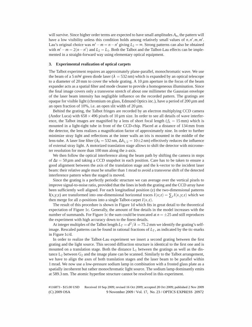
3. Experimental realization of optical carpets
The Talbot experiment requires an approximately plane-parallel, monochromatic wave. We usethe beam of a 5 mW green diode laser (λ = 532 nm) which is expanded by an optical telescopeto a diameter of 20 mm to cover the whole grating. A 10µm aperture in the focus of the beamexpander acts as a spatial filter and mode cleaner to provide ahomogeneous illumination. Sincethe final image covers only a transverse stretch of about one millimeter the Gaussian envelopeof the laser beam intensity has negligible influence on the recorded pattern. The gratings areopaque for visible light (chromium on glass, Edmund Optics inc.), have a period of 200µm andan open fraction of 10%, i.e. an open slit width of 20µm.
Behind the grating, the Talbot fringes are recorded by an electron multiplying CCD camera(Andor Luca) with 658×496 pixels of 10µm size. In order to see all details of wave interfer-ence, the Talbot images are magnified by a lens of short focal length (fL = 15 mm) which ismounted in a light-tight tube in front of the CCD-chip. Placed at a distance of 134 mm fromthe detector, the lens realizes a magnification factor of approximately nine. In order to furtherminimize stray light and reflections at the inner walls an iris is mounted in the middle of thelens-tube. A laser line filter (λ0 = 532 nm,∆λ1/2 = 10±2 nm) effectively reduces the influenceof external stray light. A motorized translation stage allows to shift the detector with microme-ter resolution for more than 100 mm along the z-axis.
We then follow the optical interference along the beam path by shifting the camera in stepsof ∆z = 50µm and taking a CCD snapshot in each position. Care has to be taken to ensure agood alignment between the axis of the translation stage andthe k-vector to the incident laserbeam: their relative angle must be smaller than 1 mrad to avoid a transverse shift of the detectedinterference pattern when the staged is moved.
Since the grating is a perfectly periodic structure we can average over the vertical pixels toimprove signal-to-noise ratio, provided that the lines in both the grating and the CCD array havebeen sufficiently well aligned. For each longitudinal position (z) the two-dimensional patternsI(x,y;z) are transformed into one-dimensional horizontaltracesI(x;z) = ∑y I(x,y;z) which wethen merge for all z-positions into a single Talbot-carpetI(x,z).
The result of this procedure is shown in Figure 1d which fits ingreat detail to the theoreticalexpectation of Figure 1c. Generally, the amount of fine details in the model increases with thenumber of summands. For Figure 1c the sum could be truncated at n =±25 and still reproducesthe experiment with high accuracy down to the finest details.
At integer multiples of the Talbot lengthLT = d2/λ = 75.2 mm we identify the grating’s self-image. Rescaled patterns can be found in rational fractionsof LT , as indicated by the tic-marksin Figure 1c/d.
In order to realize the Talbot-Lau experiment we insert a second grating between the firstgrating and the light source. This second diffraction structure is identical to the first one and ismounted on a translation stage. Both the distance L1 between the gratings as well as the dis-tance L2 between G2 and the image plane can be scanned. Similarly to the Talbot arrangement,we have to align the axes of both translation stages and the laser beam to be parallel within1 mrad. We now use a low-pressure sodium lamp in combination with a frosted glass plate as aspatially incoherent but rather monochromatic light source. The sodium lamp dominantly emitsat 589.3 nm. The atomic hyperfine structure cannot be resolved in this experiment.
#116873 - $15.00 USD Received 10 Sep 2009; revised 16 Oct 2009; accepted 28 Oct 2009; published 2 Nov 2009
(C) 2009 OSA 9 November 2009 / Vol. 17, No. 23 / OPTICS EXPRESS 20972

1 = m2 3 4
z
x
(d)
(c)1
2
3
10,5 1,5
1
2
3
x
y
z
(b)
sodium
lamp
2. grating
(!xed)
1. grating
(movable)
focus of the
camera lens
lens (f = 15mm)
EMCCD chip
camera
(movable)
frosted glass
motorized translation stages
LL
z = LT
z = 2LT
z = 0
monochromatic
spatially
incoherent
waves
gratings
L
L
screen with
interference pattern
zx
y
θ
(a)
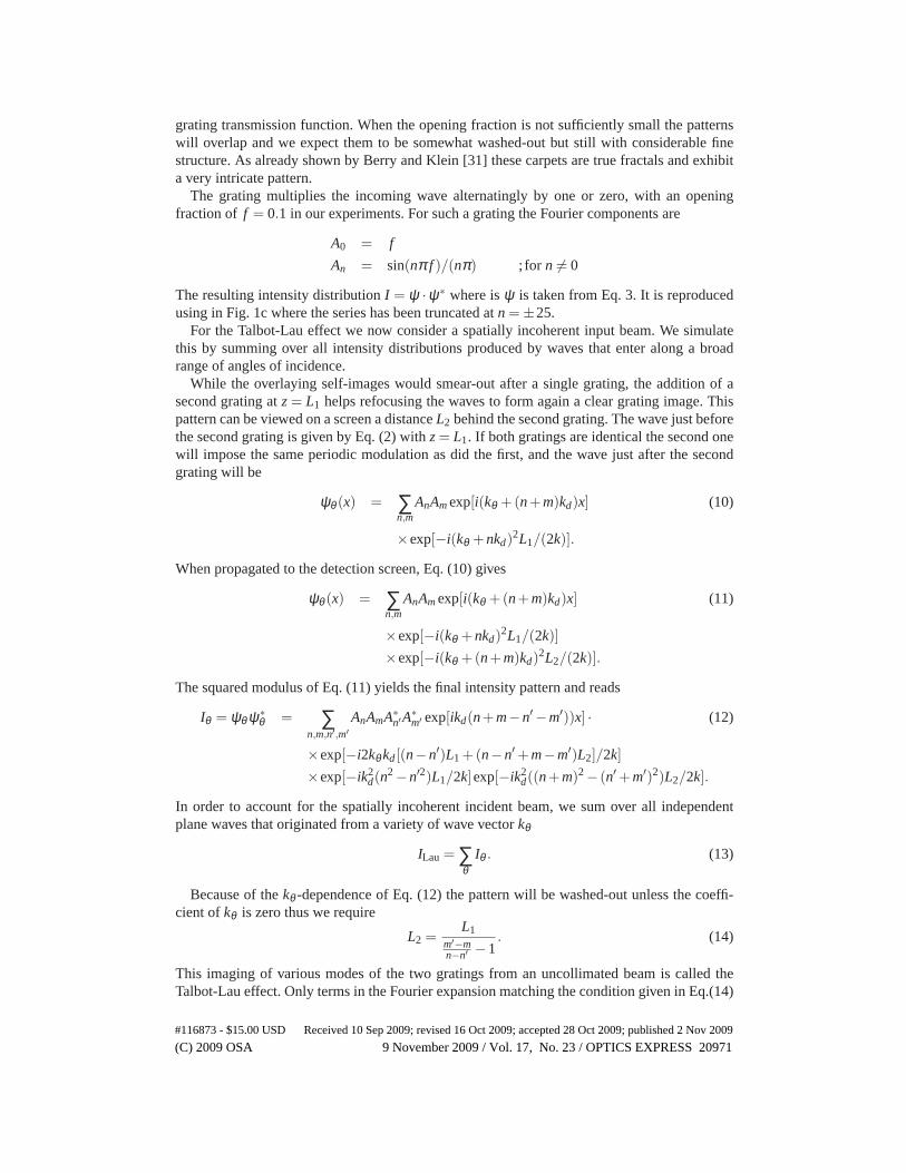
Fig. 2. (Color online) a) Talbot-Lau imaging with spatially incoherent light: A monochro-matic but spatially incoherent beam of light can be decomposed into a bundle of planewaves covering a range of incident angles. Since the laterally shifted self-images overlapnon-synchronously they wash out. Insertion of a second grating leadsto the refocusing ofthe diverging wavefronts and to the emergence of a Talbot-Lau interference pattern. b) Ex-perimental implementation with a filtered sodium lamp. The frosted glass transforms theincident light into a diffusely scattered, spatially incoherent beam. The first grating preparesspatial coherence, the second grating rephases the outgoing waves which then interfere inthe image plane of the camera lens; c) Computational simulation according toEq. (13);d) Experimental Talbot-Lau carpet. The z-axis now represents the distanceL1 between thegratings G1 and G2 which equals the distance between G2 and the imaging plane; Thenumbersm indicate where self images of themth order are observed.
#116873 - $15.00 USD Received 10 Sep 2009; revised 16 Oct 2009; accepted 28 Oct 2009; published 2 Nov 2009
(C) 2009 OSA 9 November 2009 / Vol. 17, No. 23 / OPTICS EXPRESS 20973

We first balance L1 and L2 by optimizing the sharpness of the interference pattern on theCCD chip. Ford = 200µm andλ = 589 nm the Talbot length amounts to 67.9 mm. Both thecamera and the grating are then scanned in steps∆z = 50µm to keep the distances balanced.
The result of that experiment is shown in Figure 2d which is well reproduced by the theoreti-cal model of Figure 2c withn =±20. Again we find an intricate fine structure, including rationalfractions of the Talbot image. Little differences between theory and experiment derive from theinfrared and UV lines emitted by the sodium lamp. The additional stripes that show up in theexperiment without being reproduced in the simulation are attributed to spurious wavelengthsin the UV and IR. The sodium lamp emits dominantly in the yellow spectral range (589 nm,90% of total intensity). Additional wavelengths create carpets of similar transverse structurebut with a different longitudinal scaling behavior. The second-most intense wavelength can befound at 819 nm. It produces a carpet with LT = 48.8 mm. The grating self-image in the IR canbe seen as an additional feature at 3/4 of the yellow Talbot length.
The present work thus nicely illustrates advanced wave optics in the Talbot and Lau con-figuration. Intuitive demonstrators of the kind presented here are easily realized in any opticslab and they help to derive new ideas for more complex investigations with ultra-sound, x-rays,electrons, atoms and molecules.
Acknowledgments
We would like to thank Wolfgang Schleich for stimulating discussions. This work has beensupported by the FWF within the project Z149-N16. SD acknowledges anOAD travel grantand support by the National Electronics and Computer Technology Center, National Scienceand Technology Development Agency and Industry/University Cooperative Research Center(I/UCRC) in HDD Component, the Faculty of Engineering, KhonKaen University.
#116873 - $15.00 USD Received 10 Sep 2009; revised 16 Oct 2009; accepted 28 Oct 2009; published 2 Nov 2009
(C) 2009 OSA 9 November 2009 / Vol. 17, No. 23 / OPTICS EXPRESS 20974