realsense camera r200 product datasheet
TRANSCRIPT
Document: 334616-001
Intel® RealSense™ Camera R200 Embedded Infrared Assisted Stereovision 3D Imaging System with Color Camera Product Datasheet
R200 Intel Production Part Number: MM#939143 †(X) Numeric characters representing configuration or programmed firmware at manufacturing June 2016 Revision 001
2 334616-001
You may not use or facilitate the use of this document in connection with any infringement or other legal analysis concerning Intel products described herein. You agree to grant Intel a non-exclusive, royalty-free license to any patent claim thereafter drafted which includes subject matter disclosed herein.
No license (express or implied, by estoppel or otherwise) to any intellectual property rights is granted by this document.
Intel technologies’ features and benefits depend on system configuration and may require enabled hardware, software or service activation. Learn more at Intel.com, or from the OEM or retailer.
No computer system can be absolutely secure. Intel does not assume any liability for lost or stolen data or systems or any damages resulting from such losses.
The products described may contain design defects or errors known as errata which may cause the product to deviate from published specifications. Current characterized errata are available on request.
Intel disclaims all express and implied warranties, including without limitation, the implied warranties of merchantability, fitness for a particular purpose, and non-infringement, as well as any warranty arising from course of performance, course of dealing, or usage in trade.
Intel technologies’ features and benefits depend on system configuration and may require enabled hardware, software or service activation. Learn more at intel.com, or from the OEM or retailer.
All information provided here is subject to change without notice. Contact your Intel representative to obtain the latest Intel product specifications and roadmaps.
Copies of documents which have an order number and are referenced in this document may be obtained by calling 1-800-548-4725 or visit www.intel.com/design/literature.htm.
By using this document, in addition to any agreements you have with Intel, you accept the terms set forth below.
Contact your local Intel sales office or your distributor to obtain the latest specifications and before placing your product order.
Intel, Intel RealSense and the Intel logo are trademarks of Intel Corporation in the U.S. and/or other countries.
*Other names and brands may be claimed as the property of others.
Copyright © 2016, Intel Corporation. All rights reserved.
334616-001 3
Contents 1 Description and Features .................................................................................... 9
2 Overview ......................................................................................................... 10 2.1 R200 Description ................................................................................... 10 2.2 R200 Camera Module ............................................................................. 11 2.3 Components .......................................................................................... 12 2.4 Storage and Operating Conditions ............................................................ 13 2.5 Handling Conditions ............................................................................... 13
3 Component Specification ................................................................................... 15 3.1 Imaging ................................................................................................ 15
3.1.1 Color Imaging System ............................................................... 15 3.1.2 Infrared Imaging System ........................................................... 15
3.2 Infrared Light Projection ......................................................................... 16 3.3 Activity LED .......................................................................................... 17 3.4 Temperature Sensor ............................................................................... 17 3.5 Camera Module Connector ...................................................................... 17 3.6 Other Components ................................................................................. 18
4 Functional Specification ..................................................................................... 19 4.1 Embedded 3D Imaging System ................................................................ 19 4.2 Camera Video Stream Formats ................................................................ 19
5 Firmware ......................................................................................................... 21 5.1 Firmware Update (Windows* Only) .......................................................... 21 5.2 Infrared Camera Functions ...................................................................... 21 5.3 Color Camera Functions R200 .................................................................. 21
6 System Interoperability ..................................................................................... 23 6.1 USB Composite Device ........................................................................... 23
6.1.1 Device Endpoints ...................................................................... 23 6.2 Power States ......................................................................................... 24
6.2.1 Power Consumption .................................................................. 24
7 System Integration ........................................................................................... 25 7.1 Integration Overview .............................................................................. 25 7.2 Module Stability ..................................................................................... 25 7.3 Camera Module Dimensions .................................................................... 27 7.4 Camera Module Mass .............................................................................. 27 7.5 Grounding ............................................................................................. 27 7.6 Motherboard Receptacle ......................................................................... 27 7.7 Shielding .............................................................................................. 28 7.8 Rear Cover Design Guidance ................................................................... 29
7.8.1 Transparent Cover Material ........................................................ 29 7.8.2 Gaskets ................................................................................... 30 7.8.3 Optical Isolation ....................................................................... 30 7.8.4 Dust Protection ........................................................................ 32
4 334616-001
7.9 Thermal Design Guidance ....................................................................... 32 7.9.1 Thermal Limits ......................................................................... 33 7.9.2 Thermal Management ............................................................... 34
7.10 Motherboard Routing Considerations ........................................................ 36 7.10.1 Cable TX to RX Crossover .......................................................... 37 7.10.2 Power Gate Circuit .................................................................... 37 7.10.3 Platform Specific Routing Guidance ............................................. 38 7.10.4 Motherboard Receptacle ............................................................ 38 7.10.5 High Speed Cable Assembly ....................................................... 39
8 Calibration ....................................................................................................... 41
9 System BIOS ................................................................................................... 42 9.1 UPC (USB Port Capabilities) ..................................................................... 42 9.2 PLD (Physical Device Location) ................................................................ 42
10 Packaging and Labeling ..................................................................................... 44
11 Regulatory Compliance R200 .............................................................................. 45
12 R200 Interconnect Cable Drawings ..................................................................... 47
13 R200 Connector Drawings .................................................................................. 48
14 Schematic Checklist .......................................................................................... 50
334616-001 5
List of Figures Figure 1-1. R200 Module Assembly .......................................................................................... 9 Figure 2-1. Example Color Stream .......................................................................................... 10 Figure 2-2. Example Depth Stream ......................................................................................... 11 Figure 2-3. R200 Module Form Factor ...................................................................................... 11 Figure 2-4. Component Locations (Front View) ......................................................................... 13 Figure 3-1. Infrared Projector ................................................................................................. 16 Figure 4-1. Active Stereo Technology Overview ........................................................................ 19 Figure 6-1. USB Composite Device Hardware ID ....................................................................... 23 Figure 7-1. Z Direction Module Flex Example ............................................................................ 25 Figure 7-2. Y Direction Module Flex Example ............................................................................ 26 Figure 7-3. Twist Module Flex Example .................................................................................... 26 Figure 7-4. Receptacle Ground Bar Motherboard Connections ..................................................... 28 Figure 7-5. Example IR Transmission of Acceptable Cover Material ............................................. 30 Figure 7-6. Example of Light Leakage Effects ........................................................................... 31 Figure 7-7. Example of Gasket Material Placement .................................................................... 32 Figure 7-8. Example of Separated Windows for Cover Material ................................................... 32 Figure 7-9. System Component Placement ............................................................................... 33 Figure 7-10. Module Thermal Probe Points ............................................................................... 33 Figure 7-11. Module Thermal Solution Chassis or Frame Mount .................................................. 35 Figure 7-12. Module Mounting Chassis or Frame ....................................................................... 35 Figure 7-13. Module Thermal Solution Rear Cover Mount ........................................................... 35 Figure 7-14. Module Mounting Rear Cover ............................................................................... 36 Figure 7-15. Example of Host Platform Motherboard Routing ...................................................... 37 Figure 7-16. Module Platform Power Gate Example ................................................................... 38 Figure 7-17. System Receptacle Properties .............................................................................. 38 Figure 9-1. UPC Return Package Values ................................................................................... 42 Figure 9-2. PLD System Design Considerations ......................................................................... 43 Figure 10-1. Camera Module Label .......................................................................................... 44 Figure 12-1. Cable Mechanical Drawing ................................................................................... 47 Figure 13-1. R200 Receptacle Mechanical Drawing .................................................................... 48 Figure 13-2. R200 Interconnect Plug Mechanical Drawing .......................................................... 49
6 334616-001
List of Tables Table 2-1. Component Descriptions ......................................................................................... 12 Table 2-2. Storage and Operating Conditions ........................................................................... 13 Table 2-3. Electrostatic Discharge Caution ............................................................................... 14 Table 3-1. Color Camera Properties ......................................................................................... 15 Table 3-2. Infrared Camera Properties..................................................................................... 15 Table 3-3. Infrared Projector Parameters ................................................................................. 16 Table 3-4. Module Receptacle Pinout ....................................................................................... 17 Table 3-5. Camera Module Functional Components ................................................................... 18 Table 4-1. Supported Left/Right Infrared Camera Video Stream Formats and Modes ..................... 19 Table 4-2. Supported Color Camera Video Stream Formats and Modes ........................................ 20 Table 4-3. Supported Depth Video Stream Formats and Modes ................................................... 20 Table 5-1. Left and Right IR Sensor Configuration ..................................................................... 21 Table 5-2. RGB Sensor Configuration ...................................................................................... 21 Table 6-1. USB Composite Device Endpoints ............................................................................ 23 Table 6-2. Device Power States .............................................................................................. 24 Table 6-3. Typical Power Consumption .................................................................................... 24 Table 7-1. Module Bend and Twist Limits ................................................................................. 27 Table 7-2. Component Case Temperature Limits ....................................................................... 33 Table 7-3. Component Case Temperature vs. Junction Temperature ........................................... 34 Table 7-4. Thermal Sensor vs. Laser Projector Junction Temperature .......................................... 34 Table 7-5. Copper Foil Recommendation .................................................................................. 36 Table 7-6. Heat Spreader Recommendation ............................................................................. 36 Table 7-7. Receptacle Pin Out ................................................................................................ 38 Table 7-8. Receptacle Characteristics ...................................................................................... 39 Table 7-9. Plug Characteristics ............................................................................................... 39 Table 7-10. Cable Assembly Specification ................................................................................ 39 Table 7-11. Cable Assembly Interconnect Properties ................................................................. 40 Table 9-1. UPC Elements ....................................................................................................... 42 Table 9-2. PLD Elements ........................................................................................................ 42 Table 9-3. PLD Return Package Values .................................................................................... 43 Table 10-1. Scan Code Fields ................................................................................................. 44 Table 12-1. Cable Part Numbers ............................................................................................. 47 Table 14-1. Motherboard Connector Signals ............................................................................. 50 Table 14-2. USB_RX Motherboard Signals ................................................................................ 50 Table 14-3. USB_TX Motherboard Signals ................................................................................ 50 Table 14-4. Power Signals ..................................................................................................... 51
334616-001 7
Additional References
Reference document Document Number
Intel® RealSense™ Camera R200 3D CAD Files 334617-001
8 334616-001
Revision History
Revision Number
Description Revision Date
001 • Initial Release June 2016
§ §
Description and Features
334616-001 9
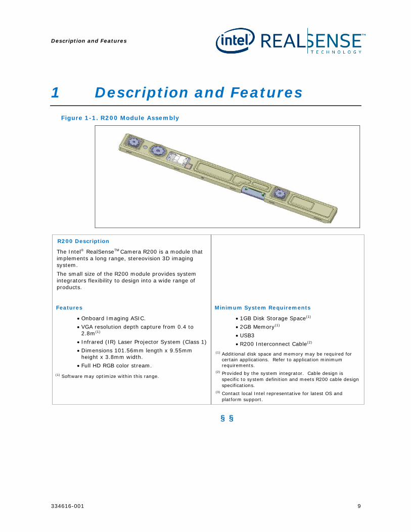
1 Description and Features Figure 1-1. R200 Module Assembly
R200 Description
The Intel® RealSenseTM Camera R200 is a module that implements a long range, stereovision 3D imaging system. The small size of the R200 module provides system integrators flexibility to design into a wide range of products.
Features
• Onboard Imaging ASIC. • VGA resolution depth capture from 0.4 to
2.8m(1) • Infrared (IR) Laser Projector System (Class 1) • Dimensions 101.56mm length x 9.55mm
height x 3.8mm width. • Full HD RGB color stream.
(1) Software may optimize within this range.
Minimum System Requirements
• 1GB Disk Storage Space(1) • 2GB Memory(1) • USB3 • R200 Interconnect Cable(2)
(1) Additional disk space and memory may be required for certain applications. Refer to application minimum requirements.
(2) Provided by the system integrator. Cable design is specific to system definition and meets R200 cable design specifications.
(3) Contact local Intel representative for latest OS and platform support.
§ §
Overview
10 334616-001
2 Overview
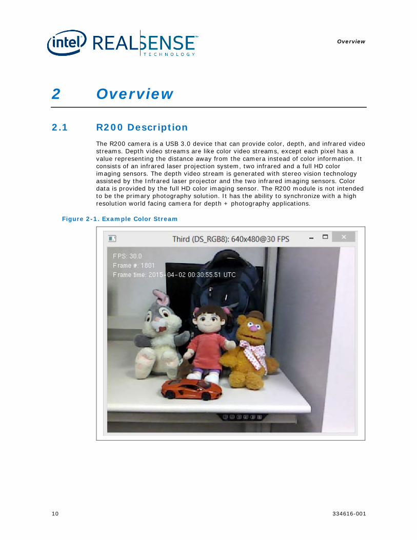
2.1 R200 Description The R200 camera is a USB 3.0 device that can provide color, depth, and infrared video streams. Depth video streams are like color video streams, except each pixel has a value representing the distance away from the camera instead of color information. It consists of an infrared laser projection system, two infrared and a full HD color imaging sensors. The depth video stream is generated with stereo vision technology assisted by the Infrared laser projector and the two infrared imaging sensors. Color data is provided by the full HD color imaging sensor. The R200 module is not intended to be the primary photography solution. It has the ability to synchronize with a high resolution world facing camera for depth + photography applications.
Figure 2-1. Example Color Stream
Overview
334616-001 11
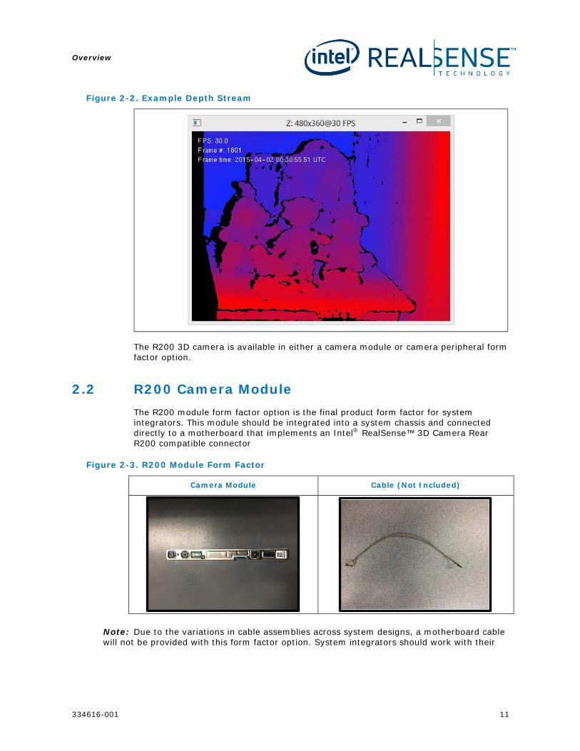
Figure 2-2. Example Depth Stream
The R200 3D camera is available in either a camera module or camera peripheral form factor option.
2.2 R200 Camera Module The R200 module form factor option is the final product form factor for system integrators. This module should be integrated into a system chassis and connected directly to a motherboard that implements an Intel® RealSense™ 3D Camera Rear R200 compatible connector
Figure 2-3. R200 Module Form Factor
Camera Module Cable (Not Included)
Note: Due to the variations in cable assemblies across system designs, a motherboard cable will not be provided with this form factor option. System integrators should work with their
Overview
12 334616-001
respective cable suppliers to manufacture a cable according to the guidance provided in this document.
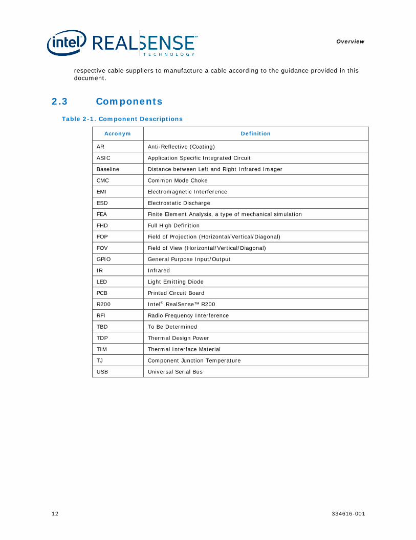
2.3 Components Table 2-1. Component Descriptions
Acronym Definition
AR Anti-Reflective (Coating)
ASIC Application Specific Integrated Circuit
Baseline Distance between Left and Right Infrared Imager
CMC Common Mode Choke
EMI Electromagnetic Interference
ESD Electrostatic Discharge
FEA Finite Element Analysis, a type of mechanical simulation
FHD Full High Definition
FOP Field of Projection (Horizontal/Vertical/Diagonal)
FOV Field of View (Horizontal/Vertical/Diagonal)
GPIO General Purpose Input/Output
IR Infrared
LED Light Emitting Diode
PCB Printed Circuit Board
R200 Intel® RealSense™ R200
RFI Radio Frequency Interference
TBD To Be Determined
TDP Thermal Design Power
TIM Thermal Interface Material
TJ Component Junction Temperature
USB Universal Serial Bus
Overview
334616-001 13
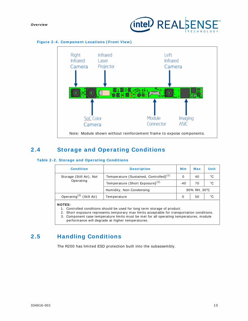
Figure 2-4. Component Locations (Front View)
Note: Module shown without reinforcement frame to expose components.
2.4 Storage and Operating Conditions Table 2-2. Storage and Operating Conditions
Condition Description Min Max Unit
Storage (Still Air), Not Operating
Temperature (Sustained, Controlled)(1) 0 40 oC
Temperature (Short Exposure)(2) -40 70 oC
Humidity, Non-Condensing 90% RH, 30oC
Operating(3) (Still Air) Temperature 0 50 oC
NOTES: 1. Controlled conditions should be used for long term storage of product. 2. Short exposure represents temporary max limits acceptable for transportation conditions. 3. Component case temperature limits must be met for all operating temperatures, module
performance will degrade at higher temperatures.
2.5 Handling Conditions The R200 has limited ESD protection built into the subassembly.

Overview
14 334616-001
Table 2-3. Electrostatic Discharge Caution
To provide a consistent ESD protection level during R200 system assembly and rework, it is recommended that the JEDEC JESD625-A requirements standard be incorporated into the ESD environment controls.
§ §
Component Specification
334616-001 15
3 Component Specification
3.1 Imaging
3.1.1 Color Imaging System
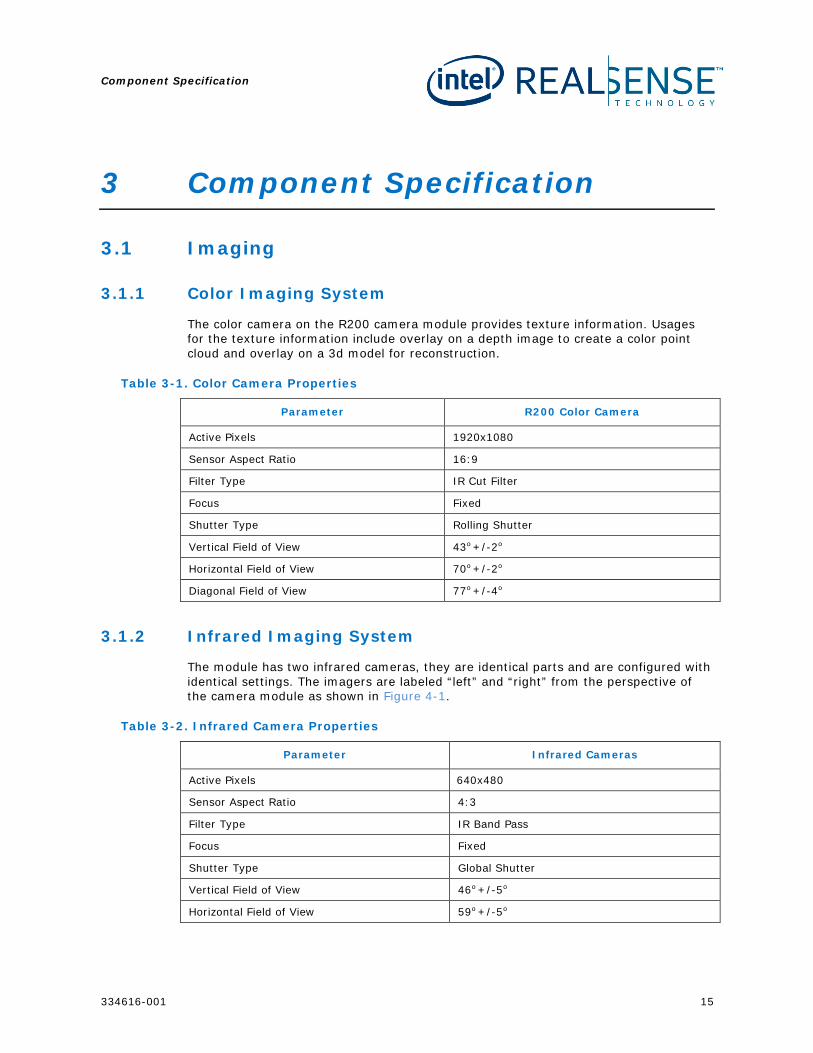
The color camera on the R200 camera module provides texture information. Usages for the texture information include overlay on a depth image to create a color point cloud and overlay on a 3d model for reconstruction.
Table 3-1. Color Camera Properties
Parameter R200 Color Camera
Active Pixels 1920x1080
Sensor Aspect Ratio 16:9
Filter Type IR Cut Filter
Focus Fixed
Shutter Type Rolling Shutter
Vertical Field of View 43o +/-2o
Horizontal Field of View 70o +/-2o
Diagonal Field of View 77o +/-4o
3.1.2 Infrared Imaging System
The module has two infrared cameras, they are identical parts and are configured with identical settings. The imagers are labeled “left” and “right” from the perspective of the camera module as shown in Figure 4-1.
Table 3-2. Infrared Camera Properties
Parameter Infrared Cameras
Active Pixels 640x480
Sensor Aspect Ratio 4:3
Filter Type IR Band Pass
Focus Fixed
Shutter Type Global Shutter
Vertical Field of View 46o +/-5o
Horizontal Field of View 59o +/-5o
Component Specification
16 334616-001
Parameter Infrared Cameras
Diagonal Field of View 70o+/-4.5o
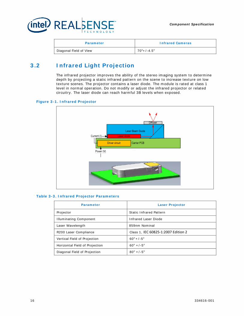
3.2 Infrared Light Projection The infrared projector improves the ability of the stereo imaging system to determine depth by projecting a static infrared pattern on the scene to increase texture on low texture scenes. The projector contains a laser diode. The module is rated at class 1 level in normal operation. Do not modify or adjust the infrared projector or related circuitry. The laser diode can reach harmful 3B levels when exposed.
Figure 3-1. Infrared Projector
Table 3-3. Infrared Projector Parameters
Parameter Laser Projector
Projector Static Infrared Pattern
Illuminating Component Infrared Laser Diode
Laser Wavelength 859nm Nominal
R200 Laser Compliance Class 1, IEC 60825-1:2007 Edition 2
Vertical Field of Projection 60o +/-5o
Horizontal Field of Projection 60o +/-5o
Diagonal Field of Projection 80o +/-5o
Component Specification
334616-001 17
3.3 Activity LED The camera module integrates one activity LED to notify the user if either the infrared camera or color camera is streaming data.
3.4 Temperature Sensor The module is equipped with a thermal sensor that is used for laser safety. The software library provides access to the thermal sensor but it is not intended to be used by applications outside of development environments.
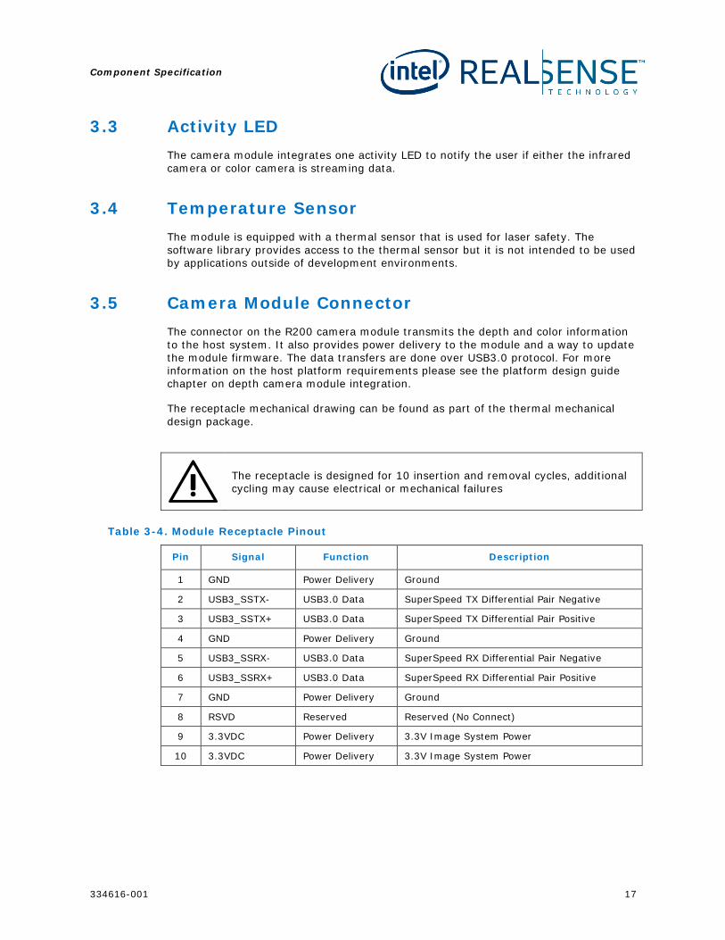
3.5 Camera Module Connector The connector on the R200 camera module transmits the depth and color information to the host system. It also provides power delivery to the module and a way to update the module firmware. The data transfers are done over USB3.0 protocol. For more information on the host platform requirements please see the platform design guide chapter on depth camera module integration.
The receptacle mechanical drawing can be found as part of the thermal mechanical design package.
The receptacle is designed for 10 insertion and removal cycles, additional cycling may cause electrical or mechanical failures
Table 3-4. Module Receptacle Pinout
Pin Signal Function Description
1 GND Power Delivery Ground
2 USB3_SSTX- USB3.0 Data SuperSpeed TX Differential Pair Negative
3 USB3_SSTX+ USB3.0 Data SuperSpeed TX Differential Pair Positive
4 GND Power Delivery Ground
5 USB3_SSRX- USB3.0 Data SuperSpeed RX Differential Pair Negative
6 USB3_SSRX+ USB3.0 Data SuperSpeed RX Differential Pair Positive
7 GND Power Delivery Ground
8 RSVD Reserved Reserved (No Connect)
9 3.3VDC Power Delivery 3.3V Image System Power
10 3.3VDC Power Delivery 3.3V Image System Power
Component Specification
18 334616-001
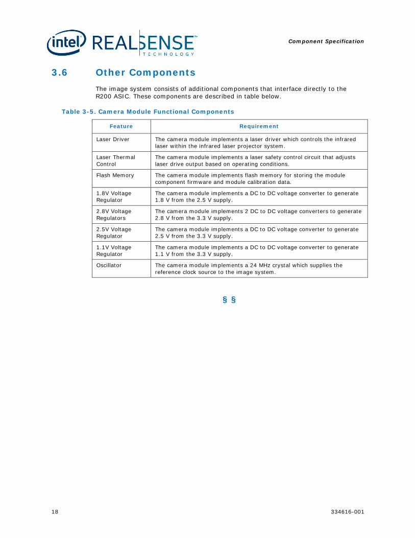
3.6 Other Components The image system consists of additional components that interface directly to the R200 ASIC. These components are described in table below.
Table 3-5. Camera Module Functional Components
Feature Requirement
Laser Driver The camera module implements a laser driver which controls the infrared laser within the infrared laser projector system.
Laser Thermal Control
The camera module implements a laser safety control circuit that adjusts laser drive output based on operating conditions.
Flash Memory The camera module implements flash memory for storing the module component firmware and module calibration data.
1.8V Voltage Regulator
The camera module implements a DC to DC voltage converter to generate 1.8 V from the 2.5 V supply.
2.8V Voltage Regulators
The camera module implements 2 DC to DC voltage converters to generate 2.8 V from the 3.3 V supply.
2.5V Voltage Regulator
The camera module implements a DC to DC voltage converter to generate 2.5 V from the 3.3 V supply.
1.1V Voltage Regulator
The camera module implements a DC to DC voltage converter to generate 1.1 V from the 3.3 V supply.
Oscillator The camera module implements a 24 MHz crystal which supplies the reference clock source to the image system.
§ §
Functional Specification
334616-001 19
4 Functional Specification
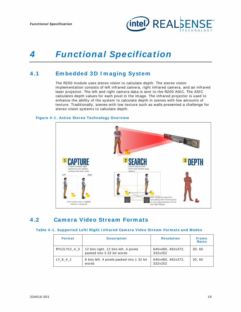
4.1 Embedded 3D Imaging System The R200 module uses stereo vision to calculate depth. The stereo vision implementation consists of left infrared camera, right infrared camera, and an infrared laser projector. The left and right camera data is sent to the R200 ASIC. The ASIC calculates depth values for each pixel in the image. The infrared projector is used to enhance the ability of the system to calculate depth in scenes with low amounts of texture. Traditionally, scenes with low texture such as walls presented a challenge for stereo vision systems to calculate depth.
Figure 4-1. Active Stereo Technology Overview
4.2 Camera Video Stream Formats Table 4-1. Supported Left/Right Infrared Camera Video Stream Formats and Modes
Format Description Resolution Frame Rates
RY12LY12_4_3 12 bits right, 12 bits left, 4 pixels packed into 3 32 bit words
640x480, 492x372, 332x252
30, 60
LY_8_4_1 8 bits left, 4 pixels packed into 1 32 bit words
640x480, 492x372, 332x252
30, 60
Functional Specification
20 334616-001
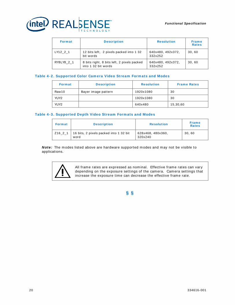
Format Description Resolution Frame Rates
LY12_2_1 12 bits left, 2 pixels packed into 1 32 bit words
640x480, 492x372, 332x252
30, 60
RY8LY8_2_1 8 bits right, 8 bits left, 2 pixels packed into 1 32 bit words
640x480, 492x372, 332x252
30, 60
Table 4-2. Supported Color Camera Video Stream Formats and Modes
Format Description Resolution Frame Rates
Raw10 Bayer image pattern 1920x1080 30
YUY2 1920x1080 30
YUY2 640x480 15,30,60
Table 4-3. Supported Depth Video Stream Formats and Modes
Format Description Resolution Frame Rates
Z16_2_1 16 bits, 2 pixels packed into 1 32 bit word
628x468, 480x360, 320x240
30, 60
Note: The modes listed above are hardware supported modes and may not be visible to applications.
All frame rates are expressed as nominal. Effective frame rates can vary depending on the exposure settings of the camera. Camera settings that increase the exposure time can decrease the effective frame rate.
§ §
Firmware
334616-001 21
5 Firmware
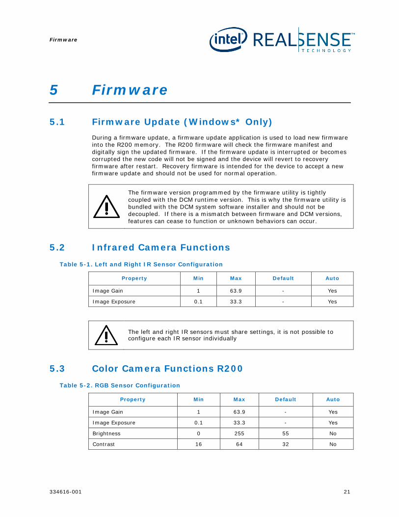
5.1 Firmware Update (Windows* Only) During a firmware update, a firmware update application is used to load new firmware into the R200 memory. The R200 firmware will check the firmware manifest and digitally sign the updated firmware. If the firmware update is interrupted or becomes corrupted the new code will not be signed and the device will revert to recovery firmware after restart. Recovery firmware is intended for the device to accept a new firmware update and should not be used for normal operation.
The firmware version programmed by the firmware utility is tightly coupled with the DCM runtime version. This is why the firmware utility is bundled with the DCM system software installer and should not be decoupled. If there is a mismatch between firmware and DCM versions, features can cease to function or unknown behaviors can occur.
5.2 Infrared Camera Functions
Table 5-1. Left and Right IR Sensor Configuration
Property Min Max Default Auto
Image Gain 1 63.9 - Yes
Image Exposure 0.1 33.3 - Yes
The left and right IR sensors must share settings, it is not possible to configure each IR sensor individually
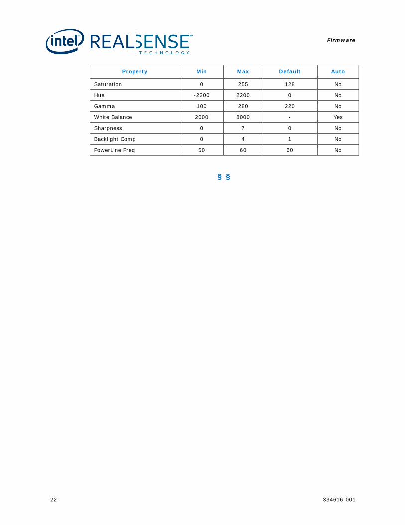
5.3 Color Camera Functions R200 Table 5-2. RGB Sensor Configuration
Property Min Max Default Auto
Image Gain 1 63.9 - Yes
Image Exposure 0.1 33.3 - Yes
Brightness 0 255 55 No
Contrast 16 64 32 No
Firmware
22 334616-001
Property Min Max Default Auto
Saturation 0 255 128 No
Hue -2200 2200 0 No
Gamma 100 280 220 No
White Balance 2000 8000 - Yes
Sharpness 0 7 0 No
Backlight Comp 0 4 1 No
PowerLine Freq 50 60 60 No
§ §
System Interoperability
334616-001 23
6 System Interoperability
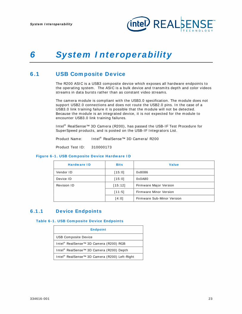
6.1 USB Composite Device The R200 ASIC is a USB3 composite device which exposes all hardware endpoints to the operating system. The ASIC is a bulk device and transmits depth and color videos streams in data bursts rather than as constant video streams.
The camera module is compliant with the USB3.0 specification. The module does not support USB2.0 connections and does not route the USB2.0 pins. In the case of a USB3.0 link training failure it is possible that the module will not be detected. Because the module is an integrated device, it is not expected for the module to encounter USB3.0 link training failures.
Intel® RealSense™ 3D Camera (R200), has passed the USB-IF Test Procedure for SuperSpeed products, and is posted on the USB-IF Integrators List.
Product Name: Intel® RealSense™ 3D Camera/ R200
Product Test ID: 310000173
Figure 6-1. USB Composite Device Hardware ID
Hardware ID Bits Value
Vendor ID [15:0] 0x8086
Device ID [15:0] 0x0A80
Revision ID [15:12] Firmware Major Version
[11:5] Firmware Minor Version
[4:0] Firmware Sub-Minor Version
6.1.1 Device Endpoints
Table 6-1. USB Composite Device Endpoints
Endpoint
USB Composite Device
Intel® RealSense™ 3D Camera (R200) RGB
Intel® RealSense™ 3D Camera (R200) Depth
Intel® RealSense™ 3D Camera (R200) Left-Right
System Interoperability
24 334616-001
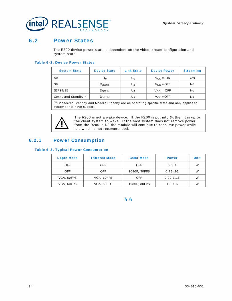
6.2 Power States The R200 device power state is dependent on the video stream configuration and system state.
Table 6-2. Device Power States
System State Device State Link State Device Power Streaming
S0 D0 U0 VCC = ON Yes
S0 D3Cold U3 VCC =OFF No
S3/S4/S5 D3Cold U3 VCC = OFF No
Connected Standby(1) D3Cold U3 VCC =OFF No (1) Connected Standby and Modern Standby are an operating specific state and only applies to systems that have support.
The R200 is not a wake device. If the R200 is put into D3 then it is up to the client system to wake. If the host system does not remove power from the R200 in D3 the module will continue to consume power while idle which is not recommended.
6.2.1 Power Consumption
Table 6-3. Typical Power Consumption
Depth Mode Infrared Mode Color Mode Power Unit
OFF OFF OFF 0.334 W
OFF OFF 1080P, 30FPS 0.75-.92 W
VGA, 60FPS VGA, 60FPS OFF 0.99-1.15 W
VGA, 60FPS VGA, 60FPS 1080P, 30FPS 1.3-1.6 W
§ §
System Integration
334616-001 25
7 System Integration
7.1 Integration Overview The small size of the R200 module provides system integrators flexibility to design into a wide range of products. This section describes how to integrate the module into a system chassis.
7.2 Module Stability It is critical that the R200 module does not experience flex during system integration or during use after integration. The module arrives calibrated and ready for installation into a system. Micron level flexing of the module can render the calibration incorrect and will result in poor performance or nonfunctional depth data. It is important for system designers to isolate the module from any chassis flex the system may encounter. Micron levels of module flex can disrupt the depth stream. While the module has reinforcement housing, the housing is not intended to counter loads from chassis flex. The primary function of the housing is to prevent loss of calibration from handling and operating environments.
There are three types of flex the module can encounter independently or in combination: Y, Z, and twisting. The impacts to performance of each flex type are discussed in this section.
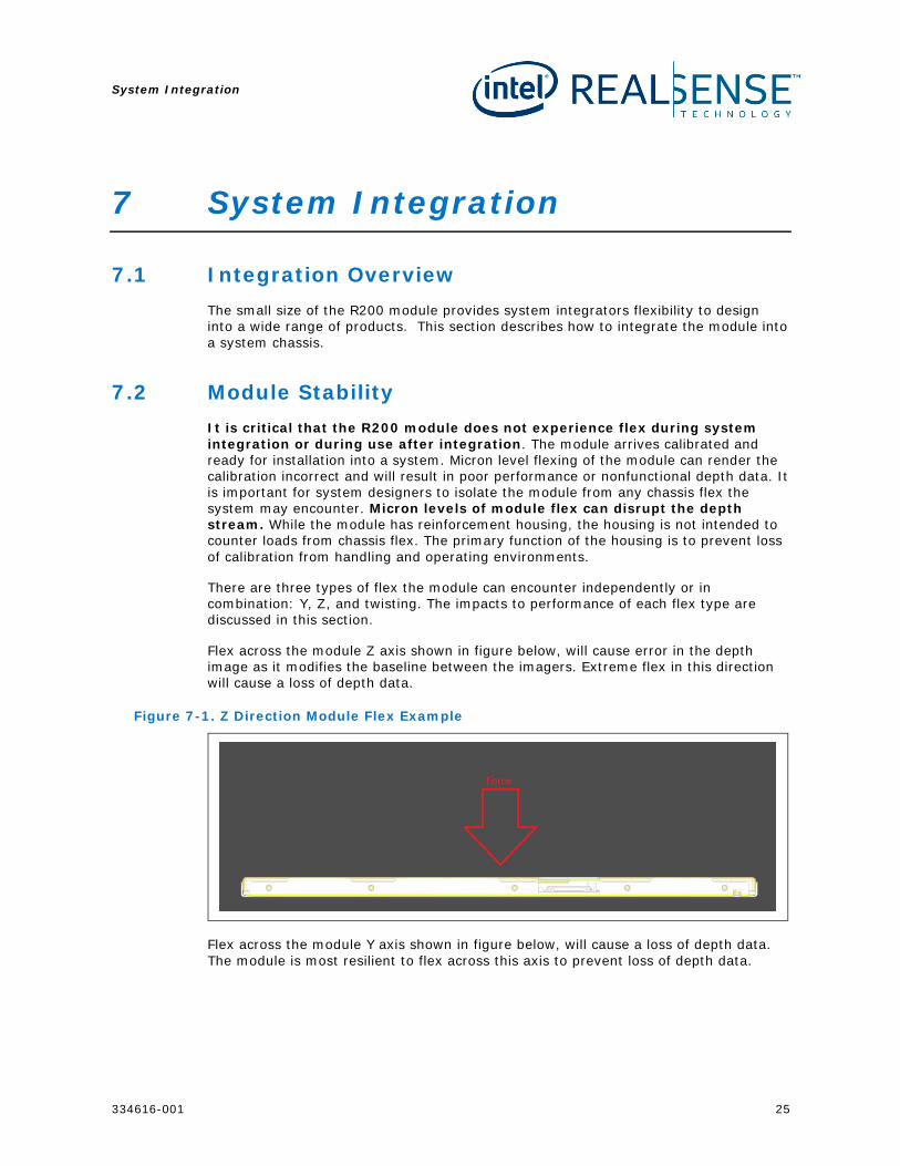
Flex across the module Z axis shown in figure below, will cause error in the depth image as it modifies the baseline between the imagers. Extreme flex in this direction will cause a loss of depth data.
Figure 7-1. Z Direction Module Flex Example
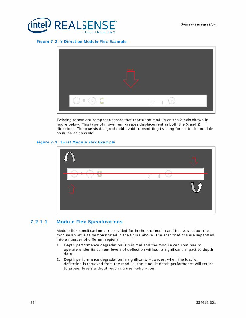
Flex across the module Y axis shown in figure below, will cause a loss of depth data. The module is most resilient to flex across this axis to prevent loss of depth data.
System Integration
26 334616-001
Figure 7-2. Y Direction Module Flex Example
Twisting forces are composite forces that rotate the module on the X axis shown in figure below. This type of movement creates displacement in both the X and Z directions. The chassis design should avoid transmitting twisting forces to the module as much as possible.
Figure 7-3. Twist Module Flex Example
7.2.1.1 Module Flex Specifications
Module flex specifications are provided for in the z-direction and for twist about the module’s x-axis as demonstrated in the figure above. The specifications are separated into a number of different regions: 1. Depth performance degradation is minimal and the module can continue to
operate under its current levels of deflection without a significant impact to depth data.
2. Depth performance degradation is significant. However, when the load or deflection is removed from the module, the module depth performance will return to proper levels without requiring user calibration.
System Integration
334616-001 27
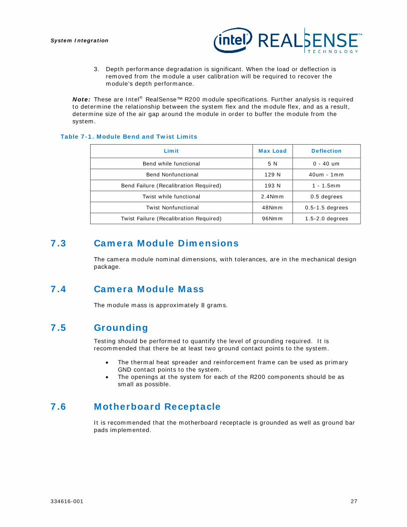
3. Depth performance degradation is significant. When the load or deflection is removed from the module a user calibration will be required to recover the module’s depth performance.
Note: These are Intel® RealSense™ R200 module specifications. Further analysis is required to determine the relationship between the system flex and the module flex, and as a result, determine size of the air gap around the module in order to buffer the module from the system.
Table 7-1. Module Bend and Twist Limits
Limit Max Load Deflection
Bend while functional 5 N 0 - 40 um
Bend Nonfunctional 129 N 40um - 1mm
Bend Failure (Recalibration Required) 193 N 1 - 1.5mm
Twist while functional 2.4Nmm 0.5 degrees
Twist Nonfunctional 48Nmm 0.5-1.5 degrees
Twist Failure (Recalibration Required) 96Nmm 1.5-2.0 degrees
7.3 Camera Module Dimensions The camera module nominal dimensions, with tolerances, are in the mechanical design package.
7.4 Camera Module Mass The module mass is approximately 8 grams.
7.5 Grounding Testing should be performed to quantify the level of grounding required. It is recommended that there be at least two ground contact points to the system.
• The thermal heat spreader and reinforcement frame can be used as primary GND contact points to the system.
• The openings at the system for each of the R200 components should be as small as possible.
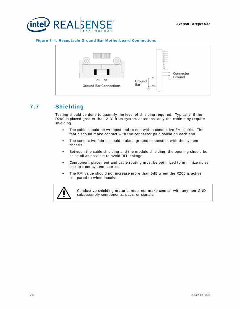
7.6 Motherboard Receptacle It is recommended that the motherboard receptacle is grounded as well as ground bar pads implemented.
System Integration
28 334616-001
Figure 7-4. Receptacle Ground Bar Motherboard Connections
7.7 Shielding Testing should be done to quantify the level of shielding required. Typically, if the R200 is placed greater than 2-3” from system antennas, only the cable may require shielding.
• The cable should be wrapped end to end with a conductive EMI fabric. The fabric should make contact with the connector plug shield on each end.
• The conductive fabric should make a ground connection with the system chassis.
• Between the cable shielding and the module shielding, the opening should be as small as possible to avoid RFI leakage.
• Component placement and cable routing must be optimized to minimize noise pickup from system sources.
• The RFI value should not increase more than 5dB when the R200 is active compared to when inactive.
Conductive shielding material must not make contact with any non-GND subassembly components, pads, or signals.
System Integration
334616-001 29
7.8 Rear Cover Design Guidance In addition to any thermal heat spreaders, the rear cover design must take into consideration the openings for the R200 camera, projector, and LED. The openings should be designed so that they provide protection from dirt and damage but also accommodate the following considerations.
• Maximize effective field of view of the cameras and field of projection of the projector
• Minimize air gap distance between the bezel surface and the front of the imaging module components. This is done to minimize the size of the holes in the rear cover required.
• Employ gasket material and separate cover material windows to isolate the IR laser projector output and prevent reflections off the cover material back into the system chassis.
The R200 computer aided design model (part of mechanical design package) includes the lens field of view projection profiles for each component. It is recommended to use the model along with a platform chassis model to minimize the cover hole diameters.
7.8.1 Transparent Cover Material
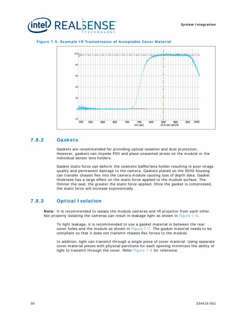
It is recommended to use a transparent cover material over in the rear cover holes to protect the camera module and prevent dirt from entering the system chassis. For the IR projector and IR cameras, the material must have a 98% or higher transmission rate in the 854 nm to 864 nm range. Anti-reflective coatings can help increase the IR transmission of transparent material. Most designs will require an AR coating on both sides of the cover material to reach 98% IR light transmission, using material with lower than 98% transmission can result in poor depth performance. Because the camera performance is limited by IR light from the projector indoors, a transparent cover material that reduces IR light transmission will decrease the working range of the camera.
System Integration
30 334616-001
Figure 7-5. Example IR Transmission of Acceptable Cover Material
7.8.2 Gaskets
Gaskets are recommended for providing optical isolation and dust protection. However, gaskets can impede FOV and place unwanted stress on the module or the individual sensor lens holders.
Gasket static force can deform the cosmetic baffle/lens holder resulting in poor image quality and permanent damage to the camera. Gaskets placed on the R200 housing can transfer chassis flex into the camera module causing loss of depth data. Gasket thickness has a large effect on the static force applied to the module surface. The thinner the seal, the greater the static force applied. Once the gasket is compressed, the static force will increase exponentially.
7.8.3 Optical Isolation
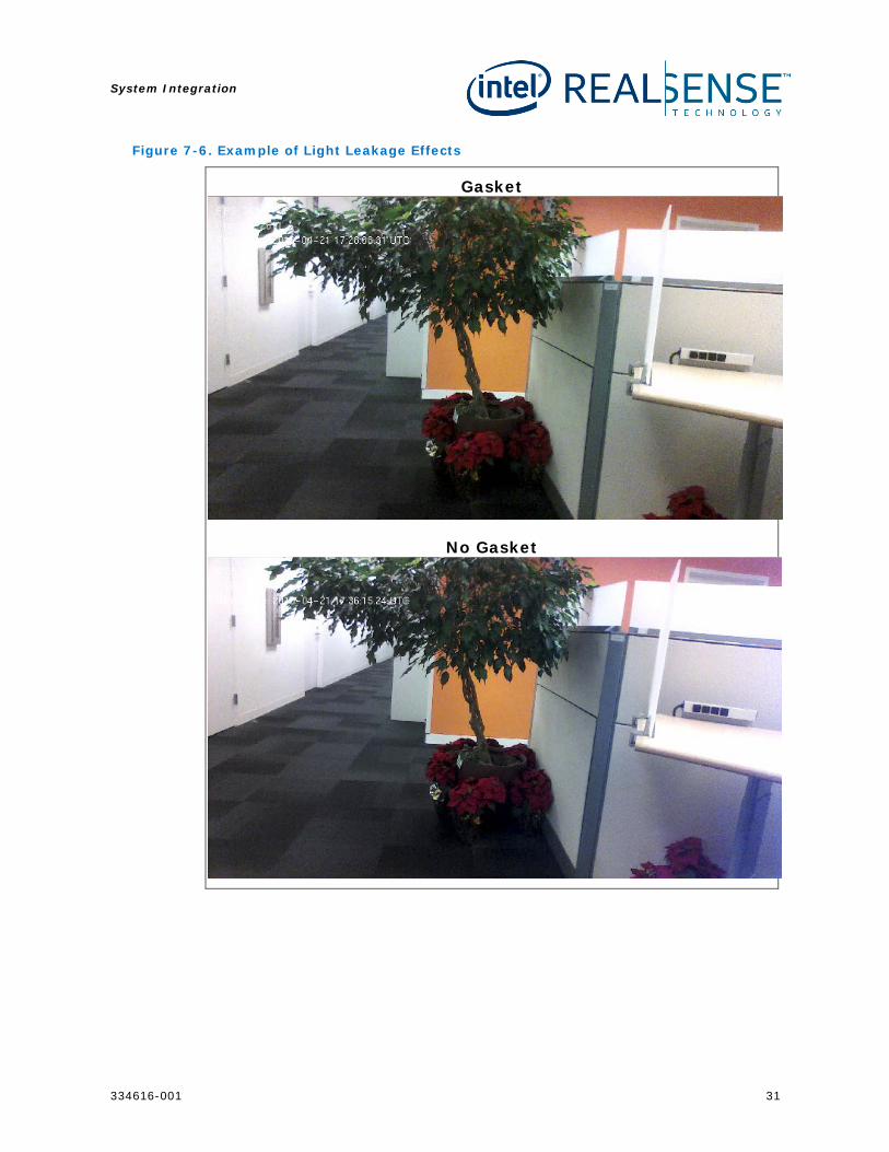
Note: It is recommended to isolate the module cameras and IR projector from each other. Not properly isolating the cameras can result in leakage light as shown in Figure 7-6.
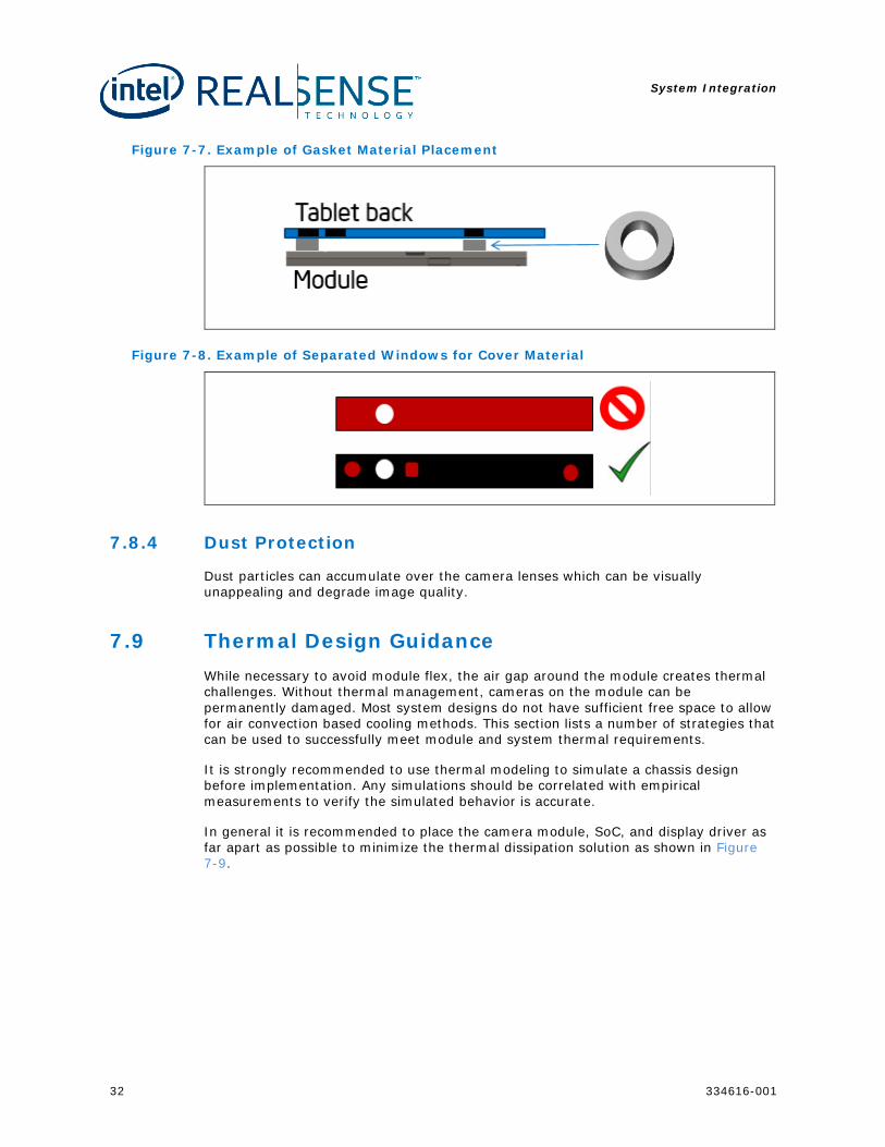
To light leakage, it is recommended to use a gasket material in between the rear cover holes and the module as shown in Figure 7-7. The gasket material needs to be compliant so that it does not transmit chassis flex forces to the module.
In addition, light can transmit through a single piece of cover material. Using separate cover material pieces with physical partitions for each opening minimizes the ability of light to transmit through the cover. Refer Figure 7-8 for reference.
System Integration
334616-001 31
Figure 7-6. Example of Light Leakage Effects
Gasket
No Gasket
System Integration
32 334616-001
Figure 7-7. Example of Gasket Material Placement
Figure 7-8. Example of Separated Windows for Cover Material
7.8.4 Dust Protection
Dust particles can accumulate over the camera lenses which can be visually unappealing and degrade image quality.
7.9 Thermal Design Guidance While necessary to avoid module flex, the air gap around the module creates thermal challenges. Without thermal management, cameras on the module can be permanently damaged. Most system designs do not have sufficient free space to allow for air convection based cooling methods. This section lists a number of strategies that can be used to successfully meet module and system thermal requirements.
It is strongly recommended to use thermal modeling to simulate a chassis design before implementation. Any simulations should be correlated with empirical measurements to verify the simulated behavior is accurate.
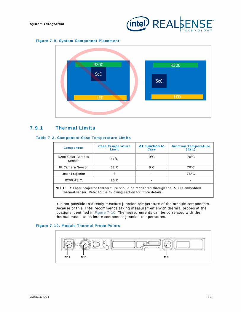
In general it is recommended to place the camera module, SoC, and display driver as far apart as possible to minimize the thermal dissipation solution as shown in Figure 7-9.
System Integration
334616-001 33
Figure 7-9. System Component Placement
7.9.1 Thermal Limits
Table 7-2. Component Case Temperature Limits
Component Case Temperature Limit
ΔT Junction to Case
Junction Temperature (Est.)
R200 Color Camera Sensor 61oC 9oC 70oC
IR Camera Sensor 62oC 8oC 70oC
Laser Projector † - 75°C
R200 ASIC 95oC - -
NOTE: † Laser projector temperature should be monitored through the R200’s embedded thermal sensor. Refer to the following section for more details.
It is not possible to directly measure junction temperature of the module components. Because of this, Intel recommends taking measurements with thermal probes at the locations identified in Figure 7-10. The measurements can be correlated with the thermal model to estimate component junction temperatures.
Figure 7-10. Module Thermal Probe Points
System Integration
34 334616-001
Table 7-3. Component Case Temperature vs. Junction Temperature
Point Component Junction Temp (Est.)
TC1 Right IR Camera Surface Case Temp +8oC
TC2 RGB Camera Surface Case Temp +9oC
TC3 Left IR Camera Surface Case Temp +8oC
There is a single embedded thermal sensor on the R200 module. This thermal sensor has been correlated to the Laser Projector’s junction temperature. It should not be used to correlate junction temperatures of any of the other components on the R200 module.
Table 7-4. Thermal Sensor vs. Laser Projector Junction Temperature
Item Component Junction Temp (Est.)
Embedded Thermal Sensor Laser Projector Thermal Sensor +9 ± 3°C
7.9.2 Thermal Management
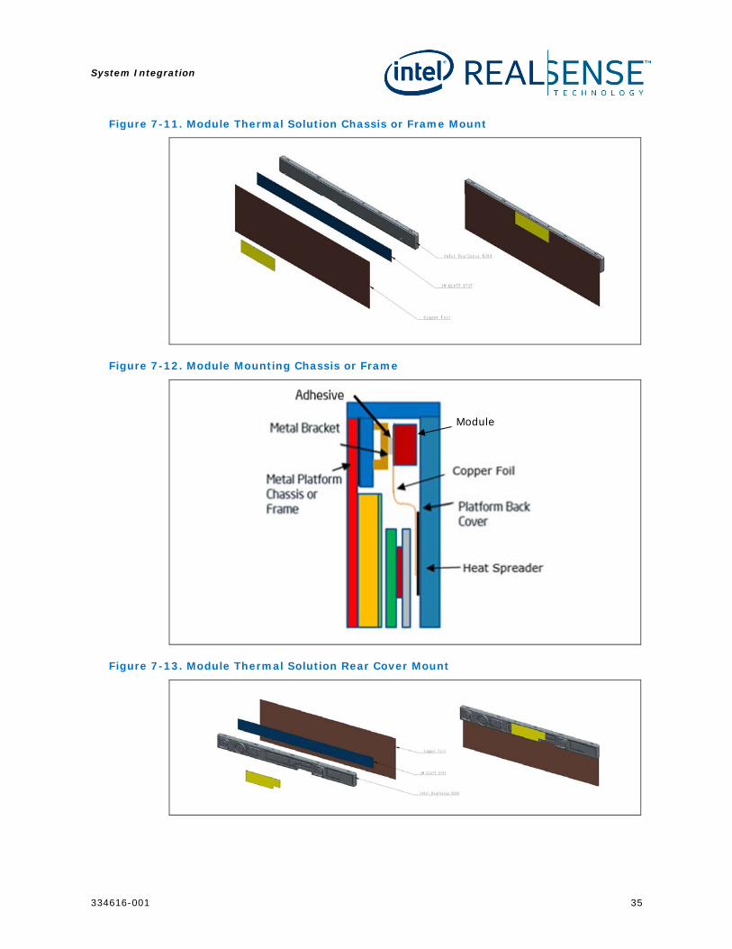
The recommended strategy for thermal management is to use thin copper foil to transfer heat away from the module. The use of flexible foil maintains the isolation of the module from the system chassis as the foil will not apply mechanical loading on the module. The copper foil is adhered to the back side of the module and transfers heat to a graphite heat spreader on the system chassis rear cover or over the LCD panel heat spreader. If the LCD panel heat spreader is used, care must be taken to avoid overheating the LCD panel.
It is recommended to mount the module on a thermally conductive chassis component. The thermal properties of the adhesive should be considered when choosing an adhesive to attach the camera module to the chassis. The bracket should contact metal in the chassis to dissipate heat and provide an ESD ground path. Alternatively, the copper foil can provide an ESD ground path and other non-electrically conductive adhesives can be used. While a longer bracket would help thermal performance, the bracket should be no more than 25mm long to keep the module isolated from chassis flex.
System Integration
334616-001 35
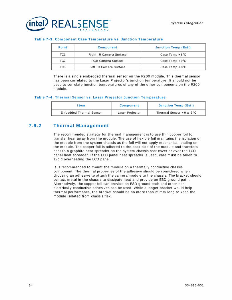
Figure 7-11. Module Thermal Solution Chassis or Frame Mount
Figure 7-12. Module Mounting Chassis or Frame
Figure 7-13. Module Thermal Solution Rear Cover Mount
Module
System Integration
36 334616-001
Figure 7-14. Module Mounting Rear Cover
Table 7-5. Copper Foil Recommendation
Detail Notes
Material Copper
Thickness 0.2mm
Width 110mm (entire back side of module)
Min Overlap with Module 9.5mm
Table 7-6. Heat Spreader Recommendation
Detail Notes
Material Graphite
Thickness 0.2mm
Minimum Surface Area 260x80mm^2
Min Overlap With Copper Foil 10mm
7.10 Motherboard Routing Considerations The imaging module requires a dedicated XHCI USB3 port. A USB hub must not be implemented between the imaging module and XHCI USB3 port to ensure highest possible bandwidth. The routing topology is specific to the platform. If the platform the R200 is being integrated is not listed below, please contact your Intel representative for support details.
Adhesive Camera Module
System Integration
334616-001 37
7.10.1 Cable TX to RX Crossover
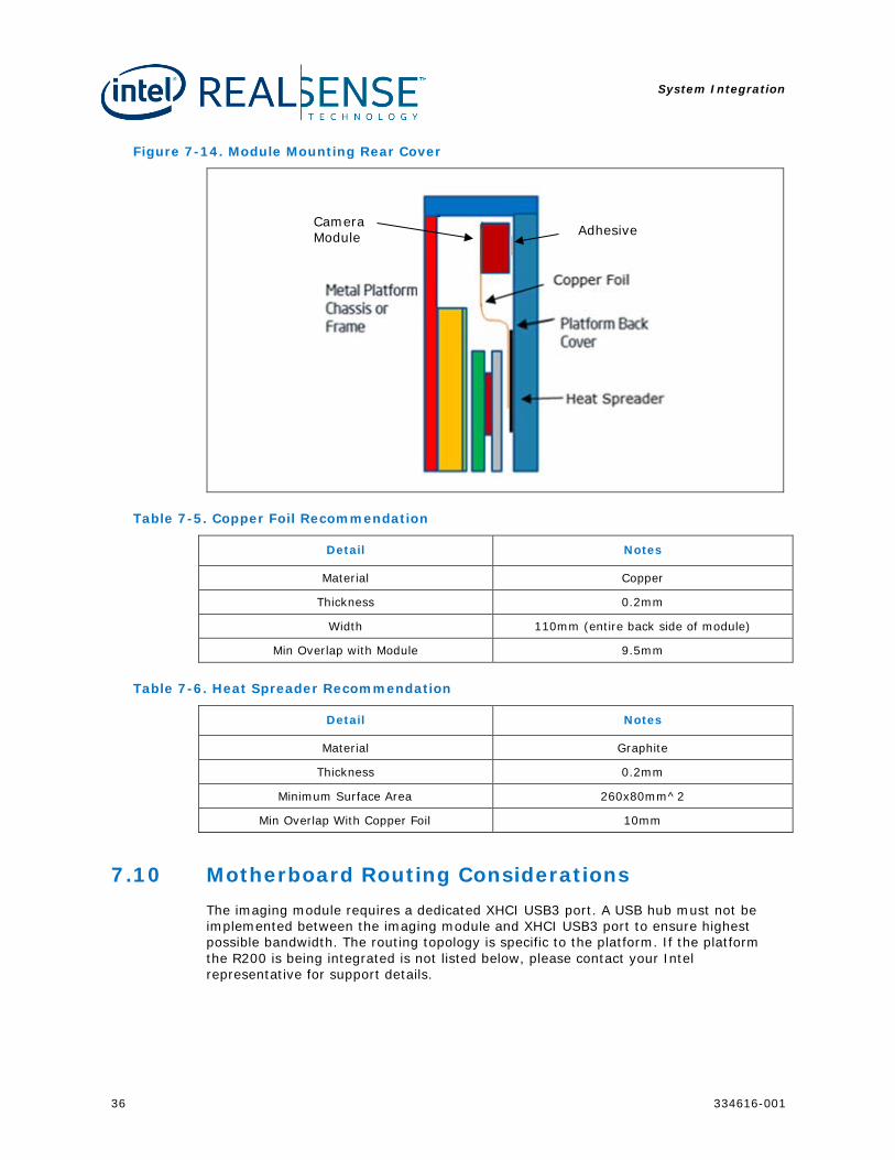
Standard USB3.0 requires the cable to cross the host TX to the device RX and the host RX to the device TX. For the R200 module, it is recommended not to cross over the signals in the cable to allow cable wiring to be flat and as thin as possible. The modules do not cross over the TX and RX signals, it is necessary to do this on the platform motherboard.
Figure 7-15. Example of Host Platform Motherboard Routing
7.10.2 Power Gate Circuit
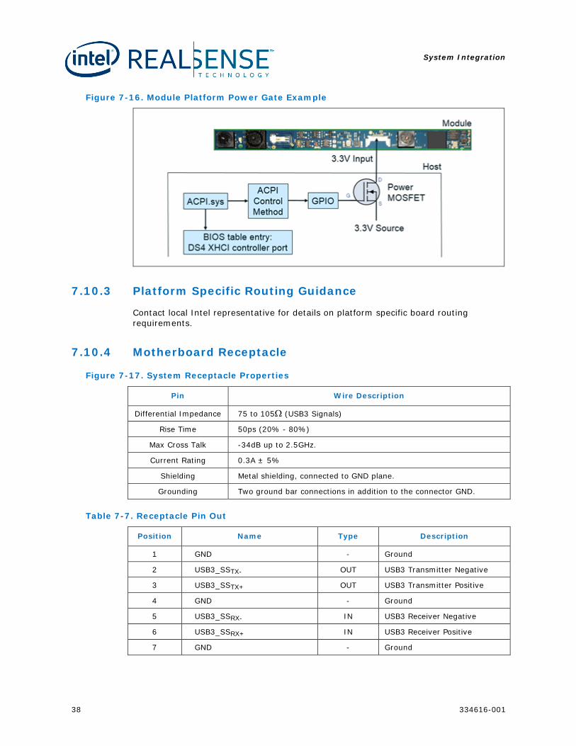
It is required that the host platform is able to gate power to the R200 module. The power gate must be controllable via an ACPI and BIOS controllable GPIO. It is recommended for the implementation to be able to vary the delay from when the GPIO is asserted to when the ACPI code notifies the OS the device is powered.
System Integration
38 334616-001
Figure 7-16. Module Platform Power Gate Example
7.10.3 Platform Specific Routing Guidance
Contact local Intel representative for details on platform specific board routing requirements.
7.10.4 Motherboard Receptacle
Figure 7-17. System Receptacle Properties
Pin Wire Description
Differential Impedance 75 to 105Ω (USB3 Signals)
Rise Time 50ps (20% - 80%)
Max Cross Talk -34dB up to 2.5GHz.
Current Rating 0.3A ± 5%
Shielding Metal shielding, connected to GND plane.
Grounding Two ground bar connections in addition to the connector GND.
Table 7-7. Receptacle Pin Out
Position Name Type Description
1 GND - Ground
2 USB3_SSTX- OUT USB3 Transmitter Negative
3 USB3_SSTX+ OUT USB3 Transmitter Positive
4 GND - Ground
5 USB3_SSRX- IN USB3 Receiver Negative
6 USB3_SSRX+ IN USB3 Receiver Positive
7 GND - Ground
System Integration
334616-001 39
Position Name Type Description
8 RSVD - RSVD (No Connect)
9 VCC - Supply Voltage, Connect to 3.3V
10 VCC - Supply Voltage, Connect to 3.3V
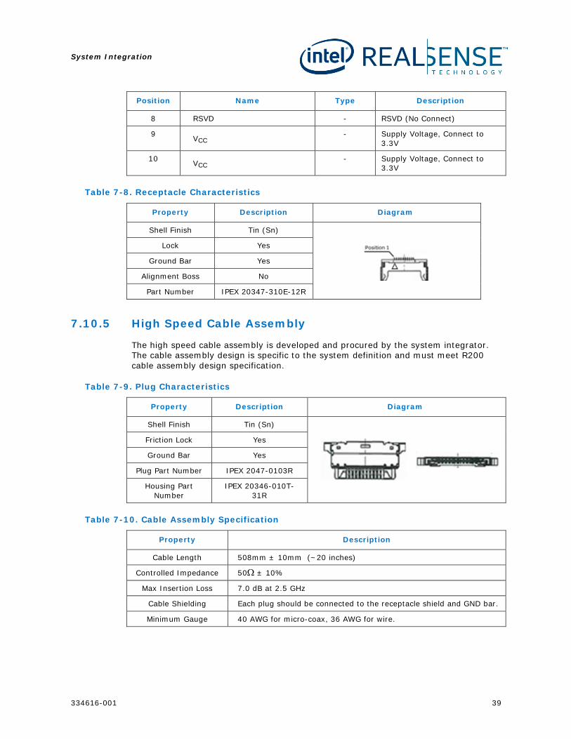
Table 7-8. Receptacle Characteristics
Property Description Diagram
Shell Finish Tin (Sn)
Lock Yes
Ground Bar Yes
Alignment Boss No
Part Number IPEX 20347-310E-12R
7.10.5 High Speed Cable Assembly
The high speed cable assembly is developed and procured by the system integrator. The cable assembly design is specific to the system definition and must meet R200 cable assembly design specification.
Table 7-9. Plug Characteristics
Property Description Diagram
Shell Finish Tin (Sn)
Friction Lock Yes
Ground Bar Yes
Plug Part Number IPEX 2047-0103R
Housing Part Number
IPEX 20346-010T-31R
Table 7-10. Cable Assembly Specification
Property Description
Cable Length 508mm ± 10mm (~20 inches)
Controlled Impedance 50Ω ± 10%
Max Insertion Loss 7.0 dB at 2.5 GHz
Cable Shielding Each plug should be connected to the receptacle shield and GND bar.
Minimum Gauge 40 AWG for micro-coax, 36 AWG for wire.
System Integration
40 334616-001
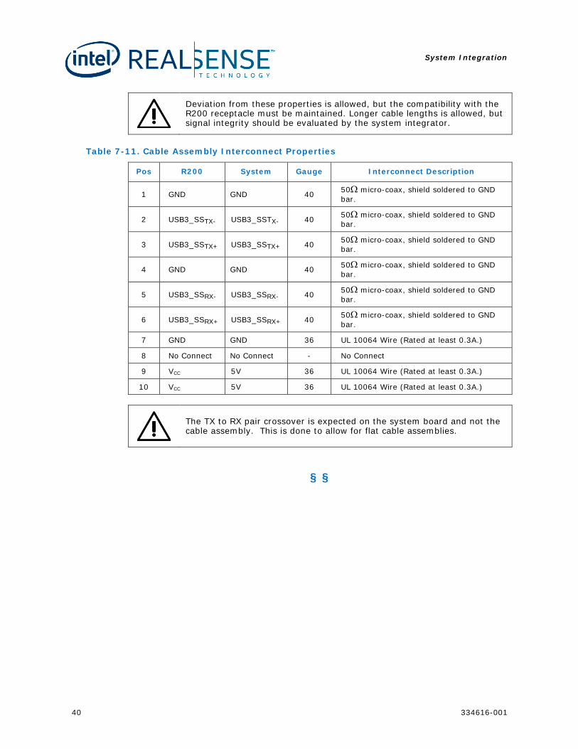
Deviation from these properties is allowed, but the compatibility with the R200 receptacle must be maintained. Longer cable lengths is allowed, but signal integrity should be evaluated by the system integrator.
Table 7-11. Cable Assembly Interconnect Properties
Pos R200 System Gauge Interconnect Description
1 GND GND 40 50Ω micro-coax, shield soldered to GND bar.
2 USB3_SSTX- USB3_SSTX- 40 50Ω micro-coax, shield soldered to GND bar.
3 USB3_SSTX+ USB3_SSTX+ 40 50Ω micro-coax, shield soldered to GND bar.
4 GND GND 40 50Ω micro-coax, shield soldered to GND bar.
5 USB3_SSRX- USB3_SSRX- 40 50Ω micro-coax, shield soldered to GND bar.
6 USB3_SSRX+ USB3_SSRX+ 40 50Ω micro-coax, shield soldered to GND bar.
7 GND GND 36 UL 10064 Wire (Rated at least 0.3A.)
8 No Connect No Connect - No Connect
9 VCC 5V 36 UL 10064 Wire (Rated at least 0.3A.)
10 VCC 5V 36 UL 10064 Wire (Rated at least 0.3A.)
The TX to RX pair crossover is expected on the system board and not the cable assembly. This is done to allow for flat cable assemblies.
§ §
Calibration
334616-001 41
8 Calibration The R200 camera module requires calibration if it is distorted during the assembly process or by environmental conditions in the field. For details on high volume calibration solutions, contact local Intel representative.
§§
System BIOS
42 334616-001
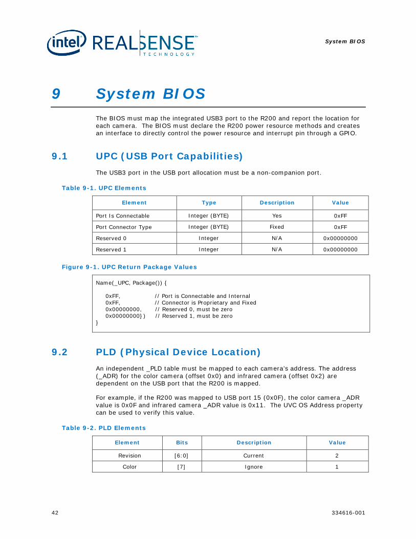
9 System BIOS The BIOS must map the integrated USB3 port to the R200 and report the location for each camera. The BIOS must declare the R200 power resource methods and creates an interface to directly control the power resource and interrupt pin through a GPIO.
9.1 UPC (USB Port Capabilities) The USB3 port in the USB port allocation must be a non-companion port.
Table 9-1. UPC Elements
Element Type Description Value
Port Is Connectable Integer (BYTE) Yes 0xFF
Port Connector Type Integer (BYTE) Fixed 0xFF
Reserved 0 Integer N/A 0x00000000
Reserved 1 Integer N/A 0x00000000
Figure 9-1. UPC Return Package Values
Name(_UPC, Package()) 0xFF, // Port is Connectable and Internal 0xFF, // Connector is Proprietary and Fixed 0x00000000, // Reserved 0, must be zero 0x00000000) // Reserved 1, must be zero
9.2 PLD (Physical Device Location) An independent _PLD table must be mapped to each camera’s address. The address (_ADR) for the color camera (offset 0x0) and infrared camera (offset 0x2) are dependent on the USB port that the R200 is mapped.
For example, if the R200 was mapped to USB port 15 (0x0F), the color camera _ADR value is 0x0F and infrared camera _ADR value is 0x11. The UVC OS Address property can be used to verify this value.
Table 9-2. PLD Elements
Element Bits Description Value
Revision [6:0] Current 2
Color [7] Ignore 1
System BIOS
334616-001 43
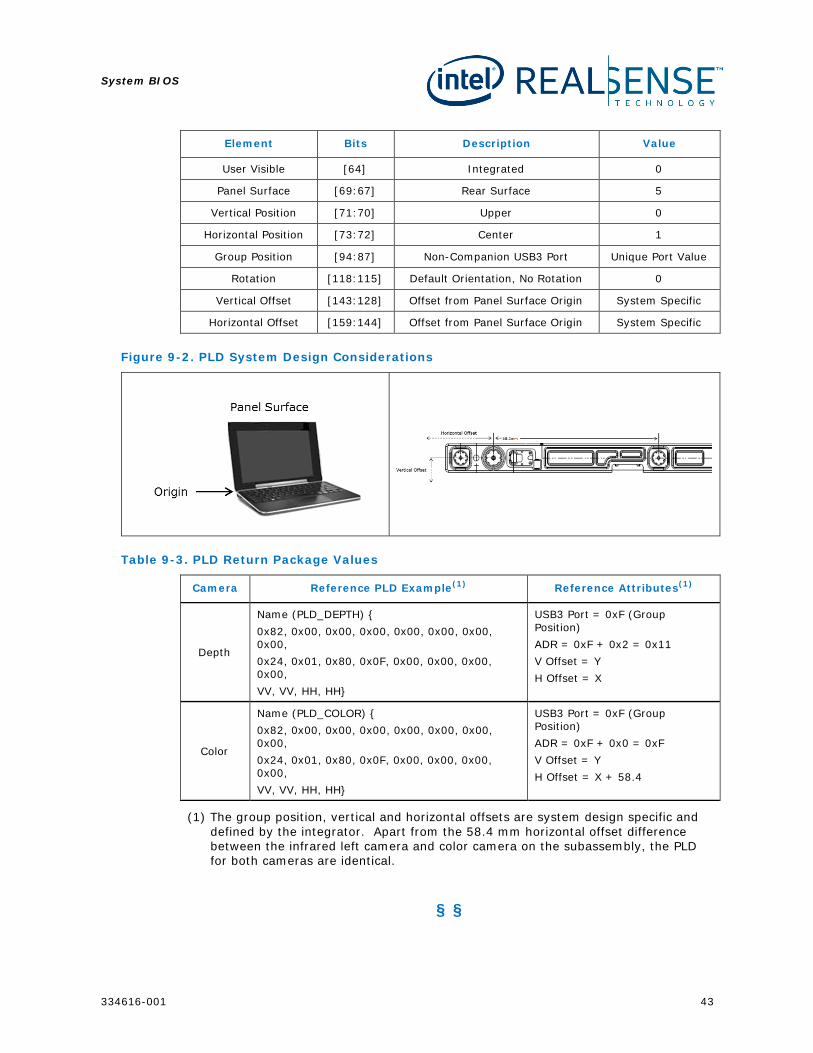
Element Bits Description Value
User Visible [64] Integrated 0
Panel Surface [69:67] Rear Surface 5
Vertical Position [71:70] Upper 0
Horizontal Position [73:72] Center 1
Group Position [94:87] Non-Companion USB3 Port Unique Port Value
Rotation [118:115] Default Orientation, No Rotation 0
Vertical Offset [143:128] Offset from Panel Surface Origin System Specific
Horizontal Offset [159:144] Offset from Panel Surface Origin System Specific
Figure 9-2. PLD System Design Considerations
Table 9-3. PLD Return Package Values
Camera Reference PLD Example(1) Reference Attributes(1)
Depth
Name (PLD_DEPTH) 0x82, 0x00, 0x00, 0x00, 0x00, 0x00, 0x00, 0x00, 0x24, 0x01, 0x80, 0x0F, 0x00, 0x00, 0x00, 0x00, VV, VV, HH, HH
USB3 Port = 0xF (Group Position) ADR = 0xF + 0x2 = 0x11 V Offset = Y H Offset = X
Color
Name (PLD_COLOR) 0x82, 0x00, 0x00, 0x00, 0x00, 0x00, 0x00, 0x00, 0x24, 0x01, 0x80, 0x0F, 0x00, 0x00, 0x00, 0x00, VV, VV, HH, HH
USB3 Port = 0xF (Group Position) ADR = 0xF + 0x0 = 0xF V Offset = Y H Offset = X + 58.4
(1) The group position, vertical and horizontal offsets are system design specific and defined by the integrator. Apart from the 58.4 mm horizontal offset difference between the infrared left camera and color camera on the subassembly, the PLD for both cameras are identical.
§ §
Packaging and Labeling
44 334616-001
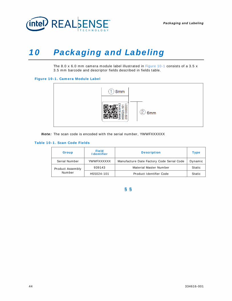
10 Packaging and Labeling The 8.0 x 6.0 mm camera module label illustrated in Figure 10-1 consists of a 3.5 x 3.5 mm barcode and descriptor fields described in fields table.
Figure 10-1. Camera Module Label
Note: The scan code is encoded with the serial number, YWWFXXXXXX
Table 10-1. Scan Code Fields
Group Field Identifier Description Type
Serial Number YWWFXXXXXX Manufacture Date Factory Code Serial Code Dynamic
Product Assembly Number
939143 Material Master Number Static
H55024-101 Product Identifier Code Static
§ §
Regulatory Compliance R200
334616-001 45
11 Regulatory Compliance R200
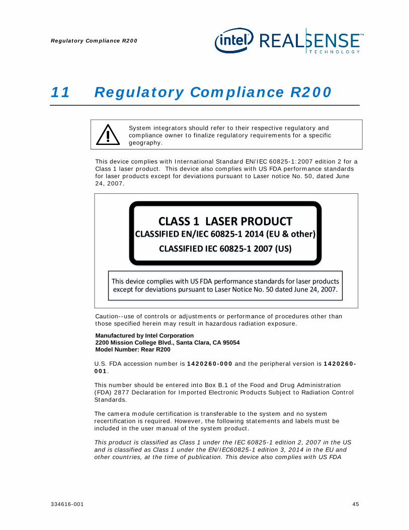
System integrators should refer to their respective regulatory and compliance owner to finalize regulatory requirements for a specific geography.
This device complies with International Standard EN/IEC 60825-1:2007 edition 2 for a Class 1 laser product. This device also complies with US FDA performance standards for laser products except for deviations pursuant to Laser notice No. 50, dated June 24, 2007.
CLASS 1 LASER PRODUCTCLASSIFIED EN/IEC 60825-1 2014 (EU & other)
CLASSIFIED IEC 60825-1 2007 (US)
This device complies with US FDA performance standards for laser products except for deviations pursuant to Laser Notice No. 50 dated June 24, 2007.
Caution--use of controls or adjustments or performance of procedures other than those specified herein may result in hazardous radiation exposure.
Manufactured by Intel Corporation 2200 Mission College Blvd., Santa Clara, CA 95054 Model Number: Rear R200
U.S. FDA accession number is 1420260-000 and the peripheral version is 1420260-001.
This number should be entered into Box B.1 of the Food and Drug Administration (FDA) 2877 Declaration for Imported Electronic Products Subject to Radiation Control Standards.
The camera module certification is transferable to the system and no system recertification is required. However, the following statements and labels must be included in the user manual of the system product.
This product is classified as Class 1 under the IEC 60825-1 edition 2, 2007 in the US and is classified as Class 1 under the EN/IEC60825-1 edition 3, 2014 in the EU and other countries, at the time of publication. This device also complies with US FDA
Regulatory Compliance R200
46 334616-001
performance standards for laser products except for deviations pursuant to Laser notice No. 50, dated June 24, 2007.
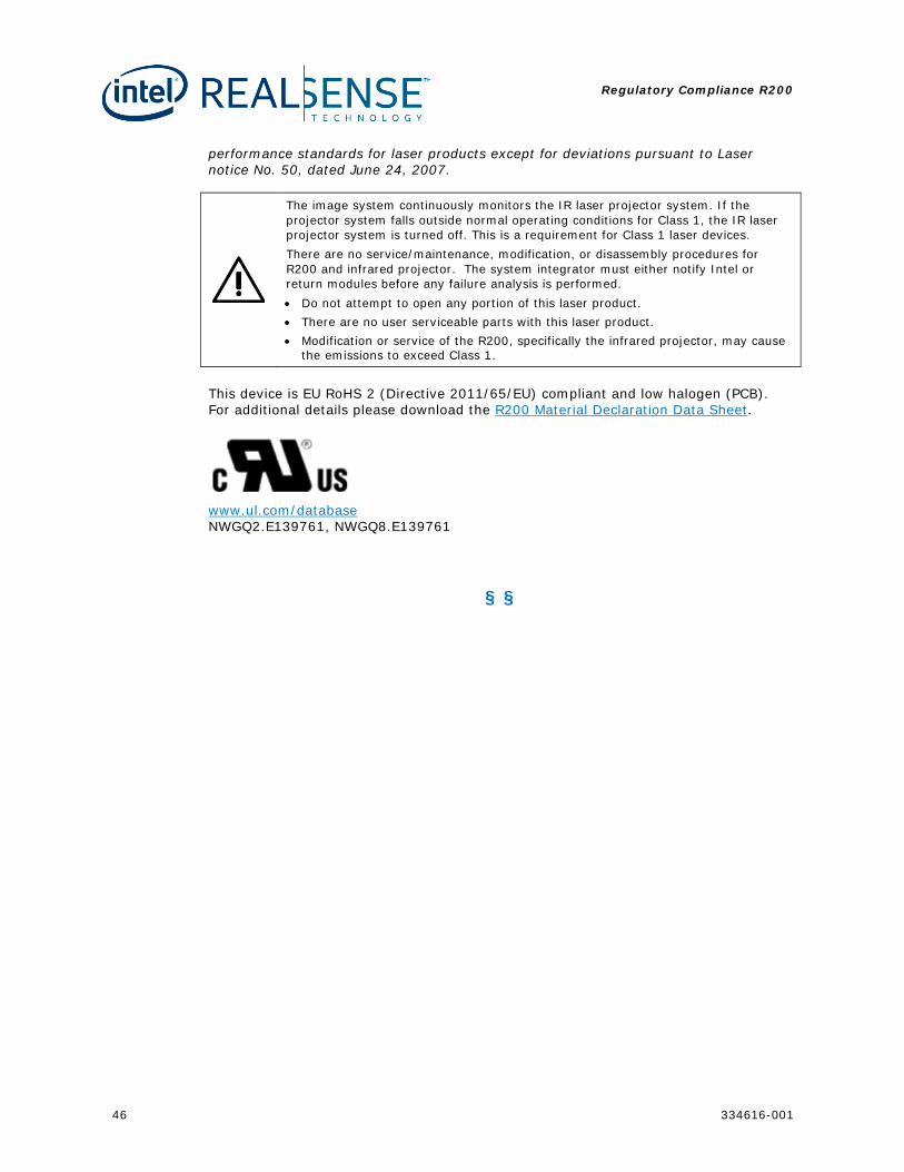
The image system continuously monitors the IR laser projector system. If the projector system falls outside normal operating conditions for Class 1, the IR laser projector system is turned off. This is a requirement for Class 1 laser devices. There are no service/maintenance, modification, or disassembly procedures for R200 and infrared projector. The system integrator must either notify Intel or return modules before any failure analysis is performed. • Do not attempt to open any portion of this laser product. • There are no user serviceable parts with this laser product. • Modification or service of the R200, specifically the infrared projector, may cause
the emissions to exceed Class 1.
This device is EU RoHS 2 (Directive 2011/65/EU) compliant and low halogen (PCB). For additional details please download the R200 Material Declaration Data Sheet.
www.ul.com/database NWGQ2.E139761, NWGQ8.E139761
§ §
R200 Interconnect Cable Drawings
334616-001 47
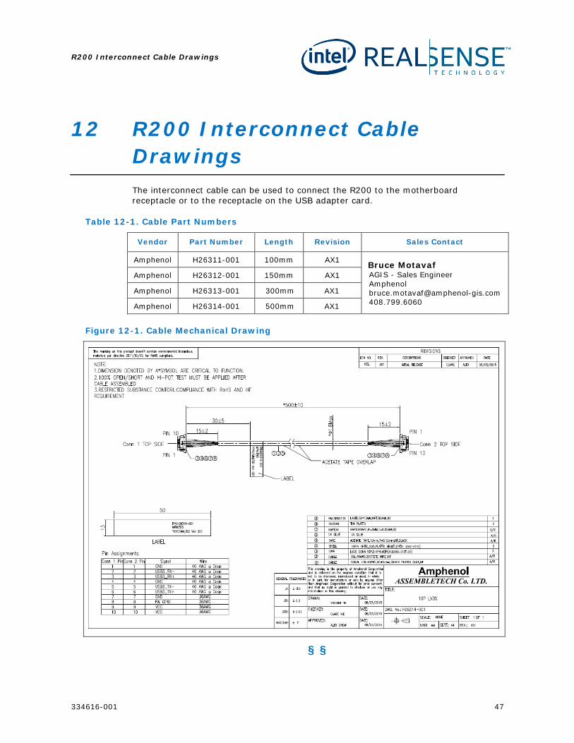
12 R200 Interconnect Cable Drawings The interconnect cable can be used to connect the R200 to the motherboard receptacle or to the receptacle on the USB adapter card.
Table 12-1. Cable Part Numbers
Vendor Part Number Length Revision Sales Contact
Amphenol H26311-001 100mm AX1 Bruce Motavaf AGIS - Sales Engineer Amphenol [email protected] 408.799.6060
Amphenol H26312-001 150mm AX1
Amphenol H26313-001 300mm AX1
Amphenol H26314-001 500mm AX1
Figure 12-1. Cable Mechanical Drawing
§ §
R200 Connector Drawings
48 334616-001
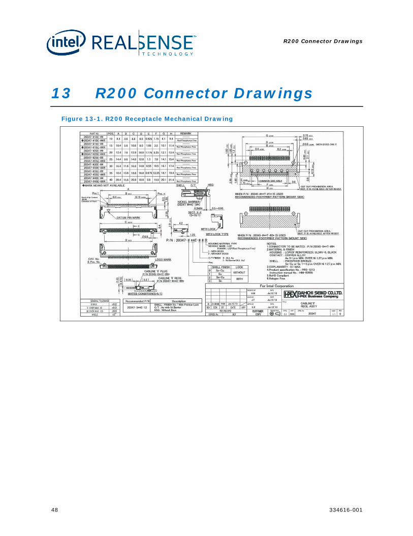
13 R200 Connector Drawings Figure 13-1. R200 Receptacle Mechanical Drawing
R200 Connector Drawings
334616-001 49
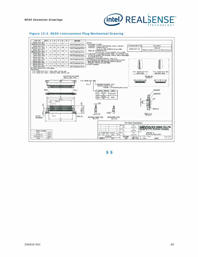
Figure 13-2. R200 Interconnect Plug Mechanical Drawing
§ §
Schematic Checklist
50 334616-001
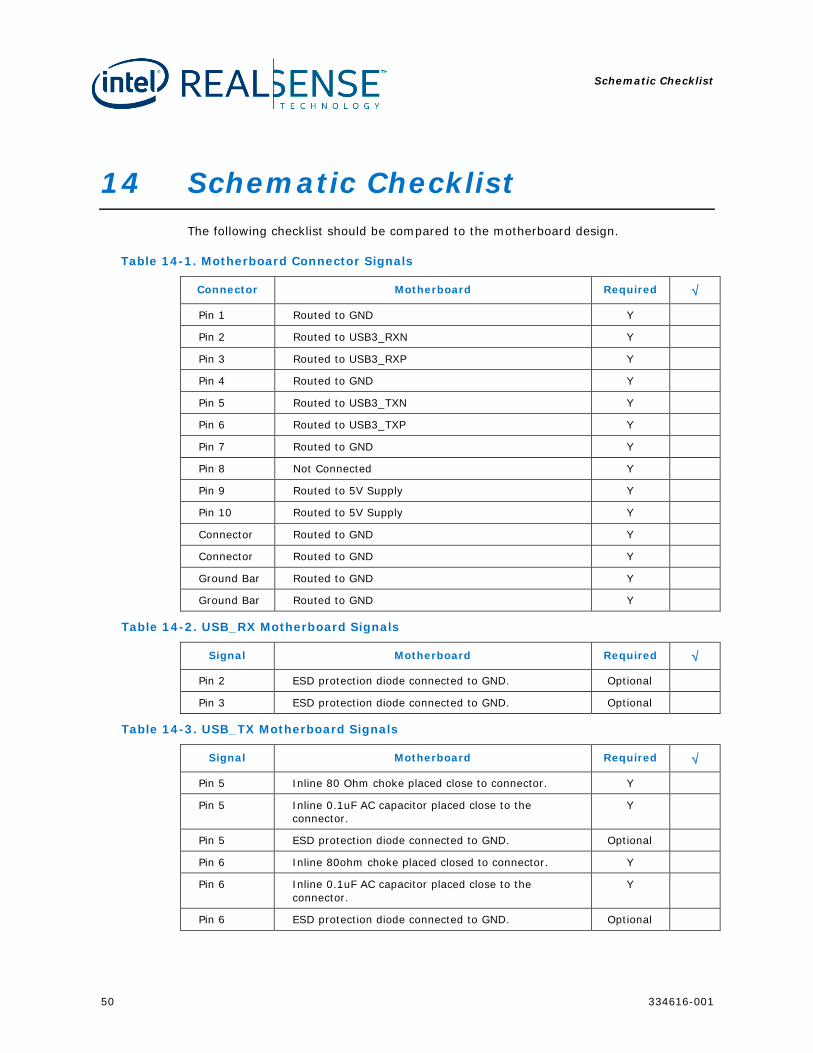
14 Schematic Checklist The following checklist should be compared to the motherboard design.
Table 14-1. Motherboard Connector Signals
Connector Motherboard Required √
Pin 1 Routed to GND Y
Pin 2 Routed to USB3_RXN Y
Pin 3 Routed to USB3_RXP Y
Pin 4 Routed to GND Y
Pin 5 Routed to USB3_TXN Y
Pin 6 Routed to USB3_TXP Y
Pin 7 Routed to GND Y
Pin 8 Not Connected Y
Pin 9 Routed to 5V Supply Y
Pin 10 Routed to 5V Supply Y
Connector Routed to GND Y
Connector Routed to GND Y
Ground Bar Routed to GND Y
Ground Bar Routed to GND Y
Table 14-2. USB_RX Motherboard Signals
Signal Motherboard Required √
Pin 2 ESD protection diode connected to GND. Optional
Pin 3 ESD protection diode connected to GND. Optional
Table 14-3. USB_TX Motherboard Signals
Signal Motherboard Required √
Pin 5 Inline 80 Ohm choke placed close to connector. Y
Pin 5 Inline 0.1uF AC capacitor placed close to the connector.
Y
Pin 5 ESD protection diode connected to GND. Optional
Pin 6 Inline 80ohm choke placed closed to connector. Y
Pin 6 Inline 0.1uF AC capacitor placed close to the connector.
Y
Pin 6 ESD protection diode connected to GND. Optional
Schematic Checklist
334616-001 51
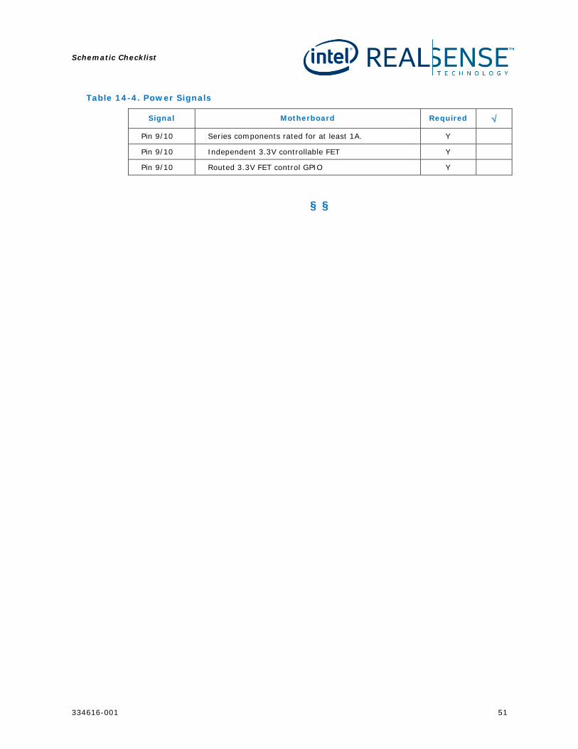
Table 14-4. Power Signals
Signal Motherboard Required √
Pin 9/10 Series components rated for at least 1A. Y
Pin 9/10 Independent 3.3V controllable FET Y
Pin 9/10 Routed 3.3V FET control GPIO Y
§ §