realstruktur von kristallen und ihre analytik fileorthorhombic body centered 7. orthorhombic face...
TRANSCRIPT

Realstruktur von Kristallen und ihre Analytik
WS 2016/17
Prof. Dr. Ullrich Pietsch
Dr. habil. Souren Grigorian [email protected]
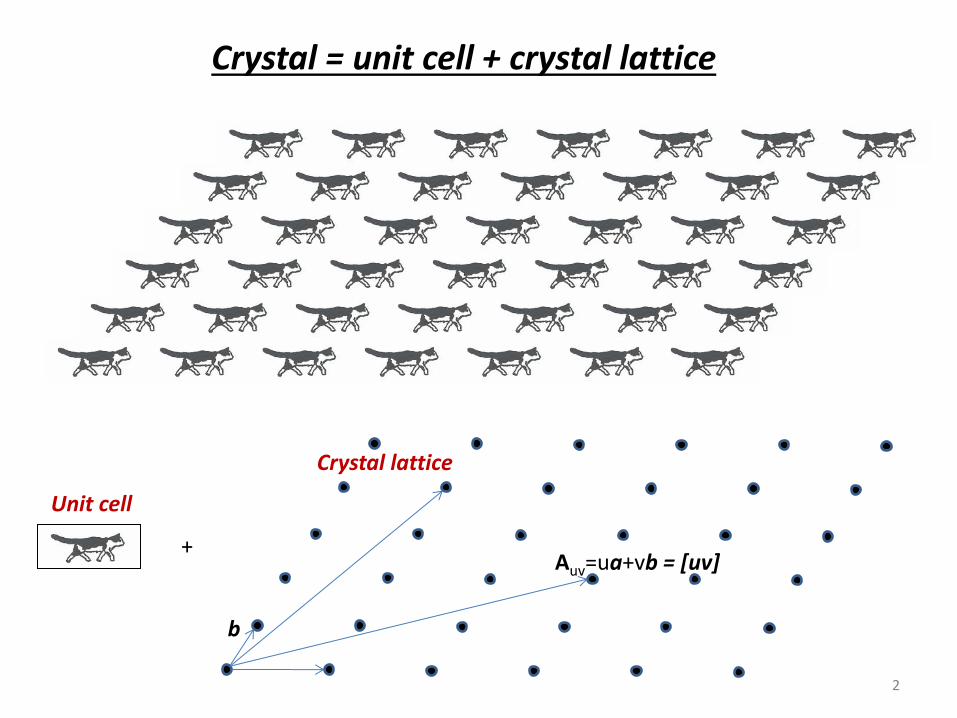
Crystal = unit cell + crystal lattice
+
Unit cell
Crystal lattice
b
Auv=ua+vb = [uv]
2

a a
a
a a
a
90-a
A2 A1
A1A2 = 2 a sin (90 – a) = 2 a cos a, Therefore
cos a = N / 2
N cos a a, deg Order of symmetry axis
-2 -1 180 2
-1 -0.5 120 3
0 0 90 4
1 0.5 60 6
2 1 0 ∞
3
m mirror Symmetry elements
Rotation axes
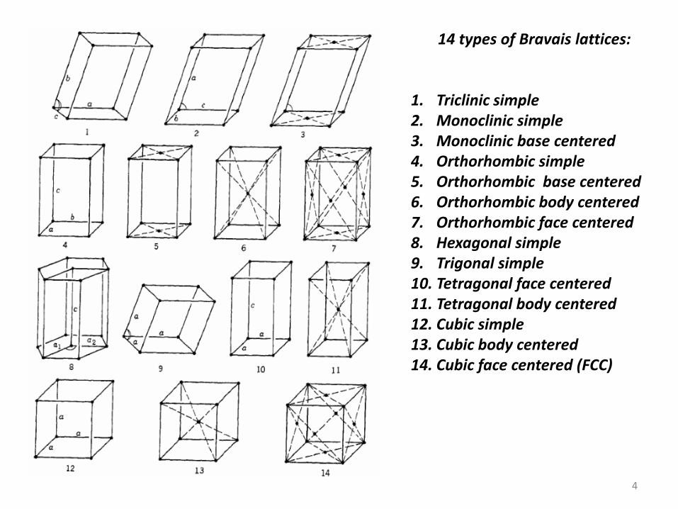
14 types of Bravais lattices:
1. Triclinic simple 2. Monoclinic simple 3. Monoclinic base centered 4. Orthorhombic simple 5. Orthorhombic base centered 6. Orthorhombic body centered 7. Orthorhombic face centered 8. Hexagonal simple 9. Trigonal simple 10. Tetragonal face centered 11. Tetragonal body centered 12. Cubic simple 13. Cubic body centered 14. Cubic face centered (FCC)
4
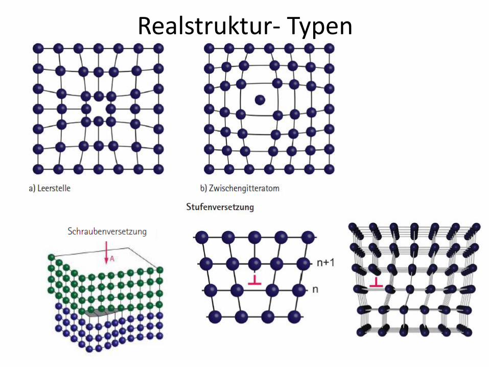
Realstruktur- Typen

Erzeugung von Röntgenstrahlen
100 Years of Crystallography Vortrag Röntgenröhren, Komponenten des Röntgenspektrums: Bremsstrahlung und Charakteristische Emissionslinien Mosley´sches Gesetz , Röntgenfluoreszenz als Methode der Analyse der Materialzusammensetzung Deutung des Laue Experiments : 1. Röntgenstrahlen sind elektromagnetische Wellen 2. Beugungsreflexe enstehen durch Interferenz der an verscheidenen Atomorten
gestreuten Welle - Atomare Abstände sind in der Größenordnung der Wellenlänge Bragg´sche Gleichung als Beugung an Netzebenen = Analogie zur Interferenz an einer planparallele Platte
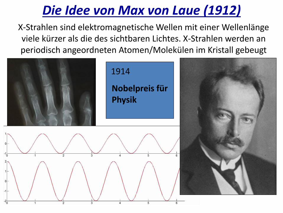
Die Idee von Max von Laue (1912) X-Strahlen sind elektromagnetische Wellen mit einer Wellenlänge viele kürzer als die des sichtbaren Lichtes. X-Strahlen werden an periodisch angeordneten Atomen/Molekülen im Kristall gebeugt
1914
Nobelpreis für Physik
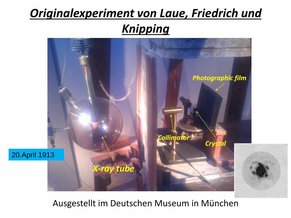
Originalexperiment von Laue, Friedrich und Knipping
X-ray tube
Photographic film
Collimator Crystal
Ausgestellt im Deutschen Museum in München
20.April 1913

Photographic film
Erster Kristall
Cu2SO4 ⋅ 5 H2O
Erstes Laue Experiment

Erklärung durch Interferenz am 3D Gitter

Beschreibung der Röntgenstrahlinter-ferenzen durch W.H.Bragg und W.L.Bragg
Interferenz an dicht mit Atomen
Besetzten „Netzebenen“
L=2dsinQ
Bragg´sche Gleichung

1912: Begin der moderen Kristallographie
X-Strahlen sind elektromagnetische Wellen mit sehr kurzer Wellenlänge ( ~ 1 Å = 10-10 m).
Kristalle sind periodische Strukturen: die innerkristallinen Abstände sind von gleicher
Größenordnung wie die Wellenlänge der Röntgenstrahlen.
Röntgenbeugung ist eine Methode zur Untersuchung der Struktur von Festkörpern !
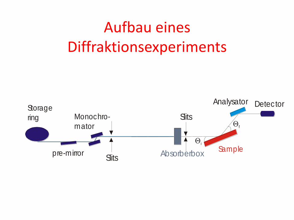
Aufbau eines Diffraktionsexperiments
Qi
Slits
Detector
AbsorberboxSample
Analysator
pre-mirror
Monochro-
mator
Slits
Qf
Storage
ring

Aufbau Röntgenröhre
E = h v = e U
lmin= h c / e U lmin[A]= 12.4/ U[keV]
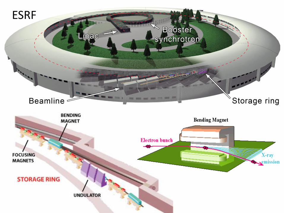
ESRF

Synchrotronstrahlung entsteht bei Beschleunigung von geladenen Teilchen in Ringbeschleunigern, wenn deren Geschwindigkeit v nahe der Lichtgeschwindigkeit c ist , d.h. wenn v ≈ c
Konsequenz der Relativitätstheorie
Nichts ist schneller als das Licht
Bewegte Uhren gehen langsamer
Entstehung von Synchrotronstrahlung
Krümmung der Elektronenbahn
durch Ablenkmagnete
Lorentzkraft F = q v x B
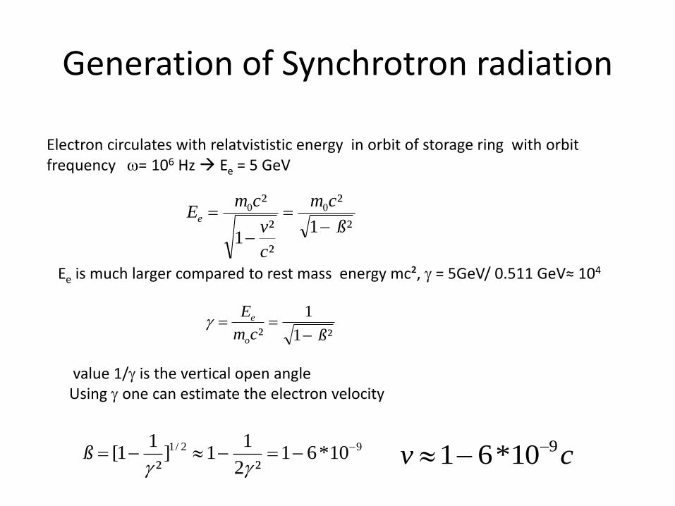
Generation of Synchrotron radiation
Electron circulates with relatvististic energy in orbit of storage ring with orbit frequency w= 106 Hz Ee = 5 GeV
²1
²
²
²1
² 00
ß
cm
c
v
cmEe
-=
-
=
Ee is much larger compared to rest mass energy mc², g = 5GeV/ 0.511 GeV≈ 104
²1
1
² ßcm
E
o
e
-==g
value 1/g is the vertical open angle Using g one can estimate the electron velocity
92/1 10*61²2
11]
²
11[ --=--=
ggß cv 910*61 --

Generation of Synchrotron radiation
Supposing the circulating electron emits a photon at point A of orbit. M Elektron proceeds to point C via B on orbit. At point C it emits a second photon. For the electron the length AC (electron) = v* dt . For the photon emitted in A reaches this distance is AC(photon = c *dt The spatial distance between both waves : (c-v) dt An observer at point C the light pulse has a length
´²)1(´)(
dtc
dtvct -=
-=

Generation of Synchrotron radiation
Considering the opening angle a = 1/g due to electron orbit
´²2
)²(1´)]
2
²1)(
²2
11(1[´)cos1( dtdtdtt
g
aga
ga
---=-=
For a =0 ´10´
²2
1 8dtdtt -=g
Dilatation of time a consequences for spectral distribution of photon emission
Orbit time of electron along AC differs from time of photon
sTphotont
sTelectront
18
10
10³2
11
²2
1)(
101
2
1)´(
-
-
==
==
wggwg
gwg

Generation of Synchrotron radiation
Inverse pulse length determines the spectral with of light emission
The emission spectrum has a critical wave length given by
This is x-ray range. In energy :
Hzc
1810³2
3= wgw
mc
c
10
18
8
1010
10 -===
l
)()(*655.0³2
3 2 TBGeVEec = wgw
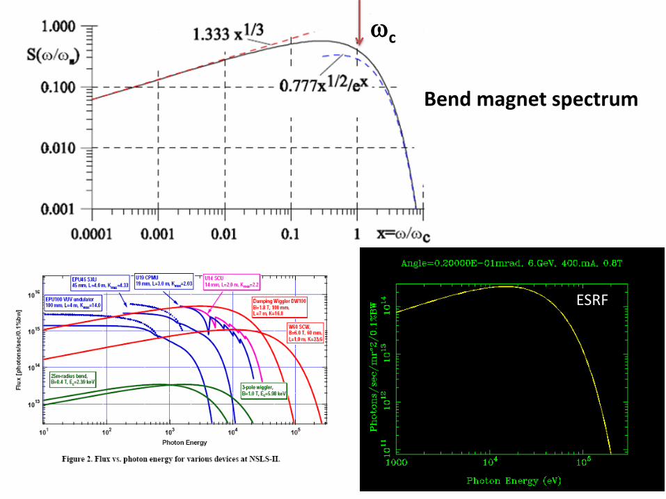
wc
Bend magnet spectrum
ESRF
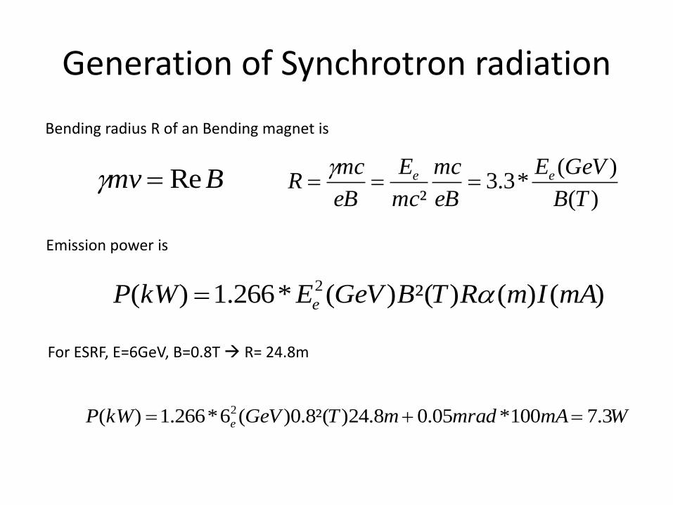
Generation of Synchrotron radiation
Bending radius R of an Bending magnet is
Emission power is
For ESRF, E=6GeV, B=0.8T R= 24.8m
Bmv Re=g)(
)(*3.3
² TB
GeVE
eB
mc
mc
E
eB
mcR ee ===
g
)()()²()(*266.1)( 2 mAImRTBGeVEkWP e a=
WmAmradmTGeVkWP e 3.7100*05.08.24)²(8.0)(6*266.1)( 2 ==