realtime hdr (high dynamic range) video for eyetap wearable...
TRANSCRIPT
REALTIME HDR (HIGH DYNAMIC RANGE) VIDEO FOR EYETAP WEARABLECOMPUTERS, FPGA-BASED SEEING AIDS, AND GLASSEYES (EYETAPS)∗
Steve Mann, Raymond Chun Hing Lo, Kalin Ovtcharov, Shixiang Gu, David Dai, Calvin Ngan, Tao Ai
University of Toronto
ABSTRACT
Realtime video HDR (High Dynamic Range) is presented inthe context of a seeing aid designed originally for task-specificuse (e.g. electric arc welding). It can also be built into regulareyeglasses to help people see better in everyday life.
Our prototype consists of an EyeTap (electric glasses) weld-ing helmet, with a wearable computer upon which are imple-mented a set of image processing algorithms that implementrealtime HDR (High Dynamic Range) image processing to-gether with applications such as mediated reality, augmediatedTM ,and augmented reality.
The HDR video system runs in realtime and processes 120frames per second, in groups of three frames or four frames(e.g. a set of four differently exposed images captured everythirtieth of a second). The processing method, for implemen-tation on FPGAs (Field Programmable Gate Arrays), achievesa realtime performance for creating HDR video using ournovel compositing methods, and runs on a miniature self-contained battery-operated head-worn circuit board, withoutthe need for a host computer. The result is an essentially self-contained miniaturizable hardware HDR camera system thatcould be built into smaller eyeglass frames, for use in vari-ous wearable computing and mediated/ aug-mediated realityapplications, as well as to help people see better in their ev-eryday lives.
Index Terms— High Dynamic Range Video, FPGAs,EyeTap, Wearable Computing, Realtime HDR, Welding, Dy-namage Range
1. INTRODUCTIONExisting cameras can only sense a limited dynamic range,much less than the human eye. One method to overcomethis limit is to combine differently exposed images of thesame subject matter, resulting in a high dynamic range (HDR)image.[1, 2, 3, 4]
The history of high dynamic range digital photographygoes back almost two decades, as Robertson et al. state[3]:
“The first report of digitally combining multiplepictures of the same scene to improve dynamicrange appears to be Mann[1]”
*GLASSEYES, GLASSEYE, EYETAP, MANNVIS, MANNGLASS, AND AUGMEDIATED REALTY ARETRADEMARKS OF AUTHOR S. MANN
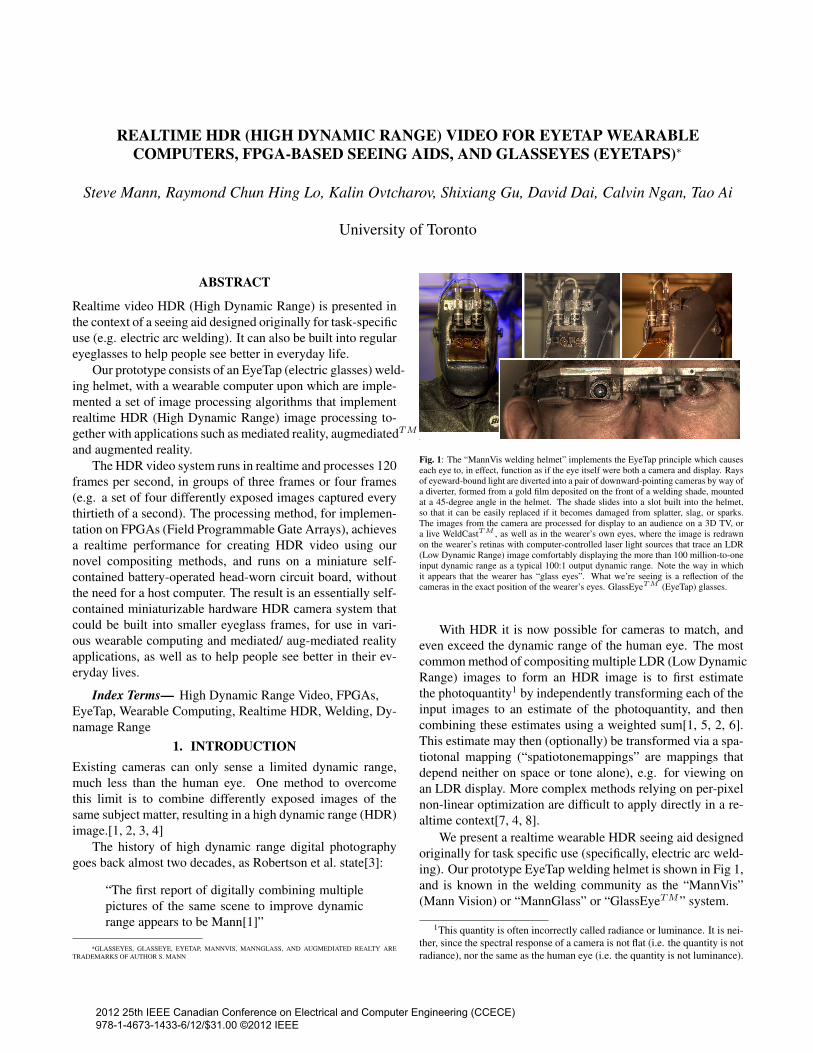
Fig. 1: The “MannVis welding helmet” implements the EyeTap principle which causeseach eye to, in effect, function as if the eye itself were both a camera and display. Raysof eyeward-bound light are diverted into a pair of downward-pointing cameras by way ofa diverter, formed from a gold film deposited on the front of a welding shade, mountedat a 45-degree angle in the helmet. The shade slides into a slot built into the helmet,so that it can be easily replaced if it becomes damaged from splatter, slag, or sparks.The images from the camera are processed for display to an audience on a 3D TV, ora live WeldCastTM , as well as in the wearer’s own eyes, where the image is redrawnon the wearer’s retinas with computer-controlled laser light sources that trace an LDR(Low Dynamic Range) image comfortably displaying the more than 100 million-to-oneinput dynamic range as a typical 100:1 output dynamic range. Note the way in whichit appears that the wearer has “glass eyes”. What we’re seeing is a reflection of thecameras in the exact position of the wearer’s eyes. GlassEyeTM (EyeTap) glasses.
With HDR it is now possible for cameras to match, andeven exceed the dynamic range of the human eye. The mostcommon method of compositing multiple LDR (Low DynamicRange) images to form an HDR image is to first estimatethe photoquantity1 by independently transforming each of theinput images to an estimate of the photoquantity, and thencombining these estimates using a weighted sum[1, 5, 2, 6].This estimate may then (optionally) be transformed via a spa-tiotonal mapping (“spatiotonemappings” are mappings thatdepend neither on space or tone alone), e.g. for viewing onan LDR display. More complex methods relying on per-pixelnon-linear optimization are difficult to apply directly in a re-altime context[7, 4, 8].
We present a realtime wearable HDR seeing aid designedoriginally for task specific use (specifically, electric arc weld-ing). Our prototype EyeTap welding helmet is shown in Fig 1,and is known in the welding community as the “MannVis”(Mann Vision) or “MannGlass” or “GlassEyeTM” system.
1This quantity is often incorrectly called radiance or luminance. It is nei-ther, since the spectral response of a camera is not flat (i.e. the quantity is notradiance), nor the same as the human eye (i.e. the quantity is not luminance).
2012 25th IEEE Canadian Conference on Electrical and Computer Engineering (CCECE) 978-1-4673-1433-6/12/$31.00 ©2012 IEEE
Our realtime video HDR work, however, has many morefar-reaching applications, including:
• as a general-purpose seeing aid, it consists of an Eye-Tap camera system connected to a wearable computerutilizing a set of image processing algorithms that im-prove the wearer’s vision through HDR, along with me-diated and aug-mediated reality;
• as a drop-in replacement for security cameras, e.g. forgeneral purpose surveillance and sousveillance (e.g. in-verse surveillance);
• for general purpose video cameras both hand-held andtripod-mounted, etc.
Our hardware implementation uses Field ProgrammableGate Arrays (FPGAs). Our initial prototype includes a low-power (battery-powered) circuit board, which is presently smallenough to fit inside a large shirt pocket or inside the MannViswelding helmet.
Our design is miniaturizable, in the sense that a new cir-cuit board layout can be made to fit into the temple side-piecesof eyeglass frames, for example. The circuit board includestwo HDMI camera inputs, one being used for the left eye, andthe other for the right eye, as well as HDMI outputs fed backto the left and right eyes (head-up displays, EyeTaps, or thelike), after processing of the video signals. The current im-plementation runs on a Xilinx Spartan 6, model LX45 FPGA,but can be easily adapted to any of a wide variety of otherFPGAs.
2. BACKGROUND2.1. Dynamic rangeLet us begin by defining 2 kinds of dynamic range:• Transmitient dynamic range is the dynamic range in
signal production. For example, the dynamic range ofa clarinet is the range from quietest sound to loudestsound it can make;
• Recipient dynamic range is a sensed or measured dy-namic range, for example, a sensor’s dynamic range.
To the extent that what’s between these two is representableas a function, one might call the former the dynamic domainof this function, and the latter its dynamic range.
One’s first encounter with dynamic range is more likelyto be the latter than the former, i.e. concern for dynamicrange (especially its specific quantification in decibels or f-stops, or the like) is more likely to arise from devices likesound recorders and photographic cameras than from soundand light sources.
In that sense we care more about the dynamic range ofthe human eye or a camera, for example, than we do aboutthe dynamic range that COULD exist philosophically in thetransmitient sense e.g. between bright sunlight and the insideof a coffin in an Egyptian tomb deep underground.
Very few people would ask “how many dB dynamic rangeis a clarinet?”. To answer such an ill-posed question, do wetake the ratio of the loudest note to the silence it produceswhen sitting on a desk not being played? Or do we go fromthe quietest sound it can make, to the loudest sound it canmake, regarless of musical integrity? Or do we take the ratioof undistorted quietest note to undistorted loudest note. Thedynamic range would depend on how much distorition we canaccept, so it becomes very imprecise in terms of definition.
Let us therefore define dynamic range as follows:
Dynamic range is the ratio between the largestand smallest non-negative quantity such as mag-nitude, amplitude, energy, or the like, of sound,light, or the like, for which a small incrementaldifference in the quantity can still be sensed (i.e.the range over which changes in the quantity re-main discernible).
Compare with the definition provided in [9].
2.2. “Dynamage range”Let us define an additional concept called “dynamage range”as follows:
“Dynamage range” is the ratio between the largestquantity that will not damage a sensor or deviceor receiver, and the smallest non-negative quan-tity for which changes in the quantity remain dis-cernible.
HDR video was made possible by the invention of cam-eras that can be overexposed without permanent damage. Un-like old vidicon cameras for which the dynamic range anddynamage range are roughly equal, modern cameras have amuch greater dynamage range than their dynamic range.
HDR allows us to increase the dynamic range up to beingequal to the dynamage range.2.3. The EyeTap PrincipleOur experimental seeing aid system uses the MannVis weld-ing helmet (see Fig. 1), which is constructed with the formfactor of a standard welding helmet shell, but with two computer-controlled video cameras mounted in a binocular configura-tion facing downwards, pointing toward a welding shade mountedat a 45◦ pitch from the coronal plane. A gold plating on thewelding shade directs the light from the front of the wearertoward the cameras.
Additionally, a computer-controlled laser light system isbuilt into the helmet, which directs light into the wearer’seyes. In this way the system provides Mediated Reality [6], aproper superset of Augmented Reality. Augmented reality islimited in the sense that it simply adds new matter, but in thiscase what we really wish is a diminished reality, i.e. to reducethe severity of the contrast ratio.
The point-of-view of the cameras is the point-of-eye (PoE),such that each camera operates as if it were the wearer’s own
eye. The laser light image forms inside the wearer’s own reti-nas, so as to show what is present, but with dynamic rangecompression when needed. We call this “dynamic range man-agement”. With dynamic-range-management, any lightingsituation presented to the wearer is managed by the computersystem to keep the overall lighting in certain ranges. This isbeyond auto-darkening eyewear that only manages light lev-els, because now the contrast, in addition to the light levelsoverall, is managed.
2.4. Comparametric EquationsComparametric equations[2] and superposimetric equations[10]are mathematical frameworks for understanding pictures orvideo of differently exposed or differently illuminated pic-tures of otherwise identical subject matter. This conceptualframework captures the general essence of linearity and su-perposition of light, and in particular, photoquantities, irre-spective of any non-linearities that might be present in a par-ticular camera system.
In this paper we consider the situation where sequentialframes of video, fi ∈ {f1, f2, f3, . . .}, are captured in rapidsuccession, with varying exposure levels ki. These exposurelevels are controlled by the wearable computer system, forexample, to extend dynamic range, resulting in the set of dif-ferently exposed video frames, fi = f(kiq(x, y)). This set ofpictures is used to estimate the true photoquantity, q(x, y) (aspatially varying quantimetric measure of light on the imageplane defined by coordinates x and y).
3. REALTIME HDR
In this section we discuss a novel HDR image compositionmethod, optimized for FPGA hardware implementation ofelectric eyeglasses. This method, advancing upon the resultsin [1, 3, 11], is adapted specifically for direct hardware imple-mentation, as opposed to assuming the availability of a multi-core CPU or GPU. Additionally, we present how this methodcan be extended to three or more images in extreme dynamicrange cases using simple binary operators.
3.1. Mathematical NotationWe let f as a function represent the camera response function(CRF), while f in a scalar context is a tonal value, and in amatrix context f is a tonal image (e.g. a picture from a cam-era). We consider a tonal value f to vary linearly with pixelvalue but on the unit interval, and given an n-bit pixel value vreturned from a physical camera, we use fi = (v + 0.5)/2n,where we have N images, i ∈ {1, . . . , N}, and each imagehas exposure ki. The subscript indicates it is the i-th in aWyckoff set[2], i.e. a set of images differing only in exposure,and by convention ki < ki+1 ∀ i < N . We use f−1 as themathematical inverse of f if it has only one argument, andotherwise as a joint estimator2 of photoquantity, q.
2“Joint estimator” is used here in the sense that each photoquantity esti-mate depends simultaneously on multiple measurements.
3.2. Direct Lookup method for combining exposuresFor the case of compositing two images with 8-bit color depthper channel, a simple size 256×256×3 LUT can be derivedfor each camera. The LUT need only be computed once eachtime a new camera is plugged in for the first time.
3.2.1. Constructing the inverse comparametric LUTThe inverse comparametric lookup table (CLUT) is a compo-sition of a set of operations for creating HDR images froman alternating exposure set. To construct this look-up-table,we first estimate the response function of the camera alongwith its certainty function using the method described in Sec-tion 2.4.
An estimate, q, of the photoquantity is computed fromthe pixel (tonal) values f1 and f2. This can be by weightedaverage with the certainty function w and with the responsefunction f of the camera. To speedup the process (for real-time video) this may be done using conditional statements inhandling the saturated regions:
q =f−1∆EV (f1, f2)
=
qmax if f1 > β,
qmin if f2 < α ,f−1(f1)·w(f1)+f−1(f2)·w(f2) /2∆EV
w(f1)+w(f2) otherwise,
(1)
where β and α are the saturation parameters of the camera(Typical values are β = 250 and α = 5.) and ∆EV is theexposure difference between f1 and f2, and qmax and qminare the estimated q values at the saturation points, f−1(β)and f−1(α) respectively.
In our prototype, we configured the camera to capture im-ages that are 4 stops part (i.e., one image has an exposure timethat is 24 = 16 times longer or shorter than the other).
Once we have estimated q from the image set, we performdynamic range compression (tone mapping) for LDR display.Empirically, we have found that the following function canprovide adequate dynamic range compression and works wellfor general high dynamic range scenes.
qc = c(q) = r · q1/k + d (2)
where r, k, and d can be used to adjust “contrast” and “bright-ness” of the output image (e.g., k=5, d=-1.0, and r=1.8).
After we have obtained a new range-compressed qc, wecan estimate the output value by applying the CRF to the qc.Since the equation of the CRF may not have a closed formsolution, we can simply perform a nearest neightbour searchwhich minimizes the absolute distance between the qc and theq from the response function of the camera.
Q =argminz∈N
(|f−1(z)− qc|) (3)
Notice that now Q is a quantized output which maps to therange [0-255] for LDR displays. To further adjust the con-trast level of the image, we can aggregate an additional tonal
k(f(c(f−1∆EV (f1, f2))))
f1
f2
f1
f2
Input Images Output Image
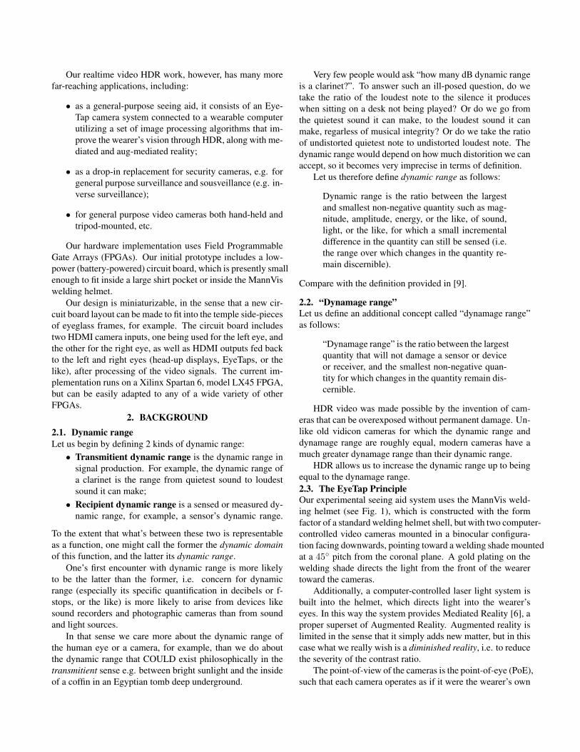
Fig. 2: The composite direct lookup method. The lookup table Qf (center) is thevalue of the composition of functions k ◦ f ◦ c ◦ f−1
∆EV , where f−1∆EV is the joint
photoquantity estimator function for two exposures ∆EV apart, c is the dynamic rangecompression function, f is the CRF, and k is the contrast enhancement function. Thevalue of Qf (f1, f2) is evaluated at all possible values of f1 and f2, to create thelookup table shown here. This method can be extended to 12-bit or 14-bit images by ap-plying linear interpolation to obtain intermediate values from an arbitrarily-sized table.
adjustment function k to the final result.
Qf = k(Q) (4)
where k can be a simple look up table for the desired colorprofile.
Lastly, we combined the above functions and obtained asolution for all possible values of f1 and f2. The result is asshown in Figure 2.
Qf = k(f(c(f−1∆EV (f1, f2)))) = CLUT(f1, f2) (5)
3.3. Compositing 3 or more exposuresFor the case of constructing HDR images from 3 or more im-ages, we can compute an intermediate estimation of the pho-tographic quantities qi using Eq. 1. Since the images onlydiffer in exposures (i.e., 4 stops in our case), the same LUTwhich precomputed the qi can be applied to the image pairsat no additional computational cost.
qi = f−1∆EV (fi, fi+1), i ∈ {1, .., N} (6)
wi = max(w(fi), w(fi+1)), i ∈ {1, .., N} (7)
Then, we combine the individual photoquantity qi with thecertainty values wi computed from last step with:
q = g(qi, qi+1, ..., qN−1, wi, wi+1, ..., wN−1) (8)
to create our final estimate of q. For the case of 3 images, thefunction g can be implemented as a simple weighted averageof the q1 and q2 with respect to the certainty values w1 andw2:
q = g(q1, q2, w1, w2) =q1 · w1 + q2 · w2/2
∆EV
w1 + w2
(9)
One advantage of our algorithm is that we have reduced theproblem into sub-steps that we can easily optimize for specificalgorithm, and can provide a significant speedup.
f1 f2 f3
q2q1
q
tonemapping
∆EV = 4∆EV = 4
∆EV = 4
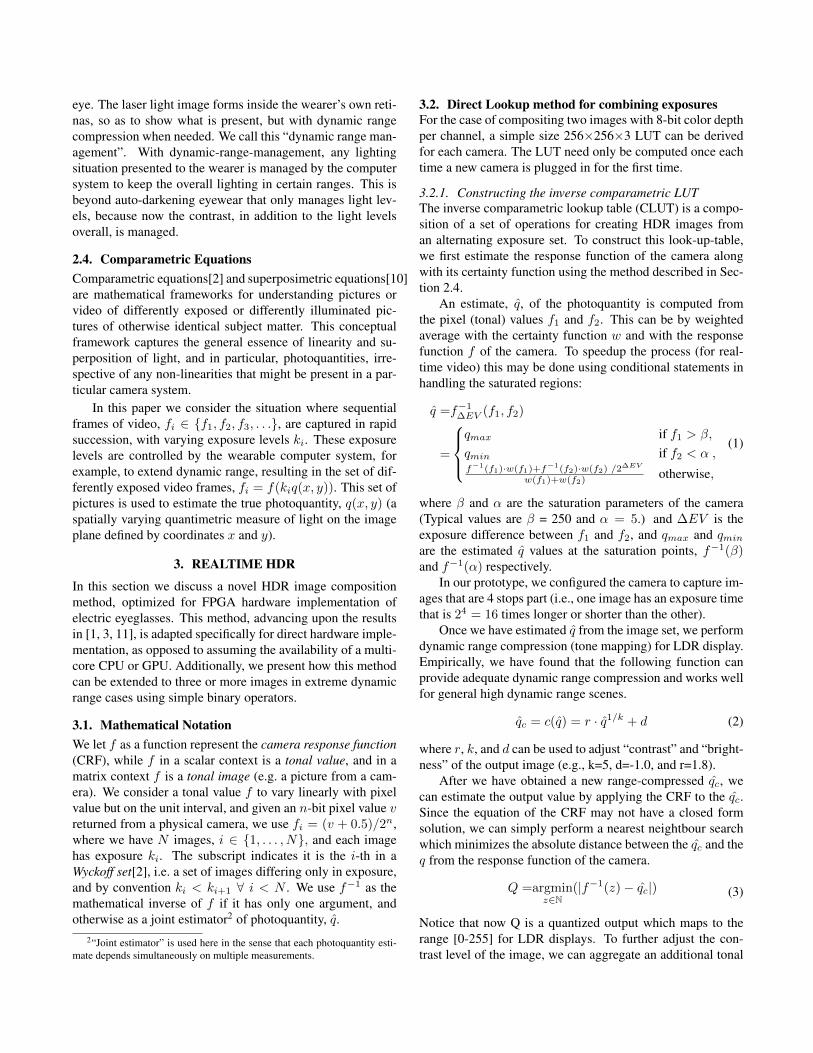
Fig. 3: Composition of HDR images using our pairwise approach for combining threeLDR images, f1, f2, f3. The final estimate of the photoquantity q then undergoes ourtonemapping.
With an image set of 3 differently exposed images, wehave further extended the dynamic range by another 4 stops,a total of 8 stops of additional range. The compressor functionin Eq. 2, however, is no longer suitable for such wide dynamicrange. Particularly, we found the contrast of the image waspoor and there was a lack of saturation. A piecewise functionwhich places emphasis on to the highlights is used. Despitethe simplicity of our piecewise dynamic range compressor,it provides natural looking results without accentuating noiseand other artifacts:
qc = c(q) =
{r · (s · q)1/k + d if q ≤ 1/s,
r · (s · q)1/(γ·k) + d if q > 1/s.(10)
In our setup, we have used values r = 1.8, k = 4, d = −1.2,γ = 1.5, s = 140, and q is normalized to [0,1].
At last, the range-compressed image qc was mapped to theLDR display using Eq. 3 and 4. To enhance the local contrastof the final image, we applied an unsharp mask to the finalimage. The final and intermediate results of our algorithm areshown in Figure 3.
3.4. Exposure pruning for further speedup
The composition technique introduced in Section 3.3 can besimplified further by computing multiple LUTs in extremedynamic range scenarios. Under these extreme conditions,e.g. compositing three images that are 4 stops apart (i.e.,∆EV = 4), the exposure difference between the f1 and f3 isa full 8 stops, (∆EV = 8). Since there is very little overlapbetween lightest and darkest image, we can obtain a furtherspeedup by pruning image pairs and discarding the exposuresthat provide very little or no additional scene information. Inthe case of 3 exposures that are 4 stops apart, we have used thefollowing conditional statement to select the candidate image
f2
f1
f2
Input Images
Output Image
k(f(c(2∆EV · f−1∆EV (f2, f3))))
f2
f1
f3
k(f(c(f−1∆EV (f1, f2))))
f3
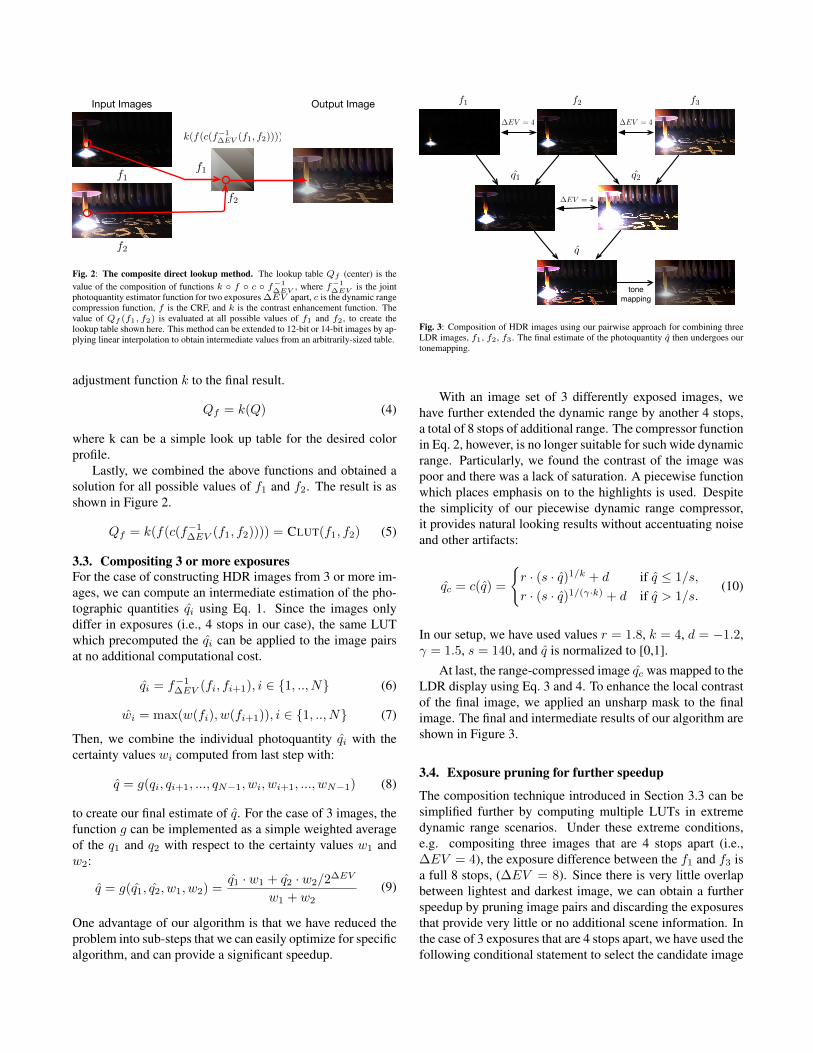
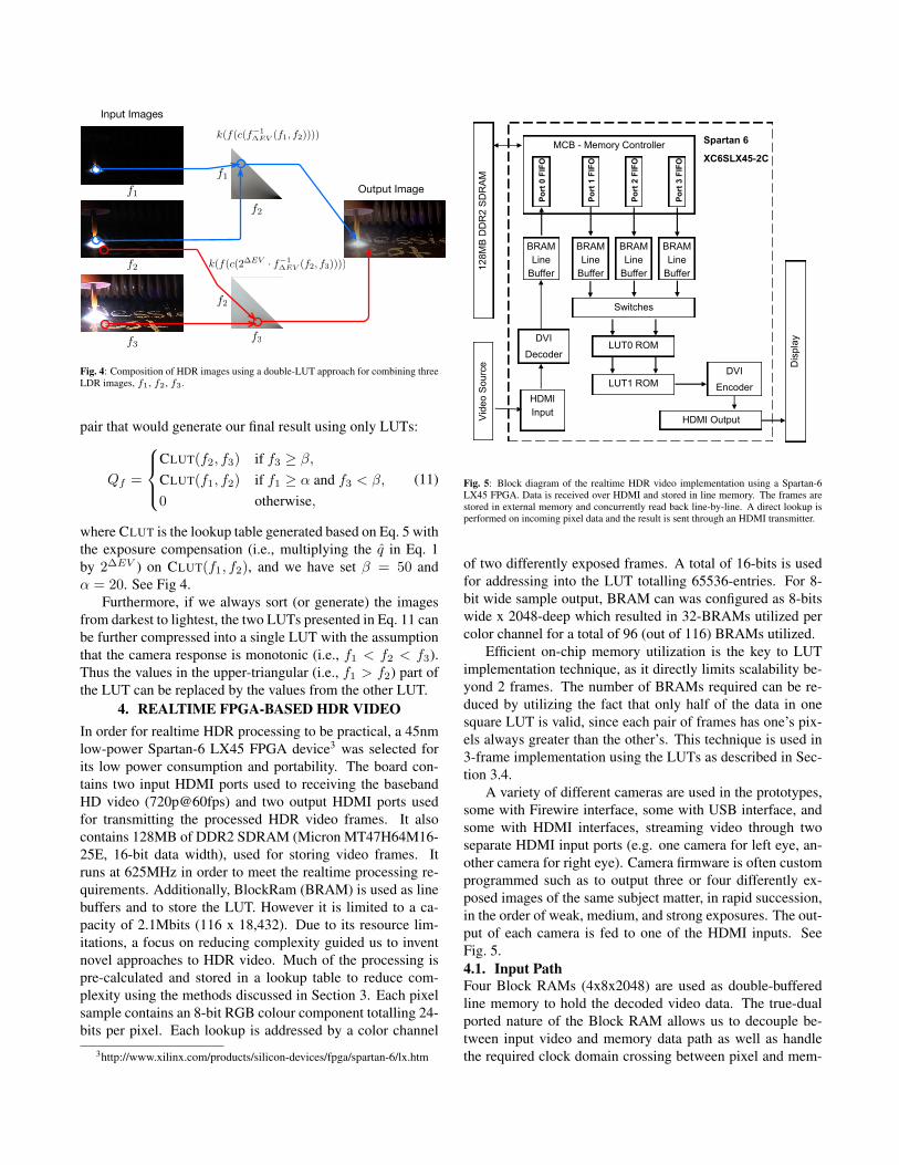
Fig. 4: Composition of HDR images using a double-LUT approach for combining threeLDR images, f1, f2, f3.
pair that would generate our final result using only LUTs:
Qf =
CLUT(f2, f3) if f3 ≥ β,CLUT(f1, f2) if f1 ≥ α and f3 < β,
0 otherwise,(11)
where CLUT is the lookup table generated based on Eq. 5 withthe exposure compensation (i.e., multiplying the q in Eq. 1by 2∆EV ) on CLUT(f1, f2), and we have set β = 50 andα = 20. See Fig 4.
Furthermore, if we always sort (or generate) the imagesfrom darkest to lightest, the two LUTs presented in Eq. 11 canbe further compressed into a single LUT with the assumptionthat the camera response is monotonic (i.e., f1 < f2 < f3).Thus the values in the upper-triangular (i.e., f1 > f2) part ofthe LUT can be replaced by the values from the other LUT.
4. REALTIME FPGA-BASED HDR VIDEOIn order for realtime HDR processing to be practical, a 45nmlow-power Spartan-6 LX45 FPGA device3 was selected forits low power consumption and portability. The board con-tains two input HDMI ports used to receiving the basebandHD video (720p@60fps) and two output HDMI ports usedfor transmitting the processed HDR video frames. It alsocontains 128MB of DDR2 SDRAM (Micron MT47H64M16-25E, 16-bit data width), used for storing video frames. Itruns at 625MHz in order to meet the realtime processing re-quirements. Additionally, BlockRam (BRAM) is used as linebuffers and to store the LUT. However it is limited to a ca-pacity of 2.1Mbits (116 x 18,432). Due to its resource lim-itations, a focus on reducing complexity guided us to inventnovel approaches to HDR video. Much of the processing ispre-calculated and stored in a lookup table to reduce com-plexity using the methods discussed in Section 3. Each pixelsample contains an 8-bit RGB colour component totalling 24-bits per pixel. Each lookup is addressed by a color channel
3http://www.xilinx.com/products/silicon-devices/fpga/spartan-6/lx.htm
12
8M
B D
DR
2 S
DR
AM
MCB - Memory Controller
BRAM
Line
Buffer
BRAM
Line
Buffer
BRAM
Line
Buffer
BRAM
Line
Buffer
DVI
Decoder
Switches
LUT0 ROM
LUT1 ROM
DVI
Encoder HDMI
Input HDMI Output V
ide
o S
ou
rce
Dis
pla
y
Spartan 6
XC6SLX45-2C
Po
rt 0
FIF
O
Po
rt 1
FIF
O
Po
rt 2
FIF
O
Po
rt 3
FIF
O
Fig. 5: Block diagram of the realtime HDR video implementation using a Spartan-6LX45 FPGA. Data is received over HDMI and stored in line memory. The frames arestored in external memory and concurrently read back line-by-line. A direct lookup isperformed on incoming pixel data and the result is sent through an HDMI transmitter.
of two differently exposed frames. A total of 16-bits is usedfor addressing into the LUT totalling 65536-entries. For 8-bit wide sample output, BRAM can was configured as 8-bitswide x 2048-deep which resulted in 32-BRAMs utilized percolor channel for a total of 96 (out of 116) BRAMs utilized.
Efficient on-chip memory utilization is the key to LUTimplementation technique, as it directly limits scalability be-yond 2 frames. The number of BRAMs required can be re-duced by utilizing the fact that only half of the data in onesquare LUT is valid, since each pair of frames has one’s pix-els always greater than the other’s. This technique is used in3-frame implementation using the LUTs as described in Sec-tion 3.4.
A variety of different cameras are used in the prototypes,some with Firewire interface, some with USB interface, andsome with HDMI interfaces, streaming video through twoseparate HDMI input ports (e.g. one camera for left eye, an-other camera for right eye). Camera firmware is often customprogrammed such as to output three or four differently ex-posed images of the same subject matter, in rapid succession,in the order of weak, medium, and strong exposures. The out-put of each camera is fed to one of the HDMI inputs. SeeFig. 5.4.1. Input PathFour Block RAMs (4x8x2048) are used as double-bufferedline memory to hold the decoded video data. The true-dualported nature of the Block RAM allows us to decouple be-tween input video and memory data path as well as handlethe required clock domain crossing between pixel and mem-
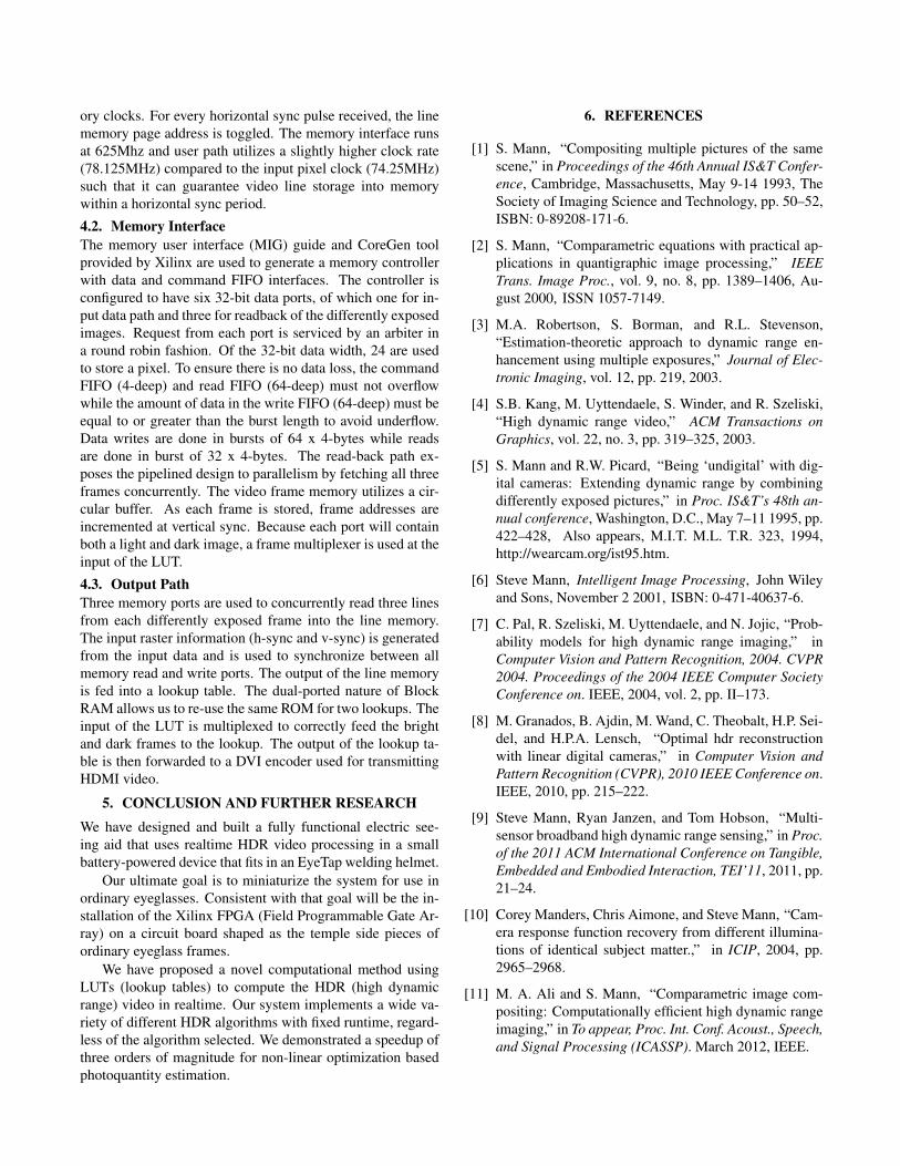
ory clocks. For every horizontal sync pulse received, the linememory page address is toggled. The memory interface runsat 625Mhz and user path utilizes a slightly higher clock rate(78.125MHz) compared to the input pixel clock (74.25MHz)such that it can guarantee video line storage into memorywithin a horizontal sync period.
4.2. Memory InterfaceThe memory user interface (MIG) guide and CoreGen toolprovided by Xilinx are used to generate a memory controllerwith data and command FIFO interfaces. The controller isconfigured to have six 32-bit data ports, of which one for in-put data path and three for readback of the differently exposedimages. Request from each port is serviced by an arbiter ina round robin fashion. Of the 32-bit data width, 24 are usedto store a pixel. To ensure there is no data loss, the commandFIFO (4-deep) and read FIFO (64-deep) must not overflowwhile the amount of data in the write FIFO (64-deep) must beequal to or greater than the burst length to avoid underflow.Data writes are done in bursts of 64 x 4-bytes while readsare done in burst of 32 x 4-bytes. The read-back path ex-poses the pipelined design to parallelism by fetching all threeframes concurrently. The video frame memory utilizes a cir-cular buffer. As each frame is stored, frame addresses areincremented at vertical sync. Because each port will containboth a light and dark image, a frame multiplexer is used at theinput of the LUT.
4.3. Output PathThree memory ports are used to concurrently read three linesfrom each differently exposed frame into the line memory.The input raster information (h-sync and v-sync) is generatedfrom the input data and is used to synchronize between allmemory read and write ports. The output of the line memoryis fed into a lookup table. The dual-ported nature of BlockRAM allows us to re-use the same ROM for two lookups. Theinput of the LUT is multiplexed to correctly feed the brightand dark frames to the lookup. The output of the lookup ta-ble is then forwarded to a DVI encoder used for transmittingHDMI video.
5. CONCLUSION AND FURTHER RESEARCHWe have designed and built a fully functional electric see-ing aid that uses realtime HDR video processing in a smallbattery-powered device that fits in an EyeTap welding helmet.
Our ultimate goal is to miniaturize the system for use inordinary eyeglasses. Consistent with that goal will be the in-stallation of the Xilinx FPGA (Field Programmable Gate Ar-ray) on a circuit board shaped as the temple side pieces ofordinary eyeglass frames.
We have proposed a novel computational method usingLUTs (lookup tables) to compute the HDR (high dynamicrange) video in realtime. Our system implements a wide va-riety of different HDR algorithms with fixed runtime, regard-less of the algorithm selected. We demonstrated a speedup ofthree orders of magnitude for non-linear optimization basedphotoquantity estimation.
6. REFERENCES
[1] S. Mann, “Compositing multiple pictures of the samescene,” in Proceedings of the 46th Annual IS&T Confer-ence, Cambridge, Massachusetts, May 9-14 1993, TheSociety of Imaging Science and Technology, pp. 50–52,ISBN: 0-89208-171-6.
[2] S. Mann, “Comparametric equations with practical ap-plications in quantigraphic image processing,” IEEETrans. Image Proc., vol. 9, no. 8, pp. 1389–1406, Au-gust 2000, ISSN 1057-7149.
[3] M.A. Robertson, S. Borman, and R.L. Stevenson,“Estimation-theoretic approach to dynamic range en-hancement using multiple exposures,” Journal of Elec-tronic Imaging, vol. 12, pp. 219, 2003.
[4] S.B. Kang, M. Uyttendaele, S. Winder, and R. Szeliski,“High dynamic range video,” ACM Transactions onGraphics, vol. 22, no. 3, pp. 319–325, 2003.
[5] S. Mann and R.W. Picard, “Being ‘undigital’ with dig-ital cameras: Extending dynamic range by combiningdifferently exposed pictures,” in Proc. IS&T’s 48th an-nual conference, Washington, D.C., May 7–11 1995, pp.422–428, Also appears, M.I.T. M.L. T.R. 323, 1994,http://wearcam.org/ist95.htm.
[6] Steve Mann, Intelligent Image Processing, John Wileyand Sons, November 2 2001, ISBN: 0-471-40637-6.
[7] C. Pal, R. Szeliski, M. Uyttendaele, and N. Jojic, “Prob-ability models for high dynamic range imaging,” inComputer Vision and Pattern Recognition, 2004. CVPR2004. Proceedings of the 2004 IEEE Computer SocietyConference on. IEEE, 2004, vol. 2, pp. II–173.
[8] M. Granados, B. Ajdin, M. Wand, C. Theobalt, H.P. Sei-del, and H.P.A. Lensch, “Optimal hdr reconstructionwith linear digital cameras,” in Computer Vision andPattern Recognition (CVPR), 2010 IEEE Conference on.IEEE, 2010, pp. 215–222.
[9] Steve Mann, Ryan Janzen, and Tom Hobson, “Multi-sensor broadband high dynamic range sensing,” in Proc.of the 2011 ACM International Conference on Tangible,Embedded and Embodied Interaction, TEI’11, 2011, pp.21–24.
[10] Corey Manders, Chris Aimone, and Steve Mann, “Cam-era response function recovery from different illumina-tions of identical subject matter.,” in ICIP, 2004, pp.2965–2968.
[11] M. A. Ali and S. Mann, “Comparametric image com-positing: Computationally efficient high dynamic rangeimaging,” in To appear, Proc. Int. Conf. Acoust., Speech,and Signal Processing (ICASSP). March 2012, IEEE.