reasoned document prepared after receipt of...
TRANSCRIPT

REASONED DOCUMENT PREPARED AFTER RECEIPT OF STAKEHOLDER’S COMMENT ON DRAFT SPECIFICATION /STR FOR LIGHT WEIGHT LOW HEIGHT 25T AXLE LOAD CAST STEEL BOGIE (LWLH25)
WITH AAR K- CLASS CTRB FOR BROAD GAUGE WAGONS DRAFT SPECIFICATION / STR No. : WD-40-LWLH25 BOGIE(“K”-Class)-2015 DATE OF UPLOADING ON WEB SITE: 21/09/2017 LAST DATE OF SUBMISSION OF COMMENTS : 21/10/2017
RDSO STR Clause no.
Draft specification /STR
0.0 PREAMBLE Presently, the main fleet of Indian Railway’s freight stocks have been provided with various variants of CASNUB bogies and are mainly operational at 22.9 T axle load. A very small number of wagons fitted with CASNUB type bogies are operational at 25 T axle load at lower speed on limited routes. Another bogie i.e LCCF(20) is operational at 20.32 T / 22.0T axle load fitted on container flat wagons. 0.0 For weight optimization of existing IR bogies, a project was taken up by RDSO with IIT, Roorkee to explore the possibility of weight reduction of existing bogie. After detailed structural, fatigue
and transient simulation studies, IIT, Roorkee submitted the final report with proposal of overall weight reduction by 145 kg by reducing the thickness of wall and some modification in design and concluded the same is safe for operation.
0.1 RDSO has entered in to a contract with ARI, USA for design development of higher axle load (25T and 32.5T) wagons. During the first phase of project design of 25 T axles load, open wagon design was conceptualized. A new indigenous version of bogie (similar to LCCF-20F) for 25 T axle load open wagon under this project was evolved for this open wagon, on the basis of confidence gained in project study done with IIT, Roorkee.
0.2 Based on the detailed simulation studies, a new optimized bogie design suitable for AAR Class “E” CTRB and designated name as Light weight Low Height (LWLH 25T) with 840 mm dia. wheel sets was finalized and circulated to all bogie manufacturers with proposed alternatives of materials and methoding to offer their comments. Comments received from the all bogie manufacturers were evaluated and for the issues regarding material selection, a meeting has been held in June 2013 with all prospective bogie manufacturers and subsequently the design has been finalized. The suspension of bogie for 25T operation has been evolved through NUCAR simulation.
0.3 Further, a variant of LWLH25 T bogie suitable for AAR Class K Class CTRB for IR wagons was proposed to be evolved by modification in side frame to suit AAR K class CTRB. Accordingly, the design of LWLH25 T bogie suitable for AAR K Class CTRB was finalized and the same has been circulated to all stakeholders for development.
0.4 During the course of above development reliability of existing bogie designs being manufactured, present methoding of casting vis-à-vis foundry practice over international rail roads has been studied and it is found no-bake or high pressure moulding method are best suited for such components for consistent quality , consistent achievable design weight and improved strength expected reliability at higher axle load. Similar opinion has also been shared by Indian bogie manufacturers when initial design of bogie was circulated to the concerned stakeholders.
0.5 RDSO has also issued a specification no WD-70-BD-10 (Rev-1) in December 2012 for upgraded high tensile CBC for fitment in BOXNHL and BCNHL wagons with mandate of no-bake or high pressure moulding method. This specification led to development of indigenous manufacturing capability and ensured couplers manufactured against this specification match up to international standards. Couplers to this specification have been performing satisfactorily in the field and addressed the quality issues of CBC manufactured earlier through green sand moulding methods.
0.6 This specification has been prepared for new optimized light weight low height bogie (lighter than existing container bogie) for use at 25 T axle loads and is expected to match up to international standards. The manufacturing process of this bogie shall also harness the capability of indigenous manufacturing facilities to switch over to improved manufacturing methods to achieve quality and reliability matching global bench marks.
0.7 Design evaluation & validation this bogie design shall be done through fatigue testing of bogie side frame and bolster in accordance with AAR test regime at RDSO fatigue laboratory to establish the design efficacy of bogie design. Further assessment, type testing of individual prospective bogie manufacturers shall be done as per detailed test plan as mentioned in this specification in the firm premises as normally been done in case of existing bogies.
Comments received from stakeholders
S. No. Name of Firm Comments
1 M/s Jupiter Alloys & Steel Limited NIL
2 M/s Simplex Castings Ltd. NIL
3 M/s Bhilai Engineering Corporation limited NIL
RDSO Remarks NIL
Modified Clause, if applicable
NA

Page 2 of 40
RDSO STR Clause no.
Draft specification /STR
1.0 FOREWORD
This schedule of technical requirement is intended to cover the technical provisions relating to material specification, manufacturing processes, testing for light weight low height 25t Cast Steel Bogies of bogie components and assembly of light weight low height 25t Cast Steel Bogies fitted with spring plank, long travel helical springs, load proportionate friction damping arrangement to drawing no. RDSO Drg. No. WD-15021-S/02 and flat centre pivot to RDSO Drg. No. WD-15013-S/01 for Broad Gauge (1676 mm) Wagons. These bogies shall be suitable for fitment of wheel sets to RDSO’s drawings No. WD-15020-S/01, AAR K – Class Cartridge Tapered Roller bearings (CTRB). and Elastomeric pads to Specification No. 20-Misc.-95 (Rev. 3 or latest) and spring loaded side bearer to Drawing No. WD – 12008-S/01 respectively.
Comments received from stakeholders
S. No. Name of Firm Comments
1 M/s Jupiter Alloys & Steel Limited Okay
2 M/s Simplex Castings Ltd. NIL
3 M/s Bhilai Engineering Corporation limited
NIL
RDSO Remarks NIL
Modified Clause, if applicable
NA
RDSO STR Clause no.
Draft specification /STR
2.0 SCOPE OF SUPPLY The bogies shall be supplied complete with centre pivot assembly components as per relevant drawings, spring loaded side bearer and brake rigging including brake shoes, elastomeirc pads, but without wheel sets, bearing, narrow jaw adapters, side frame key and side frame key bolt, nut and washer which shall be supplied by the purchaser free of cost for fitment on the bogies. However, the bogie manufacturer shall ensure that the spring loaded side bearers assembly is strictly manufactured as per Drawing No. WD – 12008 – S / 01. Since this bogie is to be used under different types of wagons with different tare weights, to maintain designed load sharing requirement, the center pivot and side bearer arrangement drawings pertaining to the particular wagons are required to be the referred to and the following dimensions are to be strict ly maintained under tare condition. Bogie bolster top to top center pivot top = 78 + 2 / - 0, Centre pivot top to side bearer seat on bogie bolster – as per relevant centre pivot and side bearer arrangement drawing. The difference between top of top centre pivot to bottom of body side bearer (this dimension may change after shim adjustment as per relevant drawings). The bogie centre pivot top and other bogie components should be properly secured with the bogie during delivery. The bogie centre pivot and side bearer arrangement may also be different for different type of wagons as the heights are to be adjusted by means of packings.
Comments received from stakeholders
S. No. Name of Firm Comments
1 M/s Jupiter Alloys & Steel Limited
Okay
2 M/s Simplex Castings Ltd. NIL
3 M/s Bhilai Engineering Corporation limited
NIL
Page 3 of 40
RDSO Remarks NIL
Modified Clause, if applicable
NA,
RDSO STR Clause no.
Draft specification /STR
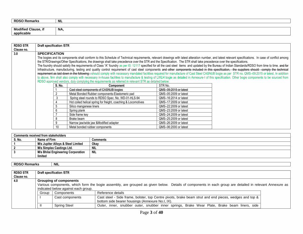
3.0 SPECIFICATION
The bogies and its components shall conform to this Schedule of Technical requirements, relevant drawings with latest alteration number, and latest relevant specifications. In case of conflict among the STR/Drawings/Other Specifications, the drawings shall take precedence over the STR and the Specification. The STR shall take precedence over the specifications. The foundry should satisfy the requirements of Class “A” foundry as per IS :12117 specified for all the cast steel items and updated by the Bureau of Indian Standards/RDSO from time to time. and for Infrastructure, manufacturing, testing and quality control requirement of cast steel components and other components included in this specification, the suppliers should comply the technical requirement as laid down in the following : should comply with necessary mandated facilities required for manufacture of Cast Steel CASNUB bogie as per STR no. QMS–09:2015 or latest. In addition to above, firm shall also comply with necessary in-house facilities to manufacture & testing of LWLH bogie as detailed in Annexure-I of this specification. Other bogie components to be sourced from RDSO approved vendors, duly complying the requirements as referred in relevant STR as detailed below:
S. No. Component STR No.
1 Cast steel components of CASNUB bogies QMS–09:2015 or latest
2 Metal Bonded Rubber components-Elastomeric pad QMS–05:2009 or latest
3 Spring steel rounds to RDSO Spec. No. WD-01-HLS-94 QMS–16:2014 or latest
4 Hot coiled helical spring for freight, coaching & Locomotives QMS–17:2009 or latest
5 Silico manganese liners QMS–22:2009 or latest
6 Spring plank QMS–23:2009 or latest
7 Side frame key QMS–24:2009 or latest
8 Brake beam QMS–25:2009 or latest
9 Narrow jaw/wide jaw &Modified adapter QMS–26:2009 or latest
10 Metal bonded rubber components QMS–06:2000 or latest
Comments received from stakeholders
S. No. Name of Firm Comments
1 M/s Jupiter Alloys & Steel Limited Okay
2 M/s Simplex Castings Ltd. NIL
3 M/s Bhilai Engineering Corporation limited
NIL
RDSO Remarks NIL
RDSO STR Clause no.
Draft specification /STR
4.0 Grouping of components
Various components, which form the bogie assembly, are grouped as given below. Details of components in each group are detailed in relevant Annexure as indicated below against each group.
Group Components Reference details
I Cast components Cast steel - Side frame, bolster, top Centre pivots, brake beam strut and end pieces, wedges and top & bottom side bearer housings (Annexure No.I, IX).
II Spring Steel Outer, inner, snubber outer, snubber inner springs, Brake Wear Plate, Brake beam liners, side

Page 4 of 40
frame/bolster liners & center pivot liners (Annexure No.-II).
III Rubber Components Elastomeric pads and Centre pivot washer, (Annexure No. III).
IV Forged Components & Fasteners
Side frame key, rivets and various types of cotter pins, Huck/Avdel bolts (Annexure No. IV.)
V Fabricated components Various types of steel components, machined, formed, welded and pre assembled like brake beam, spring plank etc. (Annexure No. V).
VI Composite material components
Brake block L type- (Annexure III A).
Comments received from stakeholders
S. No. Name of Firm Comments
1 M/s Jupiter Alloys & Steel Limited NIL
2 M/s Simplex Castings Ltd. NIL
3 M/s Bhilai Engineering Corporation limited
NIL
RDSO Remarks NIL
Modified Clause, if applicable
NA
RDSO STR Clause no.
Draft specification /STR
5.1 Gauging of Bolster & Side frame:
This is to be done on 100% of Bolster and Side frame. Only those castings which are found within the specified dimensions should be taken up for assembly and the rest rejected. Investigations should be made for the reasons of dimensional inaccuracies; causes arrived at, remedial action introduced and defect rectified. Bolster and Side frame should be inspected for all the important dimensions as per the gauging scheme approved by RDSO before offering for inspection or taking up for assembly and results recorded.
Comments received from stakeholders
S. No. Name of Firm Comments
1 M/s Jupiter Alloys & Steel Limited NIL
2 M/s Simplex Castings Ltd. NIL
3 M/s Bhilai Engineering Corporation limited
NIL
RDSO Remarks NIL
Modified Clause, if applicable
NA,
RDSO STR Clause no.
Content of draft specification

Page 5 of 40
5.2 Welding of Liners:
Welding of all the liners on side frame shall be done before taking up side frames for riveting. Welding of liners on bolster shall also be completed before taking them up for assembly. Welding procedure to be followed as indicated in Drawing No. WD – 13012 - S/4 & WD – 13012 – S/5. Following steps have to be taken to ensure proper quality. i) Welds shall be visually inspected for any weld defects. Use of correct electrodes, welding current setting and correct welding procedure has to be ensured.
Welding parameters should be standardized and its implementation ensured. ii) It will be preferable to weld the liners on suitable fixtures so that down hand welding can be ensured. iii) Surface on which liners are welded shall be smooth and flat providing proper seat. Also, Pocket for Side frame liner shall be correctly formed in the casting.
Castings having imperfect pockets on the Side frame shall be rejected. Matching of Side frame – Side frames which have been duly inspected, gauged and passed shall be taken up for assembly. These shall be matched for wheel base according to RDSO’s Drawing No. WD-15021-S/3. Crack detection (Annexure-1) and weld reclamation (Annexure- I A) should also be completed before proceeding to next stage. No welding is permissible after this stage on Side frame as well as on bolster.
Comments received from stakeholders
S. No. Name of Firm Comments
1 M/s Jupiter Alloys & Steel Limited NIL
2 M/s Simplex Castings Ltd. NIL
3 M/s Bhilai Engineering Corporation limited
NIL
RDSO Remarks NIL
Modified Clause, if applicable
NA
RDSO STR Clause no.
Draft specification /STR
5.3 Riveting
After selecting the side frames, these should be taken up for riveting with spring plank. Before riveting it shall be ensured that pop marks are placed on the side frames as per Drawing No. WD-15021-S/3. Stepwise procedure of assembly of H-frame is given below : i) Sideframe holes shall be drilled using accurate jig. ii) The two side frames of same number button head shall only be chosen for assembly of bogie and spring plank should be positioned on a fixture and fastened
rigidly. i) Four holes shown in Item No. 1 in sketch WD-13012-S/4 (spring plank) should be reamed alongwith the sideframe and secured by M-24 fit bolts as per IS:3640. ii) In case any mismatch between spring plank holes and side frame holes is observed visually, detailed check of side frame Dril l Jig and spring plank shall be
made before proceeding further. Riveting should be done as per IS:7215 Group –B. iii) The riveted H-frame shall be gauged and dimensions recorded for diagonals and side frame –to-side frame over pop-marks on the fixture and again after
removing from the fixture as per Para 5.1.
Comments received from stakeholders
S. No. Name of Firm Comments
1 M/s Jupiter Alloys & Steel Limited Okey
2 M/s Simplex Castings Ltd. NIL
3 M/s Bhilai Engineering Corporation NIL
Page 6 of 40
limited
RDSO Remarks NIL
Modified Clause, if applicable
NA
RDSO STR Clause no.
Draft specification /STR
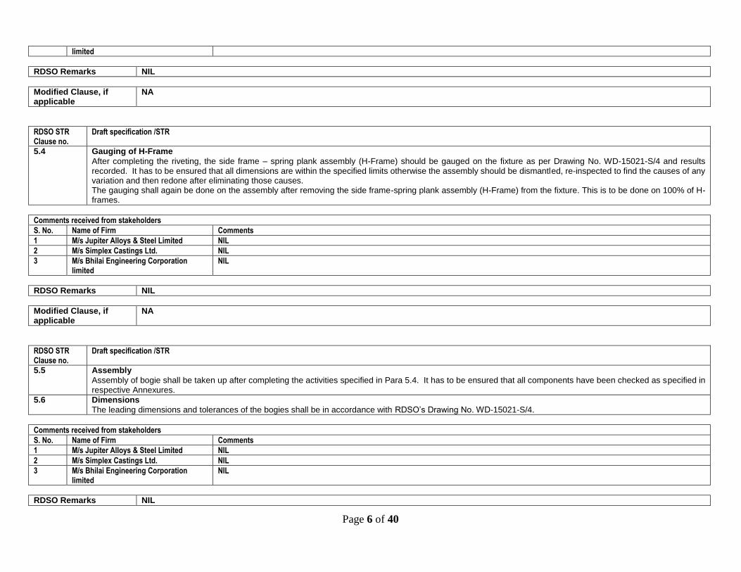
5.4 Gauging of H-Frame
After completing the riveting, the side frame – spring plank assembly (H-Frame) should be gauged on the fixture as per Drawing No. WD-15021-S/4 and results recorded. It has to be ensured that all dimensions are within the specified limits otherwise the assembly should be dismantled, re-inspected to find the causes of any variation and then redone after eliminating those causes. The gauging shall again be done on the assembly after removing the side frame-spring plank assembly (H-Frame) from the fixture. This is to be done on 100% of H-frames.
Comments received from stakeholders
S. No. Name of Firm Comments
1 M/s Jupiter Alloys & Steel Limited NIL
2 M/s Simplex Castings Ltd. NIL
3 M/s Bhilai Engineering Corporation limited
NIL
RDSO Remarks NIL
Modified Clause, if applicable
NA
RDSO STR Clause no.
Draft specification /STR
5.5 Assembly
Assembly of bogie shall be taken up after completing the activities specified in Para 5.4. It has to be ensured that all components have been checked as specified in respective Annexures.
5.6 Dimensions
The leading dimensions and tolerances of the bogies shall be in accordance with RDSO’s Drawing No. WD-15021-S/4.
Comments received from stakeholders
S. No. Name of Firm Comments
1 M/s Jupiter Alloys & Steel Limited NIL
2 M/s Simplex Castings Ltd. NIL
3 M/s Bhilai Engineering Corporation limited
NIL
RDSO Remarks NIL

Page 7 of 40
Modified Clause, if applicable
NA
RDSO STR Clause no.
Draft specification /STR
5.7
Load Testing of Bogie Assembly:
The bogies shall be tested for the loads representing tare, gross load and 50% overload conditions as per the details given below
Test load on bogie pivot in tonne
Tare Gross 50% overload
5.45 T 4526 T 67.90 T
Height of centre pivot in mm
726.5 + 3 - 8
676 + 3 - 8
653 +3 - 8
Scale of this test shall be done as detailed below:
i) 100% checking of Assembled Bogies under tare. ii) 5% checking of Assembled Bogies under gross load and 50% overload. RDSO Inspector may carry out random checks to the extent of 5% of Assembled Bogies under tare, gross load and 50% overload conditions.
Comments received from stakeholders
S. No. Name of Firm Comments
1 M/s Jupiter Alloys & Steel Limited NIL
2 M/s Simplex Castings Ltd. NIL
3 M/s Bhilai Engineering Corporation limited
NIL
RDSO Remarks NIL
Modified Clause, if applicable
NA
RDSO STR Clause no.
Draft specification /STR
5.8 Painting
Each bogie shall be given one coat of Red Oxide Zinc Chromate Primer to Specification IS:2074 followed by one coat of ready mixed paint red Oxide to IS:123. Mating faces of pivots and friction plates will not be painted.
Comments received from stakeholders
S. No. Name of Firm Comments
1 M/s Jupiter Alloys & Steel Limited NIL
2 M/s Simplex Castings Ltd. NIL
3 M/s Bhilai Engineering Corporation limited
NIL
Page 8 of 40
RDSO Remarks NIL
Modified Clause, if applicable
NA
RDSO STR Clause no.
Draft specification /STR
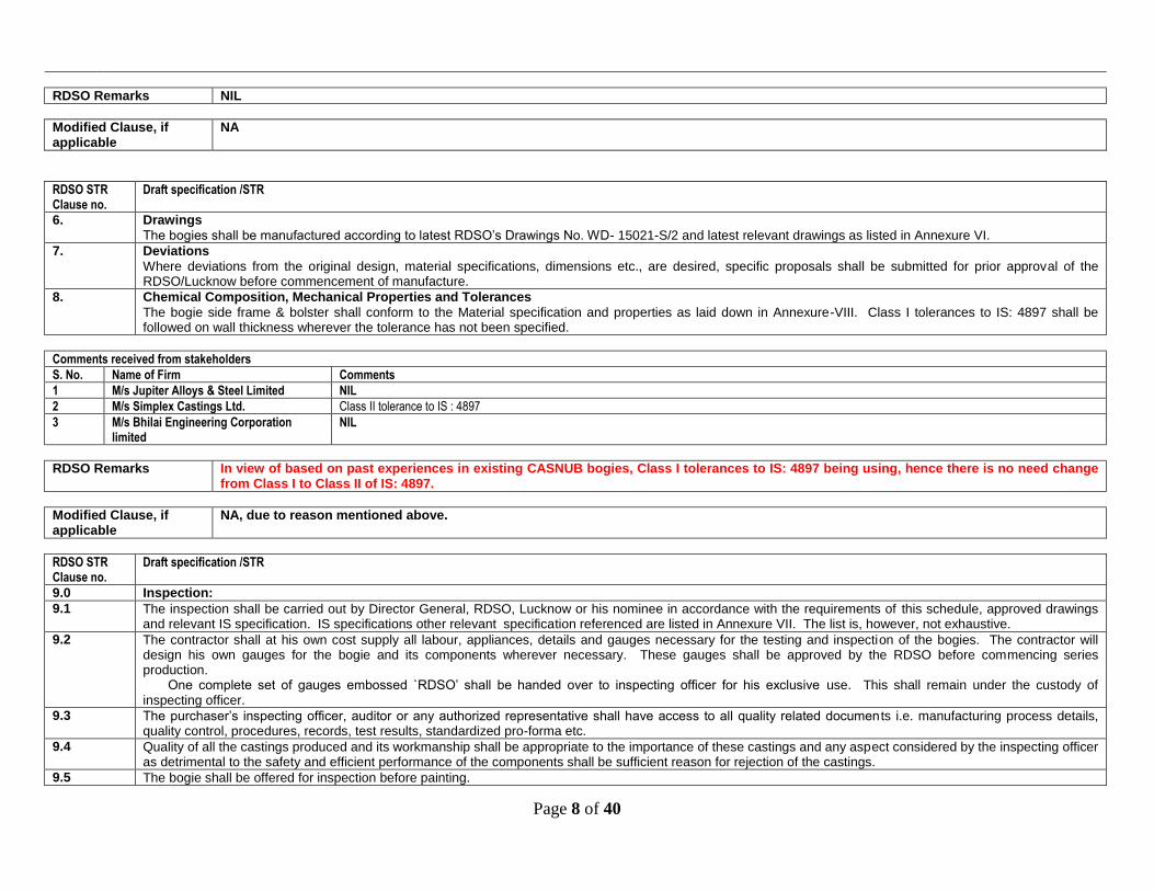
6. Drawings
The bogies shall be manufactured according to latest RDSO’s Drawings No. WD- 15021-S/2 and latest relevant drawings as listed in Annexure VI.
7. Deviations
Where deviations from the original design, material specifications, dimensions etc., are desired, specific proposals shall be submitted for prior approval of the RDSO/Lucknow before commencement of manufacture.
8. Chemical Composition, Mechanical Properties and Tolerances
The bogie side frame & bolster shall conform to the Material specification and properties as laid down in Annexure-VIII. Class I tolerances to IS: 4897 shall be followed on wall thickness wherever the tolerance has not been specified.
Comments received from stakeholders
S. No. Name of Firm Comments
1 M/s Jupiter Alloys & Steel Limited NIL
2 M/s Simplex Castings Ltd. Class II tolerance to IS : 4897
3 M/s Bhilai Engineering Corporation limited
NIL
RDSO Remarks In view of based on past experiences in existing CASNUB bogies, Class I tolerances to IS: 4897 being using, hence there is no need change from Class I to Class II of IS: 4897.
Modified Clause, if applicable
NA, due to reason mentioned above.
RDSO STR Clause no.
Draft specification /STR
9.0 Inspection:
9.1 The inspection shall be carried out by Director General, RDSO, Lucknow or his nominee in accordance with the requirements of this schedule, approved drawings and relevant IS specification. IS specifications other relevant specification referenced are listed in Annexure VII. The list is, however, not exhaustive.
9.2 The contractor shall at his own cost supply all labour, appliances, details and gauges necessary for the testing and inspection of the bogies. The contractor will design his own gauges for the bogie and its components wherever necessary. These gauges shall be approved by the RDSO before commencing series production.
One complete set of gauges embossed `RDSO’ shall be handed over to inspecting officer for his exclusive use. This shall remain under the custody of inspecting officer.
9.3 The purchaser’s inspecting officer, auditor or any authorized representative shall have access to all quality related documen ts i.e. manufacturing process details, quality control, procedures, records, test results, standardized pro-forma etc.
9.4 Quality of all the castings produced and its workmanship shall be appropriate to the importance of these castings and any aspect considered by the inspecting officer as detrimental to the safety and efficient performance of the components shall be sufficient reason for rejection of the castings.
9.5 The bogie shall be offered for inspection before painting.

Page 9 of 40
Comments received from stakeholders
S. No. Name of Firm Comments
1 M/s Jupiter Alloys & Steel Limited NIL
2 M/s Simplex Castings Ltd. NIL
3 M/s Bhilai Engineering Corporation limited
NIL
RDSO Remarks NIL
Modified Clause, if applicable
NA
RDSO STR Clause no.
Draft specification /STR
9.6 Following inspections shall be done by the inspecting officer and results recorded in addition to any other inspection which may be done by him.
9.6.1 Inspection of side frame and bolster – steel castings- shall be governed by Annexure-I and also details given under para on “Bogie assembly requirements” (Para 5). a) Each cast has to be cleared by the Inspecting Officer on the basis of tests indicated at para 8,9, 14 and 15 of Annexure-I.
In addition to above each cast shall also be checked/tested for chemical composition and mechanical properties to conform the requirements/parameters as given in Annexure –VIII.
b) Tests indicated at Para 14, 17, 18 and 19 are in the nature of audit check and reflect on the quality of manufacturing process.
9.6.2 Gauging of H frame shall be done on 5% of the frames assembled, as per para 5.4.
Comments received from stakeholders
S. No. Name of Firm Comments
1 M/s Jupiter Alloys & Steel Limited NIL
2 M/s Simplex Castings Ltd. NIL
3 M/s Bhilai Engineering Corporation limited NIL
RDSO Remarks NIL
Modified Clause, if applicable
NA
RDSO STR Clause no.
Draft specification /STR
9.6.3 All components as per Annexure-IX to be inspected as per details given in the respective Annexures. This is to be done by random sampling on components received by Bogie Manufacturer. If any sample among the test pieces drawn fails, then double the number of test pieces drawn earlier shall be again selected and tested. If the `Double’ sample passes the tests, lot shall be considered acceptable. Should any of the samples fail, the complete lot shall be rejected.
Comments received from stakeholders
S. No. Name of Firm Comments
1 M/s Jupiter Alloys & Steel Limited NIL
2 M/s Simplex Castings Ltd. NIL
3 M/s Bhilai Engineering Corporation NIL
Page 10 of 40
limited
RDSO Remarks NIL
Modified Clause, if applicable
NA,
RDSO STR Clause no.
Draft specification /STR
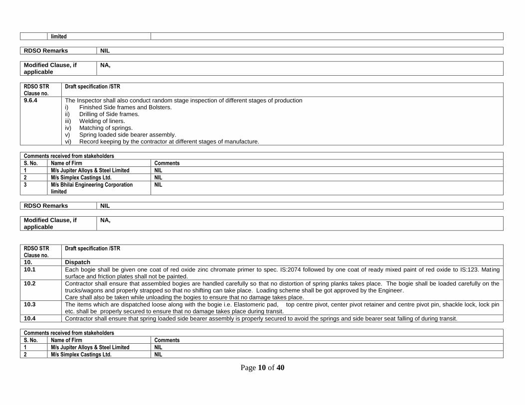
9.6.4 The Inspector shall also conduct random stage inspection of different stages of production i) Finished Side frames and Bolsters. ii) Drilling of Side frames. iii) Welding of liners. iv) Matching of springs. v) Spring loaded side bearer assembly. vi) Record keeping by the contractor at different stages of manufacture.
Comments received from stakeholders
S. No. Name of Firm Comments
1 M/s Jupiter Alloys & Steel Limited NIL
2 M/s Simplex Castings Ltd. NIL
3 M/s Bhilai Engineering Corporation limited
NIL
RDSO Remarks NIL
Modified Clause, if applicable
NA,
RDSO STR Clause no.
Draft specification /STR
10. Dispatch
10.1 Each bogie shall be given one coat of red oxide zinc chromate primer to spec. IS:2074 followed by one coat of ready mixed paint of red oxide to IS:123. Mating surface and friction plates shall not be painted.
10.2 Contractor shall ensure that assembled bogies are handled carefully so that no distortion of spring planks takes place. The bogie shall be loaded carefully on the trucks/wagons and properly strapped so that no shifting can take place. Loading scheme shall be got approved by the Engineer. Care shall also be taken while unloading the bogies to ensure that no damage takes place.
10.3 The items which are dispatched loose along with the bogie i.e. Elastomeric pad, top centre pivot, center pivot retainer and centre pivot pin, shackle lock, lock pin etc. shall be properly secured to ensure that no damage takes place during transit.
10.4 Contractor shall ensure that spring loaded side bearer assembly is properly secured to avoid the springs and side bearer seat falling of during transit.
Comments received from stakeholders
S. No. Name of Firm Comments
1 M/s Jupiter Alloys & Steel Limited NIL
2 M/s Simplex Castings Ltd. NIL

Page 11 of 40
3 M/s Bhilai Engineering Corporation limited
NIL
RDSO Remarks NIL
Modified Clause, if applicable
NA
RDSO STR Clause no.
Draft specification /STR
11.0 As Made” Drawings
11.1 The bogie suppliers shall supply tracings on cloth of “As Made” drawings followed in the manufacture of the bogies where deviations from the original design, material specifications and dimensions etc. have been adopted
Comments received from stakeholders
S. No. Name of Firm Comments
1 M/s Jupiter Alloys & Steel Limited NIL
2 M/s Simplex Castings Ltd. NIL
3 M/s Bhilai Engineering Corporation limited
NIL
RDSO Remarks NIL
RDSO STR Clause no.
Draft specification /STR
12 Process for approval, vendor registration and vendor progression
All manufactures seeking approval for supply of LWLH25 bogie assembly covered under this specification, to Indian Railways shall follow the procedure outlined below:
12.1 Manufacturers shall apply online to RDSO, fulfilling requirements applicable for online application for fresh registration. This shall include requisite fees, compliance of STR/specification and other requirements as covered in relevant applicable latest guidelines/procedures as applicable for fresh registration of any item. Manufacturers should have valid certificate for Class “A” foundries (IS:12117) issued by RDSO on date of application and satisfy all requirements of Class A foundries (IS:12117) specified and updated by Bureau of Indian Standards from time to time and other infrastructural facilities as laid down in Para 3 of this specification.
12.2 Manufacturers should have valid certificate for Class “A” foundries (IS:12117) issued by RDSO on date of application and satisfy all requirements of Class A foundries (IS:12117) specified and updated by Bureau of Indian Standards from time to time and other infrastructural facilities as laid down in Para 3 of this specification. Manufacturers shall apply online to RDSO, fulfilling requirements applicable for online application for fresh registration. This shall include requisite fees, compliance of STR/specification and other requirements as covered in relevant applicable latest guidelines/procedures as applicable for fresh registration of any item.
12.3 The manufacturer shall also submit (to RDSO) the hard copies documented procedure of manufacture, methoding system for castings, as-cast drawings, details of castings quality check to be followed, gauging scheme, quality conformance testing arrangements, assembly procedure, other relevant details along with QAP which will be followed during manufacture. The QAP shall be verified during course of STR verification and capability assessment.
O On receipt of application and documents submitted by the firm shall be scrutinized this information, the capability or otherwise of the manufacturer shall be judged by RDSO. If the information submitted by the firm found to be inadequate firm shall be intimated for necessary compliance. In case the manufacturer is considered capable, a team of RDSO officials shall visit the manufacturer’s premises to verify the manufacturing, testing and other facilities to manufacture the product conforming to this specification and submit a report.
Comments received from stakeholders
S. No. Name of Firm Comments

Page 12 of 40
1 M/s Jupiter Alloys & Steel Limited Okay
2 M/s Simplex Castings Ltd. NIL
3 M/s Bhilai Engineering Corporation limited
Para 12.3 : This sentence may be written as “On receipt, application and documents submitted by the firm shall be scrutinized by RDSO “
RDSO Remarks Incorporated.
Modified Clause, if applicable
The manufacturer shall also submit (to RDSO) the hard copies documented procedure of manufacture, methoding system for castings, as-cast drawings, details of castings quality check to be followed, gauging scheme, quality conformance testing arrangements, assembly procedure, other relevant details along with QAP which will be followed during manufacture. The QAP shall be verified during course of STR verification and capability assessment. On receipt, application and documents submitted by the firm shall be scrutinized by RDSO. If the information submitted by the firm found to be inadequate firm shall be intimated for necessary compliance. In case the manufacturer is considered capable, a team of RDSO officials shall visit the manufacturer’s premises to verify the manufacturing, testing and other facilities to manufacture the product conforming to this specification and submit a report.
RDSO STR Clause no.
Draft specification /STR
12.4 Based on this report, a decision shall be arrived at and conveyed to the manufacturer regarding permission to manufacture a prototype bogie to this specification. Based on the report of team, a decision shall be arrived at and conveyed to the manufacturer regarding permission to manufacture two nos. of prototype bogies to this specification/STR along with provisionally approved QAP.
12.5 Manufacturing of proto samples of bogies shall be done strictly as per relevant drawings, specification and provisionally approved QAP. The infrastructure requirement and specified manufacturing modalities for casting, testing etc shall be complied strictly as per the details given in Annexure-I. The manufacturer shall produce two sets of castings of bogie assembly complete with integrated test blocks & annealing lugs, (separately cast sample for smaller castings). Duly cleaned and shot blasted castings shall be offered for examination to RDSO in the as-cast and heat treated condition. The components fitted on proto bogies shall be duly inspected by concerned inspecting authority. Quality conformance shall be checked with respect to the requirements of this STR. All tests listed in Annexure-I of the specification shall be done. Components shall be checked as per the scheme given in their respective relevant Annexures.
During prototype testing if any sample fails/not meeting requirements, manufacturer has to review the process and report has to be submitted to approving authority (ED/wagon or ED/QA) for consideration.
12.6 Based on the satisfactory prototype test results and manufacturing facilities found to be meeting the requirements in respect of infrastructure and other requirements as covered in specification (Para 12.3 above), the firm shall be considered for approval as a RDSO vendor for Developmental Orders as an approved source with Part II status for manufacture and supply of LWLH25 bogie as per the relevant and applicable RDSO procedure (s) for the same.
12.7 On receipt of any order for manufacture, the manufacturer shall submit (to RDSO) the documented procedure of manufacture, methoding system for castings, as-cast drawings, details of castings quality check to be followed, gauging scheme, quality conformance testing arrangements, assembly procedure, other relevant details and QAP which will be followed during manufacture. Manufacture of LWLH25 bogie shall be done in accordance with an approved/re-affirmed QAP only.
Comments received from stakeholders
S. No. Name of Firm Comments
1 M/s Jupiter Alloys & Steel Limited Okay
2 M/s Simplex Castings Ltd. NIL
3 M/s Bhilai Engineering Corporation limited
This sentence may be written as “Based on the report of team of RDSO officials decision shall be arrived at and conveyed to the manufacturer regarding permission to manufacture two nos. of prototype bogies to this specification/STR along with provisionally approved QAP”.
RDSO Remarks Incorporated.
Modified Clause, if applicable
Based on the report of team of RDSO officials, decision shall be arrived at and conveyed to the manufacturer regarding permission to manufacture two nos. of prototype bogies to this specification/STR along with provisionally approved QAP.

Page 13 of 40
RDSO STR Clause no.
Draft specification /STR
12.8 A manufacturer shall be considered for up-gradation of their status from Part-II to Part-I only when: A manufacturer shall be considered for up-gradation from “RDSO vendors for Developmental order” to “RDSO approved vendor” for manufacture and supply of LWLH25 bogie after satisfactory supply & field performance for a minimum period of one year or equivalent equipment months for a minimum quantity 500 nos of bogies or as specified in the relevant RDSO document, in accordance to latest RDSO document no. QO-D-7.1-11.
12.8.1 The firm has successfully supplied minimum 1500 nos. of these LWLH25 bogies.
12.8.2 1500 nos. LWLH25 bogies supplied by the firm have given satisfactory field performance without any adverse feedback reported by Zonal Railways/Users for a period to be in service for minimum period of one year or from 15 months from date of issue of last inspection certificate. The firm has to apply to RDSO for up gradation of their status from “RDSO vendors for Developmental order” to “RDSO approved vendor” and the same shall be processed as per relevant procedures applicable time to time. The firm has to apply to RDSO for up gradation from Part II to Part I Status and the same shall be processed up by the as per relevant procedures applicable time to time.
Comments received from stakeholders
S. No. Name of Firm Comments
1 M/s Jupiter Alloys & Steel Limited Para 12.8: effective date of RDSO document no. QO-D-7.1-11 is not mentioned.
2 M/s Simplex Castings Ltd. NIL
3 M/s Bhilai Engineering Corporation limited
Para 12.8: This sentence may be written as “A manufacturer shall be considered from “RDSO approved vendors for Developmental order” to “RDSO approved vendor” for manufacture and supply of LWLH25 bogie after satisfactory supply & field performance for a minimum period of one year or equivalent equipment months for a minimum quantity 500 nos. of bogies or as specified in the relevant RDSO document, in accordance to latest RDSO document no. QO-D-7.1-11”. Para 12.8.2: This sentence may be written as “After supply of 500Nos. of bogies the firm has to apply to RDSO for up gradation of their status from “RDSO vendors for Developmental order” to “RDSO approved vendor” and the same shall be processed as per relevant procedures applicable time to time.
RDSO Remarks 1. Comments of M/s Jupiter Alloys & Steel Limited for Para 12.8 has been already mentioned for latest version. 2. Comments of M/s Bhilai Engineering Corporation limited for Para 12.8 incorporated. 3. There is no need of change as the upgradation criteria is already defined in Para 12.8 and upgradation procedure shall be in
accordance with QO-D-7.1-11(latest).
Modified Clause, if applicable
12.8 A manufacturer shall be considered from “RDSO approved vendors for Developmental order” to “RDSO approved vendor” for manufacture and supply of LWLH25 bogie after satisfactory supply & field performance for a minimum period of one year or equivalent equipment months for a minimum quantity 500 nos. of bogies or as specified in the relevant RDSO document, in accordance to latest RDSO document no. QO-D-7.1-11. 12.8.2 N.A. due to reason mentioned above.
RDSO STR Clause no.
Draft specification /STR
13 Quality Assurance Programme :
All activities relating to quality assurance shall be the responsibility of Quality Manager who shall form the interface with the RDSO inspecting officer. The relevant records for maintaining quality for each of the following items shall be maintained and made available to the inspecting officer. 12.8 Pattern and Core Boxes 12.9 Sand Preparation 12.10 Moulding and Core making 12.11 Assembly of Core 12.12 Metal Pouring 12.13 Heat treatment 12.14 Visual examination 12.15 Gauging scheme

Page 14 of 40
12.16 Stagewise manufacturing quality checks/test during bogie assembly and its components. 12.17 System to ensure quality of all components used in assembling a bogie in addition to casting. 12.18 System for disposal of defective components identified during various stages of manufacture and implementation of QAP, so that such components are not
mixed up with lot being offered for inspection. 12.19 Records of Internal Quality Program for future references/investigations. 12.20 Records to identify the manufacturing details/tests of components with Serial Number marked on components. 12.21 Records of the mechanical and chemical test reports covering the heats representing the purchased castings.The period for which records will be preserved
can be decided between supplier and inspecting authority.
Comments received from stakeholders
S. No. Name of Firm Comments
1 M/s Jupiter Alloys & Steel Limited NIL
2 M/s Simplex Castings Ltd. NIL
3 M/s Bhilai Engineering Corporation limited
NIL
RDSO Remarks NIL
Modified Clause, if applicable
Quality Assurance Programme :
All activities relating to quality assurance shall be the responsibility of Quality Manager who shall form the interface with the RDSO inspecting officer. The relevant records for maintaining quality for each of the following items shall be maintained and made available to the inspecting officer. 13.1 Pattern and Core Boxes 13.2 Sand Preparation 13.3 Moulding and Core making 13.4 Assembly of Core 13.5 Metal Pouring 13.6 Heat treatment 13.7 Visual examination 13.8 Gauging scheme 13.9 Stagewise manufacturing quality checks/test during bogie assembly and its components. 13.10 System to ensure quality of all components used in assembling a bogie in addition to casting. 13.11 System for disposal of defective components identified during various stages of manufacture and implementation of QAP, so that such
components are not mixed up with lot being offered for inspection. 13.12 Records of Internal Quality Program for future references/investigations. 13.13 Records to identify the manufacturing details/tests of components with Serial Number marked on components. 13.14 Records of the mechanical and chemical test reports covering the heats representing the purchased castings. The period for which records will
be preserved can be decided between supplier and inspecting authority.
RDSO STR Clause no.
Draft specification /STR
14
Quality Audit
This part covers the aspects of manufacture and quality assurance which will be audited by RDSO at specified periodicity. The audit shall be conducted at two levels i.e. one at the level of RDSO’s Inspecting Engineers and the other by officers nominated by DG(Wagon) RDSO , Lucknow. The former will be conducted at a periodicity not exceeding 3 months and the later at least once a year. The report of the audit shall be submitted to DG(Wagon) and DG(I&L), RDSO, Lucknow.
Comments received from stakeholders
Page 15 of 40
S. No. Name of Firm Comments
1 M/s Jupiter Alloys & Steel Limited NIL
2 M/s Simplex Castings Ltd. NIL
3 M/s Bhilai Engineering Corporation limited
NIL
RDSO Remarks NIL
Modified Clause, if applicable
NA
RDSO STR Clause no.
Draft specification /STR
15
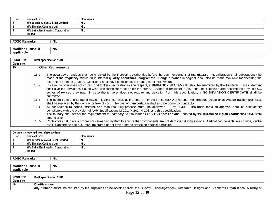
Other Requirements :
15.1 The accuracy of gauges shall be checked by the Inspecting Authorities before the commencement of manufacture. Recalibration shall subsequently be made at the frequency stipulated in internal Quality Assurance Programme. Gauge drawings in original, shall also be made available for checking the
tolerances of these gauges. Contractor shall have sufficient sets of gauges for his own use. 15.2 In case the offer does not correspond to this specification in any respect, a DEVIATION STATEMENT shall be submitted by the Tenderer. This statement
shall give the deviations clause wise with technical reasons for the same. Change in drawings, if any, shall be explained and accompanied by THREE copies of revised drawings. In case the tenderer does not require any deviation from this specification, a NO DEVIATION CERTIFICATE shall be
submitted. 15.3 The bogie components found having illegible markings at the time of fitment in Railway Workshops, Maintenance Depot or at Wagon Builder premises,
shall be replaced by the contractor free of cost. The cost of transportation shall also be borne by contractor. 15.4 All contractor’s foundries, material and manufacturing process must be approved by RDSO. The basis for such approval sha ll be satisfactory
compliance with the provision of AAR Specifications M-201, M-202, M-203, and this specification. The foundry shall satisfy the requirements for category “A” foundries (IS:12117) specified and updated by the Bureau of Indian Standards/RDSO from
time to time. 15.5 Contractor shall have a proper housekeeping system to ensure that components are not damaged during storage. Critical components like springs, centre
pivot, elastomeric pad etc. must be stored under cover and be protected against corrosion.
Comments received from stakeholders
S. No. Name of Firm Comments
1 M/s Jupiter Alloys & Steel Limited NIL
2 M/s Simplex Castings Ltd. NIL
3 M/s Bhilai Engineering Corporation limited
NIL
RDSO Remarks NIL
Modified Clause, if applicable
NA
RDSO STR Clause no.
Draft specification /STR
16 Clarifications
Any further clarification required by the supplier can be obtained from the Director General(Wagon), Research Designs and Standards Organisation, Ministry of

Page 16 of 40
Railways, Manak Nagar Lucknow – 226 011 ( India ).
Comments received from stakeholders
S. No. Name of Firm Comments
1 M/s Jupiter Alloys & Steel Limited NIL
2 M/s Simplex Castings Ltd. NIL
3 M/s Bhilai Engineering Corporation limited
NIL
RDSO Remarks NIL
Modified Clause, if applicable
NA
RDSO STR Clause no.
Draft specification /STR
17
Warranty
The firm shall stand warrantee for complete bogie/ components, unless otherwise specified in the specification of individual component/ sub-assembly, for a period of 72 months from the date of manufacture or 60 months from the date of fitment/commissioning of the wagon, whichever is earlier. In case of pre-mature failure of any component/sub-assembly, the firm will be liable to make free replacement of failed component/sub-assembly to the depot where failure has been reported within reasonable time.
Comments received from stakeholders
S. No. Name of Firm Comments
1 M/s Jupiter Alloys & Steel Limited NIL
2 M/s Simplex Castings Ltd. NIL
3 M/s Bhilai Engineering Corporation limited
NIL
RDSO Remarks NIL
Modified Clause, if applicable
NA,
RDSO STR Clause no.
Draft specification /STR
18
All the provisions contained in RDSO’s ISO procedures laid down in document No. QO-D-7.1-11 dated 19/07/2016 (titled “Vendor-Changes in approved status”) and subsequent versions/amendments thereof, shall be binding and applicable on the successful vendor/vendors in the contracts floated by Railways to maintain quality of products supplied to Railways.
Comments received from stakeholders
S. No. Name of Firm Comments
1 M/s Jupiter Alloys & Steel Limited NIL
2 M/s Simplex Castings Ltd. NIL
3 M/s Bhilai Engineering Corporation limited
NIL

Page 17 of 40
RDSO Remarks NIL
Modified Clause, if applicable
NA,
RDSO STR Clause no.
Draft specification /STR
ANNEXURE –I (Sheet 1 of 8) CAST COMPONENTS
1 Requirements of steel castings and manufacturing process:
All basic foundry processes e.g. moulding, core making, heat treatment, fettling, shot blasting, heat treatment and weld reclamation shall be done in house with adequate facilities and infrastructure for all steel castings. All steel melting and refinement must be performed with the use of an Electric Arc Furnace only.
Comments received from stakeholders
S. No. Name of Firm Comments
1 M/s Jupiter Alloys & Steel Limited NIL
2 M/s Simplex Castings Ltd. NIL
3 M/s Bhilai Engineering Corporation limited
NIL
RDSO Remarks NIL
Modified Clause, if applicable
NA
RDSO STR Clause no.
Draft specification /STR
ANNEXURE –I (Sheet 1 of 8) CAST COMPONENTS
1.1
Ladle analysis
The ladle analysis of steel when carried out by spectrometer to determine the percentage carbon, manganese, phosphorus, sulphur, silicon etc shall conform to chemical compositions as per AAR B+ material as detailed in Annexure-VIII.
Comments received from stakeholders
S. No. Name of Firm Comments
1 M/s Jupiter Alloys & Steel Limited NIL
2 M/s Simplex Castings Ltd. NIL
3 M/s Bhilai Engineering Corporation limited
NIL
RDSO Remarks NIL
Modified Clause, if applicable
NA
RDSO STR Clause no.
Draft specification /STR
Page 18 of 40
ANNEXURE –I (Sheet 1 of 8) CAST COMPONENTS
1.2
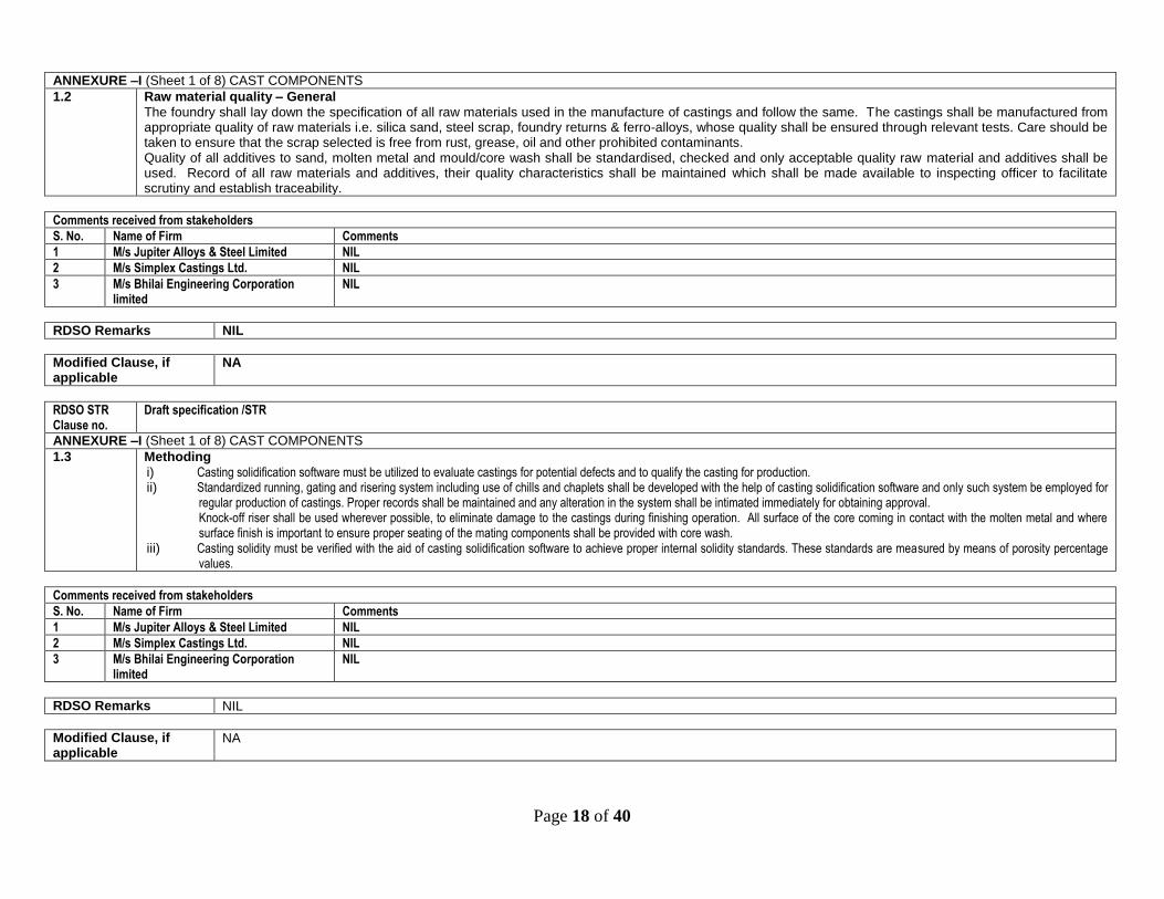
Raw material quality – General
The foundry shall lay down the specification of all raw materials used in the manufacture of castings and follow the same. The castings shall be manufactured from appropriate quality of raw materials i.e. silica sand, steel scrap, foundry returns & ferro-alloys, whose quality shall be ensured through relevant tests. Care should be taken to ensure that the scrap selected is free from rust, grease, oil and other prohibited contaminants. Quality of all additives to sand, molten metal and mould/core wash shall be standardised, checked and only acceptable quality raw material and additives shall be used. Record of all raw materials and additives, their quality characteristics shall be maintained which shall be made available to inspecting officer to facilitate scrutiny and establish traceability.
Comments received from stakeholders
S. No. Name of Firm Comments
1 M/s Jupiter Alloys & Steel Limited NIL
2 M/s Simplex Castings Ltd. NIL
3 M/s Bhilai Engineering Corporation limited
NIL
RDSO Remarks NIL
Modified Clause, if applicable
NA
RDSO STR Clause no.
Draft specification /STR
ANNEXURE –I (Sheet 1 of 8) CAST COMPONENTS
1.3
Methoding
i) Casting solidification software must be utilized to evaluate castings for potential defects and to qualify the casting for production. ii) Standardized running, gating and risering system including use of chills and chaplets shall be developed with the help of casting solidification software and only such system be employed for
regular production of castings. Proper records shall be maintained and any alteration in the system shall be intimated immediately for obtaining approval. Knock-off riser shall be used wherever possible, to eliminate damage to the castings during finishing operation. All surface of the core coming in contact with the molten metal and where surface finish is important to ensure proper seating of the mating components shall be provided with core wash.
iii) Casting solidity must be verified with the aid of casting solidification software to achieve proper internal solidity standards. These standards are measured by means of porosity percentage values.
Comments received from stakeholders
S. No. Name of Firm Comments
1 M/s Jupiter Alloys & Steel Limited NIL
2 M/s Simplex Castings Ltd. NIL
3 M/s Bhilai Engineering Corporation limited
NIL
RDSO Remarks NIL
Modified Clause, if applicable
NA

Page 19 of 40
RDSO STR Clause no.
Draft specification /STR
ANNEXURE –I (Sheet 1 of 8) CAST COMPONENTS
1.4
Moulding
Moulding shall be carried out by employing either of the following process given below: (a) High Pressure Moulding Line with Intensive Mixture for Green sand mould with Automatic Moisture Control and addition of Binder in fixed rates
OR
(b) Articulated Mixer (continuous type) with fume extraction facility & Compaction Table for No-Bake System.
Mould hardness shall be minimum 85 and the same should be uniform at all the surfaces (Within ± 5% at the entire surface including vertical) so as to get good dimensional accuracy in castings. For High pressure moulding line mould hardness shall be in range of 85 and the same should be uniform at all the surfaces (Within ± 5% at the entire surface including vertical),and for No – Bake System scratch hardness of mould shall be minimum 60 and same should be uniform at all the surfaces so as to get good dimensional accuracy in castings. Suitable arrangement shall be made in the mould to obtain manufacturer’s identity, month and year of manufacture, casting Sr. No., Drg. No. for each side frame and bolster casting, center pivot top and brake beam strut casting and other castings as indicated in drawings. Two annealing lugs of size 25 X 25 X 8 mm shall be provided in all castings to facilitate micro-examination. To facilitate mechanical testing and chemical analysis, at least 3 castings per batch shall have integrated test piece from which samples for tests shall be prepared. All moulds shall be given a `wash’ of appropriate quality on the entire surface coming in contact with the molten metal to ensure proper surface finish and undesirable metal/mould reaction.
Comments received from stakeholders
S. No. Name of Firm Comments
1 M/s Jupiter Alloys & Steel Limited Okay
2 M/s Simplex Castings Ltd. In case of no – bake system, scratch hardness should be checked, acid phenolic system should have 80 min. and alkalinic phenol should have min. 55 hardness.
3 M/s Bhilai Engineering Corporation limited
NIL
RDSO Remarks Based on experience gain during course of development of LWLH25 bogie at various bogie manufacturers, it was observed that for no-bake system scratch hardness of mould shall be minimum 60 instead of 55 to get good dimensional accuracy in castings.
Modified Clause, if applicable
NA, due to reason mentioned above.
RDSO STR Clause no.
Draft specification /STR
ANNEXURE –I (Sheet 1 of 8) CAST COMPONENTS
1.5
Sand Preparation & Sand Lab
The foundry shall lay down the characteristics of all sand mixes i.e. moulding sand, core sand, facing sand and shall have proper arrangement for sand drying & preparation of sand mix of consistent quality and the characteristics of each batch shall be checked to ensure conformance to standard arrived at by the foundry. Sand mix of unacceptable quality shall not be processed. The foundry shall be equipped with a full-fledged sand testing lab. Testing facilities shall comprise incoming sand tests like active clay content, acid demand value, loss on ignition, mechanical grading (grain fineness number) and sand mix tests like moisture content, green & dry strength, permeability, shatter index, surface hardness, scratch hardness, bench life, strip time, hot distortion, high temperature properties.

Page 20 of 40
Comments received from stakeholders
S. No. Name of Firm Comments
1 M/s Jupiter Alloys & Steel Limited NIL
2 M/s Simplex Castings Ltd. NIL
3 M/s Bhilai Engineering Corporation limited
NIL
RDSO Remarks NIL
Modified Clause, if applicable
NA,
RDSO STR Clause no.
Draft specification /STR
ANNEXURE –I (Sheet 1 of 8) CAST COMPONENTS
1.6
Core-Making
All cores shall be produced by No-bake process for which continuous mixer with compaction table/ batch mixer shall be available in-house. Preferably single core shall be used in each mould to achieve the desired quality of castings.
Comments received from stakeholders
S. No. Name of Firm Comments
1 M/s Jupiter Alloys & Steel Limited NIL
2 M/s Simplex Castings Ltd. NIL
3 M/s Bhilai Engineering Corporation limited NIL
RDSO Remarks NIL
Modified Clause, if applicable
NA,
RDSO STR Clause no.
Draft specification /STR
ANNEXURE –I (Sheet 1 of 8) CAST COMPONENTS
1.7 Melting
A sufficient carbon boil must be accomplished with a minimum 20 point carbon reduction. Double slag process for proper removal of sulphur and phosphorus shall be followed. Argon Purging may be carried out to ensure freedom from harmful gases. Ladle pre-heating at 600 to 700°C shall be carried out. Temperature checking in Furnace and in Ladle by Immersion Pyrometer shall be done before pouring in Mould.
Comments received from stakeholders
S. No. Name of Firm Comments
1 M/s Jupiter Alloys & Steel Limited NIL
2 M/s Simplex Castings Ltd. NIL
3 M/s Bhilai Engineering Corporation limited
NIL
Page 21 of 40
RDSO Remarks NIL
Modified Clause, if applicable
NA
RDSO STR Clause no.
Draft specification /STR
ANNEXURE –I (Sheet 1 of 8) CAST COMPONENTS
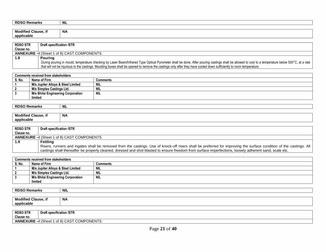
1.8 Pouring
During pouring in mould, temperature checking by Laser Beam/Infrared Type Optical Pyrometer shall be done. After pouring castings shall be allowed to cool to a temperature below 500°C, at a rate that will not be injurious to the castings. Moulding boxes shall be opened to remove the castings only after they have cooled down sufficiently to room temperature.
Comments received from stakeholders
S. No. Name of Firm Comments
1 M/s Jupiter Alloys & Steel Limited NIL
2 M/s Simplex Castings Ltd. NIL
3 M/s Bhilai Engineering Corporation limited
NIL
RDSO Remarks NIL
Modified Clause, if applicable
NA
RDSO STR Clause no.
Draft specification /STR
ANNEXURE –I (Sheet 1 of 8) CAST COMPONENTS
1.9 Fettling
Risers, runners and ingates shall be removed from the castings. Use of knock-off risers shall be preferred for improving the surface condition of the castings. All castings shall thereafter be properly cleaned, dressed and shot blasted to ensure freedom from surface imperfections, loosely adherent sand, scale etc.
Comments received from stakeholders
S. No. Name of Firm Comments
1 M/s Jupiter Alloys & Steel Limited NIL
2 M/s Simplex Castings Ltd. NIL
3 M/s Bhilai Engineering Corporation limited
NIL
RDSO Remarks NIL
Modified Clause, if applicable
NA
RDSO STR Clause no.
Draft specification /STR
ANNEXURE –I (Sheet 1 of 8) CAST COMPONENTS

Page 22 of 40
1.10
Heat treatment
All heat treatment furnaces shall be equipped with adequate number of pyrometers and recorders. Facility for output chart indicating time verses temperature shall be available for each furnace. Plan for placement of castings in the furnace shall be standardised to ensure uniformity of heat treatment for each casting of a particular batch and the same shall be followed without any deviation. Castings for heat treatment shall be cleaned / dressed sufficiently to respond the heat treatment. The castings shall be normalized or normalized tempered as detailed below to achieve properties as detailed in Annexure-VIII. i) Process of Normalizing shall be followed in following order:
Heat to proper uniform temperature above the transformation range and hold for the proper time to achieve complete austenization and to refine the grain structure.
Withdraw from the furnace and cool in still air until temperature of entire casting reach below the 371 degree Celsius (tempering temperature).
ii) Process of Normalized and tempered shall be followed in following order:
Heat to proper uniform temperature above the transformation range and hold for the proper time to achieve complete austenization and to refine the grain structure.
Withdraw from the furnace and cool in still air until entire casting temperature reach at least below 38 degree below tempering temperature.
Temper by reheating to proper uniform temperature below the transformation range, but not less than 316 Degree Celsius and hold for the required time. Remove castings from the furnace and allow it to cool at desired rate. All the stages of heat treatment with various temperature ranges of processes shall be clearly brought out in QAP. Inspecting Authority shall examine it with actual heat treatment process being followed during quality audit.
Comments received from stakeholders
S. No. Name of Firm Comments
1 M/s Jupiter Alloys & Steel Limited NIL
2 M/s Simplex Castings Ltd. NIL
3 M/s Bhilai Engineering Corporation limited
NIL
RDSO Remarks NIL
Modified Clause, if applicable
NA
RDSO STR Clause no.
Draft specification /STR
ANNEXURE –I (Sheet 1 of 8) CAST COMPONENTS
1.11
Heat-Treatment Documentation
The manufacturer is required to develop and document heat-treating standards that describe the processes, process control procedures, and record keeping requirements. These documents are to be presented and reviewed as part of the Foundry Approval Process and are intended to ensure that products are properly heat treated. Furnace temperatures for heat treatment shall be controlled by pyrometers having associated recording equipment that produce time-temperature record charts that are identified by date and furnace number. A log sheet for each load of castings heat treated (batch) should show all information pertinent to each heat-treat load including the following:
Type of casting
Prescribed heat treatment
Serial numbers and the heat numbers of the castings

Page 23 of 40
Actual time of heat treatment.
Pyrometers shall be calibrated every 3 months. Records of time-temperature charts, furnace log sheets, and pyrometer calibrations will be maintained for 3 years and available to the purchaser upon request.
Comments received from stakeholders
S. No. Name of Firm Comments
1 M/s Jupiter Alloys & Steel Limited NIL
2 M/s Simplex Castings Ltd. NIL
3 M/s Bhilai Engineering Corporation limited
NIL
RDSO Remarks NIL
Modified Clause, if applicable
NA
RDSO STR Clause no.
Draft specification /STR
ANNEXURE –I (Sheet 1 of 8) CAST COMPONENTS
2.0
Visual examination
All castings shall be examined visually and in the event of doubt by using a magnifying glass. Final examination has to be done by magnetic particle testing method as indicated in Para 7.2. The castings shall be free from harmful surface defects, inclusions, sand fusion, blow holes, folds, cracks, misruns, surface imperfections, unfused chaplets and porosity. Castings having freedom from defects shall only be processed for machining and assembly.
Comments received from stakeholders
S. No. Name of Firm Comments
1 M/s Jupiter Alloys & Steel Limited NIL
2 M/s Simplex Castings Ltd. NIL
3 M/s Bhilai Engineering Corporation limited
NIL
RDSO Remarks NIL
Modified Clause, if applicable
NA
RDSO STR Clause no.
Draft specification /STR
ANNEXURE –I (Sheet 1 of 8) CAST COMPONENTS
3.0
Weld reclamation
In case defects are observed in the castings, a sketch showing the location, approximate dimension and nature shall be prepared. Weld repair possibility shall be considered after careful examination of the castings on a case to case basis and specific approval of inspecting officer shall be obtained. The defect must be removed completely and its elimination ensured prior to weld repair. The weld reclamation shall be carried out as per procedure outlined at Annexure-IA. All castings reclaimed by welding shall be subjected to normalizing in the same manner as outlined for castings manufactured in the first instance.
Comments received from stakeholders

Page 24 of 40
S. No. Name of Firm Comments
1 M/s Jupiter Alloys & Steel Limited NIL
2 M/s Simplex Castings Ltd. NIL
3 M/s Bhilai Engineering Corporation limited
NIL
RDSO Remarks NIL
Modified Clause, if applicable
NA
RDSO STR Clause no.
Draft specification /STR
ANNEXURE –I (Sheet 1 of 8) CAST COMPONENTS
4.0
Disposal of rejected castings
All castings which have been rejected either by the internal inspecting officer or by purchaser’s inspecting officer shall be promptly marked with a red paint as ‘REJECTED’, segregated at approximately earmarked area and shall be defected at the earliest opportunity. Record of such castings including Sr. No. shall be maintained.
Comments received from stakeholders
S. No. Name of Firm Comments
1 M/s Jupiter Alloys & Steel Limited NIL
2 M/s Simplex Castings Ltd. NIL
3 M/s Bhilai Engineering Corporation limited
NIL
RDSO Remarks NIL
Modified Clause, if applicable
NA
RDSO STR Clause no.
Draft specification /STR
ANNEXURE –I (Sheet 1 of 8) CAST COMPONENTS
5.0
Feed back mechanism
The foundry shall have a mechanism for identifying and control of defects through feedback obtained from inspecting and quali ty control personnel. Suitable remedial action shall be introduced in the manufacturing process with the consent of purchaser’s inspecting officer wherever the same is necessary. Record of all improvements, modifications, and alterations shall be maintained to assess their effect and subsequent scrutiny. A report listing these shall be submitted to Engineer half yearly interval.
Comments received from stakeholders
S. No. Name of Firm Comments
1 M/s Jupiter Alloys & Steel Limited NIL
2 M/s Simplex Castings Ltd. NIL
3 M/s Bhilai Engineering Corporation limited
NIL

Page 25 of 40
RDSO Remarks NIL
Modified Clause, if applicable
NA
RDSO STR Clause no.
Draft specification /STR
ANNEXURE –I (Sheet 1 of 8) CAST COMPONENTS
6.0
Tests for chemical composition and mechanical properties i) Sufficient nos. of test bars for side frames and bolster shall be cast integral with the components. Test bars of other casting shall be cast separately.
ii) Chemical analysis each heat for each type of casting is to be recorded. iii) Test bars for each heat & heat treatment batch of the same grade will be tested for mechanical properties. Test results shall be recorded.
iv) Re-tests will be governed by the relevant IS Specification. Sufficient samples shall be retained for re-tests or cross checks of chemical and mechanical properties when required by inspecting officer. These shall be retained for period of 2 years.
Comments received from stakeholders
S. No. Name of Firm Comments
1 M/s Jupiter Alloys & Steel Limited NIL
2 M/s Simplex Castings Ltd. NIL
3 M/s Bhilai Engineering Corporation limited
NIL
RDSO Remarks NIL
Modified Clause, if applicable
NA
RDSO STR Clause no.
Draft specification /STR
ANNEXURE –I (Sheet 1 of 8) CAST COMPONENTS
7.0
Non-destructive tests
The following non-destructive tests shall be carried out
7.1 Radiographic Tests
One side frame and one bolster casting in every 100 bogies or part thereof shall be subjected to radiographic examination for the initial supply of 300 bogies. Frequency of testing shall be reduced to 1 in 500 bogies after the successful supply of initial 300 bogie sets. Different contracts will be treated as if in continuation irrespective of contract size-unless there is a gap of 3 months between execution of two consecutive contracts or there is a major design change. The sketches showing locations for radiographic examination are enclosed WX 16003A (for bolster) and WX 16003B (for side frame). All radiographs shall clearly reveal the image of penetration at appropriate locations to enable correct interpretation of radiographic classification. In no case sensitivity of radiographs would be below 2%. Standard of radiographic examination at different locations shall be as under :
Location as shown in Sketches WX 16003A (for bolster) and WX 16003B (for side frame)
Accepted level of severity as per ASTM-446-81 or E-71 (no hot tears or cracks are permissible)
Side frame : Location 2 Gas porosity - level 3

Page 26 of 40
Bolster : Locations 1 & 2 Sand inclusion – level 3 Shrinkage - level 3 in categories CB & CD Shrinkage -level 4 in categories CA & CC
Side frame : Locations 5 and 3 Gas porosity - level 4 Sand inclusion – level 4 Shrinkage - level 4 in categories CB & CD Shrinkage -level 4 in categories CA & CC
Bolster : Location 3
Side frame : Locations 1 and 4 Gas porosity - level 5 Sand inclusion – level 5 Shrinkage - level 5 in categories CB & CD. Shrinkage - level 5 in categories CA & CC
Comments received from stakeholders
S. No. Name of Firm Comments
1 M/s Jupiter Alloys & Steel Limited NIL
2 M/s Simplex Castings Ltd. NIL
3 M/s Bhilai Engineering Corporation limited
NIL
RDSO Remarks NIL
Modified Clause, if applicable
NA
RDSO STR Clause no.
Draft specification /STR
ANNEXURE –I (Sheet 1 of 8) CAST COMPONENTS
7.2
Magnetic particle test
Magnetic particle test shall be conducted on all sideframe and Bolster casting at locations indicated in sketches no. WX 16003A (for bolster) and WX 16003B (for side frame) in accordance with IS:3703. The equipment consumables shall meet RDSO specification M&C/NDT/15/91 and M&C/NDT/8/91. No cracks are permitted. The cracks up to a depth of 2 mm shall be ground and blended with surrounding surfaces. Deeper cracks shall be rectified as per Annexure IA. Magnaflux test shall again be done after grinding to ensure removal of crack. Inspecting officer shall witness 5% of the bogies checked.
Comments received from stakeholders
S. No. Name of Firm Comments
1 M/s Jupiter Alloys & Steel Limited NIL
2 M/s Simplex Castings Ltd. NIL
3 M/s Bhilai Engineering Corporation limited
NIL
RDSO Remarks NIL
Modified Clause, if applicable
NA
Page 27 of 40
RDSO STR Clause no.
Draft specification /STR
ANNEXURE –I (Sheet 1 of 8) CAST COMPONENTS
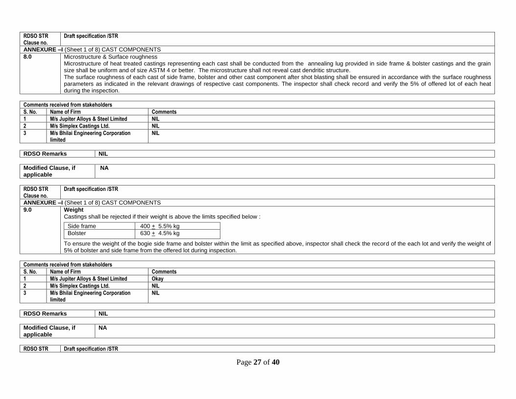
8.0
Microstructure & Surface roughness Microstructure of heat treated castings representing each cast shall be conducted from the annealing lug provided in side frame & bolster castings and the grain size shall be uniform and of size ASTM 4 or better. The microstructure shall not reveal cast dendritic structure. The surface roughness of each cast of side frame, bolster and other cast component after shot blasting shall be ensured in accordance with the surface roughness parameters as indicated in the relevant drawings of respective cast components. The inspector shall check record and verify the 5% of offered lot of each heat during the inspection.
Comments received from stakeholders
S. No. Name of Firm Comments
1 M/s Jupiter Alloys & Steel Limited NIL
2 M/s Simplex Castings Ltd. NIL
3 M/s Bhilai Engineering Corporation limited
NIL
RDSO Remarks NIL
Modified Clause, if applicable
NA
RDSO STR Clause no.
Draft specification /STR
ANNEXURE –I (Sheet 1 of 8) CAST COMPONENTS
9.0
Weight
Castings shall be rejected if their weight is above the limits specified below :
To ensure the weight of the bogie side frame and bolster within the limit as specified above, inspector shall check the record of the each lot and verify the weight of 5% of bolster and side frame from the offered lot during inspection.
Side frame 400 + 5.5% kg
Bolster 630 + 4.5% kg
Comments received from stakeholders
S. No. Name of Firm Comments
1 M/s Jupiter Alloys & Steel Limited Okay
2 M/s Simplex Castings Ltd. NIL
3 M/s Bhilai Engineering Corporation limited
NIL
RDSO Remarks NIL
Modified Clause, if applicable
NA
RDSO STR Draft specification /STR

Page 28 of 40
Clause no.
ANNEXURE –I (Sheet 1 of 8) CAST COMPONENTS
10.0
Load testing
Castings shall be selected at random for load test by the inspector. Different contracts will be treated as if in continuation irrespective of contract size-unless there is a gap of 3 months between executions of two consecutive contracts or there is a major design change. In such cases, tests will be carried out as if on a new contract. Casting will be checked by magnetic particle test and at corners and radii with dye-penetrant test both before and after the load tests. A shallow crack after the load test which can be removed by grinding off to a depth of 1 mm will not be treated as a failure. In case of other cracks two more castings from the same lot shall be tested. If any one of the latter castings fails in the load test, the lot stands rejected. In case of rejection, the manufacturer shall review his foundry practices and take whatever steps necessary to satisfy the inspector of the adequacy of the process of manufacture.
10.1 Proof load Testing Proof load & ultimate load Testing of bolster & Side frame The bogie bolster and side frame shall comply with following static proof tests as detailed in below para 10.1.1 and 10.1.2 in accordance with AAR M – 202 and M – 203. All bogie manufacturer shall have in house facilities for static proof load testing of bogie side frame and bolster with necessary fixture and suitable load deflection measuring device to carry out the tests as detailed below. An indicative details of necessary fixtures, load testing arrangement and measuring fixture required for conduct load testing of bolster and side frame are shown in the Annexure-X:
10.1.1 Static proof load test for Bogie Bolster
The loading of the bogie bolster for various loads as indicated in table below with their location [as shown in the sketch at Annexure-X] are to be carried out and corresponding values of deflection and permanent as mentioned set to be observed. The specified allowable values of deflection and permanent set are specified against the each test load.
Load S. No.
Type of test load for bolster (location as given in Annexure )
Amount of load to be applied (T)
Permissible values of deflection/set
Allowable deflection (mm)
Allowable permanent set (mm)
a) Transverse loading (F3) 45.80 2.54 3.60
b) Transverse loading (F3) 87.10 0.635 0.64
c) Side bearing loading(F2) 67.60 1.6
d) Side bearing loading (F2) 108.90 0.635
e) Vertical loading at centre plate (F1) 67.60 2.31 3.30
f) Vertical loading at centre plate (F1) 130.70 0.635 0.64
g) Vertical loading(Ultimate) at center plate (F1)
239.50 (Minimum)
The testing procedure and sequence for application of above loads (Listed above) to be applied as per details given below: a) Transverse load for deflection
Load to 9100 kg 9.10t and then release gradually to 2250 kg 2.50t.
Set dial gauge to zero reading
Load then to 45800 kg 45.80t.
Note the deflection resulted.
Release the load to 2250 kg 2.50t and set the dial gauge to zero, if required. b) Transverse load for permanent set
Load to 87100 kg 87.10t
Release load to 2250 kg 2.50t

Page 29 of 40
Note the resulted set. c) Vertical – side bearing load for deflection
Load to 9100 kg and then release gradually to 2250 kg
Set dial gauge to zero reading
Load up to 67600 kg
Note the resulted deflection.
Release the load to 2250 kg and set the dial gauge to zero, if required. d) Vertical – side bearing load for permanent set
Load to 108900 kg
Release to 2250 kg
Note resulted set. e) Vertical – centre pivot load for deflection
Load to 9100 kg 9.10t and then release gradually to 2250 kg 2.50t
Set dial gauge to zero reading
Load up to 67600 kg 67.60t
Note the resulted deflection.
Release the load to 2250 kg 2.50t and set the dial gauge to zero, if required. f) Vertical – centre pivot load for permanent set
Load to 130700 kg 130.70t
Release to 2250 kg 2.50t
Note resulted set. g) Ultimate load
Load to 239,500 kg 239.50t and then check for cracks etc.
10.1.2 Static proof load test for Bogie Side frame
The loading of the bogie side frame for various loads as indicated in table below with their location [as shown in the sketch at Annexure-X (sheet 2of 2)] are to be carried out and corresponding values of deflection and permanent set as mentioned to be observed. The specified allowable values of deflection and permanent set are specified against the each test load.
Load S. No.
Type of test load for side frame (location as given in Annexure )
Amount of load to be applied (T)
Permissible values of deflection/set
Allowable deflection (mm)
Allowable permanent (mm)
a) Transverse loading (F2) 15.90 3.3 3.60
b) Transverse loading (F2) 27.20 0.35
c) Vertical loading at plank seat (F1) 53.30 1.6 1.80
d) Vertical loading at plank seat (F1) 102.0 0.35
e) Vertical loading at plank seat (Elastic limit) (F1) 96.40 (Minimum)
f) Vertical loading at plank seat(Ultimate Load) (F1) 283.50 (Minimum)
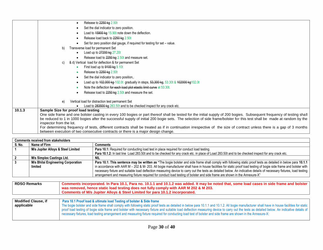
The testing procedure and sequence for application of above loads (Listed above) to be applied as per details given below:
a) Transverse load for deflection
First load up to 2250 kg 9.10t
Page 30 of 40
Release to 2250 kg 2.50t
Set the dial indicator to zero position.
Load to 15900 kg 15.90t note down the deflection.
Release load back to 2250 kg 2.50t
Set for zero position dial gauge, if required for testing for set – value.
b) Transverse load for permanent Set
Load up to 27200 kg 27.20t
Release load to 2250 kg 2.50t and measure set.
c) & d) Vertical load for deflection & for permanent Set
First load up to 9100 kg 9.10t
Release to 2250 kg 2.50t
Set the dial indicator to zero position,.
Load up to 102,000 kg 102.0t gradually in steps, 53,300 kg, 53.30t & 102000 kg102.0t
Note the deflection for each load plot elastic limit curve at 53.30t.
Release load to 2250 kg 2.50t and measure the set.
e) Vertical load for distraction test permanent Set
Load to 283500 kg 283.50t and to be checked inspect for any crack etc.
10.1.3 Sample Size for proof load testing
One side frame and one bolster casting in every 100 bogies or part thereof shall be tested for the initial supply of 200 bogies. Subsequent frequency of testing shall be reduced to 1 in 1000 bogies after the successful supply of initial 200 bogie sets. The selection of side frame/bolster for this test shall be made at random by the inspector from the lot. For determining frequency of tests, different contracts shall be treated as if in continuation irrespective of the size of contract unless there is a gap of 3 months between execution of two consecutive contracts or there is a major design change.
Comments received from stakeholders
S. No. Name of Firm Comments
1 M/s Jupiter Alloys & Steel Limited Para 10.1: Required for conducting load test in place required for conduct load testing. Para 10.1.2: In last line Load 283.50t and to be checked for any crack etc. in place of Load 283.50t and to be checked inspect for any crack etc.
2 M/s Simplex Castings Ltd. NIL
3 M/s Bhilai Engineering Corporation limited
Para 10.1: This sentence may be written as “The bogie bolster and side frame shall comply with following static proof tests as detailed in below para 10.1.1 in accordance with AAR M – 202 & M- 203. All bogie manufacturer shall have in house facilities for static proof load testing of bogie side frame and bolster with necessary fixture and suitable load deflection measuring device to carry out the tests as detailed below. An indicative details of necessary fixtures, load testing arrangement and measuring fixture required for conduct load testing of bolster and side frame are shown in the Annexure-X”
RDSO Remarks Comments incorporated. In Para 10.1, Para no. 10.1.1 and 10.1.2 was added. It may be noted that, some load cases in side frame and bolster was removed, hence static load testing does not fully comply with AAR M 202 & M 203. Comments of M/s Jupiter Alloys & Steel Limited for para 10.1.2 incorporated.
Modified Clause, if applicable
Para 10.1 Proof load & ultimate load Testing of bolster & Side frame The bogie bolster and side frame shall comply with following static proof tests as detailed in below para 10.1.1 and 10.1.2. All bogie manufacturer shall have in house facilities for static proof load testing of bogie side frame and bolster with necessary fixture and suitable load deflection measuring device to carry out the tests as detailed below. An indicative details of necessary fixtures, load testing arrangement and measuring fixture required for conducting load test of bolster and side frame are shown in the Annexure-X:

Page 31 of 40
Last line of Para 10.1.2 : Load to 283.50t and to be checked for any crack etc.
RDSO STR Clause no.
Draft specification /STR
ANNEXURE –I (Sheet 1 of 8) CAST COMPONENTS
11.0 Sectioning test
11.1 Castings subjected to destruction tests shall be sectioned to establish moulding practices. Sketches showing the location for sectioning are enclosed as No. WX16004A WX17009A (for sectioning location of bolster) & WX16004B WX 17009B (for sectioning location of side frame). Sample size of this test shall be same as para 10.1.3.
11.2 Following items are to be specifically checked : a) Wall thickness b) Solidity
11.3 Permitted variation in wall thickness of the castings is as given below :
Wall thickness dimension Permissible variation
6 mm upto 11 mm not including 11 mm + 3 mm to –1 mm
11 mm up to not including 20 mm + 3 mm to –2 mm
11.4 Solidity should be checked by etching the sectioned surface over ¼ thickness as distributed in the sketches.
11.5 Any failures in these parameters will indicate deficiencies in the manufacturing process. One more casting shall be taken and subjected to load test as per para 10 and sectioning test as explained in this para. If any deficiency is again found then the foundry shall be subjected to complete review of manufacturing process to find out the cause of such failure and manufacturing shall be recommended after eliminating such cause.
11.6 A report on the load testing and sectioning test (para 10 & 11) shall be sent to the DG (Wagon)
Comments received from stakeholders
S. No. Name of Firm Comments
1 M/s Jupiter Alloys & Steel Limited Okay
2 M/s Simplex Castings Ltd. NIL
3 M/s Bhilai Engineering Corporation limited
NIL
RDSO Remarks NIL
Modified Clause, if applicable
NA
RDSO STR Clause no.
Draft specification /STR
ANNEXURE –I (Sheet 1 of 8) CAST COMPONENTS
12.0 Wall thickness check shall be made at specified locations as per mentioned in enclosed sketches of side frame and bolster nos. WX16004A WX 17009A and WX16004B WX 17009B on 5% the castings using ultrasonic thickness gauge. This gauge may be obtained from any RDSO approved ultrasonic equipment manufacturer. Any rejection will mean defect in pattern, core, mould setting or process and appropriate investigation shall be made.
Comments received from stakeholders
S. No. Name of Firm Comments
1 M/s Jupiter Alloys & Steel Limited Okay

Page 32 of 40
2 M/s Simplex Castings Ltd. NIL
3 M/s Bhilai Engineering Corporation limited
NIL
RDSO Remarks NIL
Modified Clause, if applicable
NA
RDSO STR Clause no.
Draft specification /STR
ANNEXURE – I A
1. This procedure covers the steps to be followed for weld repair of casting defects considered repairable by the inspecting officer. 2. Before conducting weld reclamation, a sketch showing the nature, size and location of defects shall be prepared and written permission of inspecting officer
shall be obtained on case to case basis. 3. While decision regarding weld reclamation shall be taken by the inspecting officer, the following guidelines shall be followed. 3.1 Through thickness cracks shall not be considered for welding. 3.2 Misrun shall not be repaired by welding. 3.3 Defects which are located at vulnerable locations (zone 1 & Zone 2 as specified in enclosed sketches Nos WX 16005A and WX 16005B) shall not be
repaired if their depth exceeds 25% of the wall thickness. At other locations defects upto 50% of the wall thickness shall be considered for weld reclamation.
3.4 The total length of the weld seam in one casing shall not exceed 100 mm and no single weld seam length shall exceed 50 mm. If more than 2 castings reach or exceed the stipulated defect limit, audit by inspector shall be necessary.
3.5 All castings repaired by welding shall be normalized. 3.6 The welding shall be conducted by qualified welders with valid certificate.
Repair procedure
The extent of crack of defect shall be judged by visual or magnetic particle examination. Use of crack depth meter is also recommended for precise crack depth determination. The defect shall be eliminated by pneumatic gauging and its elimination ensured by magnetic/dye penetrant testing. Appropriated shaped groove shall be prepared with the help of portable pencil grinder and entire surface cleaned properly to ensure freedom from heavy scale, oil, grease, paint, dirt etc. RDSO approved class E2 electrodes to RDSO specification no. IRSM 28/2012 shall be used for welding repairs. Current, polarity and OCV shall be as per
recommendation of the electrode manufacturer. Welding shall be done in down hand position maintaining an interpass temp of 250-300 Deg. C, de-slagging and peening after each run. The Weldments shall be examined for presence of cracks by dye penetrant testing. Weldments free form cracks shall be considered acceptable.
Comments received from stakeholders
S. No. Name of Firm Comments
1 M/s Jupiter Alloys & Steel Limited NIL
2 M/s Simplex Castings Ltd. NIL
3 M/s Bhilai Engineering Corporation limited
NIL
RDSO Remarks NIL
Modified Clause, if NA
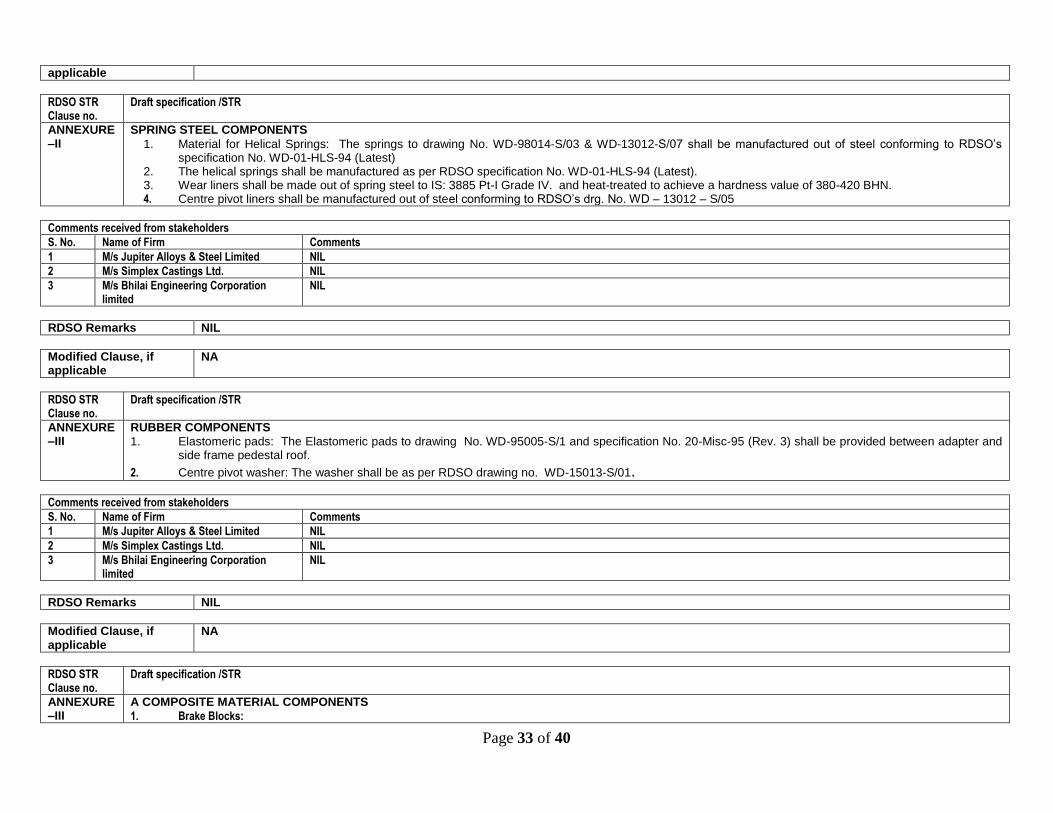
Page 33 of 40
applicable
RDSO STR Clause no.
Draft specification /STR
ANNEXURE –II
SPRING STEEL COMPONENTS
1. Material for Helical Springs: The springs to drawing No. WD-98014-S/03 & WD-13012-S/07 shall be manufactured out of steel conforming to RDSO’s specification No. WD-01-HLS-94 (Latest)
2. The helical springs shall be manufactured as per RDSO specification No. WD-01-HLS-94 (Latest). 3. Wear liners shall be made out of spring steel to IS: 3885 Pt-I Grade IV. and heat-treated to achieve a hardness value of 380-420 BHN. 4. Centre pivot liners shall be manufactured out of steel conforming to RDSO’s drg. No. WD – 13012 – S/05
Comments received from stakeholders
S. No. Name of Firm Comments
1 M/s Jupiter Alloys & Steel Limited NIL
2 M/s Simplex Castings Ltd. NIL
3 M/s Bhilai Engineering Corporation limited
NIL
RDSO Remarks NIL
Modified Clause, if applicable
NA
RDSO STR Clause no.
Draft specification /STR
ANNEXURE –III
RUBBER COMPONENTS
1. Elastomeric pads: The Elastomeric pads to drawing No. WD-95005-S/1 and specification No. 20-Misc-95 (Rev. 3) shall be provided between adapter and side frame pedestal roof.
2. Centre pivot washer: The washer shall be as per RDSO drawing no. WD-15013-S/01.
Comments received from stakeholders
S. No. Name of Firm Comments
1 M/s Jupiter Alloys & Steel Limited NIL
2 M/s Simplex Castings Ltd. NIL
3 M/s Bhilai Engineering Corporation limited
NIL
RDSO Remarks NIL
Modified Clause, if applicable
NA
RDSO STR Clause no.
Draft specification /STR
ANNEXURE –III
A COMPOSITE MATERIAL COMPONENTS
1. Brake Blocks:

Page 34 of 40
‘K’ type brake block shall be manufactured as per the RDSO Drawing no. WD-15023-S/1 and Specification No. WD-14-ABR-2007, Amendment No. 2 of May-2015 by the manufactures. The drawing quoted above is for reference. The manufacturers should submit their own drawing for approval. ‘L’ type brake block shall be manufactured as per the RDSO Drawing no. CONTR-9404-S/11 Alt-6 and Specification No. WD-13-ABR-2006, Amendment No. 2 of Sept-2016 by the manufactures. The drawing quoted above is for reference. The manufacturers should submit their own drawing for approval.
Comments received from stakeholders
S. No. Name of Firm Comments
1 M/s Jupiter Alloys & Steel Limited Okay
2 M/s Simplex Castings Ltd. NIL
3 M/s Bhilai Engineering Corporation limited
NIL
RDSO Remarks NIL
Modified Clause, if applicable
NA
RDSO STR Clause no.
Draft specification /STR
ANNEXURE –IV
FORGED COMPONENTS AND FASTENERS
S. No. Drg. No. Description Specification
1. WD-15013-S/01 Centre Pivot Pin IS: 2062 or latest
2. WD-15013-S/01 Shackle lock IS: 2004
3. WD-15013-S/01 Lock pin IS: 1875
4. --- Rivets – 12, 20 and 24 dia. IS: 1929, IS: 1148
5. WD-94068-S/1 Bulb cotter IS: 1079-73 St-42 or IRS: M-41-74
6. --- Split pins IS: 549
7. Hexagonal Fit bolt (M-24) with washer and castle nut. IS: 2232, IS:3640, IS: 2016
8. WD-13012-S/4, item –2 Side frame key IS: 1875 Cl. IV
Comments received from stakeholders
S. No. Name of Firm Comments
1 M/s Jupiter Alloys & Steel Limited NIL
2 M/s Simplex Castings Ltd. NIL
3 M/s Bhilai Engineering Corporation limited
NIL
RDSO Remarks NIL
Modified Clause, if applicable
NA
RDSO STR Clause no.
Draft specification /STR
ANNEXURE –V
FABRICATED COMPONENTS
S.No. Description Drg. with Alt. No. Specification

Page 35 of 40
1. Equalizing lever with bushes CONTR.9404/S/10,Item 1,2,8,9 & 10
IS:2062 E250 A
IS:5517
2. Bogie End Full Rod CONTR.9404-S/10, Item -4 IS:2062 E250 A 3. Bogie Brake Push rod CONTR.9404-S/10, Item -3 IS:2062 E250 A 4. Pin 28 dia. with washer & bulb cotter CONTR.9404-S/10, Item -6 IS:2062 E250 A 5. Pin 40 dia. with washer & bulb cotter CONTR.9404-S/10, Item -7 IS:2062 E250 A 6. Washer (OD 56, ID 31 dia. X 5 thk ) --- IS:2062 E250 A 7. Washer (OD 90, ID 50 X 8 thk ) ---- IS:2062 E250 A 8. Brake beam WD – 16006 – S/1 CONTR - 9404- S/17 IS:2062& IS:1030 Gr.280 – 520W
9. Brake Shoe Key W/BG-6150 IS: 3885 OR IS: 3195
10. Side frame friction liner WD – 13012 – S/4 Item 5 IS: 3885
11. Bolster liner WD – 13012 – S/5 Item 2 IS: 3885
12. Spring Plank WD-13012-S/4 Item 1 IS: 5986 Fe 510
13. Centre pivot liner WD-13012-S/5 Item 1 IRS : R 65 – 78
14. Washer WD – 15013 – S/01 Item 2 IS:2062 & IS :5192
Comments received from stakeholders
S. No. Name of Firm Comments
1 M/s Jupiter Alloys & Steel Limited Okay
2 M/s Simplex Castings Ltd. NIL
3 M/s Bhilai Engineering Corporation limited
NIL
RDSO Remarks NIL
Modified Clause, if applicable
NA
RDSO STR Clause no.
Draft specification /STR
ANNEXURE –VI
(A) LIST OF CONSTRUCTION DRAWINGS
Drawing No.
Description
WD-15021-S/1 Index
WD-15021-S/2 General Arrangement With ‘K’ class Bearing
WD-15021-S/3 Cast Steel Side frame (With ‘K’ class Narrow Pedestal Jaw)
WD-13012-S/4 Bogie details
WD-13012-S/5 (Sheet 1 of 2) Cast steel bolster (With Integrated 14’’ Centre Pivot Bottom)
WD-13012-S/5 (Sheet 2 of 2) Cast steel bolster (With Integrated 14’’ Centre Pivot Bottom)
WD-13012-S/6 Cast Steel Wedge (For Nested Springs)
WD-98014-S/03 Outer & Inner Spring Details
WD-13012-S/7 Nested Snubber Spring Details
CONTR-9404-S/09 Bogie Brake Gear Arrangement.
CONTR-9404-S/10 Bogie Brake Gear Details
WD – 15023 – S/01 CONTR-9404-S/11
Composition Brake Block

Page 36 of 40
WD-15020-S/01 Wheel and Axle Assembly (With ‘K’ class Journal)
WD-15021-S/04 Leading Dimensions And Tolerances
WD-12008-S/01 Spring Loaded Side Bearer Assembly & Details
WD-13012-S/10 Marking Scheme For Cast Steel Side frame & Bolster
WD-89006-S/1 BG, MG & NG coil spring drawing codes
WD – 16006 – S/1 CONTR - 9404- S/17
Brake Beam
WD-95005-S/1 Elastomeric Pad
WD-13012-S/11 Bogie Assembly Procedure
WD-15013-S/01 Centre Pivot Top (14’’ Dia.)
WD-15020-S/03 Narrow Jaw ‘K’ Class Adapter
WD-13012-S/04 (Item – 02) Side Frame Key
WD-13012-S/04 (Item – 04) Side frame key bolt, Nut with Spring Washer and Split pin
List of part Drawings
WD-94068-S/1 Bulb cotter
W/BG-6150 Brake shoe key
Comments received from stakeholders
S. No. Name of Firm Comments
1 M/s Jupiter Alloys & Steel Limited Okay
2 M/s Simplex Castings Ltd. NIL
3 M/s Bhilai Engineering Corporation limited
NIL
RDSO Remarks NIL
Modified Clause, if applicable
NA
RDSO STR Clause no.
Draft specification /STR
ANNEXURE –VII
SPECIFICATION FOR BOGIE MANUFACTURE BOGIE
Annexure VIII of this STR Specification of material for side frame, Bolster & Top & bottom housing of spring loaded side bearer
IS: 1030 (Gr. 280-520 W) Brake beam (end piece & strut), Top & bottom housing of spring loaded side bearer
IS:276 Gr. 1 Wedge
IS:3885 Pt. I Gr. 4 SF friction liner, Bolster friction liner ,Brake beam wear plate ,Brake wear plate Brake block key
IS:5986-2011 Spring plank
IS:2062 Push rod, pull rod & lever
IS:1929 ;IS:1148 Rivets
IS:2585 & IS: 549 Key bolt with 4.0 dia. Split pin
IS:2074 Primer paint
IS:123 IS: 05 Red oxide paint Middle Brunswick green paint

Page 37 of 40
IS:9595 Welding
IS:1079-73 St. 42/IRS-M 41-74 Bulb cotter
IS:2004 forged components
IS:7215 Riveting
IS:3195 Helical springs
IS: 7318 Pt. I Qualification for welders
IS:4897 Deviation for untoleranced dimensions and mass of steel casting
IS:2102 Allowable deviations for dimensions without specified tolerance
IS:3469 Pt. I, II & III Weight, quantity and dimensioning tolerances on forgings
IS:3073 Surface finish
IS:3640 Hexagonal fit bolts
IS:5530 Code of procedure for rectification of steel castings by metal arc welding process
ASTM-E-446-84 or E-71 Standard for radiographic analysis
AAR-M-201, M – 202, M - 203 Centre pivot Top, side frame , bolster
IS:5517 Bushes & pins
IRS – R - 65 - 78 Centre pivot liners
Comments received from stakeholders
S. No. Name of Firm Comments
1 M/s Jupiter Alloys & Steel Limited Okay
2 M/s Simplex Castings Ltd. NIL
3 M/s Bhilai Engineering Corporation limited
NIL
RDSO Remarks NIL
Modified Clause, if applicable
NA
RDSO STR Clause no.
Draft specification /STR
ANNEXURE –VIII
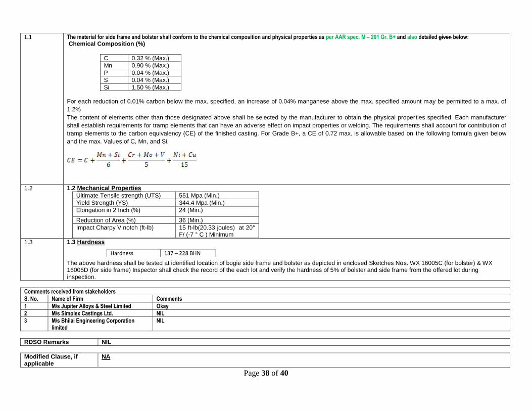
Page 38 of 40
1.1
The material for side frame and bolster shall conform to the chemical composition and physical properties as per AAR spec. M – 201 Gr. B+ and also detailed given below: Chemical Composition (%)
C 0.32 % (Max.)
Mn 0.90 % (Max.)
P 0.04 % (Max.)
S 0.04 % (Max.)
Si 1.50 % (Max.)
For each reduction of 0.01% carbon below the max. specified, an increase of 0.04% manganese above the max. specified amount may be permitted to a max. of
1.2%
The content of elements other than those designated above shall be selected by the manufacturer to obtain the physical properties specified. Each manufacturer
shall establish requirements for tramp elements that can have an adverse effect on impact properties or welding. The requirements shall account for contribution of
tramp elements to the carbon equivalency (CE) of the finished casting. For Grade B+, a CE of 0.72 max. is allowable based on the following formula given below
and the max. Values of C, Mn, and Si.
1.2 1.2 Mechanical Properties
Ultimate Tensile strength (UTS) 551 Mpa (Min.)
Yield Strength (YS) 344.4 Mpa (Min.)
Elongation in 2 Inch (%) 24 (Min.)
Reduction of Area (%) 36 (Min.)
Impact Charpy V notch (ft-lb) 15 ft-lb(20.33 joules) at 20° F/ (-7 ° C ) Minimum
1.3 1.3 Hardness
The above hardness shall be tested at identified location of bogie side frame and bolster as depicted in enclosed Sketches Nos. WX 16005C (for bolster) & WX 16005D (for side frame) Inspector shall check the record of the each lot and verify the hardness of 5% of bolster and side frame from the offered lot during inspection.
Hardness 137 – 228 BHN
Comments received from stakeholders
S. No. Name of Firm Comments
1 M/s Jupiter Alloys & Steel Limited Okay
2 M/s Simplex Castings Ltd. NIL
3 M/s Bhilai Engineering Corporation limited
NIL
RDSO Remarks NIL
Modified Clause, if applicable
NA

Page 39 of 40
RDSO STR Clause no.
Draft specification /STR
ANNEXURE –IX List of components and their Inspection Procedure
Annexure-IX
1. Centre pivot & its assembly Annexure –IX (sheet 2 of 15 )
2. Manganese steel castings- wedges Annexure –IX (sheet 4 of 15 )
3. Outer, inner, snubber springs Annexure –IX (sheet 5 of 15 )
4. Liners Annexure –IX (sheet 6 of 15 )
5 Brake block key Annexure –IX (sheet 7 of 15 )
6. Rubber components Annexure –IX (sheet 8 of 15 )
7. Spring plank Annexure –IX (sheet 9 of 15 )
8. Other forged components- Sideframe key, bulb cotter, hexagonal fit bolt, shackle lock Annexure –IX (sheet 10 of 15 )
9. Brake beam Annexure –IX (sheet 11 & 12 of 15 )
10. Centre pivot retaining ring Annexure –IX (sheet 13 of 15 )
11. Pull rod, equalizing lever, push rod, bushes, centre pivot pin & lock pin Annexure –IX (sheet 14 & 15)
Comments received from stakeholders
S. No. Name of Firm Comments
1 M/s Jupiter Alloys & Steel Limited Sheet 13 of 15 and sheet 14 of 15: “Manufacturer should check in place of manufacturer should be check.”
2 M/s Simplex Castings Ltd. NIL
3 M/s Bhilai Engineering Corporation limited
NIL
RDSO Remarks In view of the comments as mentioned above, “Manufacturer should check in place of manufacturer should be check.” has been corrected.
Modified Clause, if applicable
Comment has been incorporated in the respective annexure.
Other comments of stakeholders Name of Firm :
Comments
RDSO Remarks
Modified Clause, if applicable
Other comments of stakeholders
Name of Firm :
Comments
RDSO Remarks

Page 40 of 40
Modified Clause, if applicable
*****