received 15 december 1976 - mlit.go.jp
TRANSCRIPT

REPORT OF HYDROGRAPHIC RESEARCHES No.12, March, 1977
AN EXPERIMENTAL SYSTEM FOR SATELLITE LASER RANGING
Minoru Sasaki*
Received 15 December 1976
Ab日tract
A satellite laser ranging system has been mad巴 undercooperation with the Hydrographic
Department and the Geographical Survey Institute. The receiving telescope is of a Cassegrain
type with 40cm diameter installed on 3-axes type mountings which are driven by pulse motors
in combination with encorders in three diff巴renttracking modes : manual, programing and auto-
matic. A 0. 1 nsec-resolution counter is prepared for measuring flight time. Th巴 systemhas a
500 MHz oscilloscope with a r巴motecontrolled camera which makes it possible to study the sha-
pes of the transmitted and received light for accomplishing high ranging accuracy. AccoJding
to the test operations the transmitted las巴renergy attains to 3. 3 Joules and th巴 pulsewidth is
21 nsec. These correspond to 160 MW at peak. In the case of using an electro-optical shutter
which is adopted for sharpening the transmitting light, those valu巴sbecome 0. 2 Joule, 6 ns巴C
and 43MW, resp巴ctively. It has been definitely shown by some experiments and test operations
that the developed system is valid for precise ranging.
Key words : laser ranging system
1. Introduction
Since the first launching of artificial satellite in 1957, researches on application
of satellites to geodetic work have been conducted at the Hydrographic Department
of Japan (JHD), as are reported, for example, by Yamazaki (1971) and Yamazaki et
al. (1972). JHD has also continued an investigation on the design of satellites for
geodetic uses with the Geographical Survey Institute (GSI) of Ministry of Constru-
ction. One of such satellites has been planned to be a balloon of lOm in diameter
which can be observed by photographing and laser ranging so that its direction and
distance can be determined simultaneously with high precisions. The body of the
satellite is a hard spherical hull coated by aluminum leaf. Some thousands of corn-
er-cube prisms are sticked on the surface uniformly for laser ranging. Since the
satellite keeps spherical shape and shines brilliantly by reflecting the solar rays, it
is possible (i) to photograph the trailed image of the satellite while images of refer-
ence stars in background are taken as fixed dots on the photographic plate (equato司
rial mode), and (ii) to evaluate the geometrical relation between the reflection point
and the center of the satellite’s mass. Hence, the direction of the satellite can be
measured on the photographic plate with the same accuracy as that of ordinary ast-
rometry. On the other hand, since the pattern of laser reflection does not change
with the satellite’s attitude but is constant, the distance of the center of the sate司
ホ AstronomicalDivision, Hydrographic Department.

rotating shutter
Cooler Norizuki HTV
Receiving C659 PS. Telescope
500MHz Oscilloscope
Sony Tektro 7904 Nikon F2 motor drive
~Nikon and ST.C51R
NOVA 01
下ιV1・
t引
e
《
dvkcb
ed
HX
F』
r
巾
ぺ
白
M
il
-hunu
内
anv
W
C
pa ∞
内/』qd
n仏寸Hn
sR
ωm二
町山二
50Q
Fig. 1 Block diagram of the experimental satellite laser ranging system
~
ミ-N山
ihh凶K山内同

AN EXPERIMENTAL SYSTEM FOR SATELLITE LASER RANGJNt; 97
llite’s mass from the observer can be measured with a sufficient accuracy by com-
paring shapes of returning light pulses with transmitted ones.
The satellite is planned to be launched for the purpose of practical use to rec-
tify the national geodetic net of Japan and to extend it to the ocean areas. Since
the equipment for photographic observation of this satellite can be manufactured by
some slight modifications of an apparatus which was designed by Ono (1966 and 1968)
and has been verified its utility in practical observations in these ten years, it had
been concerned mostly to develop the apparatus for distance me旦surement. In
accordance with the launching project of the satellite, JHD and GSI have been
cooperating to dεvelop a satellite laser ranging system on an experimental basis.
The principal object of the development of this laser ranging system is various
experimental investigations for designing a system to be 巴mployedpractically for
the observation of the geodetic satellite mentioned above. Main features of the pr・e-
sent system are ;
(i) Since sharpness of the transmitted wave is indispensable for obtainning
high accuracy of distance measurement, an electr・o-opticalshutter is attached to
the transmitter as a trial for this purpose.
(ii) A high resolution oscilloscope is linked on lin巴toinvestigate fully the forms
and patterns of transmitted and returning lights.
(iii) Because of the high brilliancy of the satellite, tracking by optical method
can be easily applied. If precise tracking would be realized, the beam width of
the transmitted rays would be made extremely narrow. Such a narrow width
would contribute in making the whole system smaller in size and high巴rin p巴r-
formance of its function. Since development of tracking system of simple mech-
anism and of high precision is one of the subj巴ctsof the present research equip町
ments for automatic optical tracking has been manufactured.
Research on laser ranging system was undertaken already in 1967 at the Tokyo Aシ
tronomical Observatory (TAO) and valuable works have been performed with an
experimental device at its Dodaira station. It is remarked that the results and var・
ious experiences of the researches were availed fully to start present research.
The present research is now under way, scheduling the practical observation in
near future. In the present paper, a construction of the system and some results of
experiments are described laying emphasis on the part which the JHD-team has been
charged.
2. Instrumentation
The present system is composed of optics and tracking system, which are in
charge of GSI, laser transmitting system, detecting system, measuring system and
control system, which are in charge of JHD. S巴eFig. 1.
(1) Optics and tracking system
The system has four telescopes : a transmitting telescope,ゆ=7cm,f=27cm ; a
rec巴ivingCassegrain type telescope,ゆ=40cm,f=660cm (effective) ; a guide tele-

98 M. SASAKI
scope for automatic tracking, ¢=12. 5cm, f=60cm; a guide telescope for visual and
manual trackings,ゆ=Scm,f=120cm.
These telescopes are set on a 3”axes type mounting which is driven in altitude-,
azimuth-and tracking modes by three independent pulsemotors with 1. 8 deg/step
resolution. The maximum driving speeds of them are 30' /sec for altitude and azimu-
, th axes and 65γsec for tracking axis. The rotation angles per an input pulse are
2'.'2 for altitude and azimuth axes and 0'.'9 for tracking axis. The angles of these
axes are read out in three photoelectric encoders, respectively. The reading resolu・
tion is 0!1/pulse after five-time enlargement.
(2) Laser transmitting system
The laser oscillator is a ruby rod of 1. 25cm in diameter and lOcm in length
with a rotating prism as Q-switch and a herical Xenon lamp as the pumping source.
The oscillator is cooled by a water cooling unit of circulation type. The light pen圃
cils have a divergence of 5mrad. They are emitted at a rate of 0. 2Hz and then pa-
ss to an electro-optical shutter (LA-101, Japanese Electron鳴OpticsLaboratories) for
regulating the shape. The shutter is composed of two polar包ers,of which polariza-
tion planes make a right angle with each other, and a Pockels cell is laid down be-
tween them. The light pencil is cut o妊 toabout 5nsec width by an abrupt rotation
of the polarization direction of the Pockels cell. The part for the abrupt rotation is
in need of nitrogen gas of about lOatms.
(3) Detecting system
凪一L
Sub mirror Rotating shutter
|「一一「
Eye piece
s
t
n
aしm
p
-- t
’・hq
ρしσb n
-l v
・-e
c
e
R
n4 g
--
pl

AN EXPERIMENTAL SYSTEM FOR SATELLITE LASER RANGING 99
The tr百 1Smittedlaser light is detected by a high speed photodiode. The signal
is devided by two power-deviders into three equipments. One is led to a digital
clock and it makes record the laser firing time. The other one starts a counter
for flight time measurement of laser light pencil. The last one is sent to a high
resolution oscilloscope and is photographed for analysis of the wave form of trans-
mitted light.
The light reflected by the corner-cube prisms on a satellite surface is collected
by the main telescope and it passes an iris and an interference filter (土5Ain band
width at 6943A) which decreas巴slight noises before it reaches a photomultiplier
(PMT). It can also be brought to the eyepiece through a bascule-prism attached in
front of the PMT, as shown in Fig. 2. PMT in the system is RCA 31034. Its gain
is 107 at the maximum voltage of 2200V. A part of circulating water to cool the
laser oscillator is utilized for heat emission from electronic-cooler for PMT.
A rotating shutter, of which rotation is synchronized with the firing, is also
attached for protecting the PM1、againstthe scattered light of the emission.
( 4) Measuring system
Two pr・e-amplifierswith a gain of 26dB and a range of lOOk~1. 3 GHz and a
power-amplifier with a gain of 22dB and a range of lOOk~1. 3 GHz are prepared to
amplify the signals fr・omPMT. In order to analyze wave form at near匂 thesame
wave height for any signals, the signals have to be decreased to almost the same
levels. For this purpose two attenuators with a range of DC~1 GHz, which is cont”
rolled by computer in every ldB step from 0 to 132dB, are combined with the amp暢
lifier. The amplifyed signal is devided by a power devider. One is led to the flight
time counter to stop counting and another is led to the oscilloscope for investigation
of the wave form.
As琵ighttime counter a computing counter, Hewlet .Packard (HP) 5360A, is
adopted. This counter has following specifications ; 0. lnsec in timing resolution,
1 nsec in timing accuracy, 5×10 10 a day and 5×10-11 for 1 sec averaging in time
base accuracy and 300m V in minimum sensitivity. For precise measurement of time
interval HP H01-5379A which is a plug-in option of 5360A is used. This has a gate
circuit called arming circuit. When an external arming signal is on, the counter
can t operate. This circuit prevents miscounting caused by light noises within the
time interval from a laser firing to just before the returning of the light. The ex-
ternal signal is made by a preset counter driven in computer control.
A digital clock integrates the standard frequency of lMHz sent from the com-
puting counter and keeps time. The time is calibrated by Loran-C using a compa-
rison unit. Such a system was developed ten years ago at JHD and has been in
practical use.
An oscilloscope of 500MHz (Tectronix 7904) has been adopted as the oscilloscope
for wave form analysis. Its technical data are ; 0. Snsec of rise time, 0. 5nsec/div in
writing speed and lOm V /div in maximum sensitivity.
(5) Control system
100 M. SASAKI
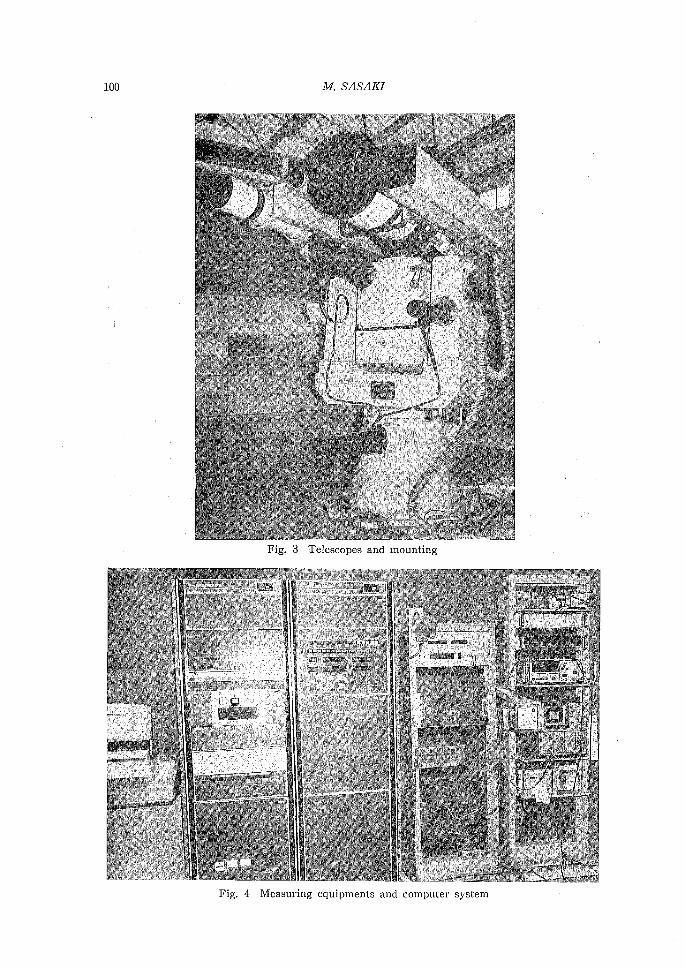
Fig. 3 T巴lescopesand mounting
Fig. 4 Measuring equipments and comput巴rsystem

AN EXPERIMENTAL SYSTE』fFOR SATELLITE LASER RANGING 101
This system has two controllers. One is the controller for laser transmission
and range measurement. Another is for mounting control.
The former controls laser transmission, operation of measuring equipments, pho-
tographing of images on the oscilloscope screen, shutter rotation, I/O cycles bet-
ween CPU and measuring巴quipmentsand between CPU and mounting controller.
Firing intervals can b巴setby digital switches from 5 sec to 99 sec. Every I/O cycle
between CPU and mounting controller is selected from 0. 1 sec to 9. 9 sec by this co・
ntroller. Though the computer treats many data, manual control can be executed
without the computer if necessary. At that case time of laser fire and flight time
are printed out by two backぺlPprinters, respectively.
The latter controller with arithmetic circuits controls the mounting. Tracking
of satellite is perform巴din either of three modes; manual, programing and automa・
tic. In any case the mounting is driven by pulse moters and the pointing direction
of the telescopes are detected by encoders.
In manual mode, rough tracking are performed according to the set values on a
key board. Fine adjustment of the dr甘 ingspeed of the mounting axes is made ma・
nually with handswitches by sighting the satellite in the telescope field visually.
In programing mode, the computer provides tracking velocities to the controller
for pulse motor driving and reads out the integrated values of output pulses of en司
coders from the controller. If a deviation between the position of the actual satellite
and one of the pr巴dictionexists, the observer controls the direction of the telescope
visually with hand switches and commands the computer to correct the prediction
suitably. Then, tracking accuracy is superior to that of the manual mode.
In automatic mode, the telescope for tracking follows the satellite motion auto-
matically after capture of the satellite image. Main units of this ,mode are ; tele-
scope, image intensifier, TV camera and XY-analyzer. Tracking is executed in the
following way. If a satellite image deviates from a set point of the TV camera, the
XY司analyzerdetects it’s amount and generates voltage level corresponding to the di-
splacement. The output level from the analyzer is digitalized in A/D converter and
then added to the tracking speeds initially set in the arithmetic logic unit. Thus
the satellite image is kept stationary at the same position on the screen.
Two contr叫lersare fully available in case of using computer. NOVA-01 (Nip-
pon Mini”Computer) with core-memory of 24kilowords is adopted as computer with
peripherals of a magnetic disk of 24Megawords, a paper tape reader and a tele-type圃
writer. Measuring equipments and two controllers are link巴dto CPU through inter司
faces of six I/O modules and three multiplexer modules. In addition to the on”line
system control, CPU calculates and revises the prediction. The CPU also processes
the obtained data and stores them into the disk.
(6) Self check and safety system
The system has following check-up functions. The system controller has laser
transmitting and receiving simulation circuits which check measuring instruments
and 1/0 cycles of the computer. According to the switched values of delay time of

102 M. SASAK1
laser transmission and flight time these circuits generate simulation puls巴s. The co-
mputing counter has self-check mode. The 1/0 data of the computer are check巴d
by a software ch巴ckingprogram.
The system contains some sources of danger. They are high output power laser
which seriously harms eyes when it goes in and high voltage power supply of big
capacity. In order to avoide accidents safety switches are prepared at critical
points and they stop the system when someone op巴nsthese switches. In addition
laser firings are warned by buzzar sounds.
3. Test日 ofeach part of the system
Some performance tests of each part and examinations of their specifications
have been made.
(1) Laser
Th巴 patternof the transmitt巴dlaser beam was examined by exposuring on pho”
tographic printing paper and a circular image of almost uniform intensity has b巴en
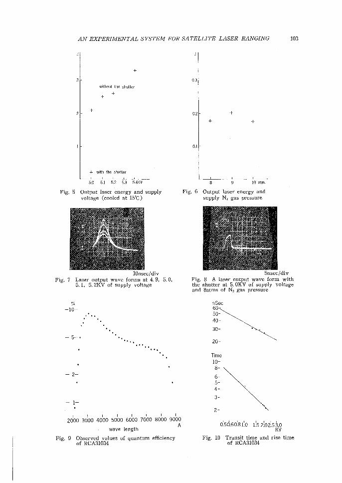
obtained. Output energy was measured by using caloriemeter. Examples of the re-
sult are shown in Fig. 5. Fig. 6 shows relation b巴tweenoutput power and pressure
of nitrogen gas. The output energy attains to 3. 3 Joules in maximum and half
height width is 21nsec. They correspond to 160 Mw. When the shutter is equipped
those values becomes 0. 2 Joules, 6nsec and 34Mw. The wav巴 formsare shown in
Fig. 7 and 8, respectively.
(2) PMT
Quantum efficiency has been measured by use of spectrometer. As can be seen
in Fig. 9, the e伍ciencyis 4% at tne wave length 6900A. Transit time and rise time,
both of which a妊ectthe accuracy of distance measur官 nentdirectly, have been mea-
sured with pulse generator, high speed photodiode and TK 7904. Obtained data are
shown in Fig. 10.
(3) Miscellaneous
Fair results have been obtained in the various tests about the performance of
the control system and relating parts. For instance, many electric circuit t巴sts,
delay time measurements of simulation signals, laser and telescope diverg巴ncetest,
adjusting of field center of telescopes and so on. As for the tracking, the automatic
mode was examined for stars up to 6th magnitude. Some sup巴riorresults were re-
port巴dby a member of GSI.
(4) Ranging tests to a ground target
A ground target was set at 18511 meters apart from the system and l百 1ging
tests were performed. In a case, the measm百 lmean distance was 18527. 8±0. lm
by 34 emissions without the electro-optical shutter・andthe standard devi日tionto
one puls巴 was0. 6m. The main part of difference in distance will be explain巴dby
the delays of amplifiers (2. Om), PMT (10. 2m), attenuators (1. 2111) and cables.
The remainder is interpreted as relative triggerlevel-difference between transmitt巴d
signals and received signals. The further investigation for the difference is con-
AN EXPERIMENTAL SYSTEM FOR SATELLITE LASER RANGING 103
十
3
w1lhoul the shutter
十+
十
+ with the shutter
5.0 5.1 5.2 5.3 5.4KV
Fig. 5 Output laser energy and supply voltage (cooled at 15℃)
lOnsec/div Fig. 7 Laser output wave forms at 4. 9, 5. 0,
5. 1, 5. 2KV of supply voltage
'" " -10一
- 5-・
. . .
・ .・・・-.
-2-
-1一
2000 30100 4000 5000 6000 7000 8000 9000 A
wave length
Fig. 9 Observ巴dvalues of quantum efficiency of RCA31034
0.3
0.2 +
十 +
0.1
8 9 10 atm.
Fig. 6 Output laser energy and supply N2 gas pressur・巴
5nsec/div Fig. 8 A las巴routput wave form with the shutter at 5. OKV of supply voltage and Satms of N2 gas pressure
PU
Aじ
て
一
一
一
ponunununu
nrDkdA邑
qu
20-
i~ \
o'.50.Go'.s1'.o 1'.5 2'.021.53.o KV
Fig. 10 Transit time and rise time of RCA31034

104 』d「.SASAKJ
tinued.
4. Concluding remarks
Although it is difficult to assert that the system has been completed, the funcla-
mental problems ar巴 consideredto have b巴ensolved through th巴 manufacturingwo-
rks and some tests described above.
(i) The electro句opticalshutter e妊ectssatisfactorily to sharpen the emitting light,
though output pow巴rhas not been as large as was aimed at first. However, this
situation is considerd to be improved by inserting a power amplifier of laser light
between th巴 shutterand the tr羽 ismittingtelescope. It is desired that the actual
type for field works is equipped with an amplifier.
(ii) Specifications of present system are summarized in Table 1, where values fol-
lowed by an asterisk (り arethose taken from the original d巴signor from the data
catalogs of each equipment or estimated values. According to these data and some
assumed values relation between number of receiving photoelectrons and range are
estimated using the formula;
N=(E/hν)GTA日GsAn(T2/戸)αf:J1刀
where E: laser energy (3. 3 Joules without the shutter and 0. 2 Joule with the shut-
ter), hν :energy per photon (at wave lengthえニ0.69x10 6m), G'r : transmitter gain
(full widthθ=1. 0×10-3rad), As : satellite effective ar巴a(0. 09m2), Gs : satellite mir~
ror gain (0=1. 0×1Q-4rad), An : receiver area (diameter dニ 0.4m), T : atmospheric
transmission factor (0. 5), p : range to satellite,α:transmitting efficiency (0. 5),戸:
mirror e缶ciency(0. 5), r : receiver efficiency (0. 2) andド quantumefficiency (0. 04).
Estimated values are following. The range which can be measured with only
one photoelectron at 3. 3 Joul巴S of laser en巴rgywithout the shutter is 1.0×l04km and
and the similar range is 5. 0×l03km at 0. 2 Joule with th巴 shutter. But with only
one photoelectron the received wave form can’t b巴 analyzed. If fifty photo巴lectrons
can be obtain巴dthe analysis can be fully performed. The ranges with fifty photo司
electrons are 3. 8×10³km without the shutter and 1. 9 x l03km with one.
(iii) Experiments of the automatic tracking system has given satisfactory r巴sults.
Although trackings in programing modes have not b巴entried, they seem to concern
only softwares involving proficiency of observers because the tracking mechanisms
have b巴巴ndesign巴dto hav巴 anaccuracy of 士0!5and their satisfactory performanc巴s
have been certificated in the automatic mode.
(iv) This system had been intended to be a portable typ巴 butit could not be real-
ized because of some restrictions. On the stage of field works the portability is in-
disp巴nsable Since th巴 presentsystem can be operated without computer as men-
tioned in section 2-(5), in the case of the next system for practical use it is desi-
red that the system will be operated without computer as the tracking ar巴 easily
performed owing to th巴 brightnessof th巴 satellite. But precise tracking is so impo司
rtant because light divergenc巴 affectsthe intensity of returning light as square of
its amount. If the divergence can be a half it makes possible to lessen the aperture

AN EXPERIMENTAL SYSTEM FOR SATELLITE LASER RANGING 105
of the receiving telescope by a half or output power of transmitting light by a qua-
ter. Considering thes巴 mattersminimization of the system has to be performed wi-
thin limits of high reliability and high accuracy. Corresponding to the minimiza-
tion of the laser oscillator, telescopes and mounting, it is required to make those
equipments of electric power supply and cooling tower for laser smaller.
Table 1 Specifications of the Laser Ranging System
Laser energy
half-power full width (min.)
power (max.)
light div巴rgenceof ruby rod
frequency of emission
shutter typ巴
cooling type
Transmitt巴robjectiveゆ
transmitting divergenc巴
Receiver objectiv巴件
focal length
Range (max., with on巴 photoelectron)
range (max., with 50 photo巴lectrons)
rangmg accuracy
Tracking system
tracking modes
driv巴
direction reading
auto-tracking
tracking accuracy
PMT transit tim (min.)
rise time (min.)
Oscilloscope resolution
rise time
Counter resolution
Amplifier rise tim巴
CPU memory
Disk memory
3. 3 Joule
21 nsec
160 Mw
5 mrad*
0.2 Hz
Pockels c巴11with nitrogen gas
cooled water
76 mm
1~3 mrad* (varねble)
400 mm
with the shutter O. 2 Joule
6 nsec
34 Mw
1200 mm (6600111111 effective)
10000 km 5000 km
3800 km 1900 km
1 mキ 0.5 mキ
3 ax巴stype
manual, programming and automatic
3 pulse motors
3 encoders
imag巴 intensifier,TV camera and XY-analyzer
土1 mrad*
26 nsec
2.1 nsec
O. 5 nsec/div'
0.8 nsec本
0.1 nsec本
O. <1 nsec*
24 kwords
2. 4 Mword(real tim巴 diskoperating system)

106 M. SASAKI
This research is a joint work of the Hydrographic Department and the Geogra幽
phical Survey Institute. The sta妊sare
JHD: T. Mori, Y. Ganeko E. Nishimura and M. Sasaki (author)
GSI : T. Hokugo, Y. Miyazaki, Y. Baba and H. Kaneko,
The author is deeply indebted to Dr. A. Tsuchiya and Mr. K. Tomita of the
Tokyo Astronomical Obs巴rvatoryfor their precious advices and discussions.
References
Kozai, Y., Tsuchiya, A., Tomita, K., Kanda, T., Sato, H., Kobayashi, N. and Torii, Y. 1973,
Tokyo Astronomical Bulletin, 223, 2597.
Ono, F. 1966, R巴portof Hydrographic Resear℃hes, No. 1, 63.
Ono, F. 1968, ibid. No. 4, 59.
Tomita, K. and Kanda, T. 1973, Tokyo Astronomical Observatory Report, 16, No. 3, 657.
Yamazaki, A. 1971. Report of Hydrographic Researches, No. 7, 1.
Yamazaki, A., Mori, T. and Ganeko, Y. 1972, Researches in Hydrograρhy and Oceanogrゆhy,in
co111111e111oration of the centenary of the Hydrograρhie Deρartment of faρan, Ed. D, Shoji,
Tokyo, p. 251.