recent developments in co2 removal membrane...
TRANSCRIPT

J J J
1
© 1999 UOP LLC, Des Plaines, Illinois. All rights reserved. Printed in USA.
J J J J J J J J J J
Recent Developmentsin CO2 Removal Membrane
Technology
David DortmundtKishore Doshi
Abstract
Membrane systems have become a tried and accepted natural gas treating technology with dis-tinct advantages in a variety of processing applications. From the earliest units producing below10 MM SCFD treated gas, systems are now in place to produce upward of 250 MM SCFD.Plans for plants producing 500 MM SCFD and higher are in the works. Although most unitshave been installed onshore, some offshore facilities do exist, and many more are planned.These systems, as well as those in the Middle East and elsewhere, exploit the reliability andminimum manpower requirements of membranes.
Some early installations highlighted the need for suitable preprocessing prior to membrane treat-ment. This need has led to the development of a robust and comprehensive pretreatment schemethat ensures extended membrane life. This pretreatment, in combination with the continuingdevelopment of advanced membranes, has even further enhanced the reliability and performanceof membrane technology and made it the CO2 removal technology of choice in a variety of pro-cessing conditions.
This paper describes operating experiences and design philosophy for larger membrane-basedCO2 removal plants.

Introduction
Membranes have become an established technology for carbon dioxide (CO2) removal sincetheir first use in this application in 1981. Initial acceptance was slow and limited to smallerstreams, mostly because of the economic risks involved in treating larger streams, but alsobecause many process design parameters were largely unknown. A further factor was the generaldownturn in the oil and gas industry in the 1980s.
The multiple benefits of membrane technology promised by early innovators have since beenproven in a wide variety of installations in many locations around the world, and vendors of traditional CO2 removal technologies have been quick to acquire or develop membrane-basedprocesses to supplement their older processing routes. Such companies have been able toachieve the best of both worlds: hybrid systems. In some cases, the most economical approach isto combine membranes with existing technologies or use membranes to debottleneck existingsolvent-based plants.
Membrane companies have had to allocate significant portions of their revenues to research anddesign efforts. This investment has been necessary to fully understand the dynamics of mem-brane system operation over time and also to further enhance membrane performance. The latterhas been achieved by modifying existing membrane materials and investigating alternativemembrane materials. Of equal importance have been improvements in membrane element con-figuration, pretreatment design, and optimization of the system’s mechanical design.
This paper summarizes the principles involved in CO2 removal by membranes, design consider-ations, UOP’s experiences in larger plants, and recent innovations by UOP’s Gas Processinggroup, both in membrane and membrane pretreatment design.
The Need for CO2 Removal
Carbon dioxide, which falls into the category of acid gases (as does hydrogen sulfide, for example) iscommonly found in natural gas streams at levels as high as 80%. In combination with water, it ishighly corrosive and rapidly destroys pipelines and equipment unless it is partially removed or exoticand expensive construction materials are used. Carbon dioxide also reduces the heating value of anatural gas stream and wastes pipeline capacity. In LNG plants, CO2 must be removed to preventfreezing in the low-temperature chillers.
A wide variety of acid gas removal technologies are available. They include absorption process-es, such as the BenfieldTM process (hot potassium carbonate solutions) and Amine Guard-FSTM
process (formulated solvents); cryogenic processes; adsorption processes, such as pressureswing adsorption (PSA), thermal swing adsorption (TSA) and iron sponge; and membranes.
Each process has its own advantages and disadvantages, but membranes increasingly are beingselected for newer projects, especially for applications that have large flows, have high CO2
contents, or are in remote locations. The reasons for this choice are described later in the paper.
J J J
2

J J J
3
Membranes have been widely used in two main CO2 removal applications:
J Natural gas sweetening
J Enhanced oil recovery (EOR), where CO2 is removed from an associated natural gasstream and reinjected into the oil well to enhance oil recovery
Other applications also exist, for example landfill gas purification, but these applications are far fewerin number.
Membranes
Membranes are thin semipermeable barriers that selectively separate some compounds from others. This definition is necessarily broad because of the large variety of membrane materialsseparating an equally vast number of compounds in all phases. Applications include:
J Ceramic membranes for gas purification in the semiconductor industry
J Palladium-based metallic membranes for hydrogen extraction
J Silicon rubber membranes for organic vapor recovery from air
J Polyvinyl alcohol-based membranes for ethanol dehydration
Membrane Materials for CO2 Removal
Currently, the only commercially viable membranes used for CO2 removal are polymer based,for example, cellulose acetate, polyimides, polyamides, polysulfone, polycarbonates, and poly-etherimide. The most widely used and tested material is cellulose acetate as used in UOP’smembrane systems. Polyimide has some potential in certain CO2 removal applications, but ithas not received sufficient testing to be used in large applications.
The properties of polyimides and other polymers can be modified to enhance performance. Forexample, polyimide membranes were initially used for hydrogen recovery but were then modi-fied for CO2 removal. Cellulose acetate membranes were initially developed for reverse osmosisbut are now the most rugged CO2 removal membrane available.
Membrane Permeation
The membranes used for CO2 removal do not operate as filters, where small molecules are sepa-rated from larger ones through a medium with pores. Instead, they operate on the principle ofsolution-diffusion through a nonporous membrane. The CO2 first dissolves into the membraneand then diffuses through it. Because the membrane does not have pores, it does not separate onthe basis of molecular size. Rather, it separates based on how well different compounds dissolveinto the membrane and then diffuse through it.

Because carbon dioxide, hydrogen, helium, hydrogen sulfide, and water vapor, for example, permeate quickly, they are called “fast” gases. Carbon monoxide, nitrogen, methane, ethane andother hydrocarbons permeate less quickly and so are called “slow” gases. The membranes allowselective removal of fast gases from slow gases. For example, as CO2 is removed from a naturalgas stream, water and H2S are removed at the same time; but methane, ethane, and higherhydrocarbons are removed at a much lower rate.
Fick’s law, shown below, is widely used to approximate the solution-diffusion process:
is the membrane flux of CO2, that is, the molar flow of CO2 through the membrane per unitarea of membrane.
is the solubility of CO2 in the membrane.
is the diffusion coefficient of CO2 through the membrane.
is the partial pressure difference of CO2 between the feed (high pressure) and permeate(low pressure) side of the membrane.
is the membrane thickness.
To simplify matters further, the solubility and diffusion coefficients are usually combined into anew variable called permeability (P). Fick’s law can therefore be split into two portions: a mem-brane-dependent portion (P/ ) and a process-dependent portion (∆p). To achieve a high flux, thecorrect membrane material and the correct processing conditions are needed. P/ is not a constant; it is sensitive to a variety of operating conditions such as temperature and pressure.
The Fick’s law equation can be equally written for methane or any other component in thestream. This set of equations leads to the definition of a second important variable called selectivity (α). Selectivity is the ratio of the permeabilities of CO2 to other components in thestream and is a measure of how much better the membrane permeates CO2 compared to thecompound in question. For example, most CO2 membranes provide a CO2-to-methane selectivityanywhere between 5 and 30, meaning that CO2 permeates the membrane 5 to 30 times fasterthan methane.
Both permeability and selectivity are important considerations when selecting a membrane. Thehigher the permeability, the less membrane area is required for a given separation and thereforethe lower the system cost. The higher the selectivity, the lower the losses of hydrocarbons asCO2 is removed and therefore the higher the volume of salable product.
J J J
4

Unfortunately, high CO2 permeability does not correspond to high selectivity, though achievingthis combination is a constant goal for membrane scientists. Instead, they have to settle for ahighly selective or permeable membrane or somewhere in-between on both parameters. Theusual choice is to use a highly selective material then make it as thin as possible to increase thepermeability. However, this reduced thickness makes the membrane extremely fragile and there-fore unusable. For many years, membrane systems were not a viable process because the mem-brane thickness required to provide the necessary mechanical strength was so high that thepermeability was minimal. An ingenious solution to this problem allowed membranes to breakthis limitation.
Membrane Structure
The solution was to produce a membrane consisting of an extremely thin nonporous layermounted on a much thicker and highly porous layer of the same material. This membrane struc-ture is referred to as asymmetric, as opposed to an homogenous structure, where membraneporosity is more-or-less uniform throughout. An example of an asymmetric membrane is shownin Figure 1.
J J J
5
Figure 1
Asymmetric Membrane Structure
Nonporous Layer
Porous Layer
Nonporous Layer
Porous Layer
(Reproduced with permission from Rautenbach2)

The nonporous layer meets the requirements of the ideal membrane, that is, it is highly selectiveand also thin. The porous layer provides mechanical support and allows the free flow of com-pounds that permeate through the nonporous layer.
Although asymmetric membranes are a vast improvement on homogenous membranes, they dohave one drawback. Because they are composed of only one material, they are costly to makeout of exotic, highly customized polymers, which often can be produced only in small amounts.This difficulty is overcome by producing a composite membrane, which consists of a thin selec-tive layer made of one polymer mounted on an asymmetric membrane, which is composed ofanother polymer. This composite structure allows membrane manufacturers to use readily avail-able materials for the asymmetric portion of the membrane and specially developed polymers,which are highly optimized for the required separation, for the selective layer. An example ofthis structure is shown in Figure 2.
Composite structures are being used in most of the newer advanced CO2 removal membranesbecause the properties of the selective layer can be adjusted readily without increasing membranecost too significantly.
J J J
6
Figure 2
Composite Membrane Structure
SelectiveLayer
AsymmetricMembrane
(Reproduced with permission from Rautenbach2)

J J J
7
Figure 3
Spiral Wound Membrane Element
UOP 2320P-28
Membrane Elements
Gas separation membranes are manufactured in one of two forms: flat sheet or hollow fiber. Theflat sheets are typically combined into a spiral-wound element, and the hollow fibers are com-bined into a bundle similar to a shell and tube heat exchanger. Figures 3 and 4 illustrate theseelement types.
In the spiral-wound arrangement, two flat sheets of membrane with a permeate spacer inbetween are glued along three of their sides to form an envelope (or leaf, as it is called in themembrane industry) that is open at one end. Many of these envelopes are separated by feedspacers and wrapped around a permeate tube with their open ends facing the permeate tube.
Feed gas enters along the side of the membrane and passes through the feed spacers separatingthe envelopes. As the gas travels between the envelopes, CO2, H2S, and other highly permeablecompounds permeate into the envelope. These permeated components have only one outlet: theymust travel within the envelope to the permeate tube. The driving force for transport is the low-permeate and high-feed pressures. The permeate gas enters the permeate tube through holesdrilled in the tube. From there, it travels down the tube to join the permeate from other tubes.Any gas on the feed side that does not get a chance to permeate leaves through the side of theelement opposite the feed position.
Feed Spacer
Membrane
Permeate Spacer
Membrane
Feed Spacer
Low CO2Product
Low CO2Product
PermeateCO2-Rich
Gas
Feed
High CO2 NG

Possible optimizations for spiral-wound elements include the number of envelopes and elementdiameter. The permeate gas has to travel the length of each envelope, so having many shorterenvelopes makes more sense than a few longer ones because pressure drop is greatly reduced inthe former case. Larger-bundle diameters allow better packing densities but increase the elementtube size and therefore cost. They also increase the element weight, which makes the elementsmore difficult to handle during installation and replacement.
In hollow-fiber elements, very fine hollow fibers are wrapped around a central tube in a highlydense pattern. In this wrapping pattern, both open ends of the fiber end up at a permeate pot onone side of the element. Feed gas flows over and between the fibers, and some components per-meate into them. The permeated gas then travels within the fibers until it reaches the permeatepot, where it mixes with the permeates from other fibers. The total permeate exits the elementthrough a permeate pipe.
The gas that does not permeate eventually reaches the element’s center tube, which is perforatedin a way similar to that of the spiral-wound permeate tube. In this case, however, the centraltube is for residual collection, not permeate collection.
J J J
8
Figure 4
Hollow-Fiber Membrane Element
UOP 2320P-29
FeedHigh CO2 NGLow CO2
Product
PermeateCO2 Rich Gas
Membrane

Many optimizations are possible for hollow-fiber elements. They include adjusting fiber diame-ters: finer fibers give higher packing density but larger fibers have lower permeate pressuredrops and so use the pressure driving force more efficiently. Another optimization is the sleevedesign, which forces the feed to flow countercurrent to the permeate instead of the more-usualand less-efficient cocurrent flow pattern.
Each element type has its own advantages. Spiral-wound elements can handle higher pressure,are more resistant to fouling, and have a long history of service in natural gas sweetening.Hollow-fiber elements have a higher packing density, and so hollow fiber-based plants are typi-cally smaller than spiral wound-based plants. Those vendors that supply both types of elementscan provide objective reasons for choosing one type over the other.
Membrane Modules and Skids
Once the membranes have been manufactured into elements, they are joined together and insert-ed into a tube (Figure 5).
Multiple tubes are then mounted on skids in either a horizontal or vertical orientation, dependingon the membrane company. A skid with horizontal tubes is shown in Figure 6.
J J J
9
Figure 5
Membrane Module with Elements
UOP 3128-5
Residual
Feed
Permeate
Permeate Tube Union
Membrane Housing
Membrane Element
Inlet Seal(U-Cup)

Advanced Membrane Development
UOP has an ongoing effort to produce novel and enhanced polymers for membranes. Thesecompounds are initially tested in the laboratory followed by pilot testing on slipstreams of actualgas plants and then installed in full-scale plants. Extensive testing on a wide variety of gasstreams is imperative to ensuring the long-term, stable, and efficient operation of membrane systems. New membranes cannot be considered truly reliable until this testing is done becausedifferent membranes are affected differently by different compounds and operating conditions.For example, because polyimide membranes are much more sensitive to heavy hydrocarbonsthan cellulose acetate, more-rigorous pretreatment is required.
UOP is developing both advanced spiral-wound and hollow-fiber membranes. UOP’s advancedpolyimide-based hollow-fiber membranes have already been used in a major plant and have alsobeen installed on slipstreams in other plants already using UOP’s current membranes. Theseadvanced membranes have significantly higher selectivities than current membranes, but havelower permeabilities. The permeability can be increased by adjusting operating conditions, suchas temperature.
The advanced spiral-wound membranes are not as commercially developed as the hollow-fiberproduct but show even more promise. These spiral-wound membranes are based on a proprietary
J J J
10
Figure 6
Membrane Skid

J J J
11
polymer that provides significantly higher selectivities at similar permeabilities to current prod-ucts. These membranes are currently completing extended pilot-plant trials.
When advanced membranes are retrofitted into existing membrane tubes, they reduce hydrocarbonlosses, reduce recycle compressor power consumption, and increase the plant’s production capacity.
Design Considerations
Many process parameters can be adjusted to optimize performance depending on the customerand application needs. Optimization is most critical for larger systems where small improve-ments can bring large rewards. Some typical requirements are:
J Low cost
J High reliability
J High on-stream time
J Easy operation
J High hydrocarbon recovery
J Low maintenance
J Low energy consumption
J Low weight and space requirement
Many of these requirements work against one another: for example, a high-recovery system usu-ally requires a compressor, which increases maintenance costs. The design engineer must there-fore balance the requirements against one another to achieve an overall optimum system. Theprocess variables affecting the design are described in the rest of this section.
Flow Scheme
The simplest membrane processing scheme is a one-stage flow scheme (Figure 7). A feed gas isseparated into a permeate stream rich in CO2 and a hydrocarbon-rich residual stream.
In high CO2 removal applications, a significant amount of hydrocarbons permeate the membraneand are lost. Multistage systems attempt to recover a portion of these hydrocarbons. The two-step design shown in Figure 8 allows only a portion of the first-stage permeate to be lost. Therest is recycled to the feed of the first stage.
The portion of first-stage permeate that is lost is usually taken from the first membrane modules,where feed CO2, hence permeate CO2, is highest and hydrocarbons are lowest. The permeatethat is recycled is at low pressure and must be repressurized before it can be combined with thefeed gas.

J J J
12
Figure 9
Two-Stage Flow Scheme
UOP 3128-9
Permeate
Feed
Residue
Figure 7
One-Stage Flow Scheme
UOP 3128-7
Residue(CO2 Reduced)
MembraneUnitFeed
Permeate(CO2 Enriched)
Figure 8
Two-Step Flow Scheme
UOP 3120-8
Residue
Feed
Permeate

J J J
13
Two-stage designs process the first-stage permeate in a second membrane stage, as shown inFigure 9.
The permeate from the second stage, which has typically twice the CO2 content as the first-stagepermeate, is vented. The residue is either recycled and combined with the feed gas. A compres-sor is required to repressurize the first-stage permeate before it is processed in the second stage.Two-stage designs provide higher hydrocarbon recoveries than two-step or one-stage designs butrequire more compressor power (because more gas must be compressed to be treated).
Other flow schemes are also possible though rarely used. One exception is the two-stage withpremembrane flow scheme, where a single-stage system provides bulk CO2 removal, followedby a two-stage system for final CO2 removal. This scheme uses a much smaller recycle com-pressor than that required by a standard two-stage system, although hydrocarbon losses are high-er because of the single-stage portion of the system.
When deciding whether to use a single-stage or multistage system, many factors must be consid-ered. An economic analysis must be completed to ensure that the cost of installing and operatinga recycle compressor does not exceed the savings in hydrocarbon recovery. Figure 10 illustratesthis issue.
The percentage hydrocarbon recovery is plotted versus percentage CO2 removal for one- andtwo-stage systems at certain process conditions. The percentage hydrocarbon recovery isdefined as the percentage of hydrocarbons recovered to the sales gas versus the hydrocarbons inthe feed gas.
Figure 10
Effect of Number of Stages
UOP 3128-10
0 100
Hyd
ocar
bon
Rec
over
y, %
75
100
% CO2 Removal
90
85
80
20 40 60 80
Two-Stage95
One-Stage

The hydrocarbon recovery of a two-stage system is significantly better than that for a single-stage system. However, when deciding whether to use a single or multistage approach, thedesigner must also consider the impact of the recycle compressor. This impact includes the addi-tional hydrocarbons used as fuel, which increases the overall hydrocarbon losses, as well as thesignificant capital cost of compressors and the difficulty of maintaining them in remote loca-tions. For moderate CO2 removal applications, that is, below approximately 50%, single-stagemembrane systems usually provide better economic returns than do multistage systems.
Flow Rate
Because membrane systems are modular, an increase in flow rate causes a directly proportionalincrease in membrane area requirement, for a given separation. Hydrocarbon losses, that is, theflow rate of hydrocarbons lost to vent, also increases proportionally, but the percentage hydro-carbon losses (hydrocarbon losses ÷ feed hydrocarbons) stay constant.
Operating Temperature
An increase in feed temperature increases membrane permeability and decreases selectivity. Themembrane area requirement is therefore decreased, but hydrocarbon losses and the recycle com-pressor power for multistage systems are increased, as shown in Figure 11.
Feed Pressure
An increase in feed pressure decreases both membrane permeability and selectivity. However,the increased pressure creates a greater driving force across the membrane. A net increase in per-
J J J
14
Figure 11
Effect of Operating Temperature
UOP 3128-11
70 170
Rel
ativ
e A
rea
or L
osse
s
0.5
1.5
Operating Temperature, °F
1.1
0.9
0.7
90 110 130 150
HydrocarbonLosses
1.3
MembraneArea

meation through the membrane results and the membrane area requirement therefore drops.Compressor power increases slightly, and hydrocarbon losses decrease slightly (Figure 12).
Because the membrane area requirement is so affected by pressure, while other variables arenot, designers attempt to use the maximum operating pressure possible to achieve a cheaper andsmaller system. A limiting factor is the maximum pressure limit for the membrane elements andthe cost and weight of equipment at a higher-pressure rating.
Permeate Pressure
The effect of permeate pressure is the opposite of the effect of feed pressure. The lower the per-meate pressure, the higher the driving force and therefore the lower the membrane area require-ment. Unlike feed pressure, however, permeate pressure has a strong effect on hydrocarbon losses(Figure 13).
The pressure difference across the membrane is not the only consideration. Detailed analysisshows that an equally important factor in system design is the pressure ratio across the mem-brane. This ratio is strongly affected by the permeate pressure. For example, a feed pressure of90 bar and a permeate pressure of 3 bar produce a pressure ratio of 30. Decreasing the permeatepressure to 1 bar increases the pressure ratio to 90 and has a dramatic effect on system perfor-mance. For this reason, membrane design engineers try to achieve the lowest-possible permeatepressure. This need is an important consideration in deciding how to further process the perme-ate stream. For example, if it must be flared, then flare design must be optimized for low pres-sure drop. If the permeate gas is to be compressed, for example, to feed it to a second membrane
J J J
15
Figure 12
Effect of Feed Pressure
UOP 3128-12
400 1600
Rel
ativ
e A
rea
or L
osse
s
0.0
2.0
Feed Pressure, psia
1.2
0.8
0.4
600 800 1000 1200
HydrocarbonLosses
1.6
MembraneArea
1400

stage or reinject it into a well, the increased compressor power and size at low permeate pres-sures must be balanced against the reduced membrane area requirements.
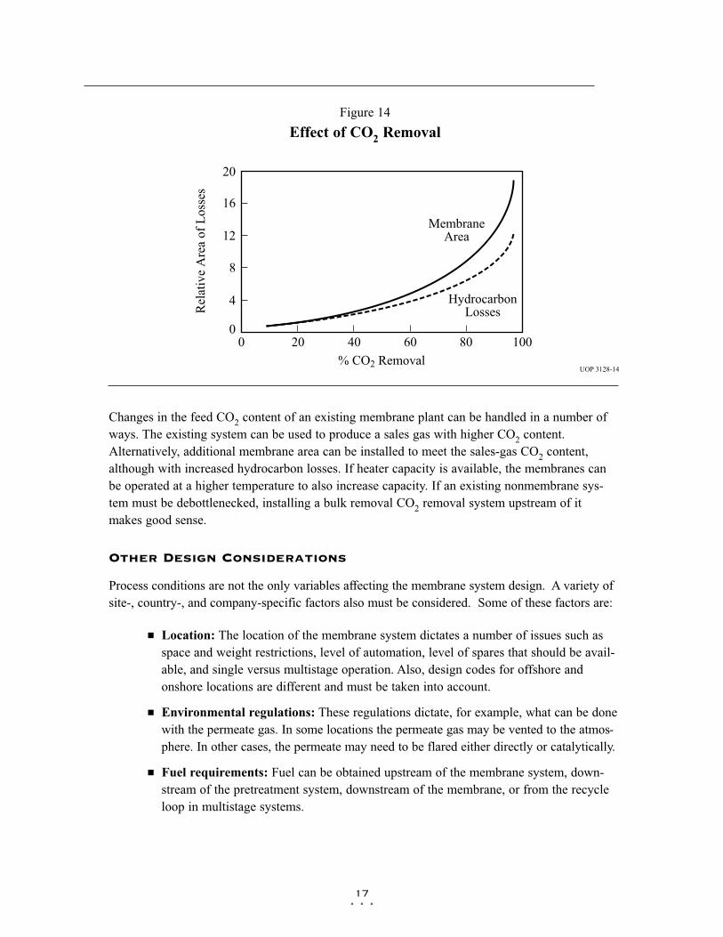
CO2 Removal
For a given sales-gas CO2 specification, an increase in feed CO2 increases membrane arearequirement as well as hydrocarbon losses (more CO2 must permeate, and so more hydrocarbonspermeate). This is shown in Figure 14.
The membrane area requirement is determined by the percentage of CO2 removal rather than thefeed or sales-gas CO2 specifications themselves. For example, a system for reducing a feed CO2
content from 10 to 5% is similar in size to one reducing a feed from 50 to 30% or one reducinga feed from 1 to 0.5% ñ all have a CO2 removal requirement of about 55%. This behavior is dif-ferent from the way in which traditional CO2 removal technologies operate. For these opera-tions, a reduction in CO2 from 3 to 0.1% does not require a much larger system than thatrequired for a reduction from 3 to 1%. For a membrane system, the large difference in CO2
removal (97 versus 70%) means that the system for 0.1% sales gas is about three times the sizeof the 1% system.
Traditional solvent- or adsorbent-based CO2 removal technologies have the opposite limitation,that is, their size is driven by the absolute amount of CO2 that must be removed. So a systemfor CO2 removal from 50 to 30% is substantially larger than one reducing CO2 from 1.0 to0.5%. For this reason, using membranes for bulk CO2 removal and traditional technologies formeeting low CO2 specifications makes a lot of sense. Depending on the application, either oneor both of the technologies could be used.
J J J
16
Figure 13
Effect of Permeate Pressure
UOP 3128-13
0 160
Rel
ativ
e A
rea
or L
osse
s
0.6
3.0
Permeate Pressure, psia
2.2
1.8
1.0
40 80 120
HydrocarbonLosses
2.6 MembraneArea
1.4
J J J
17
Changes in the feed CO2 content of an existing membrane plant can be handled in a number ofways. The existing system can be used to produce a sales gas with higher CO2 content.Alternatively, additional membrane area can be installed to meet the sales-gas CO2 content,although with increased hydrocarbon losses. If heater capacity is available, the membranes canbe operated at a higher temperature to also increase capacity. If an existing nonmembrane sys-tem must be debottlenecked, installing a bulk removal CO2 removal system upstream of itmakes good sense.
Other Design Considerations
Process conditions are not the only variables affecting the membrane system design. A variety ofsite-, country-, and company-specific factors also must be considered. Some of these factors are:
J Location: The location of the membrane system dictates a number of issues such asspace and weight restrictions, level of automation, level of spares that should be avail-able, and single versus multistage operation. Also, design codes for offshore andonshore locations are different and must be taken into account.
J Environmental regulations: These regulations dictate, for example, what can be donewith the permeate gas. In some locations the permeate gas may be vented to the atmos-phere. In other cases, the permeate may need to be flared either directly or catalytically.
J Fuel requirements: Fuel can be obtained upstream of the membrane system, down-stream of the pretreatment system, downstream of the membrane, or from the recycleloop in multistage systems.
Figure 14
Effect of CO2 Removal
UOP 3128-14
0 100
Rel
ativ
e A
rea
of L
osse
s
0
20
% CO2 Removal
12
8
4
20 40 60 80
MembraneArea
16
HydrocarbonLosses

J Design standards: Design codes and standards vary from company to company.Some companies may require duplex lines, where others allow carbon steel. Somemay specify maximum pipe velocities of 0.5 psi/100 ft, while others may allow up to1.5. Even supposedly simple issues such as painting specifications can vary greatlyfrom company to company and can add significant unexpected cost. All such itemsmust be predetermined during the bidding stage to prevent costly modifications later.
Membrane Pretreatment
Proper pretreatment design is critical to the performance of all membrane systems. Improperpretreatment generally leads to performance decline rather than complete nonperformance.
Substances commonly found in natural gas streams that will lower the performance of CO2
removal membranes include:
J Liquids: Liquids cause swelling of the membranes and destruction of membraneintegrity.
J Heavy hydrocarbons, approximately > C15: Significant levels of these compoundsslowly coat the membrane surface, thus decreasing permeation rate.
J Particulate material: Particles can block the membrane flow area. The possibility ofblockage is much lower for spiral-wound membranes than for hollow-fiber mem-branes, which have a low flow area. However, a long-term particle flow into anymembrane could eventually block it.
J Certain corrosion inhibitors and well additives: Some corrosion inhibitors and welladditives are destructive to the membrane, but others are safe. Membrane vendorsshould be consulted before either of these groups of compounds is introduced.
The pretreatment system must remove these compounds and must also ensure that liquids willnot form within the membranes themselves.
Two effects may allow condensation within the membrane. First, the gas cools down, as a resultof the Joule-Thomson effect, as it passes through the membrane. Second, because CO2 and thelighter hydrocarbons permeate faster than the heavy hydrocarbons, the gas becomes heavier andtherefore its dew point increases through the membrane. Condensation is prevented by achievinga predetermined dewpoint before the membrane and then heating the gas to provide a sufficientmargin of superheat.
The pretreatment system must have a wide safety margin and be highly flexible to cope withunexpected circumstances. UOP’s experience has shown that the heavy hydrocarbon content of afeed gas can vary widely from initial pre-start-up estimates and also from month to month duringthe plant’s life. Large variations are seen even between different wells in the same area. A reliablepretreatment system must take this variation into account and must be able to protect the mem-branes against a wide range of contaminants.
J J J
18

Traditional Pretreatment
The traditional pretreatment scheme for membrane systems used in CO2 removal consists of thefollowing equipment (Figure 15):
J Coalescing filter for liquid and mist elimination
J Nonregenerable adsorbent guard bed for trace contaminant removal
J Particle filter for dust removal after the adsorbent bed
J Heater for providing sufficient superheat to the gas
Although this scheme is adequate for light, stable composition gases, it has the following limitations:
J The adsorbent bed is the only item removing heavy hydrocarbons. A sudden surge inheavy hydrocarbon content or heavier than initially estimated feed gas can saturatethe adsorbent bed within days and render it useless. Because these beds are typicallynonregenerable, they can become functional again only after the adsorbent has beenreplaced.
J Problems with the heater require that the whole membrane system be taken off-line,because the heater is the only item of equipment providing superheat.
Additions to Traditional Pretreatment
Various items of equipment are commonly added to the traditional pretreatment scheme toenhance its performance. The more common items are:
Chiller
A chiller may be included to reduce the dew point of the gas and also the heavy hydrocarboncontent. However, because chilling does not completely remove heavy hydrocarbons, an adsor-bent guard bed is still required. Furthermore, if deep chilling is necessary, then steps have to be
J J J
19
Figure 15
Traditional Membrane Pretreatment
UOP 3128-15
AdsorbentGuard Bed
CoalescingFilter
ParticleFilter Membrane
Feed
Heater
taken to prevent hydrates from forming either by dehydrating the gas upstream or addinghydrate formation inhibitors. If inhibitors are added, then they may need to be removed down-stream of the chiller because some inhibitors are damaging to the membrane.
Turboexpander
A turboexpander serves the same purpose as a chiller, but has the benefit of being a dry system.Turboexpanders are also smaller and lighter than a mechanical refrigeration system. A disadvan-tage is the net pressure loss, which must be taken up by the export compressor.
Glycol Unit
Glycol units are typically added upstream of a chiller to prevent hydrate formation or freeze-up.An adsorbent guard bed is still required for removing heavy hydrocarbons. This bed must beeven larger than it would normally be because it must also remove the glycol carried over fromthe absorber vessels.
Need for Enhanced Pretreatment
For many membrane systems, traditional pretreatment is adequate. However, UOP’s experiencewith a number of membrane systems has indicated the need for developing an enhanced pre-treatment system that can better handle higher or fluctuating heavy-hydrocarbon levels.
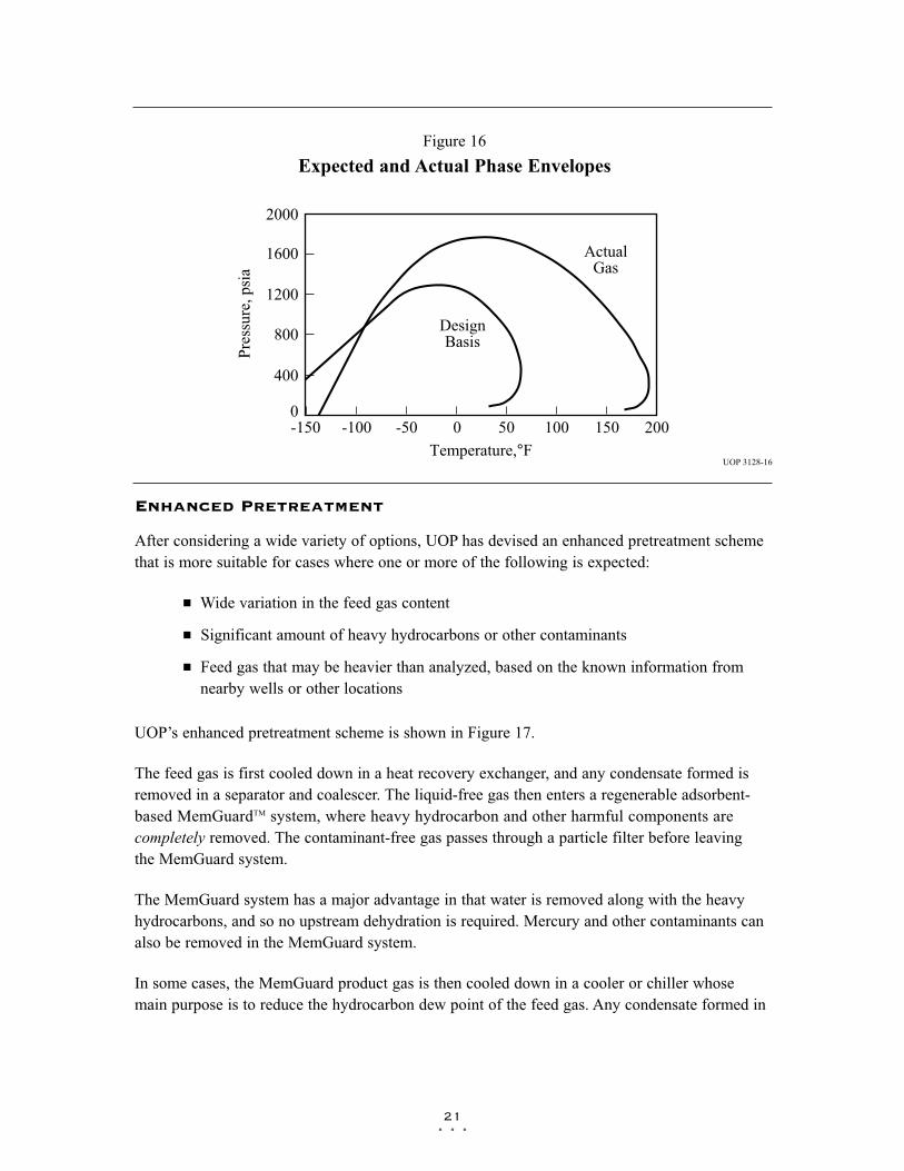
A large Separex™ membrane system was installed in 1995 to process what was expected to be alight gas. The client had supplied an extended gas analysis, which has been verified by externaltest agencies. Based on this analysis, the system was supplied with a traditional pretreatmentsystem, which consists of a coalescing filter, adsorbent guard bed, particle filter, and preheater.
A short while after the system was started up, however, deterioration in membrane performancewas observed, and UOP determined that the gas was significantly heavier than originally antici-pated. Figure 16 shows phase envelopes for the design and actual gas analysis.
The pretreatment system did not have sufficient flexibility to handle such a wide departure fromthe design conditions. First, the adsorbent bed was fully saturated within a short time, leading toperformance degradation. Second, the preheaters were not large enough to achieve feed temper-atures that were much higher than designed. A standard way to handle a gas that is heavier thanexpected is to operate the membranes at a higher temperature. This temperature increase increas-es the margin between the gas dew point and operating temperature and thus prevents condensa-tion in the membrane. In this case, the high temperature required could not be achieved by theinstalled heaters.
UOP proposed retrofitting with an enhanced pretreatment system. The client has this systemunder consideration but has not implemented it yet because well production is lower than expected.As a result, the heaters can raise the gas temperature enough to allow satisfactory performance.
J J J
20
J J J
21
Enhanced Pretreatment
After considering a wide variety of options, UOP has devised an enhanced pretreatment schemethat is more suitable for cases where one or more of the following is expected:
J Wide variation in the feed gas content
J Significant amount of heavy hydrocarbons or other contaminants
J Feed gas that may be heavier than analyzed, based on the known information fromnearby wells or other locations
UOP’s enhanced pretreatment scheme is shown in Figure 17.
The feed gas is first cooled down in a heat recovery exchanger, and any condensate formed isremoved in a separator and coalescer. The liquid-free gas then enters a regenerable adsorbent-based MemGuardTM system, where heavy hydrocarbon and other harmful components arecompletely removed. The contaminant-free gas passes through a particle filter before leavingthe MemGuard system.
The MemGuard system has a major advantage in that water is removed along with the heavyhydrocarbons, and so no upstream dehydration is required. Mercury and other contaminants canalso be removed in the MemGuard system.
In some cases, the MemGuard product gas is then cooled down in a cooler or chiller whosemain purpose is to reduce the hydrocarbon dew point of the feed gas. Any condensate formed in
Figure 16
Expected and Actual Phase Envelopes
UOP 3128-16
-150 200
Pres
sure
, psi
a
0
2000
Temperature,°F
1200
800
400
-100 -50 0 100
ActualGas
1600
DesignBasis
50 150

the chiller is removed in a separator and the separator-outlet gas is routed to the feed crossexchanger. Here the gas cools down the system-feed gas and also obtains necessary superheat.Further superheat and control of membrane feed temperature are provided by a preheater.
The key benefits of UOP’s enhanced pretreatment scheme are:
J Complete removal of heavy hydrocarbons: Unlike other pretreatment schemes, theabsolute cutoff of heavy hydrocarbons is possible.
J Regenerative system: Because the MemGuard unit is a regenerative system, it is bet-ter able to handle fluctuations in the heavy hydrocarbon content of the feed gas thanare traditional guard beds, which require frequent replacement of adsorbent material.
J Reliability: The MemGuard unit can be designed to operate satisfactorily even if oneof its vessels is taken off-line. Critical items in the pretreatment system are usuallyspared so they can be serviced or maintained without shutting the system down.
J Ability to cope with varying feed composition: The cycle time of the MemGuardunit can be adjusted to provide efficient treatment of a wide variety of feed composi-tions and heavy hydrocarbon contents.
J Efficiency: A single MemGuard unit is able to provide a number of functions, such asremoval of water, heavy hydrocarbons, and mercury, that would normally be providedby separate pieces of equipment. Heat recovery is implemented in the pretreatmentscheme as well as within the MemGuard system itself.
J J J
22
Figure 17
Enhanced Pretreatment Scheme
UOP 3128-17
Chiller orCooler
Not AlwaysRequiredFeed
HeatRecovery
Separatorand
Coalescer
Preheater
To Membranes
MemGuard™
System

J J J
23
UOP believes this enhanced pretreatment scheme is the most suitable one for the pretreatmentrequirements of large gas streams containing heavy hydrocarbons in the C10 to C35 range. Eventhough membrane systems cost only a fraction of the cost of a complete natural gas plant, theyare the heart of the system. If pretreatment is inadequate, the membrane deteriorates and produc-tion declines.
Extensive testing has proven the enhanced pretreatment concept, and it is currently operating intwo different customer locations. A third unit is currently under construction at an offshore loca-tion and is expected to start up in the fourth quarter of 1998.
Because the pretreatment system already includes many unit operations that are ordinarilyincluded in a gas plant, for example dehydration and dew-point control, membrane companiesmust be brought into a project early in its design. This collaboration prevents unnecessaryreworking of the flow scheme later on and may also allow significant cost savings on the part ofthe gas production company.
Advantages of Membrane Systems
Membrane systems have major advantages over more-traditional methods of CO2 removal:
J Lower capital cost: Membrane systems are skid mounted, except for the larger pre-treatment vessels, and so the scope, cost, and time taken for site preparation are mini-mal. Therefore, installation costs are significantly lower than alternative technologies,especially for remote areas. Furthermore, membrane units do not require the additionalfacilities, such as solvent storage and water treatment, needed by other processes.
J Lower operating costs: The only major operating cost for single-stage membranesystems is membrane replacement. This cost is significantly lower than the solventreplacement and energy costs associated with traditional technologies. The improve-ments in membrane and pretreatment design allow a longer useful membrane life,which further reduces operating costs. The energy costs of multistage systems withlarge recycle compressors are usually comparable to those for traditional technologies.
J Deferred capital investment: Often, contracted sales-gas flow rates increase overtime, as more wells are brought on-line. With traditional technologies, the systemdesign needs to take this later production into account immediately, and so the majori-ty of the equipment is installed before it is even needed. The modular nature of mem-brane systems means that only the membranes that are needed at start-up need beinstalled. The rest can be added, either into existing tubes or in new skids, only whenthey are required. Even on offshore platforms, where all space requirements must beaccounted for, space can be left for expansion skids rather than having to install themat the start of the project.
J Operational simplicity and high reliability: Because single-stage membrane systemshave no moving parts, they have almost no unscheduled downtime and are extremely
simple to operate. They can operate unattended for long periods, provided that exter-nal upsets, such as well shutdowns, do not occur. Items in the pretreatment system thatcould cause downtime, such as filter coalescers, are usually spared so that productioncan continue while the item is under maintenance. The addition of a recycle compres-sor adds some complexity to the system but still much less than with a solvent oradsorbent-based technology. Multistage systems can be operated at full capacity assingle-stage systems when the recycle compressor is down, although hydrocarbonlosses will increase. The start-up, operation, and shutdown of a complex multistagemembrane system can be automated so that all important functions are initiated from acontrol room with minimal staffing.
J Good weight and space efficiency: Skid construction can be optimized to the spaceavailable, and multiple elements can be inserted into tubes to increase packing density.This space efficiency is especially important for offshore environments, where deckarea is at a premium, and is the reason why so many new offshore developments havechosen to use membranes for acid gas removal. Figure 18 illustrates the space effi-ciency of membrane systems. The membrane unit in the lower left corner replaced allthe amine and glycol plant equipment shown in the rest of the picture.
J Adaptability: Because membrane area is dictated by the percentage of CO2 removalrather than absolute CO2 removal, small variations in feed CO2 content hardly changethe sales-gas CO2 specification. For example, a system designed for 10% down to 3%CO2 removal produces a 3.5% product from a 12% feed gas, and a 5% product from a15% feed gas. By adjusting process parameters such as operating temperature, thedesigner can further reduce the sales-gas CO2 content.
J High turndown: The modular nature of membrane systems means that low turndownratios, to 10% of the design capacity or lower, can be achieved. Turnup and turndownincrements can be set at whatever level is required during the design phase.
J Design efficiency: The membrane and pretreatment systems integrate a number ofoperations, such as dehydration, CO2 and H2S removal, dew-point control, and mer-cury removal. Traditional CO2 removal technologies require all of these operations asseparate processes and may also require additional dehydration because some tech-nologies saturate the product stream with water.
J Power generation: The permeate gas from membrane systems can be used to providefuel gas for power generation, either for a recycle compressor or other equipment.This virtually free fuel production is especially useful in membrane-amine hybrid sys-tems, where the membrane system provides all the energy needs of the amine system.
J Ideal for debottlenecking: Because expanding solvent or adsorbent-based CO2
removal plants without adding additional trains is difficult, an ideal solution is to use mem-branes for bulk acid gas removal and leave the existing plant for final cleanup. An addi-tional advantage is that the permeate gas from the membrane system can often be used asfuel for the existing plant, thus avoiding significant increase in hydrocarbon losses.
J J J
24

J Environmentally friendly: Membrane systems do not involve the periodic removaland handling of spent solvents or adsorbents. Permeate gases can be flared, used asfuel, or reinjected into the well. Items that do need disposal, such as spent membraneelements, can be incinerated.
J Ideal for remote locations: Many of the factors mentioned above make membrane sys-tems a highly desirable technology for remote locations, where spare parts are rare andlabor unskilled. Furthermore, solvents storage and trucking, water supply, power genera-tion (unless a multistage system is installed), or extensive infrastructure are not required.
Experience
UOP’s membrane systems have been in commercial use for more than 17 years in the naturalgas and petroleum refining industries. More than 80 membrane units have been installed byUOP during this time.
Pakistan
The two largest CO2 removal membrane systems in the world are the SeparexTM units installed inQadirpur and Kadanwari, in Pakistan. Both of these plants specified membranes as the CO2
removal technology to be used, because of their simplicity, ease of use, and high reliability,
J J J
25
Figure 18
Size Comparison of Membrane and Amine Systems

essential attributes for remotely located plants. These criteria have all been met, and significantlessons have been learned. For example, a major impetus in the development of UOP’sadvanced pretreatment system came from experiences with the Kadanwari unit.
Kadanwari
When this facility started up in 1995, it was the largest membrane-based natural gas processingplant in the world. It has been in operation for more than three years using UOP’s Separex cellu-lose acetate membranes.
The Kadanwari system is a two-stage unit designed to treat 210 MM SCFD of feed gas at 90bar. The CO2 content is reduced from 12 to less than 3%.
The pretreatment system for this plant was designed for a light gas with minimal C10+ contentand a dew point about 50°F, as provided in a customer-supplied gas analysis. After start-up, ananalysis of the feed stream indicated a significant heavy hydrocarbon content, including C30s,with a dew point above 125°F. As a result, UOP proposed enhanced pretreatment. Installationhas been delayed because well production has been lower than expected. However, becauseproduction is expected to soon increase, the client has the enhanced pretreatment design underconsideration.
Qadirpur
The Separex membrane system in Qadirpur, Pakistan, is the largest membrane-based natural gasplant in the world. It is designed to process 265 MM SCFD of natural gas at 59 bar. The CO2
content is reduced from 6.5% to less than 2%. The unit was designed to also provide gas dehy-dration to pipeline specifications. The owner has plans to expand the system to approximately400 MM SCFD of processing capacity within the next year.
The Qadirpur membrane system was designed and constructed in two 50% membrane trains.Each membrane train consists of a conventional pretreatment section and a membrane section.The pretreatment section has filter coalescers, guard vessels, and particle filters. Membrane feedheaters are also included in this design to maintain stable membrane process conditions. Figure19 shows a view of the Qadirpur system. To give an idea of the size of the system, a person inthe upper left corner of the picture is circled.
This plant started up in 1995 and has been in operation for almost three years. UOP provided onsite assistance from the loading of the membrane elements through start-up and remained untilthe customer was fully comfortable with the equipment. The plant continues to operate routine-ly, processing all gas available unless limited by pipeline demand.
The Qadirpur system is proof of the ruggedness of UOP’s Separex membrane systems and cel-lulose acetate membranes. The feed gas contains a significant heavy hydrocarbon content aswell as polynuclear aromatics, which are known to damage other membranes. In spite of thesecontaminants, the unit is operating at design capacity.
J J J
26

J J J
27
Taiwan
UOP installed a membrane system in Taiwan in 1996 with great success. This unit was the firstmembrane system that used UOP’s enhanced pretreatment technology for removal of C10+heavy hydrocarbons. The feed gas flow rate is 30 MM SCFD at 42 bar. The CO2 is reducedfrom 12 to 3%. This system also uses UOP’s polyimide-based hollow-fiber elements, instead ofthe more widely used cellulose acetate spiral-wound membranes.
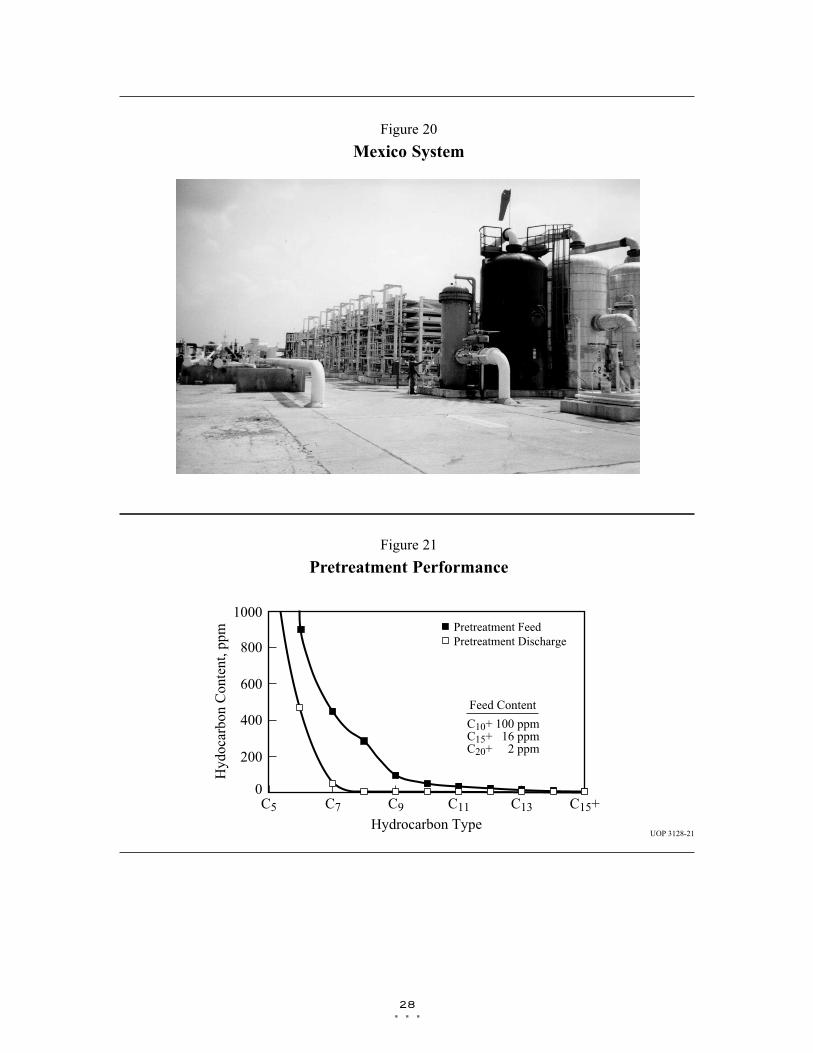
Mexico
UOP recently installed a membrane system in an enhanced oil recovery (EOR) facility inMexico. The system processes 120 MM SCFD of inlet gas containing 70% CO2. The purifiedCO2 gas stream contains 93% CO2 and is reinjected. The hydrocarbon product contains 5% CO2
and is transported to a nearby gas plant for further processing. Figure 20 shows the membranesystem with the pretreatment vessels in the foreground and membrane skids behind them.
The membrane system uses a version of UOP’s advanced pretreatment system and was success-fully started up in July 1997. It continues to meet product specifications. Recent gas analysis hasshown that the pretreatment system continues to exceed expectations. Figure 21 illustrates recent
Figure 19
Qadirpur Membrane System
J J J
28
Figure 20
Mexico System
Figure 21
Pretreatment Performance
UOP 3128-21
C5
Hyd
ocar
bon
Con
tent
, ppm
0
1000
Hydrocarbon Type
600
400
200
Pretreatment FeedPretreatment Discharge800
C7 C9 C11 C13 C15+
Feed Content
C10+C15+C20+
100 ppm16 ppm2 ppm

J J J
29
gas analyses before and after the pretreatment system. The feed gas contained 934 ppm C7+compounds, which were reduced to 55 ppm after the pretreatment. The C9+ content was com-pletely removed.
Salam & Tarek, Egypt
Separex membrane systems soon will be installed in the remote areas of Salam and Tarek,Egypt. These systems consist of three identical units, two for Salam and one for Tarek. Eachsystem is a two-stage unit treating about 100 MM SCFD of natural gas at 65 bar. The CO2 con-tent will be reduced from about 6 to less than 3%.
Because this application requires about 50% CO2 removal, it is on the borderline between requir-ing a one- or two-stage process. The decision was swayed by the client’s requirement that themembrane system produce fuel for the whole plant. The fuel source is the first-stage permeategas, which must be compressed to fuel-supply pressure. Because only marginally more power isneeded to compress the rest of the permeate gas, treating this portion in a second stage and recy-cling it to the first stage makes economic sense.
Reciprocating units were selected for the recycle compressors because they are less expensive,are easier to maintain, and have more readily available spare parts than centrifugal compressors.These features are essential considering the remote location of the plants.
The membrane units are provided with standard pretreatment only because the gas passesthrough dehydration and dew-point control units before entering the membrane system pretreat-ment. Therefore, a heavy hydrocarbon content or condensation in the membranes is not a dan-ger. This arrangement came about because UOP was involved in the project in the early devel-opmental stages. As a result, UOP could advise the client on how to arrange their process to bestsuit all involved. This predesign communication did not occur for the Kadanwari system. As aresult, dew-point control was installed downstream of the membrane and so could not be used toprotect the membrane.
West Texas, USA
Another example of UOP’s broad capabilities is a unit that UOP recently installed in WestTexas. This membrane system processes 30 MM SCFD of 30% CO2 feed gas at an operatingpressure of 42 bar. The product CO2 specification is 10%. The membrane system product gas pro-vides fuel for overall plant operations. This system is similar to the second membrane stagedesigned for both the Salam and Tarek locations.

J J J
30
Conclusions
Membrane systems are a solid and proven addition to the range of technologies for the removalof CO2. With correct pretreatment design, they are extremely reliable, efficient, and ideally suit-ed to installation in remote regions. Continuing enhancements in membranes, membrane sys-tems, and membrane pretreatment makes membranes an even more natural choice in the future,especially for applications requiring higher levels of CO2 removal.

J J J
31
References
1. Chan, A., “Membrane Performance in EOR Applications,” XIII Gas Convention, Valencia,Venezuela, May 1998.
2. Rautenbach, R. and Albrecht, R., “Membrane Processes,” John Wiley and Sons Ltd., 1989.

uop™
UOP LLC25 East Algonquin RoadDes Plaines, IL 60017-5017
UOP 3128 899 GP1