recent developments in small gas turbines -...
TRANSCRIPT
1
Copyright © Siemens AG 2009. All rights reserved.
Recent Developments in Small Industrial Gas turbines
Ian AmosProduct Strategy ManagerSiemens Industrial Turbomachinery LtdLincoln, UK
Page 2 Nov 2010 Energy SectorCopyright © Siemens AG 2009. All rights reserved.
Content
� Gas Turbine as Prime Movers� Applications
� History
� Technology� thermodynamic trends and drivers
� core components
� Future requirements� Market developments
2
Page 3 Nov 2010 Energy SectorCopyright © Siemens AG 2009. All rights reserved.
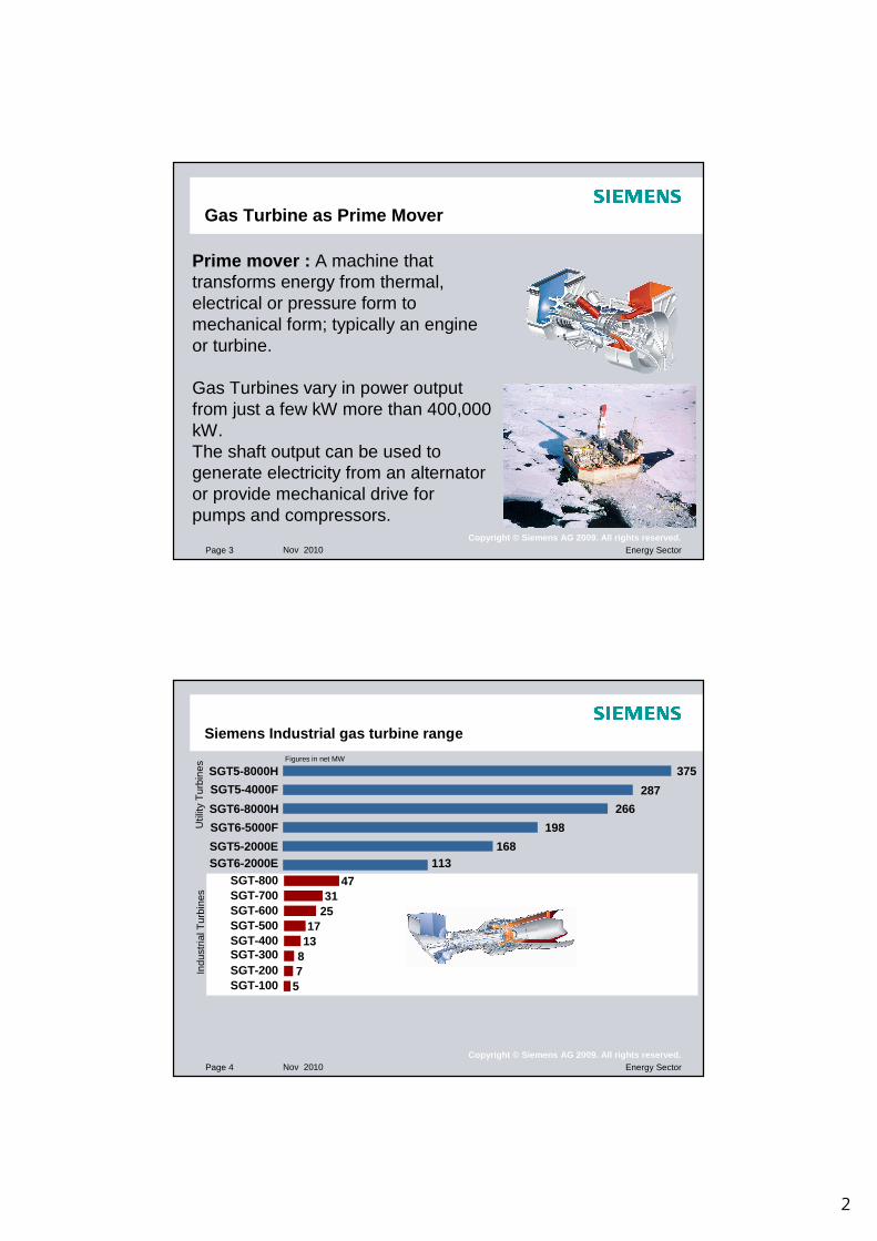
Gas Turbine as Prime Mover
Prime mover : A machine that transforms energy from thermal, electrical or pressure form to mechanical form; typically an engine or turbine.
Gas Turbines vary in power output from just a few kW more than 400,000 kW. The shaft output can be used to generate electricity from an alternator or provide mechanical drive for pumps and compressors.
Page 4 Nov 2010 Energy SectorCopyright © Siemens AG 2009. All rights reserved.
SGT5-4000F
SGT6-5000F
SGT5-2000ESGT6-2000E
SGT-800SGT-700SGT-600SGT-500SGT-400
SGT-200
SGT5-8000H
SGT-100 5
287
198
168
4731
2517
13
7
113
375Figures in net MW
8SGT-300
Indu
stria
l Tur
bine
sU
tility
Tur
bine
s
Siemens Industrial gas turbine range
SGT6-8000H 266

3
Page 5 Nov 2010 Energy SectorCopyright © Siemens AG 2009. All rights reserved.
Industrial Gas Turbine Product Range
47
3025
1713
87
5
SGT-800SGT-700SGT-600SGT-500SGT-400SGT-300SGT-200SGT-100
SGT-100-1S
SGT-400
SGT-300SGT-200-2S
SGT-700 SGT-800SGT-600SGT-500
SGT-100-2S SGT-200-1S Portfolio (MW)
Page 6 Nov 2010 Energy SectorCopyright © Siemens AG 2009. All rights reserved.
An SGT-100 generating set is installed on Norske Shell's Troll Field platform in the North Sea
Thirty SGT-200 driven pump sets on the OZ2 pipeline operated by Sonatrach, Algeria
Power Generation
CHP
Two SGT-400 generating sets operating in cogeneration/ combined cycle for BIEP at BP’s Bulwer Island refinery, Australia
Two SGT-700 driven Siemens compressors for natural gas liquefaction plant owned by UGDC at Port Said, Egypt.
An SGT-800 CHP plant for InfraServBavernwerk’schemical plant in Gendork, Germany.
Compression Comb. Cycle
Industrial Gas TurbineProduct applications
Pumping

4
Page 7 Nov 2010 Energy SectorCopyright © Siemens AG 2009. All rights reserved.
Gas Turbine RefresherComparison of Gas Turbine and Reciprocating Engine C ycle
AIR/FUEL INTAKE COMPRESSION COMBUSTION EXHAUST
Intermittent
AIR INTAKE
COMPRESSION
COMBUSTIONEXHAUST
Continuous
FUEL
Page 8 Nov 2010 Energy SectorCopyright © Siemens AG 2009. All rights reserved.
Gas Turbine as Prime Mover
Operation and Maintenance�No Lubricating oil changes�High levels of availability
Fuel flexibility�Dual fuel capability �Burn Lean gases (high N2 or CO2 mixtures)�Varying calorific values
Size and Weight�High power to weight ratio
giving a very compact power source
Vibration�Rotating parts mean vibration free operation requiring simple foundations
Emissions�Very low emissions of NOx
Gas Turbine Characteristics
5
Page 9 Nov 2010 Energy SectorCopyright © Siemens AG 2009. All rights reserved.
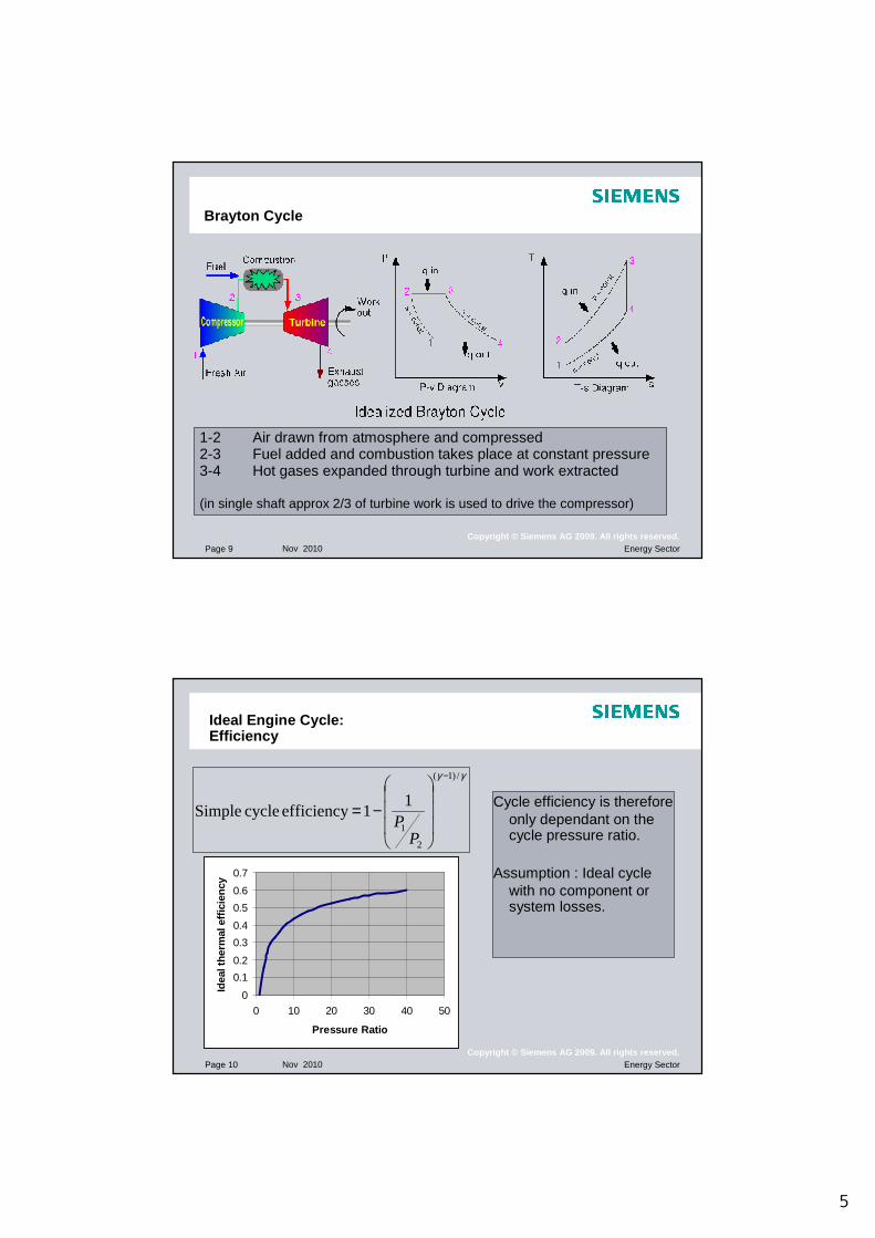
Brayton Cycle
1-2 Air drawn from atmosphere and compressed2-3 Fuel added and combustion takes place at constant pressure3-4 Hot gases expanded through turbine and work extracted
(in single shaft approx 2/3 of turbine work is used to drive the compressor)
Page 10 Nov 2010 Energy SectorCopyright © Siemens AG 2009. All rights reserved.
Ideal Engine Cycle:Efficiency
Cycle efficiency is therefore only dependant on the cycle pressure ratio.
Assumption : Ideal cycle with no component or system losses.
γγ /)1(
2
1
11efficiency cycle Simple
−
−=
PP
0
0.1
0.2
0.3
0.4
0.5
0.6
0.7
0 10 20 30 40 50
Pressure Ratio
Idea
l the
rmal
effi
cien
cy

6
Page 11 Nov 2010 Energy SectorCopyright © Siemens AG 2009. All rights reserved.
Engine Cycle:The Real Engine
Deviations from Ideal Cycle
•Aerodynamic losses in turbine and compressor blading
• Working fluid property changes with temperature
• Pressure losses in intakes, combustors, ducts, exhausts, silencers etc.
• Air used for cooling hot components
• Parasitic air & hot gas leakages
• Mechanical losses in bearings, gearboxes, seals, shafts
• Electrical losses in alternators
‘Real’ Efficiencies
• Practical simple cycle gas turbines achieve 25 to 40 % shaft efficiency
• Complex gas turbine cycles can achieve shaft efficiencies up to 50%
• However, heat rejected in the exhaust can be used :-
•Large combined cycle GT can achieve close to 60% shaft efficiency
•Cogeneration (Heat and Power) can exceed 80% total thermal efficiency
Page 12 Nov 2010 Energy SectorCopyright © Siemens AG 2009. All rights reserved.
Energy Cost SavingsGT cycle parameter study
Increase Pressure ratio and firing temperatures for higher simple cycle efficiencies
35.0
36.0
37.0
38.0
39.0
40.0
41.0
42.0
43.0
280 290 300 310 320 330 340 350 360 370 380 390 400 410 420 430 440 450 460 470 480Shaft Specific Output (kJ/kg)
Sha
ft E
ffici
ency
(%
)
1350ºC1400ºC 1450ºC
25
22
20
18
FIRING TEMPERATURE
PRESSURERATIO
16
14
1300ºC1250ºC
1200ºC

7
Page 13 Nov 2010 Energy SectorCopyright © Siemens AG 2009. All rights reserved.
Design Drivers :Low Specific Fuel Consumption
Higher Pressure Ratios• Increased Cycle Efficiency• Increased number of compressor / turbine stages and
therefore cost
Complex Cycles• Increased Cycle Efficiency and/or Specific Power• Can impact operability, cost and reliability
Higher Firing Temperature• Requires increased sophistication of cooling systems• Can impact life and reliability and combustor emissions
Page 14 Nov 2010 Energy SectorCopyright © Siemens AG 2009. All rights reserved.
Design Drivers :Availabilty, Cost and Emissions
� High reliability.� Moderates the trend to increase firing temperature and cycle
complexity.
� Low Emissions (Driven by environmental legislation)� More difficult to achieve with high firing temperatures and
combustion pressures
� Lowest possible cost.� Encourages smallest possible frame size, i.e. high specific
power� high firing temperature.� Reduced Pressure ratios (< 20:1) to avoid auxiliary fuel
compression costs
Compromise is required in the concept design to get the best balance of parameters

8
Page 15 Nov 2010 Energy SectorCopyright © Siemens AG 2009. All rights reserved.
Pressure Ratio
1616
1515
1414
1313
1212
1111
1010
99
88
77
66
55
44
33
Firing Te
mperature
Firing TemperaturePressu
re Ratio
Pressure Ratio
YearYEARYEARYEARYEAR
3CT
SGT-200
SGT-100
SGT-300
Future
Machines
19501950 19601960 19701970 19801980 19901990 20002000
13001300
12001200
11001100
10001000
900900
800800
700700
Firing Temperature °C
Centrifugal Compr.
TA
TE
TF
TG
TD TB
SGT-400
Core Engine Trends:Key Parameter Trends
Page 16 Nov 2010 Energy SectorCopyright © Siemens AG 2009. All rights reserved.
100
150
200
250
300
350
1975 1980 1985 1990 1995 2000 2005Year
Spe
cific
Pow
er (
kJ/k
g)
24
26
28
30
32
34
36
38
40
The
rmal
Effi
cien
cy (
%)
Specific Power Output
Thermal EfficiencyTB5000
SGT-100
SGT-200
SGT-400
Dramatic impact of increased TET and pressure ratio over last 25 years:• Specific Power increased by almost 100%• Specific Fuel Consumption reduced by over 30%• reduced airflow for a given power output and has resulted in smaller
engine footprints, reduced weight and reduced engine costs
Engine Trends:Thermal Efficiency
9
Page 17 Nov 2010 Energy SectorCopyright © Siemens AG 2009. All rights reserved.
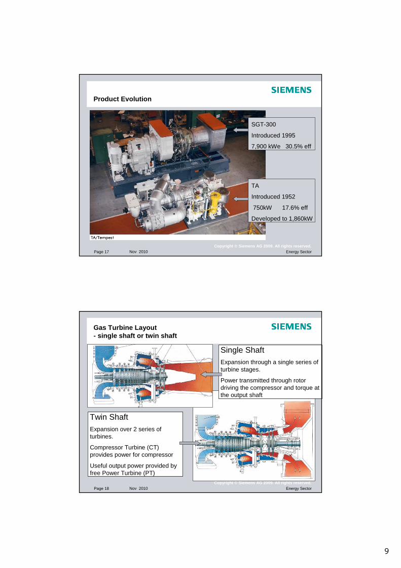
Product Evolution
SGT-300
Introduced 1995
7,900 kWe 30.5% eff
TA
Introduced 1952
750kW 17.6% eff
Developed to 1,860kW
Page 18 Nov 2010 Energy SectorCopyright © Siemens AG 2009. All rights reserved.
Gas Turbine Layout- single shaft or twin shaft
Single ShaftExpansion through a single series of turbine stages.
Power transmitted through rotor driving the compressor and torque at the output shaft
Twin ShaftExpansion over 2 series of turbines.
Compressor Turbine (CT) provides power for compressor
Useful output power provided by free Power Turbine (PT)
10
Page 19 Nov 2010 Energy SectorCopyright © Siemens AG 2009. All rights reserved.
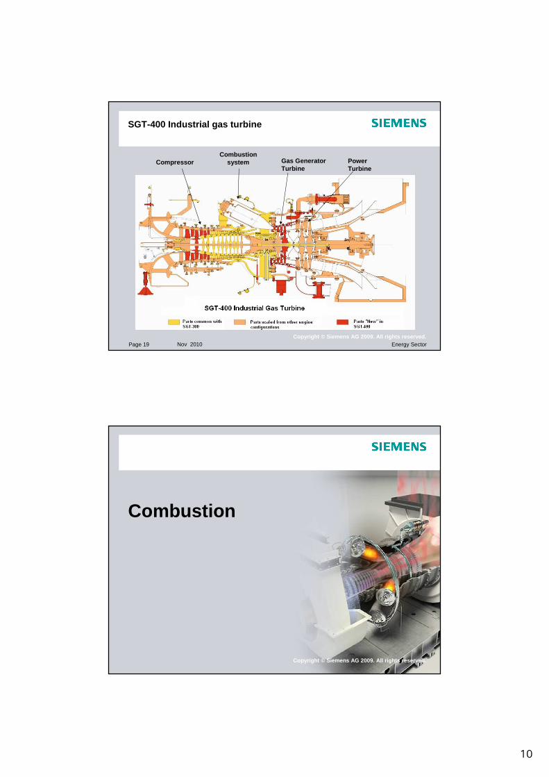
SGT-400 Industrial gas turbine
CompressorCombustion
system Gas GeneratorTurbine
PowerTurbine
Copyright © Siemens AG 2009. All rights reserved.
Combustion

11
Page 21 Nov 2010 Energy SectorCopyright © Siemens AG 2009. All rights reserved.
Environmental AspectsPollutants and Control
Pollutant Effect Method of Control
Carbon Dioxide Greenhouse gas Cycle Efficiency
Carbon Monoxide Poisonous DLE System
Sulphur Oxides Acid Rain Fuel Treatment
Nitrogen Oxides Ozone Depletion Smog
DLE System
Hydrocarbons Poisonous Greenhouse gas
DLE System
Smoke Visible pollution DLE System
DLE - Dry Low Emissions
Page 22 Nov 2010 Energy SectorCopyright © Siemens AG 2009. All rights reserved.
Exhaust Emission Compliance
�Emissions control:� Two types of combustion configuration need to be considered:� Diffusion flame� Dry Low Emissions (DLE or DLN) using Pre-mix combustion
� Diffusion flame� Produces high combustor primary zone temperatures, and as NOx is a
function of temperature, results in high thermal NOx formation� Use of wet injection directly into the primary zone to lower combustion
temperature and hence lower NOx formation
� Dry Low Emissions� Lean pre-mixed combustion resulting in low combustion temperature, hence
low NOx formation� With good design and control <25ppm NOx across a wide load and ambient
range possible
12
Page 23 Nov 2010 Energy SectorCopyright © Siemens AG 2009. All rights reserved.
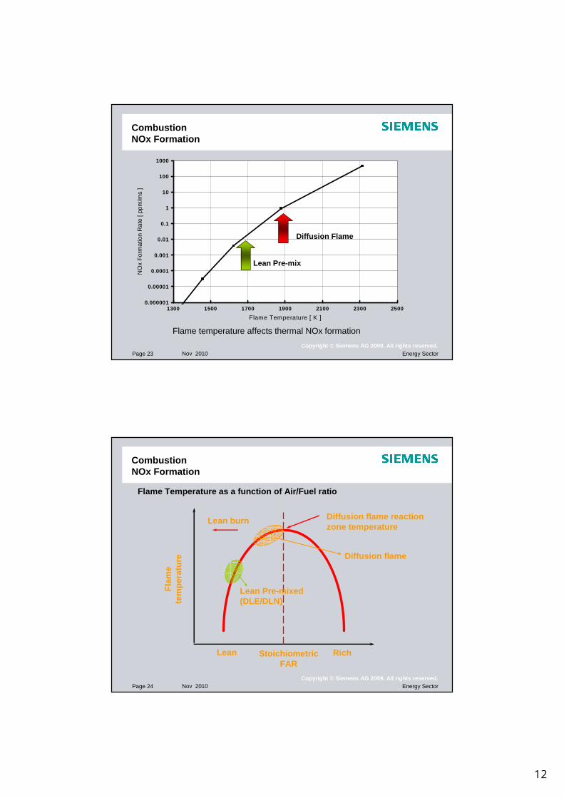
CombustionNOx Formation
0.000001
0.00001
0.0001
0.001
0.01
0.1
1
10
100
1000
1300 1500 1700 1900 2100 2300 2500
Flame Temperature [ K ]
NO
x F
orm
atio
n R
ate
[ ppm
/ms
]
Diffusion Flame
Lean Pre-mix
Flame temperature affects thermal NOx formation
Page 24 Nov 2010 Energy SectorCopyright © Siemens AG 2009. All rights reserved.
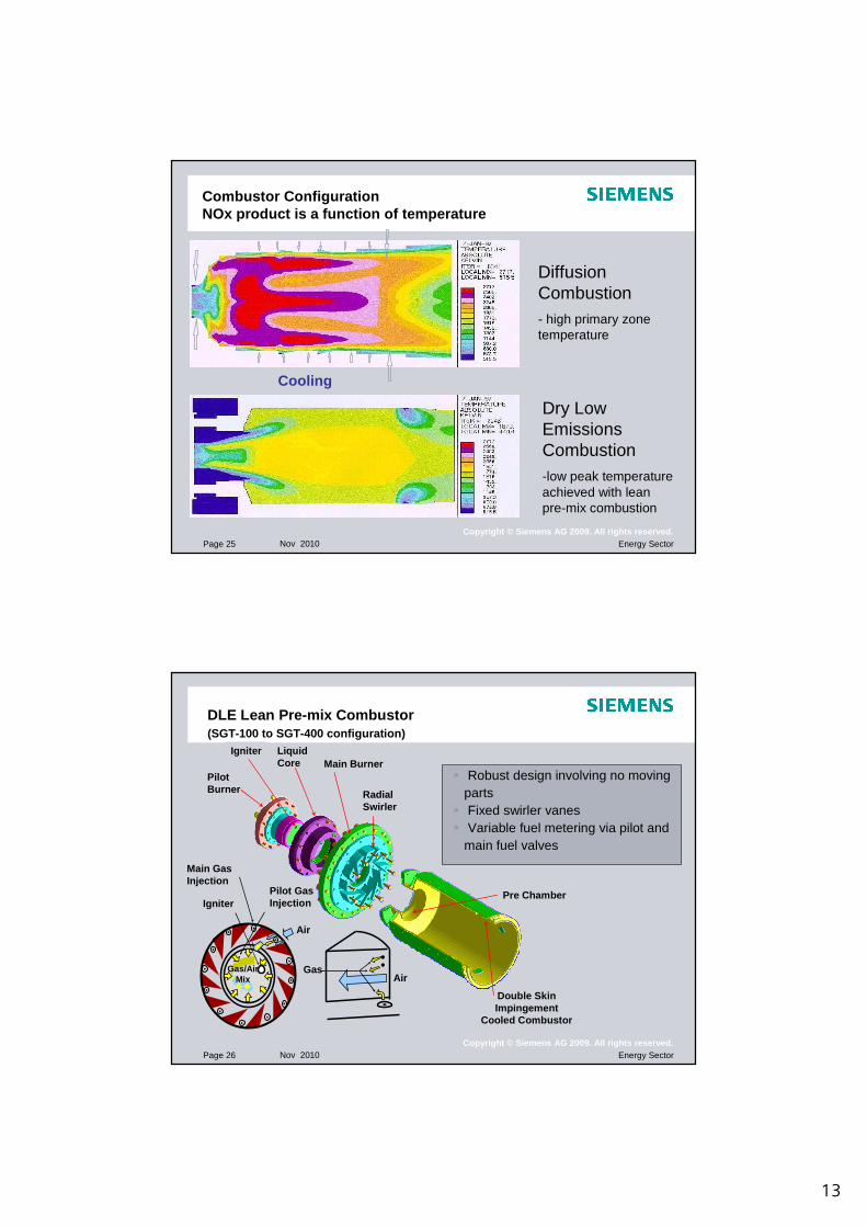
CombustionNOx Formation
RichLean
Lean burn Diffusion flame reactionzone temperature
Fla
me
tem
pera
ture
StoichiometricFAR
Flame Temperature as a function of Air/Fuel ratio
Diffusion flame
Lean Pre-mixed(DLE/DLN)
13
Page 25 Nov 2010 Energy SectorCopyright © Siemens AG 2009. All rights reserved.
Combustor ConfigurationNOx product is a function of temperature
Cooling
Diffusion Combustion- high primary zone temperature
Dry Low Emissions Combustion-low peak temperature achieved with lean pre-mix combustion
Page 26 Nov 2010 Energy SectorCopyright © Siemens AG 2009. All rights reserved.
DLE Lean Pre-mix Combustor(SGT-100 to SGT-400 configuration)
Air
Pilot GasInjection
Air
Main Gas Injection
Igniter
Gas/AirMix
Gas
Pilot Burner
IgniterMain Burner
Liquid Core
Radial Swirler
Double Skin Impingement
Cooled Combustor
Pre Chamber
� Robust design involving no moving parts
� Fixed swirler vanes� Variable fuel metering via pilot and
main fuel valves

14
Page 27 Nov 2010 Energy SectorCopyright © Siemens AG 2009. All rights reserved.
Lean Pre–Mix combustion
�Simple fuel system� Variable fuel metering via pilot and main fuel valves
� Low NOx across a wide operating range of load and ambient conditionsMAIN FLOWCONTROL
VALVE
MAIN MANIFOLD
MBLOCKVALVE
BLOCKVALVE
BLEEDVALVE
PILOT FLOWCONTROL
VALVE
PILOT MANIFOLD
MAIN FLOWCONTROL
VALVE
MAIN MANIFOLD
MBLOCKVALVE
BLOCKVALVE
BLEEDVALVE
PILOT FLOWCONTROL
VALVE
PILOT MANIFOLD
Page 28 Nov 2010 Energy SectorCopyright © Siemens AG 2009. All rights reserved.
Key to success� good mixing of fuel and air
� multiple injection ports around swirler
� long pre-mix path� fuel injection as far from combustion zone as possible
� good air flow distribution� can annular arrangement with top hats
� use of pilot burner� CO control & flame stability
� use of guide vane modulation/air bleed� air flow management
CombustionDLE Lean Premix System
15
Page 29 Nov 2010 Energy SectorCopyright © Siemens AG 2009. All rights reserved.
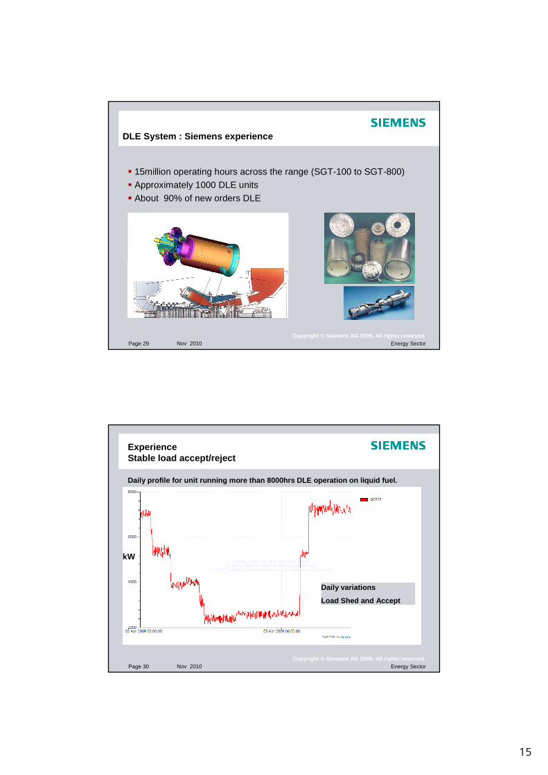
DLE System : Siemens experience
� 15million operating hours across the range (SGT-100 to SGT-800)
� Approximately 1000 DLE units
� About 90% of new orders DLE
Page 30 Nov 2010 Energy SectorCopyright © Siemens AG 2009. All rights reserved.
ExperienceStable load accept/reject
Daily variations
Load Shed and Accept
kW
Daily profile for unit running more than 8000hrs DL E operation on liquid fuel.
16
Page 31 Nov 2010 Energy SectorCopyright © Siemens AG 2009. All rights reserved.
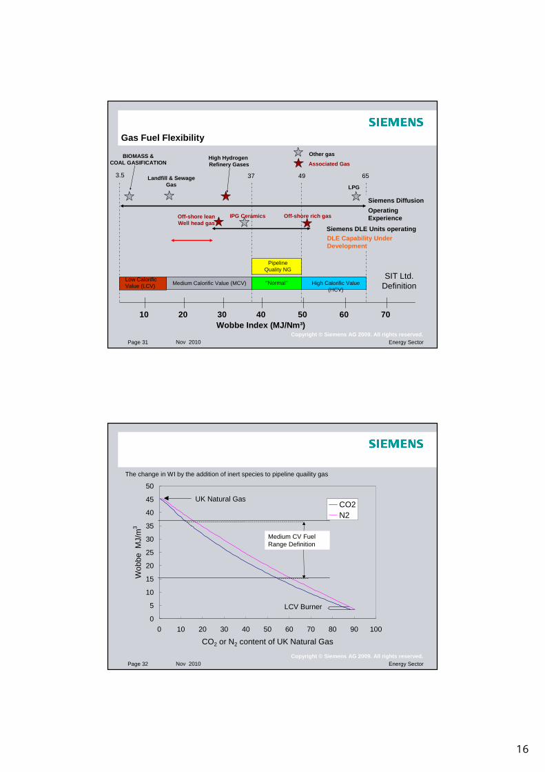
Gas Fuel Flexibility
10 20 40 50 60 7030
Medium Calorific Value (MCV) High Calorific Value (HCV)
‘’Normal’’
Wobbe Index (MJ/Nm³)
SIT Ltd. Definition
Low Calorific Value (LCV)
Pipeline Quality NG
3.5 37 49 65
Siemens DLE Units operatingDLE Capability Under Development
Siemens Diffusion
Operating Experience
BIOMASS &COAL GASIFICATION
Landfill & SewageGas
High Hydrogen Refinery Gases
LPG
Off-shore rich gasIPG CeramicsOff-shore leanWell head gas
Other gas
Associated Gas
Page 32 Nov 2010 Energy SectorCopyright © Siemens AG 2009. All rights reserved.
0
5
10
15
20
25
30
35
40
45
50
0 10 20 30 40 50 60 70 80 90 100
CO2 or N2 content of UK Natural Gas
Wob
be M
J/m
3
CO2N2
MCV development
UK Natural Gas
LCV Burner
The change in WI by the addition of inert species to pipeline quaility gas
Medium CV Fuel Range Definition
17
Page 33 Nov 2010 Energy SectorCopyright © Siemens AG 2009. All rights reserved.
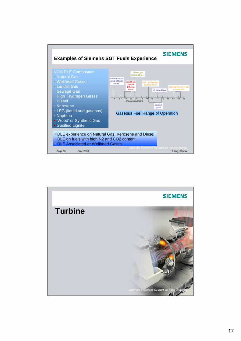
Examples of Siemens SGT Fuels Experience
NON DLE Combustion� Natural Gas� Wellhead Gases � Landfill Gas� Sewage Gas� High Hydrogen Gases� Diesel� Kerosene � LPG (liquid and gaseous)� Naphtha� ‘Wood’ or Synthetic Gas� Gasified Lignite
� DLE experience on Natural Gas, Kerosene and Diesel� DLE on fuels with high N2 and CO2 content. � DLE Associated or Wellhead Gases
5 1 0 15 2 0 25 30 3 5 40 45 5 0 5 5 6 0 6 5 7 0Wobbe Index MJ/m3
Gasified BiomassSpecial Diffusion
burner
Sewage gasstandard burner
High Hydrogen gasstandard burner
Liquified Petroleum gasmodified MPI
standard gases
UK Natural Gas
Landfill gasSpecial
Diffusionburner
Gaseous Fuel Range of Operation
Copyright © Siemens AG 2009. All rights reserved.
Turbine

18
Page 35 Nov 2010 Energy SectorCopyright © Siemens AG 2009. All rights reserved.
Aerodynamic optimised design !
Minimised loss
� optimum pitch/width ratio across whole span.
� low loading� High speed
� high stage number
� low Mach numbers
� thin trailing edges
� low wedge angle
� zero tip clearance
Page 36 Nov 2010 Energy SectorCopyright © Siemens AG 2009. All rights reserved.
AerodynamicsHigh Load Turbine
Computational Fluid Dynamics (CFD) used to complement experimental testing of advanced components.
19
Page 37 Nov 2010 Energy SectorCopyright © Siemens AG 2009. All rights reserved.
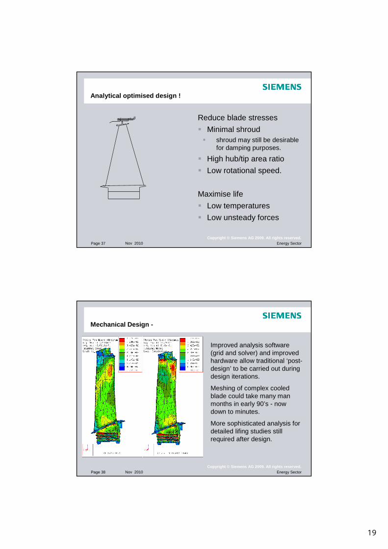
Analytical optimised design !
Reduce blade stresses
� Minimal shroud � shroud may still be desirable
for damping purposes.
� High hub/tip area ratio
� Low rotational speed.
Maximise life
� Low temperatures
� Low unsteady forces
Page 38 Nov 2010 Energy SectorCopyright © Siemens AG 2009. All rights reserved.
Mechanical Design -
Improved analysis software (grid and solver) and improved hardware allow traditional ‘post-design’ to be carried out during design iterations.
Meshing of complex cooled blade could take many man months in early 90’s - now down to minutes.
More sophisticated analysis for detailed lifing studies still required after design.
20
Page 39 Nov 2010 Energy SectorCopyright © Siemens AG 2009. All rights reserved.
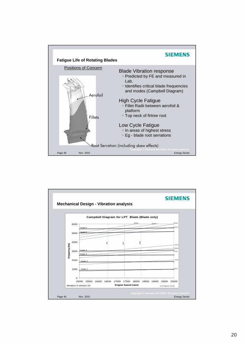
Fatigue Life of Rotating Blades
Positions of Concern
Aerofoil
Fillets
Root Serration (including skew effects)
Blade Vibration response� Predicted by FE and measured in
Lab.� Identifies critical blade frequencies
and modes (Campbell Diagram)
High Cycle Fatigue� Fillet Radii between aerofoil &
platform� Top neck of firtree root
Low Cycle Fatigue� In areas of highest stress� Eg - blade root serrations
Page 40 Nov 2010 Energy SectorCopyright © Siemens AG 2009. All rights reserved.
Mechanical Design - Vibration analysis
Campbell Diagram for LPT Blade (Blade only)
0
1000
2000
3000
4000
5000
6000
15000 15500 16000 16500 17000 17500 18000 18500 19000 19500 20000
Engine Speed (rpm)
Freq
uenc
y (H
z)
D G Palmer 3-8-01Iteration 3 version 10
mode 1
mode 2
mode 3
mode 4
mode 5
mode 6
EO3
EO6
EO9
EO10
EO11
EO17
EO18EO19EO20
100%95%
105%
21
Page 41 Nov 2010 Energy SectorCopyright © Siemens AG 2009. All rights reserved.
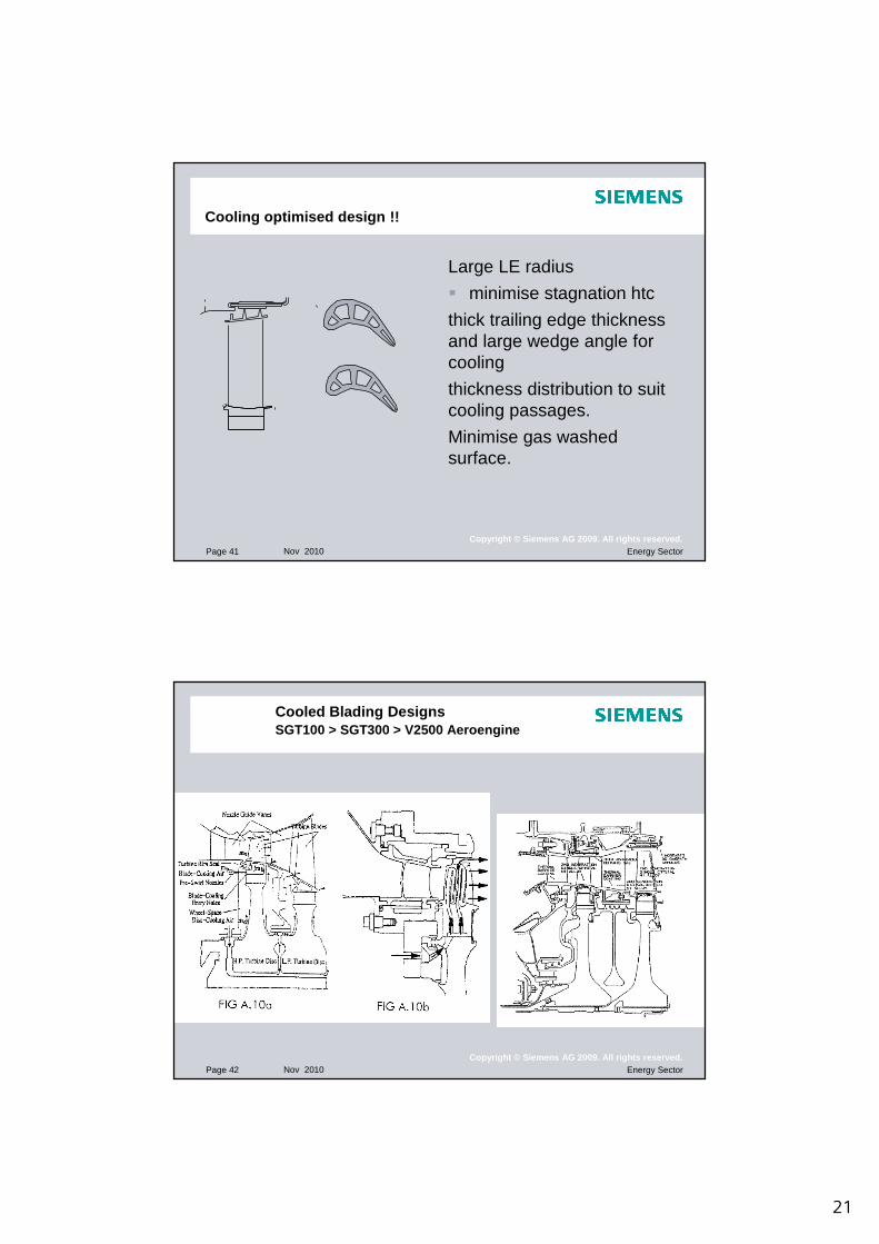
Cooling optimised design !!
Large LE radius
� minimise stagnation htc
thick trailing edge thickness and large wedge angle for cooling
thickness distribution to suit cooling passages.
Minimise gas washed surface.
Page 42 Nov 2010 Energy SectorCopyright © Siemens AG 2009. All rights reserved.
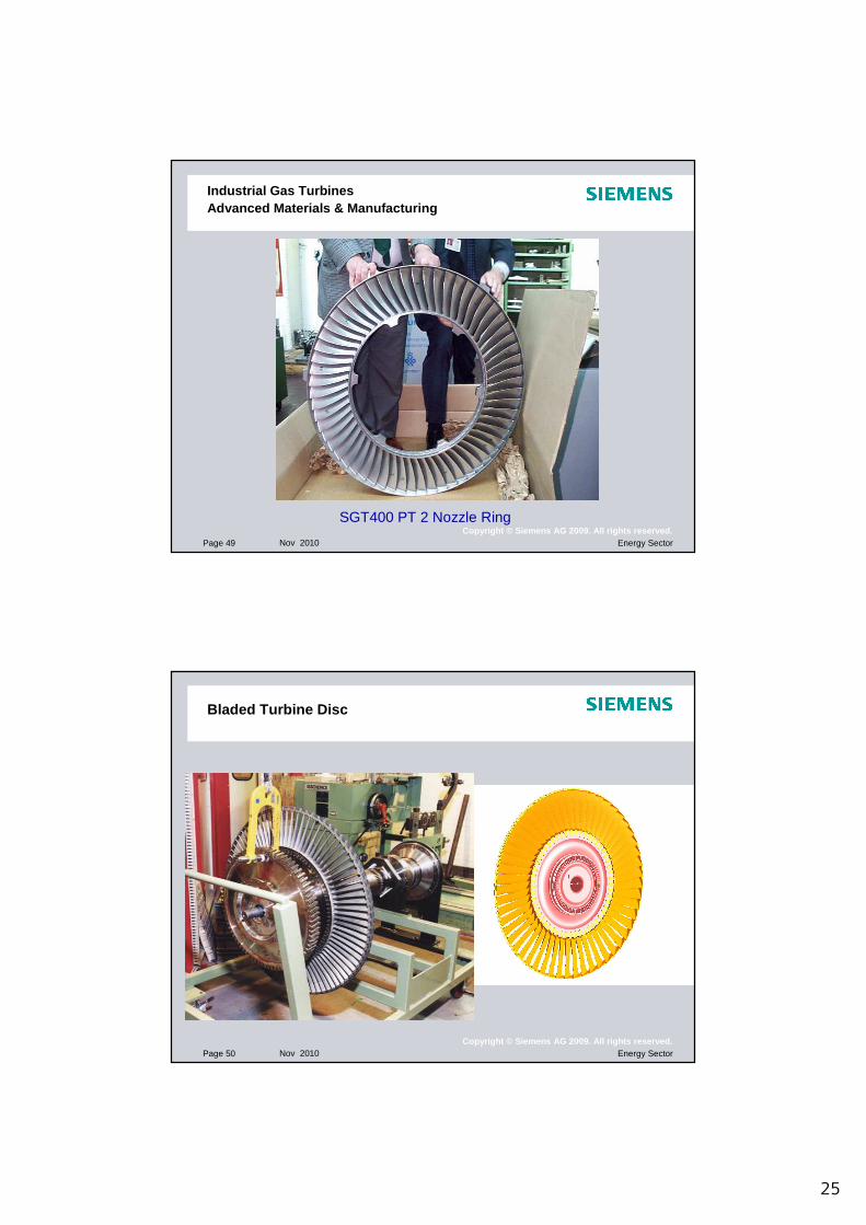
Cooled Blading DesignsSGT100 > SGT300 > V2500 Aeroengine

22
Page 43 Nov 2010 Energy SectorCopyright © Siemens AG 2009. All rights reserved.
SGT400 First Vane Cooling Features
Impingement Cooling
Film Cooling
Turbulators
Trailing Edge Ejection
Cast 2 Vane Segment
Page 44 Nov 2010 Energy SectorCopyright © Siemens AG 2009. All rights reserved.
SGT-400 13MW Industrial Gas TurbineFirst Stage Cooled Vane
Hot Blades are life limited.
-Oxidation
- Thermal fatigue
- Creep
Life typically 24,000 hrs.
Life can be increased or decreased depending on duty and environment.

23
Page 45 Nov 2010 Energy SectorCopyright © Siemens AG 2009. All rights reserved.
SGT300 8MW Industrial Gas TurbineMulti-Pass Cooled First Stage Rotor Blade
SGT-300 First Stage Cooled Rotor Blade
Ceramic Core forming Cooling Passages
Page 46 Nov 2010 Energy SectorCopyright © Siemens AG 2009. All rights reserved.
HP Turbine Blade Coatings
Hot Gas Surface Coatings for Corrosion & Oxidation protection� Aluminide, � Silicon Aluminide (Sermalloy J)� Chromising� Chrome Aluminide, Platinum Aluminide� MCrAlY
Internal Coatings on Cooled Blades operating in poor environments
Ceramic Thermal Barrier Coatings� Yttria stabilised Zirconia� Plasma Spray Coatings used on Vanes� EBPVD Coatings used on rotating blades� More uniform structure for improved integrity

24
Page 47 Nov 2010 Energy SectorCopyright © Siemens AG 2009. All rights reserved.
Turbine Validation Process
Design Analysis
Prototype Test
Assessevaluation and calibration of methods
Page 48 Nov 2010 Energy SectorCopyright © Siemens AG 2009. All rights reserved.
New technology incorporated into existing engine platforms
SGT-100 Product Development
New ratings have been released
Aerodynamic modifications to compressor and turbine.
Power generation, 5.4MWe(launch rating 3.9MWpreviously 5.25MWe)
Mechanical Drive, 5.7MW(previously 4.9MW)
PT
HP Rotor blade• SX4 material• Triple fin shroud• Step Tip seal
Compressor Blade• Stator stages S1& S2• Rotor stages R1 & R2
25
Page 49 Nov 2010 Energy SectorCopyright © Siemens AG 2009. All rights reserved.
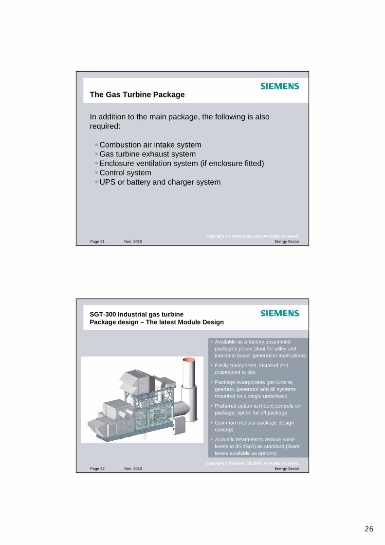
SGT400 PT 2 Nozzle Ring
Industrial Gas Turbines Advanced Materials & Manufacturing
Page 50 Nov 2010 Energy SectorCopyright © Siemens AG 2009. All rights reserved.
Bladed Turbine Disc
26
Page 51 Nov 2010 Energy SectorCopyright © Siemens AG 2009. All rights reserved.
The Gas Turbine Package
In addition to the main package, the following is also required:
�Combustion air intake system�Gas turbine exhaust system�Enclosure ventilation system (if enclosure fitted)�Control system�UPS or battery and charger system
Page 52 Nov 2010 Energy SectorCopyright © Siemens AG 2009. All rights reserved.
SGT-300 Industrial gas turbinePackage design – The latest Module Design
� Available as a factory assembled packaged power plant for utility and industrial power generation applications
� Easily transported, installed and maintained at site
� Package incorporates gas turbine, gearbox, generator and all systems mounted on a single underbase
� Preferred option to mount controls on package, option for off package.
� Common modular package design concept
� Acoustic treatment to reduce noise levels to 85 dB(A) as standard (lower levels available as options)
27
Page 53 Nov 2010 Energy SectorCopyright © Siemens AG 2009. All rights reserved.
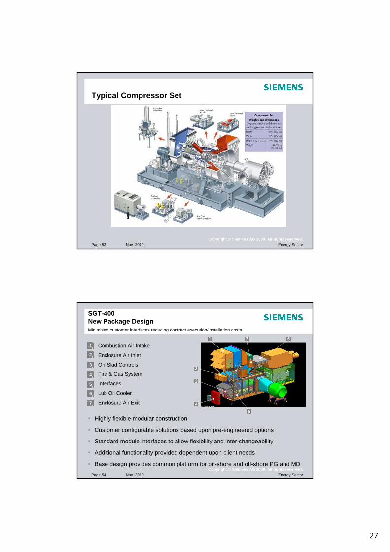
Typical Compressor Set
Page 54 Nov 2010 Energy SectorCopyright © Siemens AG 2009. All rights reserved.
Combustion Air Intake
Enclosure Air Inlet
On-Skid Controls
Fire & Gas System
Interfaces
Lub Oil Cooler
Enclosure Air Exit
1
2
3
4
5
6
7
SGT-400New Package Design Minimised customer interfaces reducing contract execution/installation costs
1
2
3
4
5
67
� Highly flexible modular construction
� Customer configurable solutions based upon pre-engineered options
� Standard module interfaces to allow flexibility and inter-changeability
� Additional functionality provided dependent upon client needs
� Base design provides common platform for on-shore and off-shore PG and MD
28
Copyright © Siemens AG 2009. All rights reserved.
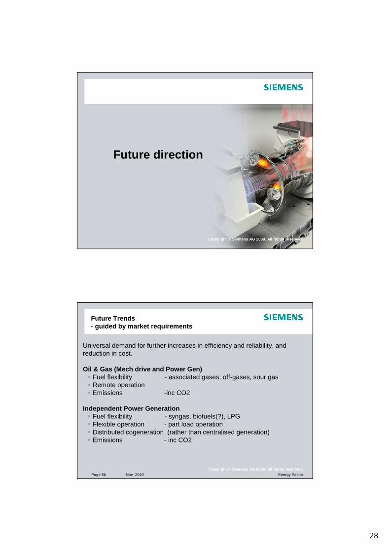
Future direction
Page 56 Nov 2010 Energy SectorCopyright © Siemens AG 2009. All rights reserved.
Future Trends- guided by market requirements
Universal demand for further increases in efficiency and reliability, and reduction in cost.
Oil & Gas (Mech drive and Power Gen)� Fuel flexibility - associated gases, off-gases, sour gas� Remote operation� Emissions -inc CO2
Independent Power Generation� Fuel flexibility - syngas, biofuels(?), LPG � Flexible operation - part load operation� Distributed cogeneration (rather than centralised generation) � Emissions - inc CO2

29
Page 57 Nov 2010 Energy SectorCopyright © Siemens AG 2009. All rights reserved.
Oil and Gas remote operations / fuel flexibility
•First application of its kind in Russia (Western Siberia) burning wellhead gas which was previously flared•Solution:
Three SGT-200 gas turbine•Output 6.75 MWe each•DLE Combustion system•Guaranteed NOx and CO emission levels of 25ppm•Min. air temp. (-57oC)•Max. air temp. (+34oC)
•Gas composition with Wobbe Index >45MJ/m3
•Total DLE hours approximately 22,300 hours for each unit•Significant reduction of emissions : 80-90% reduction of NOx level•Siemens has supplied 135 gas turbines for Power Generation , Gas compression and pumping duty throughout the Russian oil & gas industry
Page 58 Nov 2010 Energy SectorCopyright © Siemens AG 2009. All rights reserved.
Power Generationre-emergence of cogeneration
BOILEROR
DRIER
GRID
WATER
FUEL
PRODUCT / STEAM
~
30
Page 59 Nov 2010 Energy SectorCopyright © Siemens AG 2009. All rights reserved.
Thank You