reciprocating compressor installation and validation -...
TRANSCRIPT
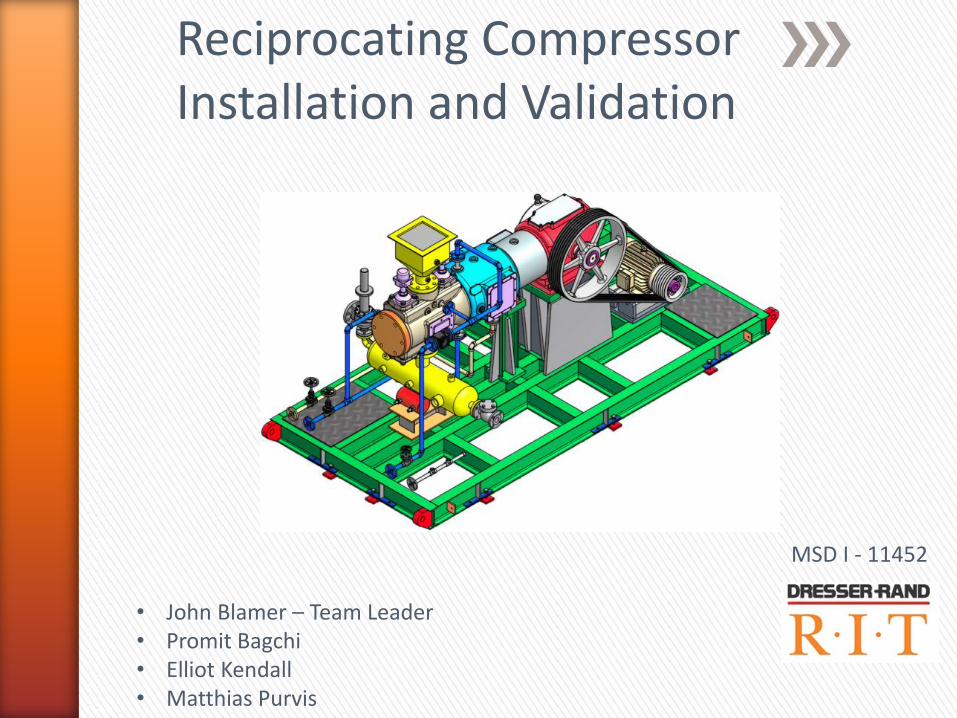
Reciprocating Compressor Installation and Validation
MSD I - 11452
• John Blamer – Team Leader • Promit Bagchi • Elliot Kendall • Matthias Purvis
Finalized Designs:
Customer Needs
Compressor Mounting
Cooling System
Data Acquisition
T-zero & “Life” Test Plans
Labs
Bill of Materials
Arrival Task Plan
Risk Mitigation (Plan A, B, and C)
MSD II Schedule
Delivery Check List
Power Up Check List
Complete Installation Checklist
Post Delivery
Maintenance Hints
Safety Recommendations
» Agenda

» Finalized Design - Customer Needs

• Attaching vibration mounts → skid
• Adapter plate
• Method of attachment
• Welding, bolts, clamps
• Access to inner I-beam flange
• Attaching vibration mounts → floor
• Bolts through floor
• Epoxy
• Concrete anchors
• Combination
» Finalized Design - Mounting

» Finalized Design - Mounting - Selected Mounting Method
• Steel adapter plates
• Counter-bored bolts → vibration mount
• Threaded holes → I-beam flange
• Attaching mounts to floor
• Two bolts per mount
• Bolt through floor slab
Floor
Mount
Skid
Bolts
Adapter

» Finalized Design - Mounting - Adapter Plates
Outer viewpoint
Inner viewpoint
• ½-20 x ¾” Grade 8 Bolts
• 4 per mount
• 4 x 10 mounts = 40 bolts
• 40 Washers
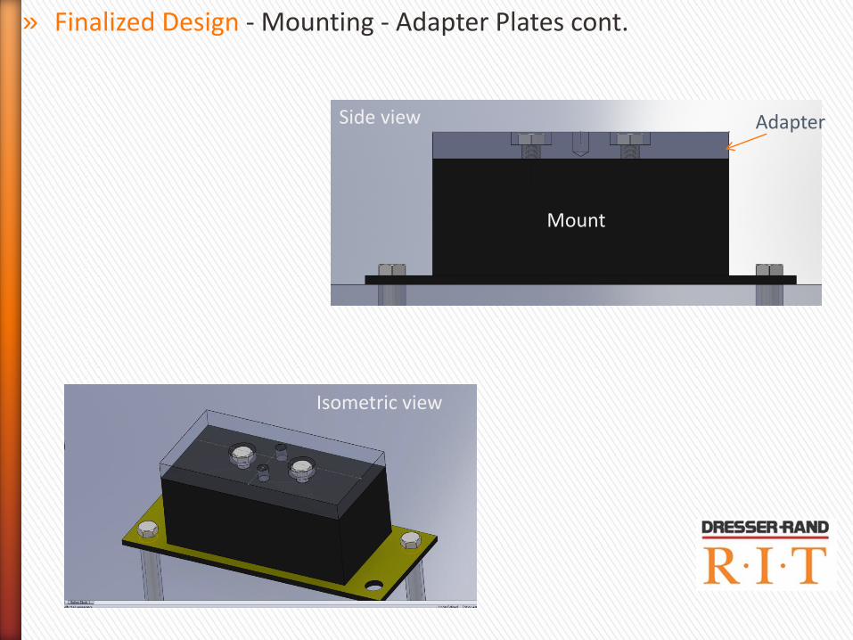
» Finalized Design - Mounting - Adapter Plates cont.
Side view
Mount
Adapter
Isometric view
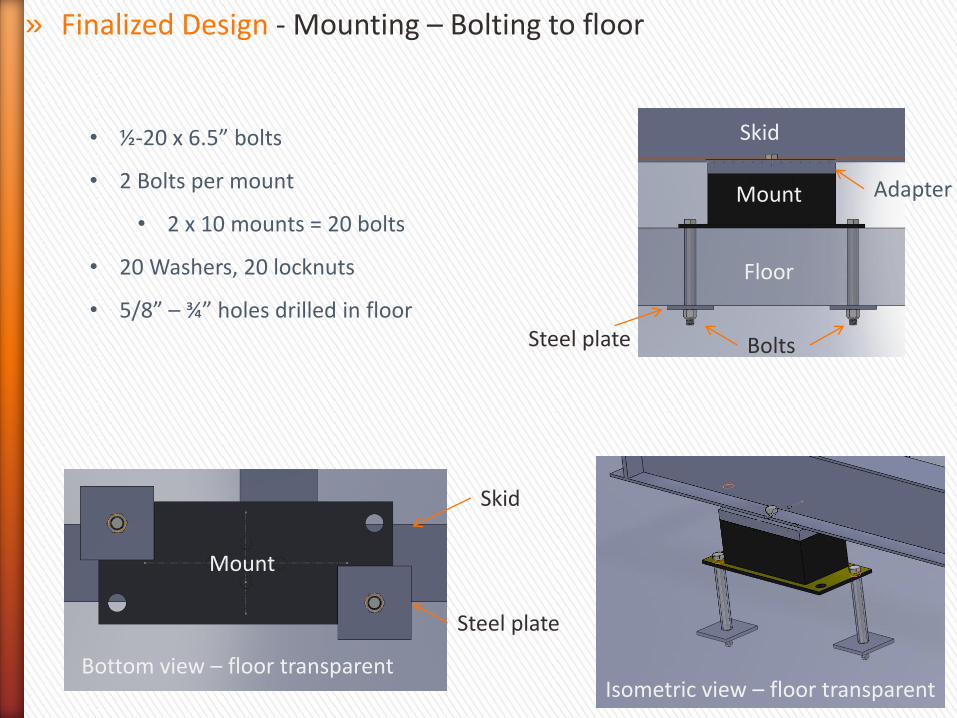
» Finalized Design - Mounting – Bolting to floor
Floor
Mount
Skid
Bolts
Adapter
Bottom view – floor transparent
Mount
Steel plate
Isometric view – floor transparent
Steel plate
Skid
• ½-20 x 6.5” bolts
• 2 Bolts per mount
• 2 x 10 mounts = 20 bolts
• 20 Washers, 20 locknuts
• 5/8” – ¾” holes drilled in floor

• Construct new cooling system
• High head - multi stage - Industrial Booster Pump
• Spa pump
• Multi-stage centrifugal pump
• Time consuming, expensive
• Utilize Mr. Wellin’s existing system
• Insufficient head
• Replace electric motor, 2X RPM
• Reusing existing Dept. materials
• Saving money
» Finalized Design - Cooling System – Development Process
High Head – multi stage pump
Spa pump Multi-stage centrifugal pump
Wellin’s pump system
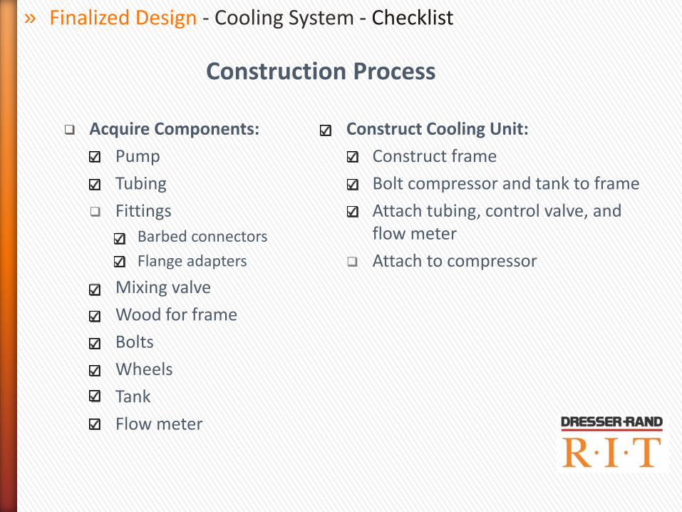
Acquire Components:
Pump
Tubing
Fittings
Barbed connectors
Flange adapters
Mixing valve
Wood for frame
Bolts
Wheels
Tank
Flow meter
Construct Cooling Unit:
Construct frame
Bolt compressor and tank to frame
Attach tubing, control valve, and flow meter
Attach to compressor
Construction Process
» Finalized Design - Cooling System - Checklist

» Pump - .33 hp, 3450 RPM, 92 psi
» Mixing Valve - 70° to 100°F thermostatic valve
» Tank - 50 gallon Polyethylene tank
» Finalized Design - Cooling System – System Diagram

Calibration and Testing
Initial flow rate Adjustment:
Start coolant circulation pump and read flow rate from flow meter.
Adjust flow control valve to achieve a flow of 4 gpm.
Temperature Calibration:
Measure mixing valve output temperature with thermocouple and data logger or thermometer.
Adjust mixing valve to produce an output temperature of 80° F
Use a thermocouple and data logger to record mixing valve output temperature from cold startup to steady state operation to verify accurate operation.
» Finalized Design - Cooling System - Calibration and Testing
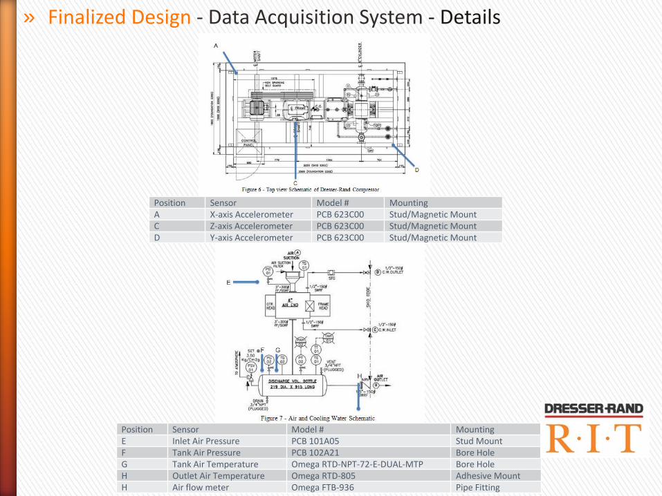
Position Sensor Model # Mounting
A X-axis Accelerometer PCB 623C00 Stud/Magnetic Mount C Z-axis Accelerometer PCB 623C00 Stud/Magnetic Mount D Y-axis Accelerometer PCB 623C00 Stud/Magnetic Mount
Position Sensor Model # Mounting
E Inlet Air Pressure PCB 101A05 Stud Mount F Tank Air Pressure PCB 102A21 Bore Hole
G Tank Air Temperature Omega RTD-NPT-72-E-DUAL-MTP Bore Hole
H Outlet Air Temperature Omega RTD-805 Adhesive Mount H Air flow meter Omega FTB-936 Pipe Fitting
» Finalized Design - Data Acquisition System - Details

Stud Mount
Magnetic Mount
Adhesive Mount
Screw Mount
» Finalized Design - Data Acquisition System - Details

Research sensor’s listed from P09452. Make sure that the sensor’s do not exceed the 8 analog input slots in the existing DAQ system.
Install the existing DAQ system onto the LabView Computer Run and secure all cabling to sensors/signal conditioners to the
LabView computer. On the Labview computer, configure the LabView Compressor
Project to accept all the sensors. All the random number generators will have to be replaced, and all the sensors will need to be calibrated.
Test the DAQ to ensure it is measuring the correct information.
» Finalized Design - Data Acquisition System

Turn on computer and DAQ System.
Turn on compressor
Wait for the compressor to reach operating temp.
Measure each parameter at least 3 times. • Flow at discharge
• Temperature at discharge
• Pressure at discharge
• Transmissibility
Take an average of each parameter.
Calculate BHP.
Record averages and plot results. Beginning of life characterization of compressor performance data - complete
Compare with Dresser Rand’s Specifications. Calculate percent difference between P11452’s experimental results and given specifications.
Validation of specifications - complete
Give results to Dr. Kolodziej • Dr. Kolodziej may start his research
» Post Delivery - T-zero and “life” Test Plans
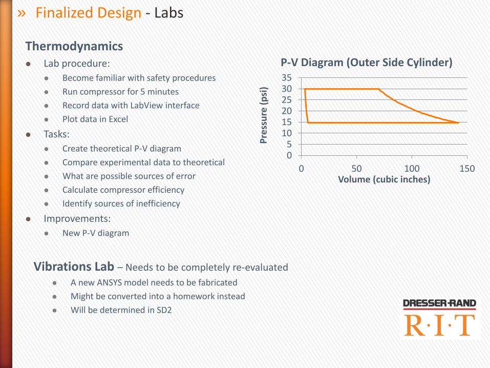
Thermodynamics Lab procedure:
Become familiar with safety procedures
Run compressor for 5 minutes
Record data with LabView interface
Plot data in Excel
Tasks:
Create theoretical P-V diagram
Compare experimental data to theoretical
What are possible sources of error
Calculate compressor efficiency
Identify sources of inefficiency
Improvements:
New P-V diagram
05
101520253035
0 50 100 150
Pre
ssu
re (
psi
)
Volume (cubic inches)
P-V Diagram (Outer Side Cylinder)
» Finalized Design - Labs
Vibrations Lab – Needs to be completely re-evaluated
A new ANSYS model needs to be fabricated
Might be converted into a homework instead
Will be determined in SD2

» Finalized Design - Bill of Materials
Part Name Material Manufacturer Manufacturer Part # Distributor Distributor
Part #
Quantity Needed Unit
MFG
Time
(hrs)
Total
MFG
Time
(hrs)
Quantity
Ordered
Unit Price Total Price Lead
Time
Owner Status Comments
Coolant Circulation Pump
Motor
Baldor JL3405A Baldor JL3405A 1 0 0 1 $263.00 $ 263.00 1 wk Elliot arrived
Barbed Tubing Fittings copper Home Depot 2 0 0 0 Elliot
Mixing Valve Bronze Honeywell AM-101 McMaster-Carr 9156K12 1 0 0 1 $107.12 $ 107.12 1 wk Elliot arrived
Flange Connectors Forged Steel McMaster-
Carr
68095K122 McMaster-Carr 68095K122 2 0 0 2 $15.27 $ 30.54 1 wk Elliot arrived
Signs Matt
Glasses Matt
Ear Plugs Matt
Steel for Adapters 3/4" Hot
Rolled
Rochester
Steel
Rochester Steel 2 2 $79.67 $ 159.34 2 days Promit arrived
Nuts (floor to mount) McMaster-Carr 90630A160 Promit
Bolts (floor to mount) McMaster-Carr 91257A490 PromitNuts McMaster-Carr Promit
Bolts McMaster-Carr Promit
X-axis Acceleromter PCB 623C00 John
Y-axis Acceleromter PCB 623C00 John
Z-axis Acceleromter PCB 623C00 John
Inlet Air Pressure PCB 101A05 John
Tank Air Pressure PCB 102A21 John
Tank Air Temperature Omega RTD-NPT-72-E-
Dual-MTP
John
Outlet Air Temperature Omega RTD-805 John
Air Flow Meter Omega FTB-936 John
Tool Chest All
Boulter Services All
Legend
Mis
cD
AQ
Co
oli
ng
Sy
ste
m
Bill of Materials
Do not know all info.
Sa
fety
Mo
un
tin
g
Ready to order
Ordered

» Arrival Task Plan - Risk Mitigation (Plan A, B & C)
Plan A – Compressor Arrives in Fall Quarter
Plan C – Compressor Does Not Arrive
Plan B – Compressor Arrives in Winter Quarter

» Post Delivery – MSD II Schedule
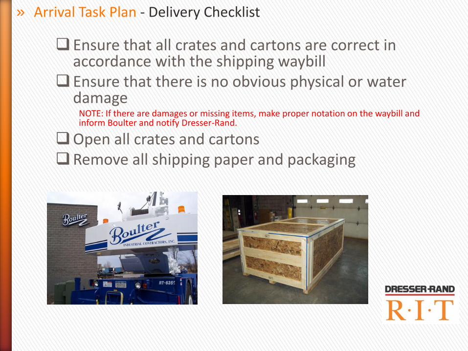
Ensure that all crates and cartons are correct in accordance with the shipping waybill
Ensure that there is no obvious physical or water damage
NOTE: If there are damages or missing items, make proper notation on the waybill and inform Boulter and notify Dresser-Rand.
Open all crates and cartons Remove all shipping paper and packaging
» Arrival Task Plan - Delivery Checklist

Remove rust preventative with an acceptable solvent Assemble compressor components Purge the entire gas piping system and compressor with nitrogen or other
dry inert gas NOTE: There should be a slight positive pressure charge left on the piping system at all times to keep the system free of air.
Measure and compare spacing of bolts, damper holes, and skid holes. Align and level the compressor Mark holes on floor Move compressor, drill holes, move compressor back in Hold the final position by snugging the bolts evenly against the skid base.
NOTE: Check with a level to make sure the machine does not shift. Do not attempt to level the unit by tightening to the foundation bolt nuts as this can distort the skid.
» Arrival Task Plan - Boulter Installation Checklist
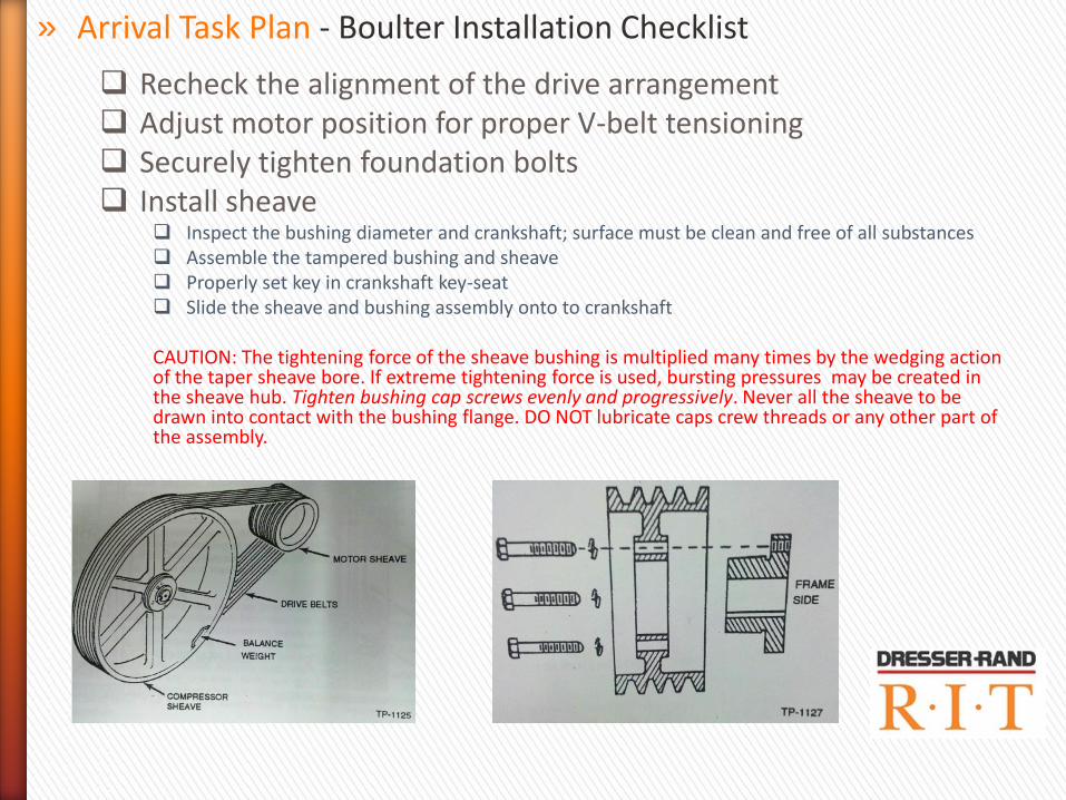
Recheck the alignment of the drive arrangement Adjust motor position for proper V-belt tensioning Securely tighten foundation bolts Install sheave
Inspect the bushing diameter and crankshaft; surface must be clean and free of all substances Assemble the tampered bushing and sheave Properly set key in crankshaft key-seat Slide the sheave and bushing assembly onto to crankshaft CAUTION: The tightening force of the sheave bushing is multiplied many times by the wedging action of the taper sheave bore. If extreme tightening force is used, bursting pressures may be created in the sheave hub. Tighten bushing cap screws evenly and progressively. Never all the sheave to be drawn into contact with the bushing flange. DO NOT lubricate caps crew threads or any other part of the assembly.
» Arrival Task Plan - Boulter Installation Checklist
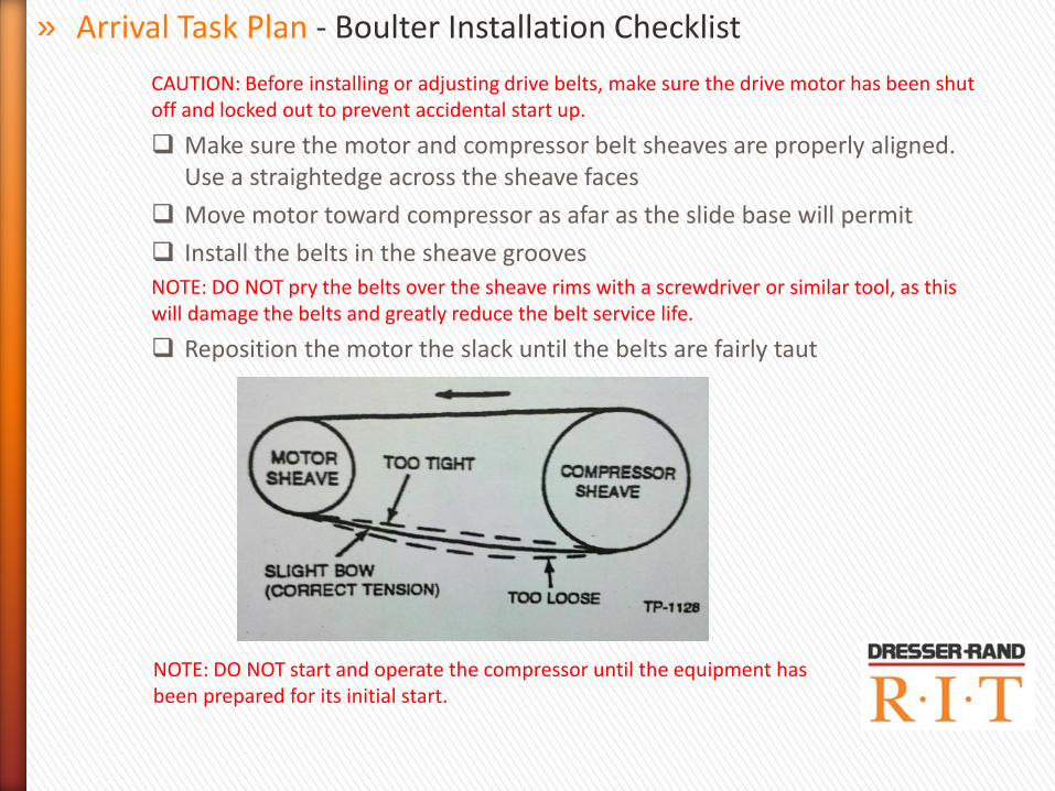
CAUTION: Before installing or adjusting drive belts, make sure the drive motor has been shut off and locked out to prevent accidental start up.
Make sure the motor and compressor belt sheaves are properly aligned. Use a straightedge across the sheave faces
Move motor toward compressor as afar as the slide base will permit
Install the belts in the sheave grooves NOTE: DO NOT pry the belts over the sheave rims with a screwdriver or similar tool, as this will damage the belts and greatly reduce the belt service life.
Reposition the motor the slack until the belts are fairly taut
» Arrival Task Plan - Boulter Installation Checklist
NOTE: DO NOT start and operate the compressor until the equipment has been prepared for its initial start.

Install the belt guard Start the drive motor and observe the belt tension.
There should be a slight “bow” on the slack side of the drive.
If adjustment is required, shut off and lock out the motor, then reposition the motor. The belts may need readjusting after a few days of operation after they seat themselves in the sheave grooves
» Arrival Task Plan - Boulter Installation Checklist
» Prior to First Run
E-Stops Ensure power is connected to the control unit by using a voltmeter to check
power supply to the control unit. Press the E-Stop button located in the front of the room. Ensure that the control unit has lost power. Reset the circuit breaker. Press the E-Stop button located in the back of the room. Ensure that the control unit has lost power. Reset the circuit breaker. Press the E-Stop button located outside of the room. Check that the control unit has lost power. Reset the circuit breaker.
» Arrival Task Plan - Power up Checklist

» Lock-Out Tag-Out for Control Panel Pull down the power lever to shut down the main circuit breakers. Use the lock-out tag-out lock to ensure the lock-out lever is restricted
from moving. Turn on the control panel. Use a multi-meter to check that the control panel is not receiving power. Turn off the control panel. Un-lock the lock-out lever. Pull the power lever up to return power to the main circuit breakers.
» Arrival Task Plan - Power up Checklist

» Arrival Task Plan – Complete Installation Checklist

Idle belts should appear snug. In motion and under load, they should have a slight bow on the slack side.
Avoid excessive heat. Above 140°F (60°C) rubber is over cured and belt life is shortened. Keep belts well ventilated to avoid heat buildup.
Never intermix belts or replace less than a complete set of belts. CAUTION: Always replace drive belts as a complete matched set, since a new unstretched belt installed independently will carry an unequal share of the load and possibly break.
Never use belt dressing. Worn and/or misaligned sheaves reduce belt life.
Check sheaves periodically.
» Post Delivery - Maintenance Hints
Periodically examine the belts for fraying, cracking, or softening. Press on each belt to see it all the belts have the same tension. If one or more belts are defective, the entire belt set must be replaced.
Keep belts oil-free. Excessive oil on belts causes rubber to swell and belts to fail prematurely.
Never force belts onto sheaves; release the belt take-up by moving the motor toward the compressor.
Equalize belt slack before tensing, either all on the top or all on the bottom. CAUTION: If left on equipment during an extended shutdown, the belts can acquire a permanent “set” which may greatly increase the possibility of failure.
» Post Delivery - Maintenance Hints
If the compressor is shut down and is to remain idle for an extended period, the drive belts should be removed and stored in a cool, dry location. The best method of storing belts is to hang them uncoiled over pegs on a wall or rack. If belts become water-soaked, or are piled on a damp floor, undue shrinking may occur. WARNING: NEVER operate belt driven equipment without adequate guarding installed in conformance with OSHA, State and/or local standards and codes in effect at the compressor site
CAUTION: It is extremely important that the compressor intake piping be thoroughly cleaned. If metal pieces, pipe scale, rust, welding spatter, dirt, and all foreign material are not carefully and completely removed, they will be loosened by the flow of air or gas and will cause serious damage. Blow the piping out with high pressure air after cleaning.
» Post Delivery - Maintenance Hints

» Review all safety procedures in operating manual.
» Identify all reciprocating components, electrical hazards, pinch-points, rotating parts, and pressurized equipment.
» Maintain daily operating procedures
» Post Delivery - Safety Recommendations

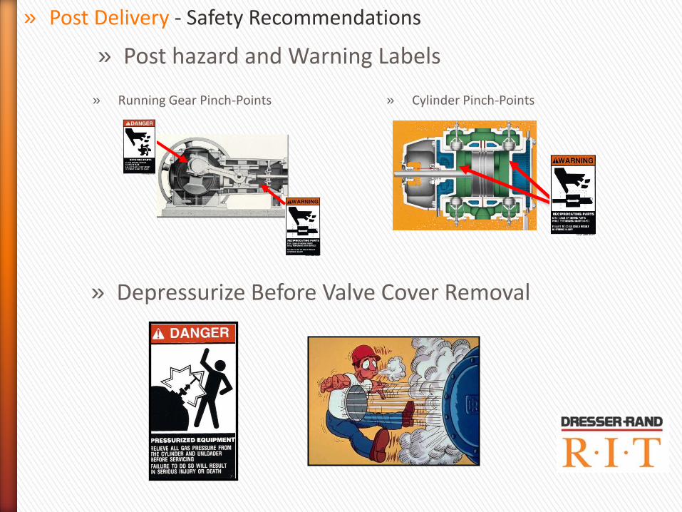
» Post hazard and Warning Labels
» Post Delivery - Safety Recommendations
» Pinch-Point Electric Motor Drive Belts » Pressurized Valve Cover
» Hot Discharge Temperatures: Compressor Cylinder & Discharge Bottle » Electric Motor Shock Hazard
» Post Delivery - Safety Recommendations
» Post hazard and Warning Labels
» Running Gear Pinch-Points
» Cylinder Pinch-Points
» Depressurize Before Valve Cover Removal

» LOCKOUT, TAG-OUT ELECTRICAL POWER
» Appropriate Safety Gear ˃ Safety glasses or goggles
˃ Gloves
˃ Ear protection
» Post Delivery - Safety Recommendations

» Be careful where you place your hands and finger when tightening the piston rod jam-nut with hammer wrench
» Post Delivery - Safety Recommendations