recommendation n. era-rec-127-2017/rec of the … · recommendation annex ito era-rec-127-2017/rec...
TRANSCRIPT

Recommendation
ERA-REC-127-2017/REC
EUROPEAN V1.O
UNIONAGENCYFOR RAILWAYS
Making the railway systemwork better for society.
RECOMMENDATION N. ERA-REC-127-2017/RECOFTHE EUROPEAN UNION AGENCY FOR RAILWAYS
on
Closing of Open Points and additional modifications in theCommission Regulation (EU) No. 1299/2014 of 18 November 2014on the technical specifications for interoperability relating to the‘infrastructure’ subsystem of the rail system in the European Union(‘INF TSI’)
120 Rue Marc Lefrancq I BP 20392 I FR-59307 Valenciennes cedex V 1 / 3Tel. +33 (0)32709 6500 I era.europa.eu


EUROPEAN UNION AGENCY FOR RAILWAYS Recommendation
ERA-REC-127-2017/REC
v1.0
THE EXECUTIVE DIRECTOR
HAVING REGARD TO Regulation (EU) 2016/796 of the European Parliament and of the Council of 11 May2016 on the European Union Agency for Railways and repealing Regulation (EC) No 881/2004, hereafterreferred to as the ‘Agency Regulation’, in particular Articles 4 and 19 thereof,
HAVING REGARD TO Directive (EU) 2016/797 of the European Parliament and of the Council of 11 May 2016on the interoperability of the rail system (Recast), hereafter referred to as the ‘Interoperability Directive’, inparticular Article 5 thereof,
HAVING REGARD TO Commission delegated Decision (EU) 2017/1474 of 8 June 2017 supplementing Directive(EU) 2016/797 of the European Parliament and of the Council with regard to specific objectives for thedrafting, adoption and review of technical specifications for interoperability, in particular Article 3 thereof
Whereas
1. According to the provisions of Article 19 of the Agency Regulation, one of the tasks of the Agency
is to ‘address recommendations to the Commission on the TSIs and their revision, in accordance with
Article 5 of Directive (EU) 2016/797’.
2. In accordance with its Work Programme, the Agency has examined the technical specifications for
interoperability relating to the ‘infrastructure’ subsystem of the rail system in the European Union
(‘INF TSI’) 1 in order to identify the most appropriate way of closing several open points.
3. In order to improve clarity of the INE TSI, additional modifications have been identified. These
modifications do not introduce nor modify existing requirements.
4. The proposed amendments have been discussed with a working party established for this purpose
in accordance with Article 5 of the Agency Regulation.
5. The proposed amendments have no direct impact on the social environment or working conditions
of workers in the industry, nor on the rail freight customers or passengers. Therefore, no
consultation of neither social partners nor rail freight customers and passengers, as provided for in
Articles 6 and 7 of the Agency Regulation, correspondingly, is necessary.
6. An impact assessment in accordance with Article 5(3) of the Interoperability Directive has been
carried out in respect to the amendments proposed in this Recommendation.
HAS ADOPTED the following recommendation:
1. The Annex to Commission Regulation (EU) 1299/2014 concerning the technical specification for
interoperability relating to ‘infrastructure’ subsystem of rail system in the European Union should
be amended as set out in Annex 1 to this Recommendation
1 Commission Regulation (EU) No 1299/2014 of 18 November 2014 on the technical specifications forinteroperability relating to the ‘infrastructure’ subsystem of the rail system in the European Union (OJ L356,12.12.2014 p1).
120 Rue Marc Lefrancq I BP 20392 I FR-59307 Valenciennes Cedex 2 / 3Tel. ÷33 (0)32709 6500 I era.europa.eu


EUROPEAN UNION AGENCY FOR RAILWAYS Recommendation
ERA-REC-127-2017/REC
v1.o
This recommendation is addressed to the European Commission.
Valenciennes,
Jo efDOP LBAUERExecutive Director
Annex 1: Amendments to the Annex to Commission Regulation EU 1299/2014 concerning the technical
specification for interoperability relating to ‘infrastructure’ subsystem of rail system in the European Union
(‘INF TSI’).
120 Rue Marc Lefrancq OP 20392 I FR-59307 Valenciennes Cedex 3 / 3Tel. +33 (0)32709 6500 era.europa.eu

Recommendation
Annex ito ERA-REC-127-2017/REC
EUROPEAN V 1.0
UNIONAGENCYFOR RAILWAYS
Making the railway systemwork better for society.
Annex 1: Amendments to the Annex to Commission Regulation EU 1299/2014 concerning the technical
specification for interoperability relating to ‘infrastructure’ subsystem of rail system in the European Union
(‘INF TSI’).
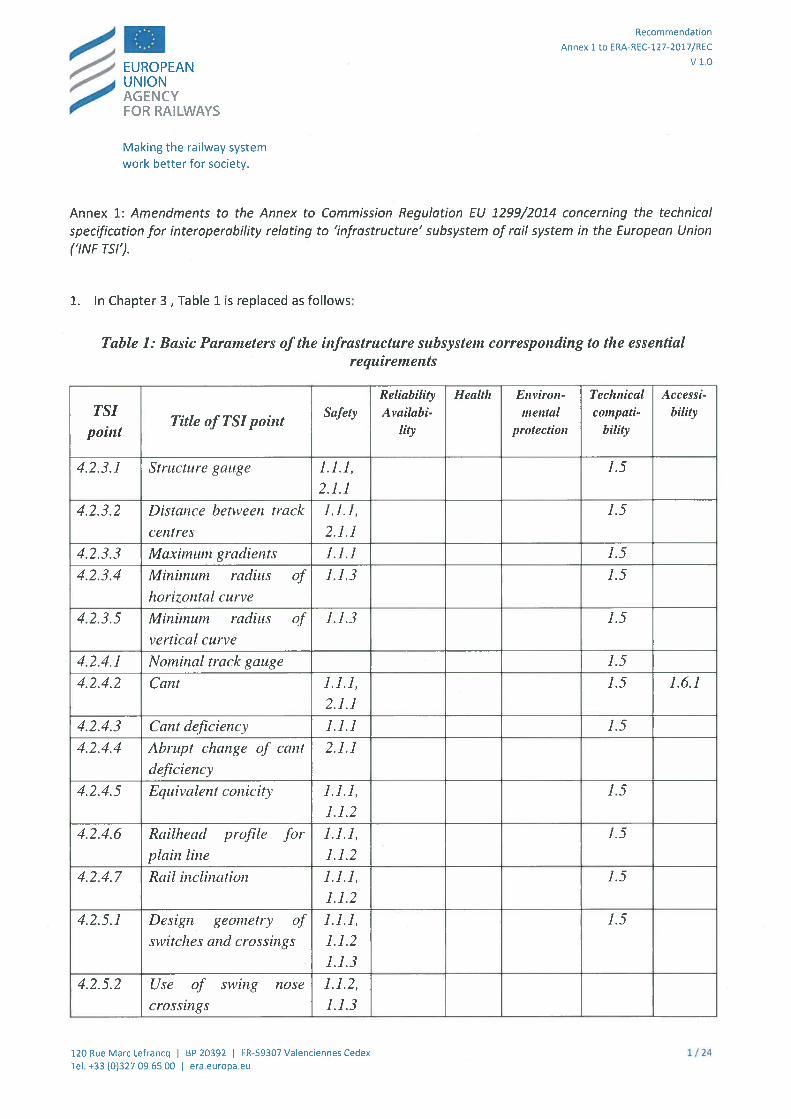
1. In Chapter 3, Table 1 is replaced as follows:
Table 1: Basic Parameters of the infrastructure subsystem corresponding to the essentialrequirements
Reliability Health Environ- Technical AccessiTSI
Title of TSI poilitSafety A vailabi- mental co,npati- bility
point lity protection bthty
4.2.3.1 Structure gauge 1.1.1, 1.52.].]
4.2.3.2 Distance between track 1.1.1, 1.5
centres 2.1.]
4.2.3.3 Maximum gradients 1.1.] 1.5
4.2.3.4 Minimum radius of 1.1.3 1.5
horizontal curve
4.2.3.5 Minimum radius of 1.1.3 1.5
vertical curve
4.2.4.] Nominal track gauge 1.5
4.2.4.2 Cant 1.].], 1.5 1.6.]2.1.]
4.2.4.3 Cant deficiency 1.1.1 1.5
4.2.4.4 Abrupt change of cant 2.1.1
deficiency
4.2.4.5 Equivalent conicily 1.1.], 1.5
1.1.2
4.2.4.6 Railheacl profile for 1.1.], 1.5
plain line 1.1.2
4.2.4.7 Rail inclination 1.1.], 1.5
1.1.2
4.2.5.] Design geometry of 1.1.], 1.5
switches and crossings 1.1.2
1.1.3
4.2.5.2 Use of swing nose 1.1.2,crossings 1.1.3
120 Rue Marc Lefrancq I BP 20392 I FR-59307 Valenciennes Cedex 1 / 24Tel. +33 (0)32709 6500 I era.europa.eu
EUROPEAN UNION AGENCY FOR RAILWAYS Recommendation
Annex 1 to ERA-REC-127-2017/REC
V 1.0
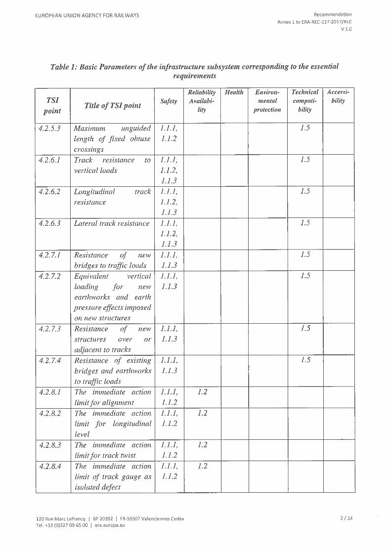
Table 1: Basic Parameters of the infrastructure subsystem corresponding to the essentialrequirements
Reliability Health Environ- Technical Accessi
TSITitle of TSI point
Safety Availabi- mental compati- bility
point lily protection bthty
4.2.5.3 Maximum unguided 1.1.1, 1.5
length of fixed obtuse 1.1.2
crossings
4.2.6.1 Track resistance to 1.1.1, 1.5
vertical loads 1.1.2,1.1.3
4.2.6.2 Longitudinal track 1.1.1, 1.5
resistance 1.1.2,1.1.3
4.2.6.3 Lateral track resistance 1.1.1, 1.5
1.1.2,1.1.3
4.2.7.1 Resistance of new 1.1.1, 1.5
bridges to traffic loads 1.1.3
4.2.7.2 Equivalent vertical 1.1.], 1.5
loading fir new 1.1.3
earthworks and cart/ipressure effects imposedon new structures
4.2.7.3 Resistance of new 1.1.1, 1.5
structures over or 1.1.3
adjacent to tracks
4.2.7.4 Resistance of existing 1.].], 1.5
bridges and earthworks 1.1.3
to traffic loads
4.2.8.1 The immediate action 1.1.1, 1.2
limit for alignment 1.1.2
4.2.8.2 The immediate action 1.1.1, 1.2
limit for longitudinal 1.1.2
level
4.2.8.3 The inzmediate action 1.1.], 1.2
limit for track twist 1.1.2
4.2.8.4 The immediate action 1.1.1, 1.2
limit of track gauge as 1.1.2
isolated defect
120 Rue Marc Lefrancq I BP 20392 I FR-59307 Valenciennes Cedex 2 / 24
Tel. +33 (0)32709 6500 I era.europa.eu

EUROPEAN UNION AGENCY FOR RAILWAYS Recommendation
Annex 1 to ERA-REC-127-2017/REC
V 1.0
Table 1: Basic Parameters of the infrastructure subsystem corresponding to the essentialrequirelnelzts
Reliability Health Environ- Technical AccessiTSI
Title of TSI pointSafety Availabi- mental comnpati- bility
point lity protection bthty
4.2.8.5 The immediate action 1.1.], 1.2limit for cant 1.1.2
4.2.8.6 The immediate action 1.1.1, 1.2 1.5
limit for switches and 1.1.2crossings
4.2.9.1 Usable length of 1.1.1, 1.5
plaUorms 2.1.1
4.2.9.2 Platform height 1.1.1, 1.5 1.6.1
2.1.1
4.2.9.3 Platform offset 1.1.], 1.5 1.6.1
2.1.1
4.2.9.4 Track layout alongside 1.1.1, 1.5 1.6.1
platforms 2.1.1
4.2.10.1 Maximum pressure 1.1.1, 1.5
variations in tunnels 2.1.1
4.2.10.2 Effect of cross winds 1.1.1, 1.2 1.52.1.1
4.2.10.3 Aerodynamic effect on 1.1.1 1.2 1.5
ba/lasted track
4.2.11.1 Location markers 1.1.1 1.2
4.2.11.2 Equivalent conicity in 1.1.1, 1.5
service 1.1.2
4.2.12.2 Toiletclischarge 1.1.5 1.2 1.3.1 1.5
4.2.12.3 Train external cleaning 1.2 1.5
facilities
4.2.12.4 Water restocking 1.1.5 1.2 1.3.1 1.5
4.2.12.5 Refuelling 1.1.5 1.2 1.3.1 1.5
4.2.12.6 Electric shore supply 1.1.5 1.2 1.5
4.4 Operating rules 1.2
4.5 Maintenance rim/es 1.2
4.6 Professional 1.1.5 1.2
qualifications
4.7 Health and safety 1.1.5 1.2 1.3 1.4.1
conditions
120 Rue Marc Lefrancq I BP 20392 I FR-59307 Valenciennex Cedex 3 / 24Tel. +33 (0)327 09 6500 I era.europa.eu
EUROPEAN UNION AGENCY FOR RAILWAYS Recommendation
Annex 1 to ERA-REC-127-2017/REC
v1.0
2. In point 4.2.1, note (*) of Table 3 “Performance parameters for freight traffic” is replaced as below(*) Axle load is based on design mass in working order for power heads and locomotives as defined in
point 2.1 of EN 15663:2009+AC:2010 and design mass under normal payload for other vehicles
according to point 6.3 of EN15663:2009+AC:2010.
3. In point 4.22.1 ‘List of basic parameters’, aspect H ‘Health, safety and environment’, point (c) is replaced
as below:
(c) Aerodynamic effect on ballasted track (4.2.10.3)
4. In point 4.2.6.2.2 ‘Compatibility with braking systems’, paragraph (2) is replaced as below:
(2) Pro visions for the use of eddy current braking systems on track shall be defined at operational level by
the infrastructure manager on the basis of the specific characteristics of the track, including switches
and crossings. The conditions of use of this braking system are registered in accordance with Decision
2014/880 (RINF).
5. In Point 4.2.2.1 “List of basic Parameters”, the following point is added to the aspect K. Maintenance
Rules:
(b) Maintenance plan (4.5.2).
6. In point 4.2.4.4 “Abrupt change of cant deficiency”, paragraph (4) is replaced as below:
(4) Instead of point (1), for the 1 668 mm track gauge system, the maximum design values of abrupt
change of cant deficiency shall be:
(a) 110 mm for v 115 km/h,
(b) (399-v)/2,6 [mm]for 115 km/h <v 220 km/h1
(c) 70 mm for 220 km/h <v 230 km/h,
(d) Abrupt change of cant deficiency is not allowed for speeds of more than 230 km/h.
7. In point 4.2.4.5 “Equivalent conicity”, paragraph (3) is replaced as below:
(3) Design track gauge, rail head profile and rail inclination for plain line shall be selected to
ensure that the equivalent conicity limits set out in Table 10 are not exceeded.
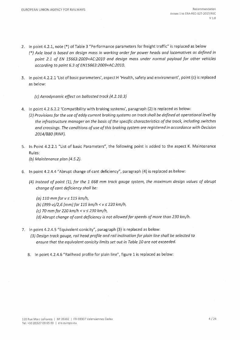
8. In point 4.2.4.6 “Railhead profile for plain line”, figure 1 is replaced as below:
120 Rue Marc Lefrancq I BP 20392 I FR-59307 Valenciennes Cedex 4 / 24
Tel. +33 (0>32709 6500 I era.europa.eu
EUROPEAN UNION AGENCY FOR RAILWAYS
(NV
Recommendation
Annex 1 to ERA-REC-127-2017/REC
V 1.0
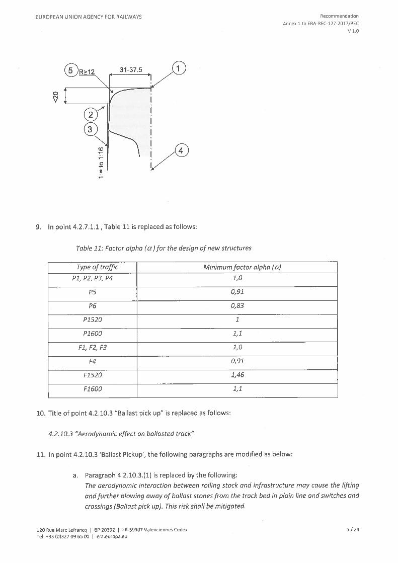
9. In point 4.2.7.1.1 , Table 11 is replaced as follows:
Table 11: Factor alpha (a)for the design of new structures
Type of traffic Minimum factor alpha (a)
P1, P2, P3, P4 1,0
P5 0,91
P6 0,83
P1520 1
P1600 1,1
Fl, F2, F3 1,0
F4 0,91
F1520 1,46
Fl 600 1,1
10. Title of point 4.2.10.3 “Ballast pick up” is replaced as follows:
4.2.10.3 “Aerodynamic effect on ballasted track”
11. In point 4.2.10.3 ‘Ballast Pickup’, the following paragraphs are modified as below:
a. Paragraph 4.2.10.3(1) is replaced by the following:
The aerodynamic interaction between rolling stock and infrastructure may cause the lifting
and further blowing away of ballast stones from the track bed in plain line and switches and
crossings (Ballast pick up). This risk shall be mitigated.
5 / 24
31-37.5
CD
0
120 Rue Marc Lefrancq I BP 20392 I FR-59307 Valenciennes CedexTel. +33 (0>327 09 6500 I era.europa.eu

EUROPEAN UNION AGENCY FOR RAILWAYS Recommendation
Annex ito ERA-REC-127-2017/REC
v1.0
b. Paragraph 4.2.10.3(2) is replaced by the following:
The requirements for the infrastructure subsystem aimed at mitigating the risk for ‘ballast
pick up’ apply only to lines intended to be operated at speed greater than 250 km/h.
c. Paragraph 4.2.10.3(3) is replaced by the following:
For lines as defined in point (2) above with intended operating speed lower than or equal to
300 km/h and equipped with mono-block sleepers and bearers, the level of the ballast
between the rails shall be lower than the upper surface of the sleepers and the bearers.
Without prejudice to Point 4.2.6, the distance between the upper surface of the sleepers and
the bearers, and the level of the ballast between rails shall be at least 3 cm.
d. Paragraph 4.2.10.3(4) is introduced and shall read as:
For speed greater than 300 km/h, the requirements of point (1) above are an open point.
12. Point 4.2.12.2 “Toilet discharge” is replaced as follows:
Fixed installations for toilet discharge shall be compatible with the characteristics of the retention toilet
system specified in the LOC & PAS TSl.
13. In point 4.2.12.4 “Water restocking”, paragraph (1) is replaced as follows:
(1) Fixed equipmentfor water restocking shall be compatible with the characteristics of the water system
specified in the LOC & PAS TSl.
14. Point 4.2.12.5 “Refuelling” is replaced as follows:
Refuelling equipment shall be compatible with the characteristics of the fuel system specified in the LOC
& PAS TSl.
15. Point 4.2.12.6 “Electrical shore supply” is replaced as follows:
Where provided, electrical shore supply shall be by means of one or more of the power supply systems
specified in the LOC & PAS TSl.
16. In point 4.3.1 “Interfaces with the rolling stock subsystem”, Table 15 “Interfaces with the rolling stock
subsystem, ‘Locomotives and Passenger Rolling Stock TSI’ “is replaced as follows:
120 Rue Marc Lefrancq I BP 20392 I FR-59307 Valenciennes Cedex 6 / 24
Tel. +33 (0)32709 6500 I era.europa.eu

EUROPEAN UNION AGENCY FOR RAILWAYS Recommendation
Annex ito ERA-REC-127-2017/REC
V 1.0
Table 15: Interfaces with the rolling stock subsystem, ‘Locomotives and PassengerRolling Stock TSI’
Interface Reference Iizfrastructure TSI Reference Locomotives aiidPassenger Rolling Stock TSJ
4.2.4.1 Nominal track gauge 4.2.3.5.2.1 Mechanical andTrack gauge4.2.5.1 Design geometry of geometrical characteristics of
switches and crossings wheelset
4.2.8.6 The immediate action 4.2.3.5.2.3 Variable gauge
tim its for switches and wheelsets
crossings
Gauge 4.2.3.1 Structure gauge 4.2.3.1. Gauging
4.2.3.2 Distance between track
centres4.2.3.5 Minimum radius ofvertical curve
4.2.9.3 Platform offset
4.2.6.] Track resistance to 4.2.2.10 Load conditions andAxle load and axle
vertical loads weighed massspacing
4.2.6.3 Lateral track resistance 4.2.3.2.1 Axle load parameter4.2.7.1 Resistance of new
bridges to traffic loads
4.2.7.2 Equivalent vertical
loadingfor new earthworks and
earth pressure effects imposed
on new structures
4.2. 7.4 Resistance of existing
bridges and earthworks to
traffic loads. . 4.2.6.1 Track resistance to 4.2.3.4.2.1 Limit values for
Running characteristicsvertical loads running safely
4.2.6.3 Lateral track resistance 4.2.3.4.2.2 Track loading limit
4.2.7.1.4 Nosing Jrces values
Ride stability 4.2.4.4 Equivalent conicity 4.2 .3 .4.3 Equivalent conicily
4.2.4.6 Railhead profile for 4.2 .3.5.2.2 Mechanical and
plain line geometrical characteristics of4.2.11.2 Equivalent conicity in wheels
service
120 Rue Marc Lefrancq I BP 20392 I FR-59307 Valenciennes Cedex 7 / 24Tel. +33 (0)327 09 6500 I era.europa.eu

EUROPEAN UNION AGENCY FOR RAILWAYS Recommendation
Annex ito ERA-REC-127-2017/REC
V 1.0
Table 15: Interfaces with the rolling stock subsystem, ‘Locomotives and Passenger
Rolling Stock TSI’
Interface Reference Infrastructure TSI Reference Locomotives and
Passenger Rolling Stock TSI
. . . 4.2.6.2 Longitudinal track 4.2.4.5 Braking performanceLongitudinal actions
resistance
4.2.7.1.5 Actions due to
traction and braking
(longitudinal_loads)
. . . 4.2.3.4 Minimum radius of’ 4.2.3.6 Minimum curve radiusMmnimuni horizontal
. horizontal curve Annex A, A.] Bifferscurve radius
. . 4.2.4.3 Cant deficiency 4.2.3.4.2. Running dynamicRunning dynamic
. behaviourbehaviour
. . 4.2.6.2 Longitudinal track 4.2.4.5 Braking peiformanceMaximum deceleration
resistance
4.2. 7.1.5 Actions due to
traction and braking
. 4.2.3.2 Distance between track 4.2.6.2.1 Slipstream effects onAerodynamic effect
centres passengers on platforms and
4.2.7.3 Resistance of new on trackside workers
structures over or adjacent to 4.2.6.2.2 Head pressure pulse
tracks 4.2.6.2.3 Maximum pressure
4.2.10.] Maximum pressure variations in tunnels
variations in tunnels
4.2.10.3 Aerodynamic e.fi’ct on 4.2.6.2.5 Aerodynamic effect
ballasted track on ballasted tracks
. 4.2.10.2 Effect of crossn’inds 4.2 .6.2 .4 CrosswindCrosswind
. 4.2.12.2 Toilet discharge 4.2.11.3 Toilet dischargeinstallations for
. . . 4.2.12.3 Train external systemservicing trains
cleaning facilities 4.2.] 1.2.2 Exterior cleaning
4.2.12.4 Water restocking through a washing plant
4.2.12.5 Refuelling 4.2.11.4 Water refilling
4.2.12.6 Electric shore supply equipment
4.2.11.5 intemface for water
refilling4.2.11. 7 Refuelling equipment
4.2.11.6 Special requirements
for stabling of trains
120 Rue Marc Lefrancq I BP 20392 I FR-59307 Valenciennes Cedex 8 / 24
Tel. +33 (0)32709 6500 I era.europa.eu

EUROPEAN UNION AGENCY FOR RAILWAYS Recommendation
Annex 1 to ERA-REC-127-2017/REC
v1.0
17. In point 4.3.1 “Interfaces with the rolling stock subsystem”, Table 16 “Interfaces with the rolling stock
subsystem, ‘Freight Wagons TSI’ “is replaced as follows:
Table 16: Interfaces with the rolling stock subsystem, ‘Freight Wagons TSI’
Inteiface Reference Infrastructure TSI Reference Freight wagonsTSI
Track gauge 4.2.4.1 Nominal track gauge 4.2.3.6.2 Characteristics of4.2.4.6 Railhead profile for plain
wheelsetsline
4.2.5.1 Design geometry of 4.2.3.6.3 Characteristics of
switches and crossings wheels
4.2.8.6 The immediate action
limits for switches and crossings
Gauge 4.2.3.1 Structure gauge 4.2.3.1 Gauging
4.2.3.2 Distance between track
centres
4.2.3.5 Minimum radius of vertical
curve
4.2.9.3 Platform offset
Axle load and axle spacing 4.2.6.1 Track resistance to vertical 4.2.3.2 Compatibility with load
loads carrying capacity of lines
4.2. 6.3 Lateral track resistance
4.2. 7.1 Resistance of new bridges
to traffic loads
4.2. 7.2 Equivalent vertical loading
for new earth works and earth
pressure effects imposed on new
structures
4.2.7.4 Resistance of existing
bridges and earth works to traffic
loads
Running dynamic 4.2.8 Immediate action limits on 4.2 .3 .5.2 Running dynamic
behaviour track geometry defects behaviour
Longitudinal actions 4.2.6.2 Longitudinal track 4.2 .4 .3 .2 Brake performance
resistance
4.2.7.1.5 Actions due to traction
and braking (longitudinal loads)
Minimum curve radius 4.2.3.4 Minimum radius of 4.2.2.1. Mechanical interface
horizontal curve
Vertical curve 4.2.3.5 Minimum radius of vertical 4.2.3.1 Gauging
curve
120 Rue Marc Lefrancq I BP 20392 I FR-59307 Valenciennes Cedex 9/24Tel. +33 (0)327 09 6500 I era.europa.eu

EUROPEAN UNION AGENCY FOR RAILWAYS Recommendation
Annex ito ERA-REC-127-2017/REC
V 1.0
18. In point 4.3.4, Table 19 “Interfaces with the operation and traffic management subsystem” is replaced
as follows:
Table 19 “Inteifaces with the operation and traffic inanagemelit subsystem”
Inteiface Reference Infrastructure TSI Reference Operation and
Traffic Management TSI
Ride stability 4.2.11.2 Equivalent conicity in 4.2 .3 .4 .4 Operational
service quality
Use of eddy current brakes 4.2.6.2 Longitudinal track 4.2 .2.6.2 Braking performance
resistance
Crosswinds 4.2.10.2 Effect of crosswinds 4.2.3.6.3 Contingencyarrangements
Operating rules 4.4 Operating rules 4.2.1.2.2.2 Modifications to
information contained in the
route book
4.2.3.6 Degraded operation
Staff competences 4.6 Professional competences 2.2.1 Staff and trains
19. Point 4.5.2 ‘Maintenance Plan’ is replaced by the following:
The infrastructure manager shall have a maintenance plan containing the items listed in point 4.5.1
together with at least the following:
(a) a set of values for intervention limits and alert limits,
(b) a statement about the methods, professional competences of staff and personal protective safety
equipment necessary to be used,
(c) the rules to be applied for the protection of people working on or near the track,
(d) the means used to check that in-service values are respected,
(e) the measures taken, for speed greater than 250 km/h, to mitigate the risk of ballast pick up.
20. In point 4.7” Health and safety conditions”, paragraph (1) is replaced as follows:
(1) The health and safety conditions of staff required for the operation and maintenance of the
infrastructure subsystem shall be compliant with the relevant European and national legislation.
21. In point 5.3.2 ‘The rail fastening systems’, point 2(b) is replaced as follows:
(b) the rail fastening shall resist application of 3 000 000 cycles of the typical load applied in a sharp
curve, such that the change in performance of the fastening system shall not exceed:
• 20 % in terms of clamping force,
• 25 % in terms of vertical stiffness,
• a reduction of more than 20% in terms of longitudinal restraint.
120 Rue Marc Lefrancq I BP 20392 I FR-59307 Valenciennes Cedex 10 / 24Tel. +33 (0)32709 6500 I era.europa.eu
EUROPEAN UNION AGENCY FOR RAILWAYS Recommendation
Annex 1 to ERA-REC-127-2017/REC
v1.0
The typical load shall be appropriate to:
the maximum axle load the railfastening system is designed to accommodate,
— the combination of rail, rail inclination, rail pad and type of sleepers with which the fastening
system may be used.
22. In point 6.2.4 “Particular assessment procedures for infrastructure subsystem”, the following point is
added:
6.2.4.15 ‘Assessment of compatibility with braking systems”
The assessment of the requirements laid down in point 4.2.6.2.2(2) is not required.
23. In point 6.2.5 “Technical solutions giving presumption of conformity at design stage”, the following point
is added:
6.2.5.3 ‘Assessment of aerodynamic effect on ballasted track”
(1) The demonstration of conformity of the track to the requirements to mitigate the risk of ballast
pick- up as laid down in point 4.2.10.3(1) may be done, alternatively to paragraph 4.2.10.3 (3), by
referring to an existing track design, including switches and crossings, on which rolling stock
compliant with point 7.1.1.8 of the LOC&PAS TSI is or has been in normal operation with the same
or higher speed.
(2) Points 6.2 .5.1 (2), (3), (4), (5) and (6) apply. For switches and crossings, technical characteristics as
set out in Appendix C.2 and conditions of use as set out in Appendix D.2 apply.
(3) When reference is made to Appendix D.1 and Appendix D.2, the only conditions of use to be
assessed are the maximum line speed on plain track and the maximum line speed on through route
on switches.
(4) The assessment of the requirements ofparagraph 6.2 .5.3(1) shall be based on a written declaration
of the infrastructure manager.
24. In point 7.3.3 “Substitution in the framework of maintenance”, paragraph (4) is replaced as follows:
(4) In such cases, it is noted that each of the above elements taken separately cannot ensure
compliance of the whole subsystem. The conformity of a subsystem can only be stated when all the
elements are compliant with the TSl.
25. In point 7.7.2 “Particular features on the Belgian network”, the first paragraph is replaced as follows:
For platform heights of 550 mm and 760 mm, the conventional value bqo of platform offset shall be
calculated according to the following formulas:
26.In point 7.7.11 “Particular features on the Latvian network”, paragraph (2) of point 7.7.11.1 shall be
deleted.
27.ln point 7.6 ‘Ascertain Compatibility of infrastructure and rolling stock after authorisation of rolling stock’,
point (2) is replaced as follows:
120 Rue Marc Lefrancq I BP 20392 I FR-59307 Valenciennes Cedex 11/24Tel. ÷33 (0>32709 6500 I era.europa.eu

EUROPEAN UNION AGENCY FOR RAILWAYS Recommendation
Annex 1 to ERA-REC-127-2017/REC
V 1.0
(2) The design of the TSI categories of line as defined in section 4 is generally compatible with the
operation of vehicles categorised in accordance with EN 15528:2015 at up to the maximum speed as
shown in Appendix E. However there may be a risk of excessive dynamic effects including resonance
in certain bridges which may further impact the compatibility of vehicles and infrastructure.
28. In point 7.7.8.1, the title “Platform height (4.2.9.3)” is replaced as follows:
“Platform height (4.2.9.2)”
29. In Appendix A, table 36 “Assessment of interoperability constituents for the EC declaration of
conformity” is replaced as follows:
5.3.1 The rail
5.3.1.1 Rallhead profile X n.a. X X
5.3.1.2 Rail steel X X X X
5.3.2 The railfastening systems n.a. n.a. X X
5.3.3 Track sleepers X X n.a. X
In Appendix B, Table 37 shall be complemented by adding the following row:
Characteristics to be Assembly before Particular assessmentDesign review
assessed putting into service procedures
Aerodynamic effect on 6.2.5.3xba/lasted track (4.2.10.3)
31. In Appendix B, the row in Table 37 relative to ‘Longitudinal track resistance’ shall be replaced as below:
Characteristics to be Assembly before Particular assessmentDesign review
assessed putting into service procedures
Longitudinal track 6.2.5x
resistance (4.2.6.2) 6.2 .4.15
12 / 24
Characteristics to be assessed Assessment in the following phase
Design and development phase Productionphase
Manufacturingprocess +
product test
Design review Review of Type testman ufacturin
g process
Product quality
(series)
30.
120 Rue Marc Lefrancq I BP 20392 I FR-59307 Valenciennes CedexTel. +33 (0)327 09 6500 I era.europa.eu

EUROPEAN UNION AGENCY FOR RAILWAYS Recommendation
Annex 1 to ERA-REC-127-2017/REC
v1.0
32. In Appendix C2 “Technical characteristics of switches and crossings design”, point “(c) Sleeper” is
replaced as follows:
(c) Bearer
33. In Appendix E:
second paragraph is replaced as follows:
EN line category is a function of axle load and geometrical aspects relating to the spacing of axles.
EN line categories are set out in Annex A of EN 15528:2015.
Table 38 ‘Capability requirements for structures according to traffic code’ is replaced as follows:
Table 38: EN Line Category —Associated Speed (km/h) — Passenger traffic
Passenger Carriages Locomotives and Electric or Diesel Multiple
(including Coaches, 2 4 Units Power Units andPower Heads
Traffic code Vans and Car Railcars (2) (3)
Carriers) and Light
Freight Wagons (2) (3)
P1 n.a. (11) n.a. (11) Open Point
P2 n.a. na. (11) Open Point
P3a (>160 km/h) A—200D2 — 200 (10) Open point
81 - 160
P3b ( 160 km/h) C2 — 160B1—160 D2—160
D2 - 120
P4a (>160 km/h) A—200D2 — 200 (10) Open point
B1 - 160
P4b(160 km/h) B17—160A — 160
D2-160 C28—14081 - 140
D2 (9)- 120
P5 81-120 C2-120”5 B1-120
P6 a12
P1520 Open point
P1 600 Open point
note (1) is replaced as follows:
13 / 24120 Rue Marc Lefrancq I OP 20392 I FR-59307 Valenciennes CedexTel. +33 (0)327 09 6500 I era.europa.eu

EUROPEAN UNION AGENCY FOR RAILWAYS Recommendation
Annex 1 to ERA-REC-127-2017/REC
V 1.0
(1) The indicated speed value in the table represents the maximum requirement for the line and
may be lower in accordance with the requirements in point 4.2.1(12). When checking individual
structures on the line, it is acceptable to take account of the type of vehicle and local allowed
speed.
• note (2)15 replaced as follows:
(2) Passenger Carriages (including Coaches, Vans, Car Carriers), Other Vehicles, Locomotives,
Power Heads, Diesel and Electric Multiple Units, Power Units and Railcars are defined in the LOC
& PAS TSl. Light Freight Wagons are defined as vans except that they are allowed to be conveyed
in formations which are not intended to convey passengers.
• note (10) shall be deleted;
• note (11) as follows shall be added:
(11) Taking into account the state of art of operation there is no need to define harmonized
requirements to deliver an adequate level of interoperability for this type of vehicles for P1 and
P2 traffic codes.
34. In Appendix F:
• Table 40 ‘Capability requirements for structures according to traffic code in United Kingdom of
Great Britain and Northern Ireland’ is replaced by the following:
Table 40: Route Availability number —Associated Speed (1) (miles per hour) — Passenger traffic
Passenger Carriages Locomotives and Electric or Diesel Multiple
(including Coaches, ‘2’ ‘4 Units, Power Units andPower Heads
Vans and Car RailcarsTraffic code Carriers) and Light (2) (3) (6)
Freight Wagons
(2) (3) (6)
P1 n.a. (11) n.a. Open Point
P2 n.a. (11) na. (11) Open Point
P3a (> 160 km/h) RA7 — 125 (7)
RA1 —125 RA8—1107Open point
RA2—90 RA8—100”8
RA5—125”9
P3b ( 160 km/h) RA1 —100 RA8 — 100 RA3 — 100
120 Rue Marc Lefrancq I BP 20392 FR-59307 Valenciennes Cedex 14 / 24
Tel. +33 (0)327 09 6500 I era.europa.eu

EUROPEAN UNION AGENCY FOR RAILWAYS Recommendation
Annex ito ERA-REC-127-2017/REC
V 1.0
RA2—90 RA5—100”9
P4a (> 160 km/h) RA7 — 125 (7)
RA1 —125RA7 — 100 (8) Open point
RA2—90RA4—125”9
P4b(160 km/h) RA1—100 RA7—100”8RA3—100
RA2—90 RA4—100”9
PS RA5 — 75 (8) (10)
RA1—75 RA3—75RA4— 75
(9)(10)
P6 RA1
P1600 Open point
• note (1) is replaced as follows:
(1) The indicated speed value in the table represents the maximum requirement for the line and may
be lower in accordance with the requirements in point 4.2.1(12). When checking individual
structures on the line, it is acceptable to take account of the type of vehicle and local allowed
speed.
• note (2) is replaced as follows;
(2) Passenger Carriages (including Coaches, Vans, Car Carriers), Other Vehicles, Locomotives, Power
Heads, Diesel and Electric Multiple Units, Power Units and Railcars are defined in the LOC & PAS
T5I. Light Freight Wagons are defined as vans except that they are allowed to be conveyed in
formations which are not intended to convey passengers.
• Note (11) shall be added as follows:
(11) Taking into account the state of art of operation there is no need to define harmonized
requirements to deliver an adequate level of interoperability for this type of vehicles for P1 and P2
traffic codes.
35. In Appendix K, fourth paragraph: ‘It is anticipated that the next revision of EN15528+A1:2012 will specify
that these mass definitions shall be used when checking the compatibility of infrastructure and rolling
stock.’ shall be deleted;
36. Appendix L ‘Definition of EN line category o12 for traffic code P6’ shall be deleted;
37. In Appendix P, point P3 “Vertical lowering”, the second paragraph is modified as follows (normal font):
120 Rue Marc Lefrancq I BP 20392 I FR-59307 Valenciennes Cedex iS / 24Tel. +33 (0)327 09 6500 I era.europa.eu
EUROPEAN UNION AGENCY FOR RAILWAYS Recommendation
Annex ito ERA-REC-127-2017/REC
v1.0
The vertical curve radius Rv is limited to 50Gm. Heights not exceeding 80 mm shall be considered as
zero within a radius Rv between 500 m and 625 m.
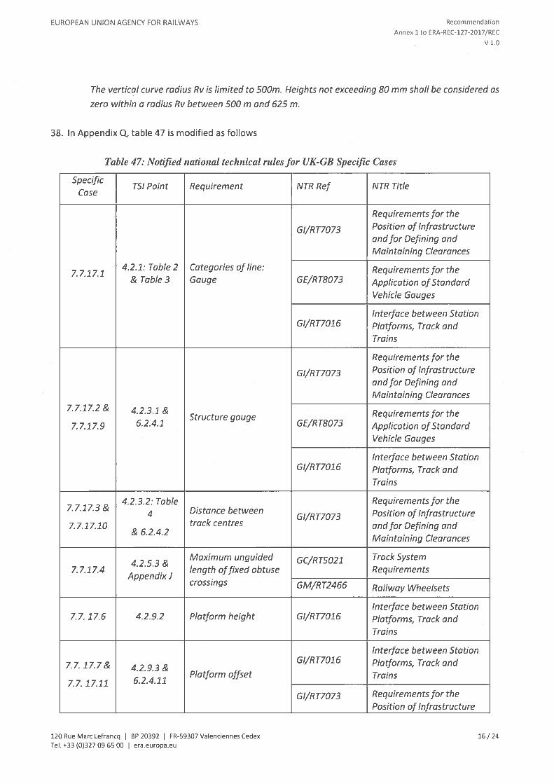
38. In Appendix 0, table 47 is modified as follows
Table 47: Notified national technical rules for UK-GB Specific Cases
SpecificTSI Point Requirement NTR Ref NTR Title
Case
Requirements for the
Gl/RT7073 Position of Infrastructureandfor Defining andMaintaining Clearances
4.2.1: Table 2 Categories of line: Requirements for the7.7.17.1& Table 3 Gauge GE/RT8073 Application of Standard
Vehicle Gauges
Interface between StationGI/RT7016 Platforms, Track and
Trains
Requirements for the
GI/RT7073 Position of Infrastructureand for Defining andMaintaining Clearances
7.7.1 7.2 & 4.2.3.1 & Requirements for theStructure gauge6.2.4.1 GE/RT8073 Application of Standard7.7.17.9
Vehicle Gauges
Interface between StationGI/RT7016 Platforms, Track and
Trains
4.2.3.2: Table Requirements for the7.7.1 7.3 & Distance between‘ Gl/RT7073 Position of Infrastructure7. 7.1 7.10 track centres and for Defining and
& 6.2.4.2Maintaining Clearances
Maximum unguided GC/RTS021 Track System4.2.5.3 &
7.7.1 7.4 length offixed obtuse RequirementsAppendixi
crossings GM/RT2466 Railway Wheelsets
Interface between Station7.7. 17.6 4.2.9.2 Platform height Gl/RT7016 Platforms, Track and
Trains
Interface between StationGl/RT7016 Platforms, Track and7.7.17.7& 4.2.9.3&
Platform offset Trains7.7. 17.11 6.2 .4.11
Gl/RT7073 Requirements for thePosition of Infrastructure
120 Rue Marc Lefrancq I BP 20392 I FR-59307 Valenciennes Cedex 16 / 24Tel. +33 (0)32709 6500 I era.europa.eu

EUROPEAN UNION AGENCY FOR RAILWAYS Recommendation
Annex ito ERA-REC-127-2017/REC
V 1.0
andfor Defining andMaintaining Clearances
39. Appendix R ‘List of open points’ is replaced as follows:
List of open points
(1) Immediate action limit5forisolated defects in alignmentforspeeds of more than 300 km/h (4.2.8.1).
(2) Immediate action limits for isolated defects in longitudinal level for speeds of more than 300 km/h(4.2.8.2).
(3) The minimum allowed value of distance between track centres for the uniform structure gauge IRL3is an open point (7. 7.18.2).
(4) EN Line Category —Associated Speed [km/h]for Traffic codes P1 (multiple units), P2 (multiple units),P3a (multiple units), P4a (multiple units), P1520 (all vehicles), P1600 (all vehicles), F1520 (allvehicles) and F1600 (all vehicles) in Appendix E, Tables 38 and 39.
(5) Route Availability Number —Associated Speed [miles/h] for Traffic codes P1 (multiple units), P2(multiple units), P3a (multiple units), P4a (multiple units), P1600 (all vehicles) and F1600 (allvehicles) in Appendix F. Tables 40 and 41.
(6) Rules and drawings related to gauges IRL1, IRL2 and IRL3 are an open point (Appendix 0).
(7) The requirements for mitigating the risk for ballast pick up for speed greater than 300 km/h.
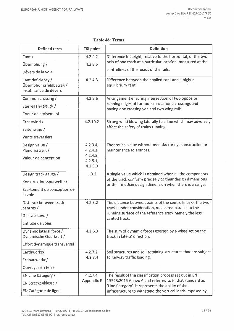
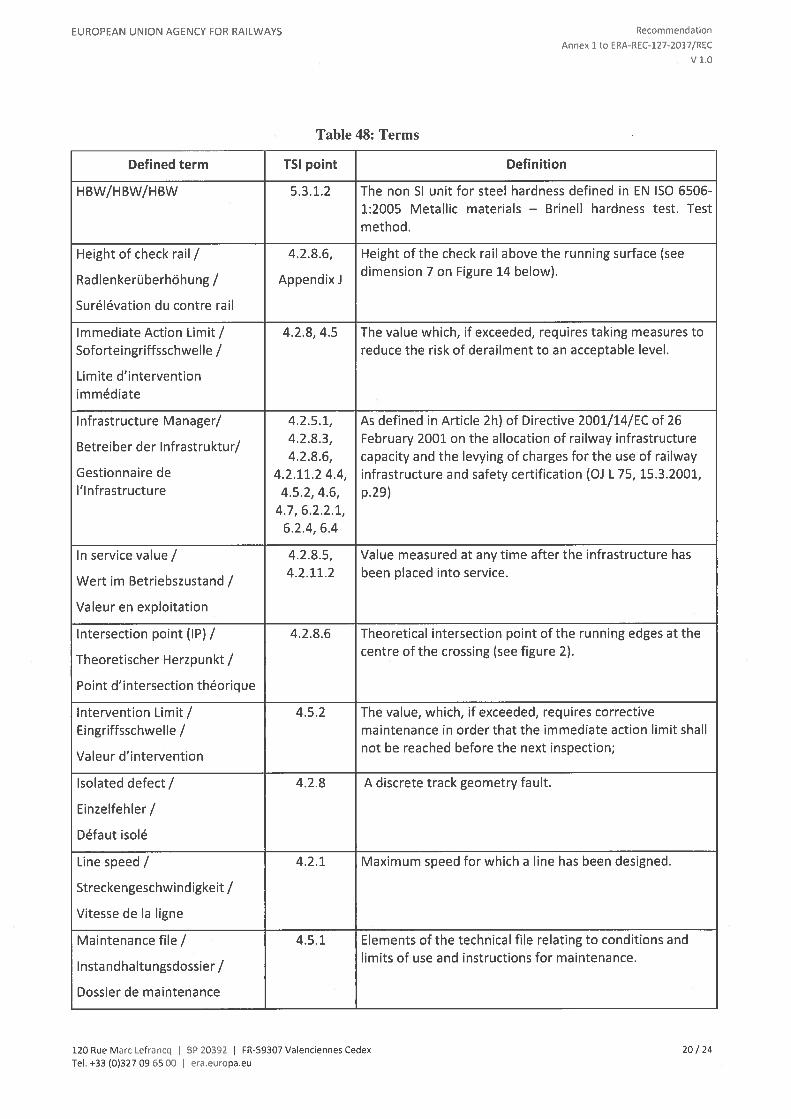
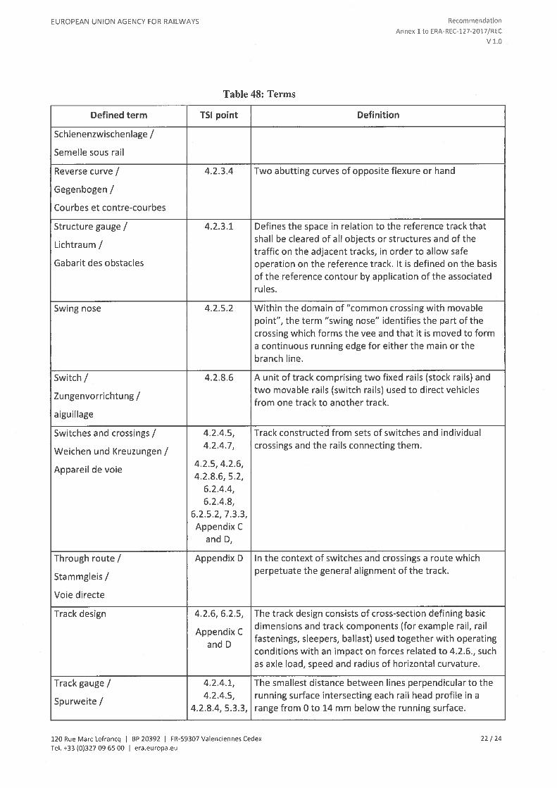
40. In Appendix S “Glossary”, Table 48 is replaced by the following:
Table 48: Terms
Defined term TSI point Definition
Actual point (RP) / 4.2.8.6 Physical end of a crossing vee. See Figure 2, which shows. the relationship between the actual point (RP) and the
Praktischer Herzpunkt /intersection point (IP).
Pointe de coeur
Alert limit / 4.5.2 Refers to the value which, if exceeded, requires that the.. track geometry condition is analysed and considered in the
Auslosewert/regularly planned maintenance operations.
Limite d’alerte
Axle load! 4.2.1, 4.2.6.1 Sum of the static vertical wheel forces exerted on the trackthrough a wheelset or a pair of independent wheels
Achsfahrmasse/ . .
divided by acceleration of gravity.Charge a l’essieu
Braking systems independent 4.2.6.2.2 “Braking systems independent of wheel — rail adhesionof wheel-rail adhesion conditions” refers to all brake systems of the rolling stockconditions” capable to develop a brake force applied to the rails
independently of the wheel — rail adhesion conditions (e.g.magnetic braking systems and eddy current brakingsystems)
120 Rue Marc Lefrancq I BP 20392 I FR-59307 Vaienciennes Cedex 17 / 24Tel. +33 (0)327 09 6500 I era.europa.eu
EUROPEAN UNION AGENCY FOR RAILWAYS Recommendation
Annex ito ERA-REC-127-2017/REC
v1.o
Table 48: Terms
Defined term TSI point Definition
Cant / 4.2.4.2 Difference in height, relative to the horizontal, of the two.. rails of one track at a particular location, measured at theUberhohung / 4.2.8.5
. centrelines of the heads of the rails.Devers de Ia voie
Cant deficiency! 4.2.4.3 Difference between the applied cant and a higherUberhohungsfehlbetrag / equilibrium cant.Insuffisance de devers
Common crossing / 4.2.8.6 Arrangement ensuring intersection of two opposite.. running edges of turnouts or diamond crossings and
Starres Herzstuck/ .
having one crossing vee and two wing rails.Coeur de croisement
Crosswind / 4.2.10.2 Strong wind blowing laterally to a line which may adversely. . affect the safety of trains running.
Seitenwind/
Vents traversiers
Design value! 4.2.3.4, Theoretical value without manufacturing, construction orPlanungswert/ 4.2.4.2, maintenance tolerances.
. 4.2.4.5,Valeur de conception
4.2.5.1,4.2.5.3
Design track gauge / 5.3.3 A single value which is obtained when all the components. of the track conform precisely to their design dimensions
Konstruktionsspurweite/ . .
or their median design dimension when there is a range.Ecartement de conception deIa voie
Distance between track 4.2.3.2 The distance between points of the centre lines of the twocentres / tracks under consideration, measured parallel to the
. running surface of the reference track namely the lessGleisabstand!
canted track.Entraxe de voies
Dynamic lateral force / 4.2.6.3 The sum of dynamic forces exerted by a wheelset on theDynamische Querkraft/ track in lateral direction.
Effort dynamique transversal
Earthworks/ 4.2.7.2, Soil structures and soil-retaining structures that are subject4.2.7.4 to railway traffic loading.
Erdbauwerke/
Ouvrages en terre
EN Line Category / 4.2.7.4, The result of the classification process set out in ENAppendix E 15528:2015 Annex A and referred to in that standard as
EN Streckenklasse! . .
‘Line Category’. It represents the ability of theEN Catégorie de ligne infrastructure to withstand the vertical loads imposed by
120 Rue Marc Lefrancq I BP 20392 I FR-59307 Vaienciennes Cedex 18 / 24
Tel. +33 (0)32709 6500 I era.europa.eu

EUROPEAN UNION AGENCY FOR RAILWAYS Recommendation
Annex 1 to ERA-REC-127-2017/REC
V 1.0
Table 48: Terms
Defined term TSI point Definition
vehicles on the line or section of line for regular (“normal”)service.
Equivalent conicity / 4.2.4.5, The tangent of the cone angle of a wheelset with conedAquivalente Konizität / 4.2.11.2 wheels whose lateral movement has the same kinematicConicité équivalente wavelength as the given wheelset on straight track and
large-radius curves.
Fixed nose protection / 4.2.5.3, Dimension between the crossing nose and check rail (see. . Appendix J dimension No. 2 on Figure 10 below).
Leitweite /Cote de protection de pointe
Flangeway depth / 4.2.8.6. Dimension between the running surface and the bottom of. . flangeway (see dimension No. 6 on Figure 10 below).
Rillentiefe /Profondeur d’ornière
Flangeway width / 4.2.8.6. Dimension between a running rail and an adjacent check. . or wing rail (see dimension No. 5 on Figure 10 below).
Rillenweite /Largeur d’ornière
Free wheel passage at check 4.2.8.6. Dimension between the working face of the crossing checkrail/wing rail entry/ rail or wing rail and the gauge face of the running railFreier Raddurchlauf im opposite across the gauge measured at entry to check railRadlenker-Einlauf or wing rail respectively./Flugelschienen-Einlauf/ Côte .
. ... (see dimensions No.4 on Figure 10 below). The entry to the
d equilibrage du contre-rail . . . . .
check rail or wing rail is the point at which the wheel isallowed to contact the check rail or wing rail.
Free wheel passage at crossing 4.2.8.6. Dimension between the working face of the crossing wingnose/ rail and check rail opposite across the gauge (see
. . dimension No.3 on Figure 10 below).Freier Raddurchlauf imBereich der Herzspitze/
Cote de libre passage dans lecroisement
Free wheel passage in 4.2.8.6. Dimension from the gauge face of one switch rail to theswitches/ Freier Raddurchlauf back edge of the opposite switch rail (see dimension No.1im Bereich der Zungen- on Figure 10 below).vorrichtung / Côte de librepassage de l’aiguillage
Gauge / 4.2.1, Set of rules including a reference contour and its. . associated calculation rules allowing definition of the outerBegrenzungslinie / 4.2.3.1 . .
dimensions of the vehicle and the space to be cleared byGabarit the infrastructure.
120 Rue Marc Lefrancq I BP 20392 I FR-59307 Valenciennes Cedex 19 / 24Tel. +33 (0)327 09 6500 I era.europa.eu
EUROPEAN UNION AGENCY FOR RAILWAYS Recommendation
Annex ito ERA-REC-127-2017/REC
V 1.0
Table 48: Terms
Defined term TSI point Definition
HBW/HBW/HBW 5.3.1.2 The non SI unit for steel hardness defined in EN ISO 6506-1:2005 Metallic materials — Brinell hardness test. Testmethod.
Height of check rail! 4.2.8.6, Height of the check rail above the running surface (see.. .. dimension 7 on Figure 14 below).
Radlenkeruberhohung/ Appendixi
Surélévation du contre rail
Immediate Action Limit! 4.2.8, 4.5 The value which, if exceeded, requires taking measures toSoforteingriffsschwelle/ reduce the risk of derailment to an acceptable level.
Limite d’interventionimmediate
Infrastructure Manager! 4.2.5.1, As defined in Article 2h) of Directive 2001/14/EC of 26. 4.2.8.3 February 2001 on the allocation of railway infrastructure
Betreiber der lnfrastruktur/ .
4.2.8.6, capacity and the levying of charges for the use of railwayGestionnaire de 4.2.11.2 4.4, infrastructure and safety certification (Di L 75, 15.3.2001,l’lnfrastructure 4.5.2, 4.6, p.29)
4.7, 6.2.2.1,6.2.4, 6.4
In service value! 4.2.8.5, Value measured at any time after the infrastructure has. 4.2.11.2 been placed into service.
Wert rn Betriebszustand!
Valeur en exploitation
Intersection point (IP)! 4.2.8.6 Theoretical intersection point of the running edges at the. centre of the crossing (see figure 2).
Theoretischer Herzpunkt!
Point d’intersection théorique
Intervention Limit! 4.5.2 The value, which, if exceeded, requires correctiveEingriffsschwelle/ maintenance in order that the immediate action limit shall
,.. not be reached before the next inspection;
Valeur d intervention
Isolated defect! 4.2.8 A discrete track geometry fault.
Einzelfehler!
Défaut isolé
Line speed! 4.2.1 Maximum speed for which a line has been designed.
Streckengeschwindigkeit!
Vitesse de Ia ligne
Maintenance file! 4.5.1 Elements of the technical file relating to conditions and. limits of use and instructions for maintenance.
Instandhaltungsdossier!
Dossier de maintenance
120 Rue Marc Lefrancq I BP 20392 I FR-59307 Vaienciennes Cedex 20 / 24Tei. +33 (0)327 09 6500 I era.europa.eu

EUROPEAN UNION AGENCY FOR RAILWAYS Recommendation
Annex 1 to ERA-REC-127-2017/REC
V 1.0
Table 48: Terms
Defined term TSI point Definition
Maintenance plan / 4.5.2 A series of documents setting out the infrastructuremaintenance procedures adopted by an Infrastructure
Instandhaltungsplan /Manager.
Plan de maintenance
Multi-rail track! 4.2.2.2 Track with more than two rails, where at least two pairs of. . respective rails are designed to be operated as separate
Mehrschienengleis/ . .
single tracks, with or without different track gauges.Voie a multi écartement
Nominal track gauge! 4.2.4.1 A single value which identifies the track gauge but mayNennspurweite / differ from the design track gauge.
Ecartement nominal de Ia voie
Normal service / 4.2.2.2 The railway operating to a planned timetable service.
Regelbetrieb! 4.2.9
Service régulier
Passive provision! 4.2.9 Provision for the future construction of a physical
extension
to a structure (for example: increased platformVorsorge fur kunftige
I thErweiterungen! Reservation
eng
pour extension future
Performance Parameter! 4.2.1 Parameter describing a TSI Category of Line used as the. basis for the design of infrastructure subsystem elements
Leistungskennwert! . .
and as the indication of the performance level of a line.Paramètre de performance
Plain line! 4.2.4.5 Section of track without switches and crossings.
Freie Strecke! 4.2.4.6
Voie courante 4.2.4.7
Point retraction! 4.2.8.6 The reference line in a fixed common crossing can deviate. . from the theoretical reference line. From a certain
Spitzenbeihobelung/ . .
distance to the crossing point, the reference line of the veeDénivelation de Ia pointe de can, depending on the design, be retracted from thiscur theoretical line away from the wheel flange in order to
avoid contact between both elements. This situation isdescribed in Figure 2.
Rail inclination / 4.2.4.5 An angle defining the inclination of the head of a rail whenSchienenneigung!
4 2 4 7installed in the track relative to the plane of the rails
. . . . (running surface), equal to the angle between the axis ofInclinaison du rail . .
symmetry of the rail (or of an equivalent symmetrical railhaving the same rail head profile) and the perpendicular tothe plane of the rails.
Rail pad! 5.3.2 A resilient layer fitted between a rail and the supportingsleeper or baseplate.
120 Rue Marc Lefrancq I BP 20392 I FR-59307 Vaienciennes Cedex 21/24Tel. +33 (0>32709 6500 I era.europa.eu
EUROPEAN UNION AGENCY FOR RAILWAYS Recommendation
Annex ito ERA-REC-127-2017/REC
V 1.0
Table 48: Terms
Defined term TSI point Definition
Schienenzwischenlage /Semelle sous rail
Reverse curve / 4.2.3.4 Two abutting curves of opposite flexure or hand
Gegenbogen ICourbes et contre-courbes
Structure gauge / 4.2.3.1 Defines the space in relation to the reference track that. shall be cleared of all objects or structures and of the
Lichtraum /traffic on the adjacent tracks, in order to allow safe
Gabarit des obstacles operation on the reference track. It is defined on the basisof the reference contour by application of the associatedrules.
Swing nose 4.2.5.2 Within the domain of “common crossing with movablepoint”, the term “swing nose” identifies the part of thecrossing which forms the vee and that it is moved to forma continuous running edge for either the main or thebranch line.
Switch / 4.2.8.6 A unit of track comprising two fixed rails (stock rails) and. two movable rails (switch rails) used to direct vehicles
Zungenvorrichtung / from one track to another track.aiguillage
Switches and crossings / 4.2.4.5, Track constructed from sets of switches and individual. 4.2.4.7, crossings and the rails connecting them.
Weichen und Kreuzungen /. . 4.2.5, 4.2.6,
Appareil de voie4.2.8.6, 5.2,
6.2.4.4,6.2.4.8,
6.2.5.2, 7.3.3,Appendix C
and D,
Through route / Appendix D In the context of switches and crossings a route which. perpetuate the general alignment of the track.
Stammgleis /Voie directe
Track design 4.2.6, 6.2.5, The track design consists of cross-section defining basic. dimensions and track components (for example rail rail
Appendix C .
and Dfastenings, sleepers, ballast) used together with operatingconditions with an impact on forces related to 4.2.6., suchas axle load, speed and radius of horizontal curvature.
Track gauge / 4.2.4.1, The smallest distance between lines perpendicular to the. 4.2.4.5, running surface intersecting each rail head profile in a
Spurweite/4.2.8.4, 5.3.3, range from 0 to 14 mm below the running surface.
120 Rue Marc Lefrancq I BP 20392 I FR-59307 Vaienciennes Cedex 22 / 24Tel. +33 (0)32709 6500 I era.europa.eu

EUROPEAN UNION AGENCY FOR RAILWAYS Recommendation
Annex 1 to ERA-REC-127-2017/REC
v1.0
Table 48: Terms
Defined term TSI point Definition
Ecartement de Ia voie 6.1.5.2,6.2.4.3,
Appendix H
Track twist! 4.2.7.1.6 Track twist is defined as the algebraic difference between. . 4.2.8.3 two cross levels taken at a defined distance apart usually
Gleisverwindung / 6.2.4.9, expressed as a gradient between the two points at whichGauche the cross level is measured.
Train length! 4.2.1 The length of a train, which can run on a certain line in.. normal operation.
Zugla nge/
Longueur du train
Unguided length of an obtuse 4.2.5.3, Portion of obtuse crossing where there is no guidance ofcrossing! Appendix J the wheel described as “unguided distance” in EN 13232-
.. 3:2003.Fuhrungslose Stelle/
Lacune dans Ia traversée
Usable length of a platform! 4.2.1, 4.2.9.1 The maximum continuous length of that part of platform inBahnsteignutzlange/ front of which a train is intended to remain stationary in
. . normal operating conditions for passengers to board andLongueur utile de quai .
. alight from the train, making appropriate allowance forstopping tolerances.
Normal operating conditions means that railway isoperating in a non-degraded mode (e.g. rail adhesion isnormal, signals are working, everything is working asplanned).
41. In Appendix T ‘List of referenced standards’, index n.4 of Table 49 is replaced as follows:
4 EN 13848-1 Track geometry quality 2003 The immediate action limit for track twist—Partl: (4.2.8.3)Characterisation oftrack geometry(with AmendmentAl :2008)
42. In AppendixT ‘List of referenced standards’, index n.9 of Table 49 is replaced as follows:
9 EN 15528 Railway applications — 2015 Ascertain compatibility of infrastructureLine categories for and rolling stock after authorisation ofmanaging the interface rolling stock (7.6), Capabilitybetween load limits of requirements for structures according to
traffic code (Appendix E), Basis ofminimum requirements for structures for
120 Rue Marc Lefrancq I BP 20392 I FR-59307 Vaienciennes Cedex 23 / 24
Tel. +33 (0)32709 65 00 I era.europa.eu

EUROPEAN UNION AGENCY FOR RAILWAYS Recommendation
Annex 1 to ERA-REC-127-2017/REC
V 1.0
vehicles and passenger coaches and multiple unitsinfrastructure (Appendix K)
120 Rue Marc Lefrancq BP 20392 I FR-59307 Valenciennes Cedex 24 I 24Tel. +33 (0)32709 6500 I era.europa.eu