recommendations for enabling manual component level ... · level electronic repair for future space...
TRANSCRIPT
Peter M. StrukGlenn Research Center, Cleveland, Ohio
John W. EastonNational Center for Space Exploration Research, Glenn Research Center, Cleveland, Ohio
Gregory P. FunkZIN Technologies, Cleveland, Ohio
Gary S. Latta, Andrew W. Ganster, and Brett E. EstesUnited States Navy, Naval Sea Systems Command, Crane, Indiana
Recommendations for Enabling Manual Component Level Electronic Repair for Future Space Missions
NASA/TM—2011-216933
January 2011
https://ntrs.nasa.gov/search.jsp?R=20110006369 2020-03-14T08:14:00+00:00Z
NASA STI Program . . . in Profi le
Since its founding, NASA has been dedicated to the advancement of aeronautics and space science. The NASA Scientifi c and Technical Information (STI) program plays a key part in helping NASA maintain this important role.
The NASA STI Program operates under the auspices of the Agency Chief Information Offi cer. It collects, organizes, provides for archiving, and disseminates NASA’s STI. The NASA STI program provides access to the NASA Aeronautics and Space Database and its public interface, the NASA Technical Reports Server, thus providing one of the largest collections of aeronautical and space science STI in the world. Results are published in both non-NASA channels and by NASA in the NASA STI Report Series, which includes the following report types: • TECHNICAL PUBLICATION. Reports of
completed research or a major signifi cant phase of research that present the results of NASA programs and include extensive data or theoretical analysis. Includes compilations of signifi cant scientifi c and technical data and information deemed to be of continuing reference value. NASA counterpart of peer-reviewed formal professional papers but has less stringent limitations on manuscript length and extent of graphic presentations.
• TECHNICAL MEMORANDUM. Scientifi c
and technical fi ndings that are preliminary or of specialized interest, e.g., quick release reports, working papers, and bibliographies that contain minimal annotation. Does not contain extensive analysis.
• CONTRACTOR REPORT. Scientifi c and
technical fi ndings by NASA-sponsored contractors and grantees.
• CONFERENCE PUBLICATION. Collected papers from scientifi c and technical conferences, symposia, seminars, or other meetings sponsored or cosponsored by NASA.
• SPECIAL PUBLICATION. Scientifi c,
technical, or historical information from NASA programs, projects, and missions, often concerned with subjects having substantial public interest.
• TECHNICAL TRANSLATION. English-
language translations of foreign scientifi c and technical material pertinent to NASA’s mission.
Specialized services also include creating custom thesauri, building customized databases, organizing and publishing research results.
For more information about the NASA STI program, see the following:
• Access the NASA STI program home page at http://www.sti.nasa.gov
• E-mail your question via the Internet to help@
sti.nasa.gov • Fax your question to the NASA STI Help Desk
at 443–757–5803 • Telephone the NASA STI Help Desk at 443–757–5802 • Write to:
NASA Center for AeroSpace Information (CASI) 7115 Standard Drive Hanover, MD 21076–1320

Peter M. StrukGlenn Research Center, Cleveland, Ohio
John W. EastonNational Center for Space Exploration Research, Glenn Research Center, Cleveland, Ohio
Gregory P. FunkZIN Technologies, Cleveland, Ohio
Gary S. Latta, Andrew W. Ganster, and Brett E. EstesUnited States Navy, Naval Sea Systems Command, Crane, Indiana
Recommendations for Enabling Manual Component Level Electronic Repair for Future Space Missions
NASA/TM—2011-216933
January 2011
National Aeronautics andSpace Administration
Glenn Research CenterCleveland, Ohio 44135
Acknowledgments
The work was sponsored by the Supportability Project of NASA’s Exploration Technology Development Program.
Available from
NASA Center for Aerospace Information7115 Standard DriveHanover, MD 21076–1320
National Technical Information Service5301 Shawnee Road
Alexandria, VA 22312
Available electronically at http://gltrs.grc.nasa.gov
Trade names and trademarks are used in this report for identifi cation only. Their usage does not constitute an offi cial endorsement, either expressed or implied, by the National Aeronautics and
Space Administration.
Level of Review: This material has been technically reviewed by technical management.

NASA/TM—2011-216933 iii
Executive Summary Long duration missions to the Moon and Mars pose a number of challenges to mission designers,
controllers, and the crews. Among these challenges are planning for corrective maintenance actions which often require a repair. Current repair strategies on the International Space Station (ISS) rely primarily on the use of Orbital Replacement Units (ORUs), where a faulty unit is replaced with a spare, and the faulty unit typically returns to Earth for analysis and possible repair. The strategy of replace to repair has posed challenges even for the ISS program. Repairing faulty hardware at lower levels such as the component level can help maintain system availability in situations where no spares exist and potentially reduce logistic resupply mass.
This report provides recommendations to help enable manual replacement of electronics at the component-level for future manned space missions. The recommendations include hardware, tools, containment options, and crew training. The recommendations are based on the work of the Component Level Electronics Assembly Repair (CLEAR) task of the Exploration Technology Development Program from 2006 to 2009. The recommendations are derived based on the experience of two experiments conducted by the CLEAR team aboard the International Space Station as well as a group of experienced Miniature/Microminiature (2M) electronics repair technicians and instructors from the U.S. Navy 2M Project Office. The emphasis of the recommendations is the physical repair. Fault diagnostics and post-repair functional test are discussed in other CLEAR reports.

NASA/TM—2011-216933 iv
NASA/TM—2011-216933 v
Contents Executive Summary ..................................................................................................................................... iii 1.0 Introduction .......................................................................................................................................... 1 2.0 Background—Current ISS Repair Methods and Capabilities .............................................................. 2 3.0 Recommendations for Future Space Missions ..................................................................................... 5
3.1 Manual versus Semi-Automated Repair ..................................................................................... 5 3.2 Hardware and Tool Recommendations ....................................................................................... 6
3.2.1 Soldering Equipment ................................................................................................... 10 3.2.2 Hand and Dental Tools................................................................................................ 10 3.2.3 Materials and Supplies ................................................................................................ 11 3.2.4 Specialty Tools and Repair Kits .................................................................................. 12 3.2.5 Containment Enclosure and Visual Aids .................................................................... 12 3.2.6 Diagnostics to Support Manual Repair ....................................................................... 13 3.2.7 Component Repair Experiment-1 Tool Kit ................................................................. 13
3.3 Crew Training ........................................................................................................................... 14 3.3.1 Preflight Training ........................................................................................................ 15 3.3.2 In Flight Training and Practice ................................................................................... 16
3.4 Design and Manufacturing Recommendations for Electronics Assemblies ............................. 16 3.4.1 Accessibility ................................................................................................................ 17 3.4.2 Component Layout ...................................................................................................... 17 3.4.3 Conformal Coating ...................................................................................................... 17
4.0 Summary ............................................................................................................................................ 19 Appendix A.—List of Acronyms ................................................................................................................ 21 Appendix B.—Detailed Crew Training Syllabus Developed by the U.S. Navy ......................................... 23 References ................................................................................................................................................... 32

NASA/TM—2011-216933 vi
NASA/TM—2011-216933 1
Recommendations for Enabling Manual Component Level Electronic Repair for Future Space Missions
Peter M. Struk
National Aeronautics and Space Administration Glenn Research Center Cleveland, Ohio 44135
John W. Easton
National Center for Space Exploration Research Glenn Research Center Cleveland, Ohio 44135
Gregory P. Funk
ZIN Technologies Cleveland, Ohio 44135
Gary S. Latta, Andrew W. Ganster, and Brett E. Estes
United States Navy Naval Sea Systems Command
Crane, Indiana 47522
1.0 Introduction Long duration missions to the Moon and Mars pose a number of challenges to mission designers,
controllers, and the crews. Among these challenges are planning for corrective maintenance actions which often require a repair. Current repair strategies on the International Space Station (ISS) rely primarily on the use of Orbital Replacement Units (ORUs), where a faulty unit is replaced with a spare, and the faulty unit typically returns to Earth for analysis and possible repair. This relies on storing spare ORUs in orbit, or launching the spare at the earliest opportunity and the crew relying on a backup or operating at a reduced capacity until the spare arrives. While appropriate for the ISS, this strategy of replace to repair poses significant challenges for outposts on the Moon and for Martian missions (including the long-duration flight to Mars). These future missions are challenged with storage space and launch mass constraints which allow only limited spares. Furthermore, the distance from Earth to the Moon and Mars makes “on demand” resupply significantly more difficult.
The strategy of replace to repair has posed challenges even for the ISS program. The grounding of the Space Shuttle fleet following the loss of Space Shuttle Columbia had resulted in a delay in the assembly of ISS and greatly reduced the cargo mass available for resupply and research. Furthermore, the loss of down mass has impacted the program’s ability to return failed hardware for analysis and repair. Fortunately, the ISS program was able to rely on international partner vehicles to allow continued crewed operations of the ISS (Ref. 1). This situation will, once again, occur when the Space Shuttle fleet is retired after 2010.
One corrective maintenance action is recovering from electronics failures. These failures may occur for a number of reasons such as damage caused by the environment, faults and upsets in, or a part of the system outliving its useful lifetime. Generally, the damage is limited to a small number of associated systems of individual components on a circuit board or assembly, such as resistors, capacitors, diodes, or an integrated circuit (IC) chips. Often, isolating the failure to the component level has not been possible aboard the ISS due to limited equipment and crew time. However, understanding the root-cause failure usually requires isolating a fault to the component level.
Troubleshooting of electronic faults will often follow multiple steps. Initially, ground controllers would use the vehicles health management system along with built-in-test (BIT) capabilities. This type of troubleshooting can be expected to isolate the fault to the ORU level. Additional fault isolation or ambiguity
NASA/TM—2011-216933 2
resolution (i.e., more than one possible faulty ORU) would require a crewmember to go the potential faulty hardware. Here, the crewmember would use diagnostic tools as well as mechanical tools to allow access and potentially remove and replace the faulty hardware at an ORU level. For future outpost missions, the faulty ORU will not likely return to Earth due to limited return mass capabilities. Therefore, root-cause fault assessment will require a crewmember to disassemble the ORUs to lower-levels most likely at an area dedicated for maintenance. Furthermore, repair at these lower levels can maintain system availability in situations where no spares exist and potentially reduce logistic resupply mass.
The crew will be required to perform fault isolation and repair using the limited tools they have available. Therefore, it is imperative that the tools be selected appropriately for the mission. From 2006 to 2009, the Component Level Electronics Assembly Repair (CLEAR) task1 investigated how to enable a component-level electronics repair capability on future missions. Such repairs will require new diagnostic and repair tools suited for the environments and resource constraints found in these future missions. A significant resource for conducting lower-level repair is the crew-time needed to perform such repairs. The CLEAR team recommended the development of semi-automated or automated devices with assistance from ground controllers to help conduct diagnostics, repair, and post-repair testing (Ref. 2). However, the need for a manual repair capability cannot be completely removed and will be a required skill set for future crews.
This report provides recommendations to help enable manual replacement of electronics at the component-level. The report will discuss the current ISS repair capabilities, followed by recommendations for future missions. These recommendations include hardware and tool requirements, containment options, and crew training. These recommendations are based two Station Development Test Objectives (SDTOs) conducted by the CLEAR team and by a group of experienced Miniature/Microminiature (2M) electronics repair technicians and instructors from the U.S. Navy 2M Project Office. The emphasis of this document is the physical repair. Fault diagnostics and post-repair functional test are discussed in other documents (Ref. 2) prepared by the CLEAR team.
2.0 Background—Current ISS Repair Methods and Capabilities Current electronics repair strategies on the ISS focus on removing an ORU with faulty electronics and
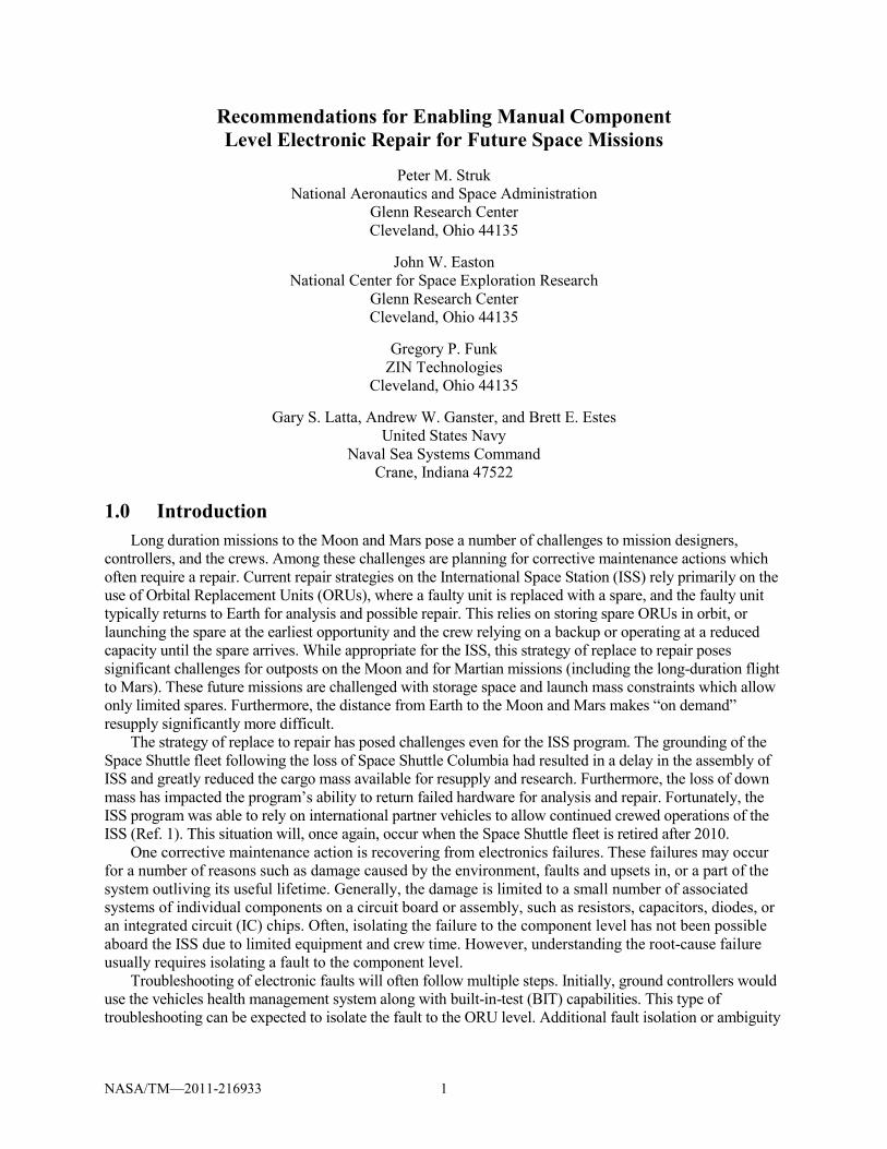
replacing it with a spare unit. Current ORUs have not been designed to readily remove circuit cards from higher-level assemblies. One exception is the Multiplexer-Demultiplexer (MDM). Using BIT capabilities and an external test kit, the crew can isolate a fault on an MDM to the circuit card level. The crew then uses a circuit card puller, shown in Figure 1, to remove the faulty circuit card. Such a design strategy helps facilitate circuit card removal and is recommended for future designs employing circuit cards. However, the crew does not attempt a component-level repair at the circuit card level.
Figure 1.—MDM Circuit Card Puller.
1The CLEAR task was part of the Supportability project of the Exploration Technology Development Program
NASA/TM—2011-216933 3
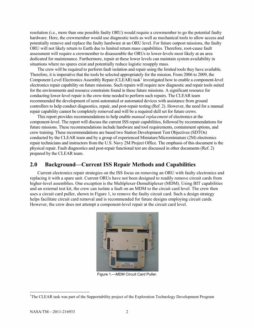
Figure 2.—Soldering iron from the US Soldering Kit, used
on the ISS. The ISS crew also has access to some tools suitable for electronics repairs. The US Soldering Kit,
shown in Figure 2, has a battery powered soldering iron, two Weller PT Series 600 °F soldering iron tips, a spool of solder wire, solder wick, and heat sinks for performing limited soldering and desoldering tasks. This kit has been used in the past for some repairs as well as for scientific (Ref. 3) and engineering studies of solder joint formation (Refs. 3 to 9). While useful, this soldering kit is not ideal for repairs of circuit cards at the component level. Some shortcomings include the maximum tip temperature and temperature control methods as well as the limited number of solder tips available.
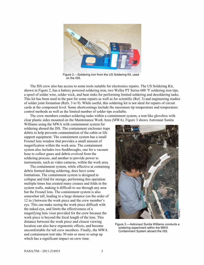
The crew members conduct soldering tasks within a containment system, a tent-like glovebox with clear plastic sides mounted on the Maintenance Work Area (MWA). Figure 3 shows Astronaut Sunita Williams using the MWA with containment system for soldering aboard the ISS. The containment enclosure traps debris to help prevents contamination of the cabin or life support equipment. The containment system has a small Fresnel lens window that provides a small amount of magnification within the work area. The containment system also includes two feedthroughs, one for a vacuum hose to collect gases and debris evolved from the soldering process, and another to provide power to instruments, such as video cameras, within the work area.
The containment system, while effective at containing debris formed during soldering, does have some limitations. The containment system is designed to collapse and fold for storage; performing this operation multiple times has created many creases and folds in the system walls, making it difficult to see through any area but the Fresnel lens. The containment system is also somewhat tall, leading to a large distance (on the order of 12 in.) between the work piece and the crew member’s eye. This can make seeing the work piece difficult with the naked eye, and limits the effectiveness of a magnifying lens visor provided for the crew because the work piece is beyond the focal length of the lens. This distance between the work piece and closest viewing location can also have ergonomic effects, and become uncomfortable for tall crew members. Finally, the MWA and containment tent take 30 min or more to setup up which has a significant impact on crew time.
Figure 3.—Astronaut Sunita Williams conducts a
soldering experiment within the MWA Containment System aboard the ISS.

NASA/TM—2011-216933 4
Crew members also have access to a wide variety of additional tools as shown in Figure 4. For example, the ISS Pin Kit contains jumper wires with various terminations, connectors, pin, and lugs for making wire connections. The various drawers of the IVA Tool Kit contain a number of common hand tools, most of which are appropriate for mechanical rather than electronics tasks, but does include crimper tools used with the pins and lugs found in the Pin Kit. This lack of electronics tools can limit the effectiveness of electronics repairs. Electronics tools, such as tweezers, cutters, and dental picks are smaller than similar tools used for mechanical repairs. These smaller tools are more appropriate for electronics repairs because the items being manipulated by the tools are also small, and the small size of the tools limits heat loss during soldering to the tool, making the soldering task more effective. Large tools may also damage the component under work, adjacent components, and the circuit board if used. Electronics tools often include protection from electrostatic discharge, which can damage components. The crew also has access to a combination multimeter and oscilloscope, logic analyzer, power supply, and other basic electronics diagnosis tools, as well as the dedicated MDM tester already discussed.
Repair tasks aboard the ISS depend on extensive guidance from ground support teams. These teams collect data and reports from the crew after a failure, and use this information to determine a cause of and solution to the failure. These efforts range from working on fully functional mock-ups of flight instruments and systems on the ground, to communicating and meeting with the developer of the instrument, whether within NASA or an outside vendor. The team then develops and tests procedures for a repair, a process that often requires intensive work. The procedures are then transmitted to the crew who, guided by the procedures, attempt to perform a repair and return a faulty device to functioning. To the author’s knowledge, no crew members have attempted to replace a component at the circuit card level of actual flight hardware.
Figure 4.—A sample of tools available aboard the ISS.
Pin Kit
IVA Tool Kit (5 drawers)
Power Drill
Ethernet Repair Crimp Tool
Current Probe Power Supply 1553 Databus Analyzer Logic Analyzer
Breakout Box
Meter
NASA/TM—2011-216933 5
3.0 Recommendations for Future Space Missions To enable component-level electronics repair in future manned space missions, crews will require
significantly more capability than currently available aboard ISS. The entire repair process encompasses fault diagnostics, the physical repair, and acceptance testing post repair. Additionally, crew members need adequate skills based training to be able to respond to a wide variety of potential problems. Each area of the repair process—diagnostics, repair, test, and training—requires more capability and forethought to enable future crews to conduct repairs in a manner consistent with the constraint of spaceflight. One of the primary constraints is that of available crew time. Crewmembers primary mission is to conduct the science and exploration tasks assigned. Repairs, although inevitably necessary, should not require the majority of the available crew time to conduct.
The following sections discuss recommended tools, facilities, training, and design changes to existing hardware to enhance a future crew’s capability to perform manual electronics repairs. Fault diagnostic and post-repair functional test are discussed in other reports (Ref. 2) generated by the CLEAR project. This section begins by differentiating between manual and semi-automated repairs. Next, a variety of hardware recommendations are presented which include soldering tools, other hand tools, a containment system, and visual aids. Then, a recommended crew training approach is presented that includes a training syllabus prior to the flight as well as training materials used during the flight. The hardware and training recommendations come from experience gathered from developing two ISS Station Development Test Objectives (Refs. 10 to 12) and a study conducted by the U.S. Navy 2M Project Office. Finally, some discussion regarding suggested design changes to ORUs will conclude the recommendations.
3.1 Manual versus Semi-Automated Repair
Manual repairs are defined as those accomplished with the majority of manipulation done by crew members. There are a wide variety of tools that minimize the physical manipulation required by human hands—these tools are referred to as semi-automated. Examples of such tools include probing devices and rework stations. Earlier reports (Ref. 2) by the CLEAR project discuss an approach to developing semi-automated tools to repair electronic circuit boards. Some of the semi-automated tools include diagnostic probers and automated soldering systems which offer a tremendous advantage to the crewmembers. For example, probing a circuit board for a fault can involve probing hundreds of locations on a circuit board. Also, automated soldering can minimize the potential of overhearing a component during repair. While semi-automated tools offer the potential to minimize valuable crew time, they can add significant complexity to systems. Simple manual tools help alleviate that complexity. Therefore, it is important to understand the capabilities and limitations of manual repair.
A manual repair capability can augment a semi-automated repair system as follows: • First, manual systems are typically portable which is important for situations where bringing the
failed hardware to another location is not practical. • A second area of consideration for manual systems is in the size of the failed component. Some
components, such as resistors or capacitors when compared with typical integrated circuit packaging, lend themselves more naturally to manual repair and may present operational difficulties for a semi-automated system. A manual tool set will provide an easier method for working with such components.
• Third, semi-automated systems may not provide a method of repairing all expected repair tasks. You will still need a manual repair capability for such contingencies.
• Fourth, manual systems may provide a faster resolution to a problem, particularly if the fault is minor and easily repaired. An example of such a situation is re-soldering leads for a battery clip to a circuit board in a handheld multimeter.
NASA/TM—2011-216933 6
• Fifth, manual repair capabilities provide multitasking opportunities where a larger or complicated task may be performed on the semi-automated system while a crew member works a smaller or less complicated task, decreasing the amount of time needed to recover from a fault.
• Finally, in the case where the semi-automated repair system experiences a fault, the manual system provides a means for repairing the semi-automated system, or to repair other faults.
In summary, manual tools offer flexibility.
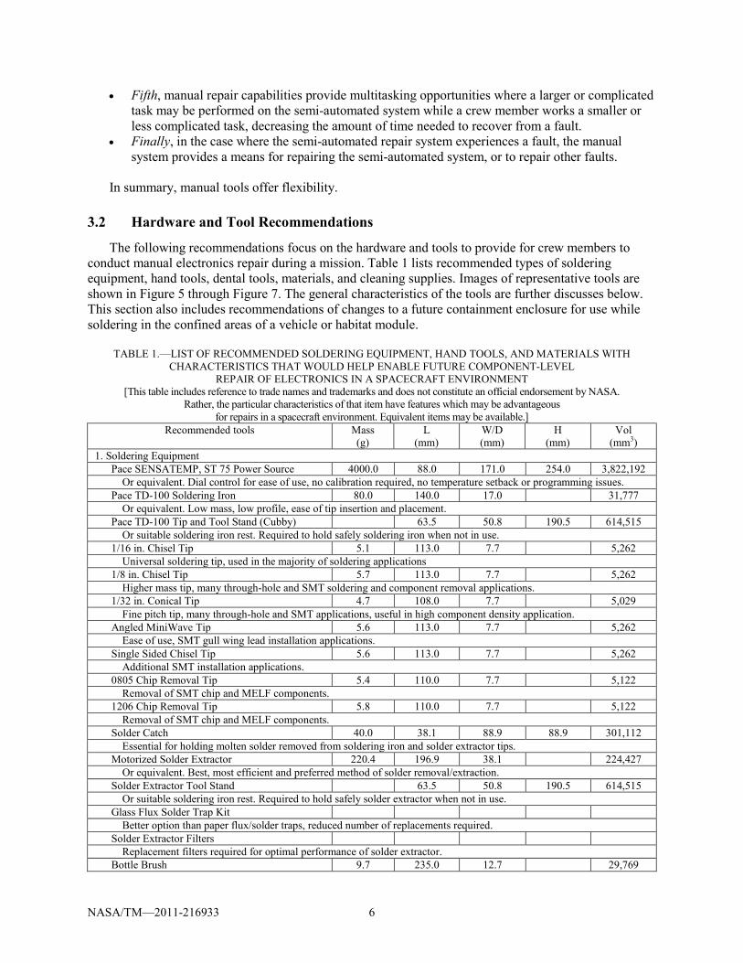
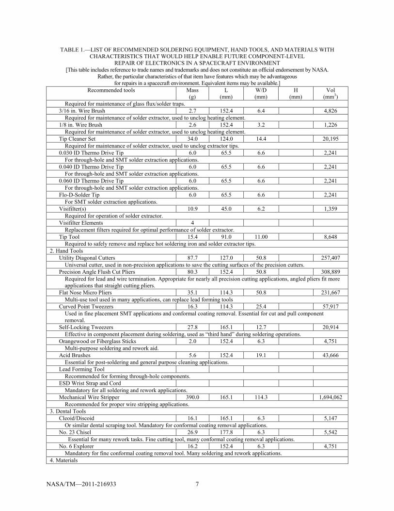
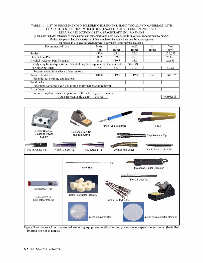
3.2 Hardware and Tool Recommendations
The following recommendations focus on the hardware and tools to provide for crew members to conduct manual electronics repair during a mission. Table 1 lists recommended types of soldering equipment, hand tools, dental tools, materials, and cleaning supplies. Images of representative tools are shown in Figure 5 through Figure 7. The general characteristics of the tools are further discusses below. This section also includes recommendations of changes to a future containment enclosure for use while soldering in the confined areas of a vehicle or habitat module.
TABLE 1.—LIST OF RECOMMENDED SOLDERING EQUIPMENT, HAND TOOLS, AND MATERIALS WITH
CHARACTERISTICS THAT WOULD HELP ENABLE FUTURE COMPONENT-LEVEL REPAIR OF ELECTRONICS IN A SPACECRAFT ENVIRONMENT
[This table includes reference to trade names and trademarks and does not constitute an official endorsement by NASA. Rather, the particular characteristics of that item have features which may be advantageous
for repairs in a spacecraft environment. Equivalent items may be available.] Recommended tools Mass
(g) L
(mm) W/D (mm)
H (mm)
Vol (mm3)
1. Soldering Equipment Pace SENSATEMP, ST 75 Power Source 4000.0 88.0 171.0 254.0 3,822,192 Or equivalent. Dial control for ease of use, no calibration required, no temperature setback or programming issues. Pace TD-100 Soldering Iron 80.0 140.0 17.0 31,777 Or equivalent. Low mass, low profile, ease of tip insertion and placement. Pace TD-100 Tip and Tool Stand (Cubby) 63.5 50.8 190.5 614,515 Or suitable soldering iron rest. Required to hold safely soldering iron when not in use. 1/16 in. Chisel Tip 5.1 113.0 7.7 5,262 Universal soldering tip, used in the majority of soldering applications 1/8 in. Chisel Tip 5.7 113.0 7.7 5,262 Higher mass tip, many through-hole and SMT soldering and component removal applications. 1/32 in. Conical Tip 4.7 108.0 7.7 5,029 Fine pitch tip, many through-hole and SMT applications, useful in high component density application. Angled MiniWave Tip 5.6 113.0 7.7 5,262 Ease of use, SMT gull wing lead installation applications. Single Sided Chisel Tip 5.6 113.0 7.7 5,262 Additional SMT installation applications. 0805 Chip Removal Tip 5.4 110.0 7.7 5,122 Removal of SMT chip and MELF components. 1206 Chip Removal Tip 5.8 110.0 7.7 5,122 Removal of SMT chip and MELF components. Solder Catch 40.0 38.1 88.9 88.9 301,112 Essential for holding molten solder removed from soldering iron and solder extractor tips. Motorized Solder Extractor 220.4 196.9 38.1 224,427 Or equivalent. Best, most efficient and preferred method of solder removal/extraction. Solder Extractor Tool Stand 63.5 50.8 190.5 614,515 Or suitable soldering iron rest. Required to hold safely solder extractor when not in use. Glass Flux Solder Trap Kit Better option than paper flux/solder traps, reduced number of replacements required. Solder Extractor Filters Replacement filters required for optimal performance of solder extractor. Bottle Brush 9.7 235.0 12.7 29,769
NASA/TM—2011-216933 7
TABLE 1.—LIST OF RECOMMENDED SOLDERING EQUIPMENT, HAND TOOLS, AND MATERIALS WITH CHARACTERISTICS THAT WOULD HELP ENABLE FUTURE COMPONENT-LEVEL
REPAIR OF ELECTRONICS IN A SPACECRAFT ENVIRONMENT [This table includes reference to trade names and trademarks and does not constitute an official endorsement by NASA.
Rather, the particular characteristics of that item have features which may be advantageous for repairs in a spacecraft environment. Equivalent items may be available.]
Recommended tools Mass (g)
L (mm)
W/D (mm)
H (mm)
Vol (mm3)
Required for maintenance of glass flux/solder traps. 3/16 in. Wire Brush 2.7 152.4 6.4 4,826 Required for maintenance of solder extractor, used to unclog heating element. 1/8 in. Wire Brush 2.6 152.4 3.2 1,226 Required for maintenance of solder extractor, used to unclog heating element. Tip Cleaner Set 34.0 124.0 14.4 20,195 Required for maintenance of solder extractor, used to unclog extractor tips. 0.030 ID Thermo Drive Tip 6.0 65.5 6.6 2,241 For through-hole and SMT solder extraction applications. 0.040 ID Thermo Drive Tip 6.0 65.5 6.6 2,241 For through-hole and SMT solder extraction applications. 0.060 ID Thermo Drive Tip 6.0 65.5 6.6 2,241 For through-hole and SMT solder extraction applications. Flo-D-Solder Tip 6.0 65.5 6.6 2,241 For SMT solder extraction applications. Visifilter(s) 10.9 45.0 6.2 1,359 Required for operation of solder extractor. Visifilter Elements 4 Replacement filters required for optimal performance of solder extractor. Tip Tool 15.4 91.0 11.00 8,648 Required to safely remove and replace hot soldering iron and solder extractor tips. 2. Hand Tools Utility Diagonal Cutters 87.7 127.0 50.8 257,407 Universal cutter, used in non-precision applications to save the cutting surfaces of the precision cutters. Precision Angle Flush Cut Pliers 80.3 152.4 50.8 308,889 Required for lead and wire termination. Appropriate for nearly all precision cutting applications, angled pliers fit more
applications that straight cutting pliers. Flat Nose Micro Pliers 35.1 114.3 50.8 231,667 Multi-use tool used in many applications, can replace lead forming tools Curved Point Tweezers 16.3 114.3 25.4 57,917 Used in fine placement SMT applications and conformal coating removal. Essential for cut and pull component
removal. Self-Locking Tweezers 27.8 165.1 12.7 20,914 Effective in component placement during soldering, used as “third hand” during soldering operations. Orangewood or Fiberglass Sticks 2.0 152.4 6.3 4,751 Multi-purpose soldering and rework aid. Acid Brushes 5.6 152.4 19.1 43,666 Essential for post-soldering and general purpose cleaning applications. Lead Forming Tool Recommended for forming through-hole components. ESD Wrist Strap and Cord Mandatory for all soldering and rework applications. Mechanical Wire Stripper 390.0 165.1 114.3 1,694,062 Recommended for proper wire stripping applications. 3. Dental Tools Cleoid/Discoid 16.1 165.1 6.3 5,147 Or similar dental scraping tool. Mandatory for conformal coating removal applications. No. 23 Chisel 26.9 177.8 6.3 5,542
Essential for many rework tasks. Fine cutting tool, many conformal coating removal applications. No. 6 Explorer 16.2 152.4 6.3 4,751 Mandatory for fine conformal coating removal tool. Many soldering and rework applications. 4. Materials
NASA/TM—2011-216933 8
TABLE 1.—LIST OF RECOMMENDED SOLDERING EQUIPMENT, HAND TOOLS, AND MATERIALS WITH CHARACTERISTICS THAT WOULD HELP ENABLE FUTURE COMPONENT-LEVEL
REPAIR OF ELECTRONICS IN A SPACECRAFT ENVIRONMENT [This table includes reference to trade names and trademarks and does not constitute an official endorsement by NASA.
Rather, the particular characteristics of that item have features which may be advantageous for repairs in a spacecraft environment. Equivalent items may be available.]
Recommended tools Mass (g)
L (mm)
W/D (mm)
H (mm)
Vol (mm3)
Solder 453.6 57.0 52.0 121,052 Flux or Flux Pen 18.2 139.5 15.6 26,663 Alcohol (Alcohol Pen Dispenser) 18.2 139.5 15.6 26,663 Only very limited quantities of alcohol may be evaporated in the atmosphere of the ISS. De-Soldering Wick 7.5 46.0 11.0 4,372 Recommended for surface solder removal. Tissues, Lint-Free 104.0 119.0 119.0 75.0 1,062,075 Essential for cleaning applications. Toothpicks Fine pitch soldering aid. Used in fine conformal coating removal. Extra Fuses Required replacements for operation of the soldering power source.
Totals (for available data) 5787.1 9,595,383
Figure 5.—Images of recommended soldering equipment to allow for component-level repair of electronics. (Note that
images are not to scale.)
Single Sided Chisel Tip
Chip Removal Tip
Wire Brush
1 of 4 items in flux / solder trap kit
Flo-D Solder Tip
In-line extractor filter element In-line extractor filter
1/16 in. Chisel Tip 1/8 in. Chisel Tip 1/32 Conical Tip Angled Mini Wave
Motorized Extractor
Single Channel Soldering Power
Supply
Soldering Iron Tip and Tool Stand
Pencil Type Soldering I
Tip Tool
Motorized Solder Extractor
Solder Extractor Filterers
Flux/Solder Trap
NASA/TM—2011-216933 9
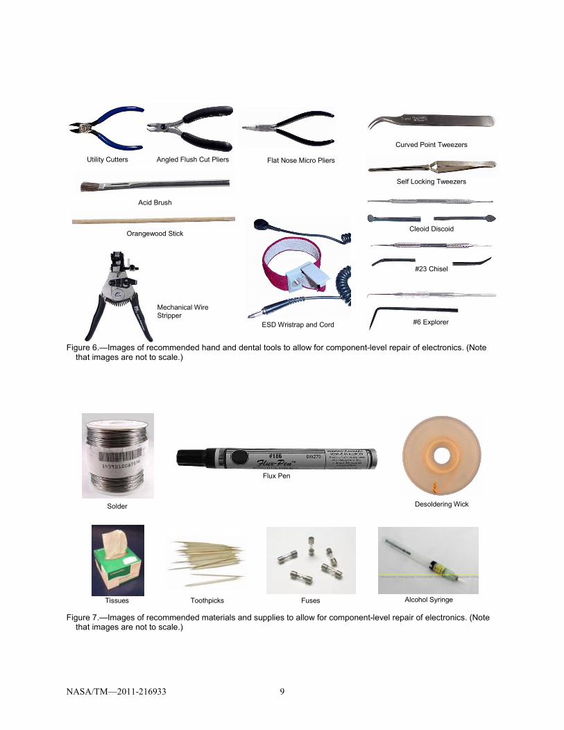
Figure 6.—Images of recommended hand and dental tools to allow for component-level repair of electronics. (Note
that images are not to scale.)
Figure 7.—Images of recommended materials and supplies to allow for component-level repair of electronics. (Note
that images are not to scale.)
Flux Pen
Solder Desoldering Wick
Toothpicks Fuses Alcohol Syringe Tissues
Mechanical Wire Stripper
Utility Cutters Angled Flush Cut Pliers Flat Nose Micro Pliers
Curved Point Tweezers
Self Locking Tweezers
Cleoid Discoid
#23 Chisel
#6 Explorer
Acid Brush
Orangewood Stick
ESD Wristrap and Cord
NASA/TM—2011-216933 10
3.2.1 Soldering Equipment In comparison to the existing US Soldering Kit, this report recommends both different and additional
soldering tools for component-level electronics repair.
3.2.1.1 Soldering Iron and Power Source The current US Soldering Kit limits the maximum temperature for soldering to 600 °F. It is common
industry practice to use 700 °F tips for general soldering applications requiring the use of alloys containing lead. For the higher melting point lead-free alloys, a slightly higher temperature is generally required. The temperature control of the existing soldering iron is not the best choice for repair applications. For most repair applications, we would recommend the use of a higher-end, electronically-adjustable soldering stations (e.g., those that can be adjusted in 1° increments to satisfy the needs of the actual application) which is not available with the curie point style tips2 currently in use aboard ISS. Furthermore, soldering irons which do not require calibration are desired.
Should a higher-temperature tip be problematic to certify for use in spacecraft, another alternative is a backplane heater (although this increases the equipment to be carried). A back plane heater would bring the entire board to just below the reflow temperature of solder. The crew member would then use the soldering iron to heat specific joints to the reflow temperature to complete the repair task. The use of a back plane heater makes the soldering tasks easier in a number of ways. Less heat from the soldering iron is required at the specific joint to reach reflow temperatures, which requires less time with the soldering iron tip on the joint. The soldering iron tip does not have to be as hot as in the case where the circuit board is at room temperature, because the heater provides most of the energy instead of the soldering iron tip. Heating the circuit board with the backplane heater also reduces thermal shock to the board by reducing the temperature gradient between the board components and soldering iron tip.
A recommended power source (1a), soldering iron (1b), and tool holder (1c), or their equivalents, are listed in Table 1 and shown in Figure 5. It is noted that a constant power source compared with a battery power source is preferred because the latter may reduce soldering effectiveness as the battery drains. However, both can produce equivalent results if control circuitry is properly designed.
3.2.1.2 Soldering Iron Tips The available tips in the US Soldering Kit only include one style tips—a screwdriver shape. Smaller
or other shapes are required to more easily work with many component types including surface mount technology (SMT). Table 1 and Figure 5 show a recommended selection of tips (1d to 1j) to cover a majority of soldering applications including those appropriate for SMT.
3.2.1.3 Solder Extraction A number of tools are required to extract solder and maintain the solder extraction equipment (see
items 1k to 1y and 4d in Table 1 and shown in Figure 5 and Figure 7).
3.2.2 Hand and Dental Tools While the existing ISS IVA Toolkit has a number of hand tools available, most are not suited for use
in electronics repairs due to size. The tools must be sized correctly for the task at hand. Often electronics components have small features, such as small, closely spaced leads, or the component itself is small. Components of these sizes require tools to manipulate the smaller components. Examples of some needed additional tools are listed in Table 1 and shown in Figure 6. These include cutters, pliers, tweezers, conformal coating removal tools, lead-forming tools, ESD protection, and wire strippers. Tools used to manipulate components during soldering should have smaller contact area and thermal mass to limit heat 2Curie style soldering tips use magnetized soldering tips which lose their magnetic properties at a certain temperature (the Curie point). As long as the tip is magnetic, it clings to the heating element. At the design (Curie) temperature, it loses contact, cooling down.
NASA/TM—2011-216933 11
loss. Cutters should have jaws to allow cutting close to component bodies or in tight spaces on a circuit board. Fiberglass (or orangewood) sticks, dental tools, and even toothpicks are needed for removing conformal coating, reapplying conformal coating, or as a tool to position a component on the circuit board. The fiberglass in the stick will not wear away as readily, as a wooden stick would, when removing conformal coating. The stick will also limit damage due to shorts or static build-up during use. Other aspects of tools include designs which reduce user fatigue as well as ensuring that the tools are not mishandled or used for applications other for which they were intended.
3.2.3 Materials and Supplies The needed materials and supplies include solder, external solder flux or flux pen, alcohol or alcohol
pen, and de-soldering wick. Additional supplies which may be part of a general supply kit include tissues (lint-free), toothpicks, and extra fuses.
3.2.3.1 Solder The 60/40 Sn/Pb solder with a RA flux core in the current ISS Soldering Kit is not recommended due
to the highly active rosin flux core. The residue left behind from soldering with such a solder normally requires removal with some solvent like alcohol. More discussion of flux is presented in a subsequent section.
Previous work (Refs. 4, 5, and 7) showed an increase in void defects formed while soldering in reduced gravity. To help mitigate the increase of voids, various combinations of solder and flux were evaluated (Refs. 8 and 9) including a solid-core wire with an externally applied flux. These materials and techniques were ultimately tested aboard the ISS as part of the Soldering in Reduced Gravity Experiment (SoRGE)(Ref. 11). A flux-cored solder wire was the easiest to solder compared with a solid-core wire with externally applied flux. Joints formed with the eutectic (63/37 Sn/Pb) solder wire generally had fewer internal voids than those formed with the 60/40 rosin-flux-cored solder (Ref. 9).
On the basis of the results of SoRGE, the CLEAR team recommends eutectic rosin-flux-cored solder wire for general electronics repairs in future missions. This type of solder wire represents a compromise between void formation and ease of use appropriate for most repair tasks. In industry the amount of acceptable voiding depends on the function and criticality of the overall product, and each manufacturer must make this decision separately, with very few rules of thumb to guide the decision. Where applications require more extensive void mitigation, NASA may require additional void mitigation techniques and materials, such as the use of solid solder wire and external liquid rosin flux. However, such techniques will require additional training and practice by the crew.
Today, lead-free solder is becoming commonplace in commercial electronics industry as a result of the Restriction of Hazardous Substances Directive (RoHS) put in place by European environmental legislative actions (Ref. 13). At the time this document was written, NASA was still using Pb-based solders for high reliability electronics in space applications. However, it is expected that NASA and DoD will ultimately be pushed to lead-free solders for space applications. The CLEAR project has collected only limited data on lead-free solders and further work is required to ascertain its affects on in-situ electronics repair. Other projects have begun evaluating lead-free soldering in space (Ref. 14).
3.2.3.2 Flux Some types of flux, such as rosin active (RA) or rosin mildly active (RMA), are acidic and can, over
time, damage the solder joints. Additionally, the flux residue can, with many conformal coating materials, interfere with the adhesion between the circuit board and coating material. Therefore, such residue must be removed after soldering and usually requires large amounts of solvent, typically alcohol which use is very limited in spacecraft environments (see below).
Therefore, the CLEAR team recommends a no-clean type of flux to minimize the need for cleaning the circuit board post soldering. Residue from this type of flux would not damage the circuit boards or joints, reducing or eliminating the need to clean the joint areas. In many cases, the residue may be safely
NASA/TM—2011-216933 12
covered with conformal coating. During the CRE-1 experiment (Ref. 12), astronauts successfully conducted soldering operations using a no-clean type of flux.
3.2.3.3 Alcohol Processes that minimize or eliminate the use of alcohol for cleaning are recommended for in-space
repairs. Currently, only 1 cc of alcohol may be evaporated daily into the volume of the ISS without causing problems for the environmental control systems. It is anticipated that such limitations will exist with future space environmental system (R.M. Bagdigian, personal communication, October 3, 2008). In addition to the environmental concerns, handling the fluid can be difficult in reduced gravity. If alcohol is ultimately required then controlled methods of dispensing will be required. Such methods could include dispensing syringes, pens, or swabs; containment; and/or reclaiming evaporated alcohol.
3.2.3.4 Solder Wick There are two primary ways for removing solder from circuit boards: vacuum pumps (solder suckers
or extractors) and solder wick. Each technique has specific areas when they are used although both techniques can accomplish solder removal in similar applications. However, solder wick is ideal for use in removing solder from surface mount applications. Solder wick is typically made from copper and often contains some flux material. Care must be taken to specify a no-clean type flux in the solder wick otherwise the board may require solvents to clean.
3.2.4 Specialty Tools and Repair Kits The tool recommendations discussed in this paper focus on the removal and replacement of electronic
components using primarily soldering. Other electronics repairs may arise which require specialty tools or dedicated repair kits. Such kits would include not only the material required for such repairs but also “how to” instructional information. Examples of dedicated electronic repair kits include those needed for the repair and modification of traces, lands, contact fingers, SMT pads, plated hole connections, and PCB base board material.
For the example of trace or land repair on a circuit board, a rotary hand/abrasion tool may be required to excavate around the trace or access an internal trace. Furthermore, chemicals are needed to clean or bond replacement parts, requiring tools to apply and handle the chemicals. While some tools, such as the rotary hand tool, may be available as a part of a general tool kit, most other tools for this or similar tasks will not, and must be included in a dedicated electronics repair tool kit. The amount of epoxy required to perform conductor repair, both surface and sub-surface, may be too much for the closed environment of a spacecraft to handle. For some repairs, common terrestrial based practices may require substitute procedures for operations in space. As a potential alternative, surface conductor repair can be attempted by soldering the replacement in place and applying conformal coating to secure the repair.
Such repair tool kit require further evaluation for use in a spacecraft environment.
3.2.5 Containment Enclosure and Visual Aids The existing containment enclosure, used with the MWA on the ISS, has a number of shortcomings
that are specific to conducting component-level repair of electronics. The following recommendations focus on design considerations for a new containment enclosure. This discussion will also examine visual aids which may be included in a future containment enclosure, or as stand-alone instruments with applications beyond electronics repair.
Perhaps the single most important recommendation is to have an enclosure which will allow crew members to comfortably see and manipulate small parts within the enclosure. Terrestrially, technicians do not normally use an enclosure and are typically within 12 in. of the circuit card. With regard to the physical characteristics, the containment enclosure should have rigid sides, to avoid problems with visibility through the current soft sided enclosure, and a clear window to allow easy viewing of the CCA. The enclosure should still be collapsible to aid in stowage although less setup time would be highly
NASA/TM—2011-216933 13
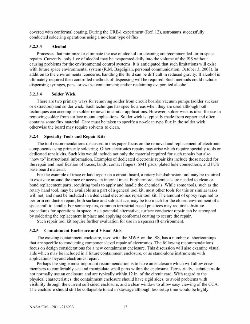
Figure 8.—Setting up a video camera to record a soldering process.
The camera view screen is used as a visual aid.
desirable as the current design requires at least 30 min for setup. As with the current design, the enclosure should have electronic feedthroughs and holes for a vacuum cleaner. The enclosure should be sized to accommodate most, if not all, circuit boards a crew member would work on, with enough volume to accommodate the soldering tool, board clamp or other tools and instruments that may be necessary.
Visual aids can improve the visibility for the crew while performing a repair. Many of the component legs and circuit card pads manipulated in a repair task are small, and working with these small parts may be difficult and taxing on the crew member, if using only the naked eye. Visual aids that can alleviate or eliminate these problems include magnifying lenses, which can be used in a standalone fashion, as part of the enclosure wall, incorporated in lighting, as a visor the crew member wears, or in other ways. Low power microscopes (on the order of 20 X magnifications) are commonly used in ground laboratories and workshops, and can be used with the flat sides of an enclosure in a space vehicle or habitat setting. Video cameras with macro lenses may also be used to magnify the work area, shown in Figure 8 for example, with the benefit of recording the repair session for future analysis. Mission planners should include multiple choices among the visual aids as well, allowing crew members to be flexible in terms of using the appropriate magnifier for the task at hand, available light levels, transmitting or recording video, and personal preference.
3.2.6 Diagnostics to Support Manual Repair Diagnostics tools are essential to performing any electronics repair in order to isolate the failed
component or components requiring replacement as well as to begin determining the root cause of the failure. The diagnostic instruments already found on the ISS (see Figure 4 for some of these instruments) represent only a subset of tools required for component-level electronic repairs of CCAs. Other documents (Ref. 2) generated by the CLEAR team recommended equipment and strategies to address fault diagnosis and functional test. These include a combination of increased BIT capabilities, signature analysis devices, and synthetic instrumentation which can be programmed to meet a specific diagnostic and test needs.
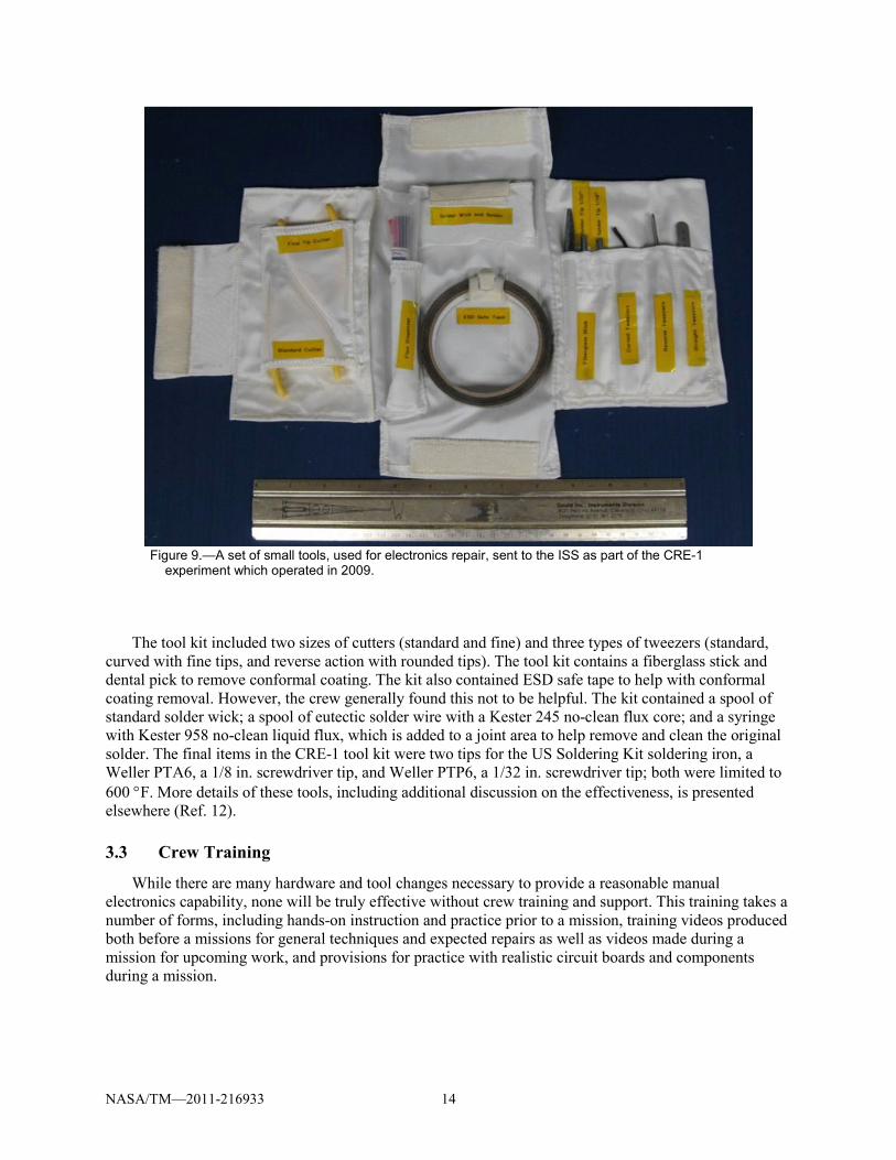
3.2.7 Component Repair Experiment-1 Tool Kit An image of those tools sent to the ISS for the CRE-1 experiment is shown in Figure 9. The tools
provided were a subset of those recommended here due to volume constraints for launch. CRE-1 successfully operated in 2009. However, these tools remain aboard the ISS for future potential repairs. As shown in Figure 9, a small white fabric pouch stores the tools when not in use.
NASA/TM—2011-216933 14
Figure 9.—A set of small tools, used for electronics repair, sent to the ISS as part of the CRE-1
experiment which operated in 2009. The tool kit included two sizes of cutters (standard and fine) and three types of tweezers (standard,
curved with fine tips, and reverse action with rounded tips). The tool kit contains a fiberglass stick and dental pick to remove conformal coating. The kit also contained ESD safe tape to help with conformal coating removal. However, the crew generally found this not to be helpful. The kit contained a spool of standard solder wick; a spool of eutectic solder wire with a Kester 245 no-clean flux core; and a syringe with Kester 958 no-clean liquid flux, which is added to a joint area to help remove and clean the original solder. The final items in the CRE-1 tool kit were two tips for the US Soldering Kit soldering iron, a Weller PTA6, a 1/8 in. screwdriver tip, and Weller PTP6, a 1/32 in. screwdriver tip; both were limited to 600 °F. More details of these tools, including additional discussion on the effectiveness, is presented elsewhere (Ref. 12).
3.3 Crew Training
While there are many hardware and tool changes necessary to provide a reasonable manual electronics capability, none will be truly effective without crew training and support. This training takes a number of forms, including hands-on instruction and practice prior to a mission, training videos produced both before a missions for general techniques and expected repairs as well as videos made during a mission for upcoming work, and provisions for practice with realistic circuit boards and components during a mission.
NASA/TM—2011-216933 15
3.3.1 Preflight Training Crew training prior to a mission should focus on establishing a basic skill set appropriate for most
electronics repair tasks. This basic skill set should establish and reinforce the fundamentals of handling circuit boards and electronics components, heating solder to flow for removing or forming solder joints without damaging the circuit board or components, and working with mechanical aspects of repairs such as crimping pins and wires, removing and replacing conformal coating, and potentially including more advanced tasks such as repairing damaged circuit board lands and traces.
A study performed by the U.S. Navy (NAVSEA, Crane, Indiana) showed this training can be accomplished with as little as 16 hr of intensive instruction, even for crew members with little or no previous electronics or soldering experience. A curriculum was developed by a group of experienced 2M electronic repair technicians and instructors that are on staff in the 2M Project Office. Topics were selected by consensus on the basic concepts and skills that are required for an individual to perform successful electronic rework and repair tasks. It was assumed that the tools and hardware presented earlier in this document were available. The technicians conducted a feasibility study for providing basic soldering training to two Electronic Engineers with no previous soldering experience. The two trainees were instructed individually, one-on-one, by experienced 2M Instructors. Each training topic and rework/repair task was timed and the results of the training weighed heavily in the selection of training topics and tasks that were chosen in the final draft of the curriculum. The trainees proved to be fairly proficient in their tasks after training, the actual time taken by the trainees to perform the rework/repair tasks was quite longer than anticipated. After the results of the training sessions were compiled, the 2M Project group reviewed the results and provided recommendations on what topics and tasks to retain, taking into consideration the time factors of the training.
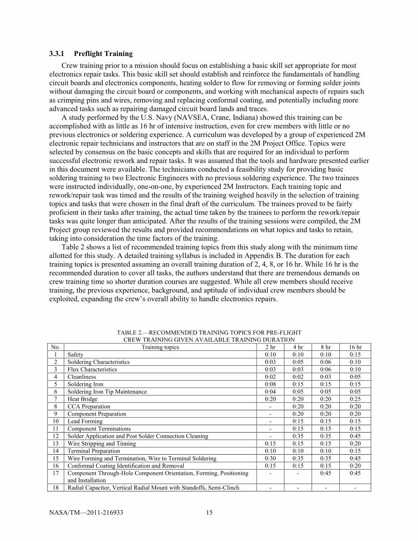
Table 2 shows a list of recommended training topics from this study along with the minimum time allotted for this study. A detailed training syllabus is included in Appendix B. The duration for each training topics is presented assuming an overall training duration of 2, 4, 8, or 16 hr. While 16 hr is the recommended duration to cover all tasks, the authors understand that there are tremendous demands on crew training time so shorter duration courses are suggested. While all crew members should receive training, the previous experience, background, and aptitude of individual crew members should be exploited, expanding the crew’s overall ability to handle electronics repairs.
TABLE 2.—RECOMMENDED TRAINING TOPICS FOR PRE-FLIGHT CREW TRAINING GIVEN AVAILABLE TRAINING DURATION
No. Training topics 2 hr 4 hr 8 hr 16 hr 1 Safety 0:10 0:10 0:10 0:15 2 Soldering Characteristics 0:03 0:05 0:06 0:10 3 Flux Characteristics 0:03 0:03 0:06 0:10 4 Cleanliness 0:02 0:02 0:03 0:05 5 Soldering Iron 0:08 0:15 0:15 0:15 6 Soldering Iron Tip Maintenance 0:04 0:05 0:05 0:05 7 Heat Bridge 0:20 0:20 0:20 0:25 8 CCA Preparation - 0:20 0:20 0:20 9 Component Preparation - 0:20 0:20 0:20
10 Lead Forming - 0:15 0:15 0:15 11 Component Terminations - 0:15 0:15 0:15 12 Solder Application and Post Solder Connection Cleaning - 0:35 0:35 0:45 13 Wire Stripping and Tinning 0:15 0:15 0:15 0:20 14 Terminal Preparation 0:10 0:10 0:10 0:15 15 Wire Forming and Termination, Wire to Terminal Soldering 0:30 0:35 0:35 0:45 16 Conformal Coating Identification and Removal 0:15 0:15 0:15 0:20 17 Component Through-Hole Component Orientation, Forming, Positioning
and Installation - - 0:45 0:45
18 Radial Capacitor, Vertical Radial Mount with Standoffs, Semi-Clinch - - - -
NASA/TM—2011-216933 16
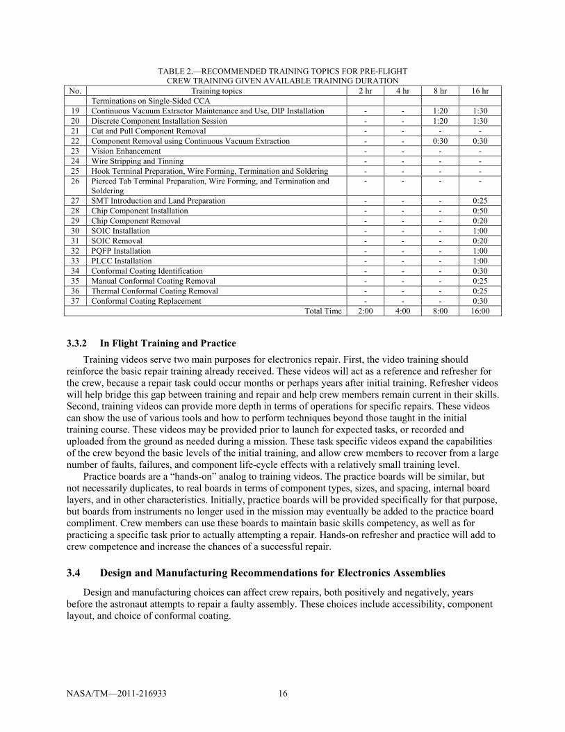
TABLE 2.—RECOMMENDED TRAINING TOPICS FOR PRE-FLIGHT CREW TRAINING GIVEN AVAILABLE TRAINING DURATION
No. Training topics 2 hr 4 hr 8 hr 16 hr Terminations on Single-Sided CCA
19 Continuous Vacuum Extractor Maintenance and Use, DIP Installation - - 1:20 1:30 20 Discrete Component Installation Session - - 1:20 1:30 21 Cut and Pull Component Removal - - - - 22 Component Removal using Continuous Vacuum Extraction - - 0:30 0:30 23 Vision Enhancement - - - - 24 Wire Stripping and Tinning - - - - 25 Hook Terminal Preparation, Wire Forming, Termination and Soldering - - - - 26 Pierced Tab Terminal Preparation, Wire Forming, and Termination and
Soldering - - - -
27 SMT Introduction and Land Preparation - - - 0:25 28 Chip Component Installation - - - 0:50 29 Chip Component Removal - - - 0:20 30 SOIC Installation - - - 1:00 31 SOIC Removal - - - 0:20 32 PQFP Installation - - - 1:00 33 PLCC Installation - - - 1:00 34 Conformal Coating Identification - - - 0:30 35 Manual Conformal Coating Removal - - - 0:25 36 Thermal Conformal Coating Removal - - - 0:25 37 Conformal Coating Replacement - - - 0:30
Total Time 2:00 4:00 8:00 16:00
3.3.2 In Flight Training and Practice Training videos serve two main purposes for electronics repair. First, the video training should
reinforce the basic repair training already received. These videos will act as a reference and refresher for the crew, because a repair task could occur months or perhaps years after initial training. Refresher videos will help bridge this gap between training and repair and help crew members remain current in their skills. Second, training videos can provide more depth in terms of operations for specific repairs. These videos can show the use of various tools and how to perform techniques beyond those taught in the initial training course. These videos may be provided prior to launch for expected tasks, or recorded and uploaded from the ground as needed during a mission. These task specific videos expand the capabilities of the crew beyond the basic levels of the initial training, and allow crew members to recover from a large number of faults, failures, and component life-cycle effects with a relatively small training level.
Practice boards are a “hands-on” analog to training videos. The practice boards will be similar, but not necessarily duplicates, to real boards in terms of component types, sizes, and spacing, internal board layers, and in other characteristics. Initially, practice boards will be provided specifically for that purpose, but boards from instruments no longer used in the mission may eventually be added to the practice board compliment. Crew members can use these boards to maintain basic skills competency, as well as for practicing a specific task prior to actually attempting a repair. Hands-on refresher and practice will add to crew competence and increase the chances of a successful repair.
3.4 Design and Manufacturing Recommendations for Electronics Assemblies
Design and manufacturing choices can affect crew repairs, both positively and negatively, years before the astronaut attempts to repair a faulty assembly. These choices include accessibility, component layout, and choice of conformal coating.
NASA/TM—2011-216933 17
3.4.1 Accessibility In addition to the layout of a circuit board, designers must also consider the layout and design of the
enclosure and internal components. This includes both mechanical as well as electrical or electronic aspects. First, the enclosure must be designed to be opened by crew members in reduced gravity. Historically, a small number of ORUs on the ISS or Space Shuttle have riveted enclosures, preventing the crew from accessing the interior. Other enclosures use screws to assemble the enclosure; while these screws allow the crew to access the circuit boards within the ORU, loose small parts in reduced gravity can pose additional problems if a part is lost or becomes lodged in a nearby device. Finally, the enclosures should use a minimum number of fasteners to avoid extensive crew time needed for disassembly.
Designers should consider the tools and environment available to the crew during a repair task when mechanically designing an ORU enclosure. Designers must also consider aspects of the interior design as well. This includes designing the circuit card mounting, connections, and spacing so that crew members can remove the circuit boards without further damage to the faulty circuit board or any other internal components. This includes minimizing soldered connections between a circuit board and other parts of an ORU. Finally, heat sinks and cold plates can pose access difficulties during crew repairs. Crew members must be able to remove or work around heat sinks and cold plates, which not only hinder removing a circuit board or other part from an ORU, but could make soldering and other repairs to a circuit board difficult if the heat sink is still in place. Designers must take all these factors into account when designing ORU enclosures and internal layouts.
3.4.2 Component Layout The layout and component selection for circuit boards directly affects the ability of crew members to
remove and replace components when faults occur. Electronics manufacturers strive for ever smaller devices, leading to ever smaller components placed closer and closer together. NASA engineers take advantage of these small components as well, to reduce the volume and mass of the devices and modules they build for use in space missions. These small components and close spacing, however, require increasing training and skill, more specialized tools, and eventually machines such as solder reflow stations for assembly and repair. For an in situ repair plan to be feasible, the crew must have the appropriate training and tools to work on these increasingly difficult parts. Designers must know in advance the level of training, tools, and any other resources available to the crew so appropriate design choices can be made to allow in situ repair. This is not to say that all electronics must be designed for repair by crew members. Designers may have valid reasons to use components and layouts beyond the crew's repair capabilities, but should be aware of these limitations and the implications of designing outside, as well as within, the crew's capabilities.
Adding test points on the circuit board are another design change that can greatly aid crew members performing electronics repair during a mission. The test points are pads on the circuit board which allow a user to probe a circuit with a multimeter or oscilloscope without requiring the probes to contact small areas, such as component legs or traces on the circuit board. This makes diagnosis of a circuit board easier, and as a consequence more accurate, by increasing access to vital areas of a circuit. These test points would not only make diagnosis tasks easier for the crew, but would also make the tasks easier to configure and conduct on automated probing equipment.
3.4.3 Conformal Coating The choice of conformal coating on a CCA can facilitate or inhibit component-level repair of
electronics. Conformal coatings are intended to provide electrical insulation and environmental protection. There are five basic categories of conformal coating: acrylic resin, epoxy resin, parylene, polyurethane resin (urethane), and silicone resin. Parylene and polyurethane resin are typically used for space applications which see a vacuum environment.
The ability to remove a conformal coating depends on the tooling available. Manual removal of conformal coating requires abrasive tools. For coatings other that silicone, a sharp tool such as a dental

NASA/TM—2011-216933 18
pick is also required. In addition, a controlled heat abrasion (perhaps with a heat gun) can ease the removal. Finally, some conformal coatings such as acrylic can be easily removed with isopropyl alcohol. However, alcohol evaporation into the cabin atmosphere is not desired for a spacecraft environmental and life support systems. Thus, non-chemical means (or special containment enclosures) are recommended for use in spacecraft. With such constraints, Table 3 lists the preference of conformal coatings in terms of ease for manual removal starting with the most repairable. This preferred order is based on an interpretation of data presented in NAVAIR 01-1A-23 (Ref. 15) as well as experience gathered in the development of the CRE-1 SDTO. Armed with only an orangewood or fiberglass stick, silicone is the only coating, which can be removed repeatedly without heat, chemicals, or a sharp metal tool.
TABLE 3.—RANKING OF EASE OF MANUAL REMOVAL OF CONFORMAL COATING Ranking Conformal coating Removal method
1 Silicone Resin Cut/scrape and peal method 2 Acrylic Resin Abrasion 3 Parylene Abrasion 4 Polyurethane Resin Abrasion (thin applications, heat required for thick) 5 Epoxy Resin Abrasion (thin applications, heat required for thick)
With the exception of silicone resin, all conformal coating thicknesses should adhere to the standards
set forth in NASA-STD-8739.1A (Ref. 16). According to NASA-STD-8739.1, all coatings shall have a thickness of no greater than 0.008 in. Based on our experience with CRE-1, cut and peal peel methods are easier to perform with thicker uncured (unprimed) conformal coatings. Therefore, we recommend unprimed thicker coatings (0.015- to 0.025-in.) for silicon resins to facilitate manual component-level repair, if possible.
Although some exceptions may occur, it is likely that CCA will require a reapplication of conformal coating to protect the affected area of the CCA post repair. In general, the desired approach is to reapply the same material post repair. With the exception of parylene, most conformal coatings require spray or brush method and simple tools. Parylene is vapor deposited and cannot be applied in the field without specialized equipment. In the U.S. Navy, field units replace removed parylene with acrylic resin, epoxy resin, or polyurethane resin. If there are a multitude of conformal coatings that are used on CCAs in future spacecraft, then it would be desirable to find a “universal” or a least a limited number of acceptable post-repair conformal coatings. For the CRE-1 SDTO, RTV silicone was the conformal coating. While the post-repair reapplication was de-scoped from the experiment due to weight limitation for launch, RTV silicone would have been used to replace the removed conformal coating. However, silicone offgasses causing contamination in a vacuum environment and is likely a poor choice for a “universal” patch conformal coating. Another potential option for CCAs is to consider an ESD safe tape/patch which may be sufficient in some applications (including a vacuum). In all cases, a “universal” patch conformal coating requires further development and additional testing.
There are other issues associated with conformal coating. One such issue for a post-repair (uncured) conformal coating is shelf life. Typical uncured conformal coatings have a shelf-life, which is about a year. For long duration missions, shelf life is an issue that requires further work. In addition, probing of a conformal coated CCA will likely be an issue while diagnosing a fault. Sharp probe tips are commonly used to probe through the coating to establish electrical contact. However, this method leaves holes, which may or may not require recoating. If patching is not desired (i.e., it increases crew time), the different technology solutions are required. Possible alternatives include a self-healing conformal coating or developing diagnostic methods that do not require direct electrical contact (Ref. 17).
NASA/TM—2011-216933 19
4.0 Summary Long duration missions to the Moon and Mars pose a number of challenges to mission designers,
controllers, and the crews. Among these challenges are planning for corrective maintenance actions which often require a repair. For repair of electronic, future mission planners must consider many factors when choosing the appropriate level of repair. For component-level electronics repair, these factors include the accessibility to the failed components, types of circuit boards and components to be repaired, diagnostic and test capabilities, tools and hardware required, and crew skill level and training.
This report provides recommendations to help enable manual replacement of electronics at the component-level. This report discussed the current ISS repair capabilities followed by recommendations for future missions. These recommendations include hardware and tools such as soldering equipment, hand and dental tools, materials and supplies, as well as containment enclosures. Also presented is a detailed crew training curriculum based on a study conducted by the U.S. Navy. Additionally, this report outlines some design and manufacturing considerations for electronic assemblies that support component-level repair. Fault diagnostic and post-repair functional test are discussed elsewhere. These recommendations were based on a study performed by the U.S. Navy and two Station Development Test Objectives (SDTOs) conducted by a project investigating component level repair of electronics repair for future space missions.

NASA/TM—2011-216933 20

NASA/TM—2011-216933 21
Appendix A.—List of Acronyms 2M Miniature/Microminiature BIT built-in test CCA Circuit Card Assembly CLEAR Component-Level Electronic Assembly Repair Project CRE-1 Component Repair Experiment 1 DIP dual-inline package DoD Department of Defense ESD Electro Static Discharge IC integrated circuit ISS International Space Station MDM Multiplexer-Demultiplexer MELF metal electrode leadless face MWA Maintenance Work Area NAVSEA Naval Sea Systems Command ORU Orbital Replacement Unit PCB Printed Circuit Board PLCC Plastic leaded chip carrier PQFP Plastic Quad Flat Pack R Rosin Only—flux category RA Rosin Activated—flux category RMA Rosin Mildly Activated—flux category RTV Room Temperature Vulcanization SMT Surface Mount Technology SOIC Small Outline Integrated Circuit SoRGE Soldering in Reduced Gravity Experiment SDTO Station Development Test Objective

NASA/TM—2011-216933 22
NASA/TM—2011-216933 23
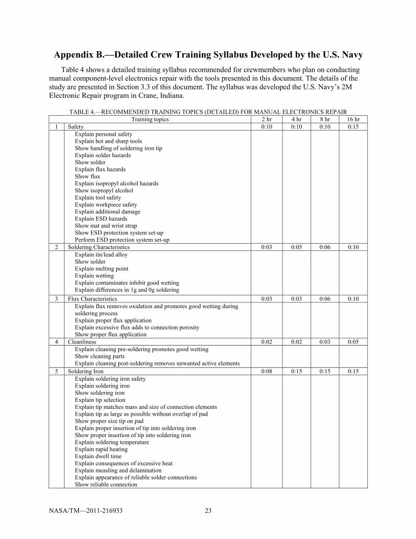
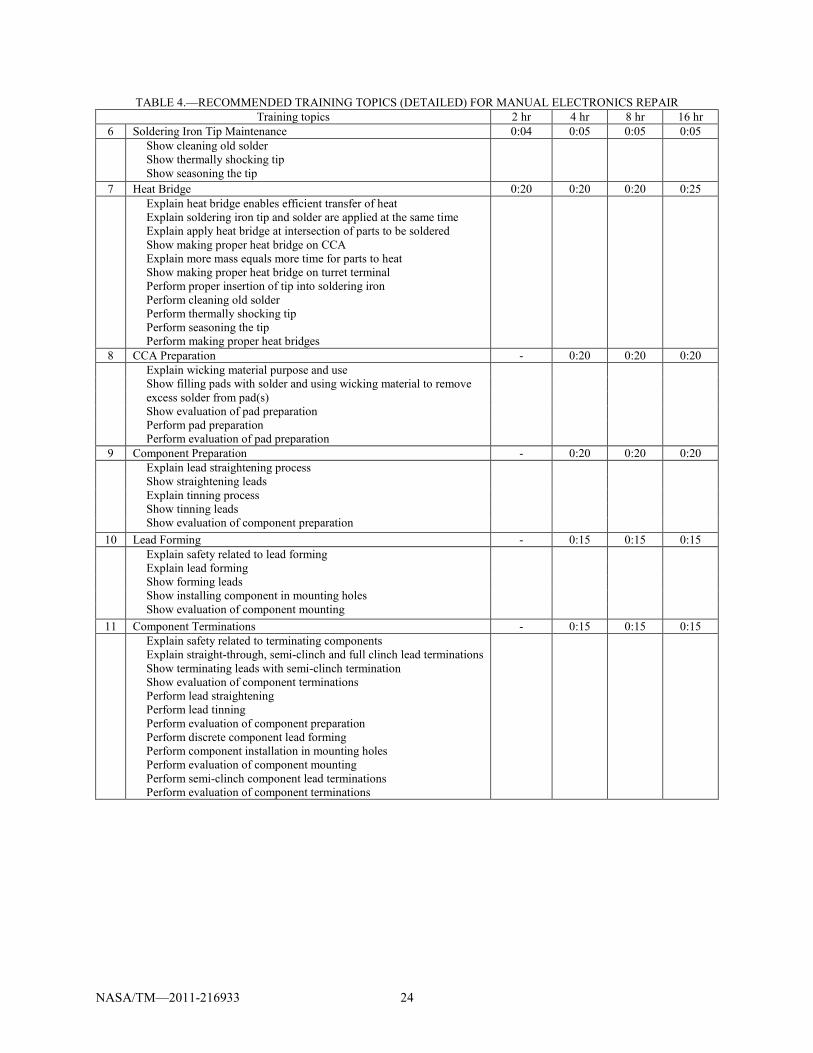
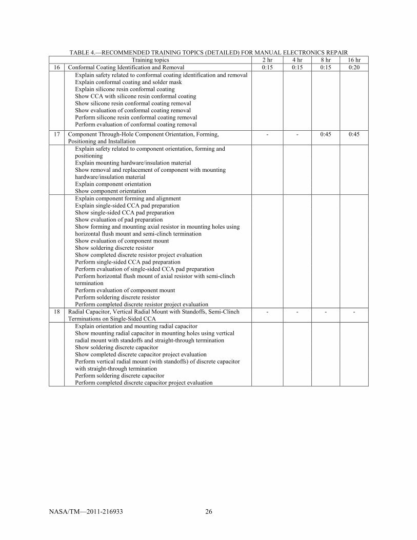
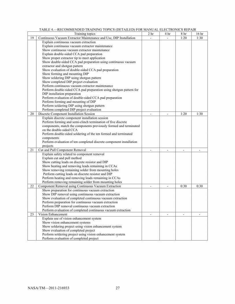
Appendix B.—Detailed Crew Training Syllabus Developed by the U.S. Navy Table 4 shows a detailed training syllabus recommended for crewmembers who plan on conducting
manual component-level electronics repair with the tools presented in this document. The details of the study are presented in Section 3.3 of this document. The syllabus was developed the U.S. Navy’s 2M Electronic Repair program in Crane, Indiana.
TABLE 4.—RECOMMENDED TRAINING TOPICS (DETAILED) FOR MANUAL ELECTRONICS REPAIR
Training topics 2 hr 4 hr 8 hr 16 hr 1 Safety 0:10 0:10 0:10 0:15 Explain personal safety
Explain hot and sharp tools Show handling of soldering iron tip Explain solder hazards Show solder Explain flux hazards Show flux Explain isopropyl alcohol hazards Show isopropyl alcohol Explain tool safety Explain workpiece safety Explain additional damage Explain ESD hazards Show mat and wrist strap Show ESD protection system set-up Perform ESD protection system set-up
2 Soldering Characteristics 0:03 0:05 0:06 0:10 Explain tin/lead alloy
Show solder Explain melting point Explain wetting Explain contaminates inhibit good wetting Explain differences in 1g and 0g soldering
3 Flux Characteristics 0:03 0:03 0:06 0:10 Explain flux removes oxidation and promotes good wetting during
soldering process Explain proper flux application Explain excessive flux adds to connection porosity Show proper flux application
4 Cleanliness 0:02 0:02 0:03 0:05 Explain cleaning pre-soldering promotes good wetting
Show cleaning parts Explain cleaning post-soldering removes unwanted active elements
5 Soldering Iron 0:08 0:15 0:15 0:15 Explain soldering iron safety
Explain soldering iron Show soldering iron Explain tip selection Explain tip matches mass and size of connection elements Explain tip as large as possible without overlap of pad Show proper size tip on pad Explain proper insertion of tip into soldering iron Show proper insertion of tip into soldering iron Explain soldering temperature Explain rapid heating Explain dwell time Explain consequences of excessive heat Explain measling and delamination Explain appearance of reliable solder connections Show reliable connection
NASA/TM—2011-216933 24
TABLE 4.—RECOMMENDED TRAINING TOPICS (DETAILED) FOR MANUAL ELECTRONICS REPAIR Training topics 2 hr 4 hr 8 hr 16 hr
6 Soldering Iron Tip Maintenance 0:04 0:05 0:05 0:05 Show cleaning old solder
Show thermally shocking tip Show seasoning the tip
7 Heat Bridge 0:20 0:20 0:20 0:25 Explain heat bridge enables efficient transfer of heat
Explain soldering iron tip and solder are applied at the same time Explain apply heat bridge at intersection of parts to be soldered Show making proper heat bridge on CCA Explain more mass equals more time for parts to heat Show making proper heat bridge on turret terminal Perform proper insertion of tip into soldering iron Perform cleaning old solder Perform thermally shocking tip Perform seasoning the tip Perform making proper heat bridges
8 CCA Preparation - 0:20 0:20 0:20 Explain wicking material purpose and use
Show filling pads with solder and using wicking material to remove excess solder from pad(s) Show evaluation of pad preparation Perform pad preparation Perform evaluation of pad preparation
9 Component Preparation - 0:20 0:20 0:20 Explain lead straightening process
Show straightening leads Explain tinning process Show tinning leads Show evaluation of component preparation
10 Lead Forming - 0:15 0:15 0:15 Explain safety related to lead forming
Explain lead forming Show forming leads Show installing component in mounting holes Show evaluation of component mounting
11 Component Terminations - 0:15 0:15 0:15 Explain safety related to terminating components
Explain straight-through, semi-clinch and full clinch lead terminations Show terminating leads with semi-clinch termination Show evaluation of component terminations Perform lead straightening Perform lead tinning Perform evaluation of component preparation Perform discrete component lead forming Perform component installation in mounting holes Perform evaluation of component mounting Perform semi-clinch component lead terminations Perform evaluation of component terminations

NASA/TM—2011-216933 25
TABLE 4.—RECOMMENDED TRAINING TOPICS (DETAILED) FOR MANUAL ELECTRONICS REPAIR Training topics 2 hr 4 hr 8 hr 16 hr
12 Solder Application and Post Solder Connection Cleaning - 0:35 0:35 0:45 Explain safety related to solder application
Explain proper heat bridge Explain forming fillets Show discrete component soldering Explain letting project cool Explain post solder connection cleaning Show cleaning project Explain appearance of reliable connection Explain appearance of defective connection Show evaluation of completed component installation Perform component soldering Perform cleaning of project Perform evaluation of completed component installation
13 Wire Stripping and Tinning 0:15 0:15 0:15 0:20 Explain wire stripping process Show stripping wire Explain tinning wire Show tinning wire Show evaluation of stripped and tinned wire Perform wire stripping Perform wire tinning Perform evaluation of stripped and tinned wire
14 Terminal Preparation 0:10 0:10 0:10 0:15 Explain safety related to terminal and wire preparation Show adding solder and using wicking material to remove excess
solder from terminal
Show evaluation of terminal preparation Perform terminal preparation Perform evaluation of terminal preparation
15 Wire Forming and Termination, Wire to Terminal Soldering 0:30 0:35 0:35 0:45 Explain safety related to wire forming Explain wire forming Show forming wire to terminal Explain wire termination Show terminating wire on terminal Show evaluation of wire forming and termination Explain safety related to solder application Explain proper heat bridge Show proper heat bridge Explain forming fillets Show turret terminal soldering Explain letting project cool Explain post solder connection cleaning Show cleaning project Show evaluation of completed turret terminal project Perform wire forming on terminal Perform wire termination on terminal Perform evaluation of wire forming and termination Perform wire to turret terminal soldering Perform cleaning of project Perform evaluation completed turret terminal project
NASA/TM—2011-216933 26
TABLE 4.—RECOMMENDED TRAINING TOPICS (DETAILED) FOR MANUAL ELECTRONICS REPAIR Training topics 2 hr 4 hr 8 hr 16 hr
16 Conformal Coating Identification and Removal 0:15 0:15 0:15 0:20 Explain safety related to conformal coating identification and removal
Explain conformal coating and solder mask Explain silicone resin conformal coating Show CCA with silicone resin conformal coating Show silicone resin conformal coating removal Show evaluation of conformal coating removal Perform silicone resin conformal coating removal Perform evaluation of conformal coating removal
17 Component Through-Hole Component Orientation, Forming, Positioning and Installation
- - 0:45 0:45
Explain safety related to component orientation, forming and positioning
Explain mounting hardware/insulation material Show removal and replacement of component with mounting
hardware/insulation material
Explain component orientation Show component orientation Explain component forming and alignment Explain single-sided CCA pad preparation Show single-sided CCA pad preparation Show evaluation of pad preparation Show forming and mounting axial resistor in mounting holes using
horizontal flush mount and semi-clinch termination
Show evaluation of component mount Show soldering discrete resistor Show completed discrete resistor project evaluation Perform single-sided CCA pad preparation Perform evaluation of single-sided CCA pad preparation Perform horizontal flush mount of axial resistor with semi-clinch
termination
Perform evaluation of component mount Perform soldering discrete resistor Perform completed discrete resistor project evaluation
18 Radial Capacitor, Vertical Radial Mount with Standoffs, Semi-Clinch Terminations on Single-Sided CCA
- - - -
Explain orientation and mounting radial capacitor Show mounting radial capacitor in mounting holes using vertical
radial mount with standoffs and straight-through termination
Show soldering discrete capacitor Show completed discrete capacitor project evaluation Perform vertical radial mount (with standoffs) of discrete capacitor
with straight-through termination
Perform soldering discrete capacitor Perform completed discrete capacitor project evaluation
NASA/TM—2011-216933 27
TABLE 4.—RECOMMENDED TRAINING TOPICS (DETAILED) FOR MANUAL ELECTRONICS REPAIR Training topics 2 hr 4 hr 8 hr 16 hr
19 Continuous Vacuum Extractor Maintenance and Use, DIP Installation - - 1:20 1:30 Explain continuous vacuum extraction
Explain continuous vacuum extractor maintenance Show continuous vacuum extractor maintenance Explain double-sided CCA pad preparation Show proper extractor tip to meet application Show double-sided CCA pad preparation using continuous vacuum extractor and shotgun pattern Show evaluation of double-sided CCA pad preparation Show forming and mounting DIP Show soldering DIP using shotgun pattern Show completed DIP project evaluation Perform continuous vacuum extractor maintenance Perform double-sided CCA pad preparation using shotgun pattern for DIP installation preparation Perform evaluation of double-sided CCA pad preparation Perform forming and mounting of DIP Perform soldering DIP using shotgun pattern Perform completed DIP project evaluation
20 Discrete Component Installation Session - - 1:20 1:30 Explain discrete component installation session Perform forming and semi-clinch termination of five discrete
components, match the components previously formed and terminated on the double-sided CCA
Perform double-sided soldering of the ten formed and terminated components
Perform evaluation of ten completed discrete component installation projects
21 Cut and Pull Component Removal - - - - Explain safety related to component removal Explain cut and pull method Show cutting leads on discrete resistor and DIP Show heating and removing leads remaining in CCAs Show removing remaining solder from mounting holes Perform cutting leads on discrete resistor and DIP Perform heating and removing leads remaining in CCAs Perform removing remaining solder from mounting holes
22 Component Removal using Continuous Vacuum Extraction - - 0:30 0:30 Show preparation for continuous vacuum extraction Show DIP removal using continuous vacuum extraction Show evaluation of completed continuous vacuum extraction Perform preparation for continuous vacuum extraction Perform DIP removal continuous vacuum extraction Perform evaluation of completed continuous vacuum extraction
23 Vision Enhancement - - - - Explain use of vision enhancement system Show vision enhancement systems Show soldering project using vision enhancement system Show evaluation of completed project Perform soldering project using vision enhancement system Perform evaluation of completed project
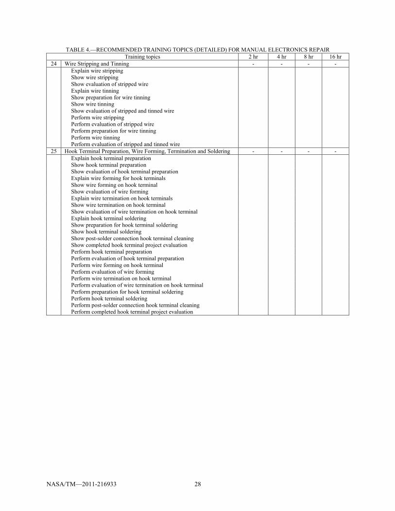
NASA/TM—2011-216933 28
TABLE 4.—RECOMMENDED TRAINING TOPICS (DETAILED) FOR MANUAL ELECTRONICS REPAIR Training topics 2 hr 4 hr 8 hr 16 hr
24 Wire Stripping and Tinning - - - - Explain wire stripping
Show wire stripping Show evaluation of stripped wire Explain wire tinning Show preparation for wire tinning Show wire tinning Show evaluation of stripped and tinned wire Perform wire stripping Perform evaluation of stripped wire Perform preparation for wire tinning Perform wire tinning Perform evaluation of stripped and tinned wire
25 Hook Terminal Preparation, Wire Forming, Termination and Soldering - - - - Explain hook terminal preparation Show hook terminal preparation Show evaluation of hook terminal preparation Explain wire forming for hook terminals Show wire forming on hook terminal Show evaluation of wire forming Explain wire termination on hook terminals Show wire termination on hook terminal Show evaluation of wire termination on hook terminal Explain hook terminal soldering Show preparation for hook terminal soldering Show hook terminal soldering Show post-solder connection hook terminal cleaning Show completed hook terminal project evaluation Perform hook terminal preparation Perform evaluation of hook terminal preparation Perform wire forming on hook terminal Perform evaluation of wire forming Perform wire termination on hook terminal Perform evaluation of wire termination on hook terminal Perform preparation for hook terminal soldering Perform hook terminal soldering Perform post-solder connection hook terminal cleaning Perform completed hook terminal project evaluation
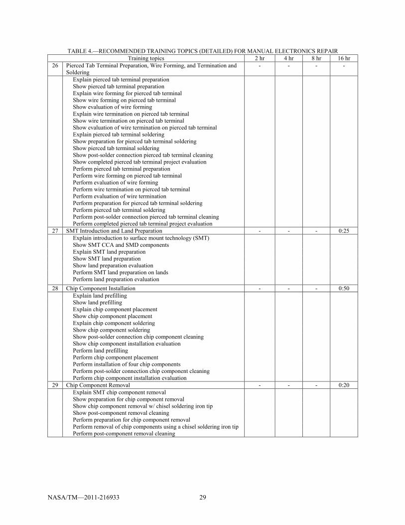
NASA/TM—2011-216933 29
TABLE 4.—RECOMMENDED TRAINING TOPICS (DETAILED) FOR MANUAL ELECTRONICS REPAIR Training topics 2 hr 4 hr 8 hr 16 hr
26 Pierced Tab Terminal Preparation, Wire Forming, and Termination and Soldering
- - - -
Explain pierced tab terminal preparation Show pierced tab terminal preparation Explain wire forming for pierced tab terminal Show wire forming on pierced tab terminal Show evaluation of wire forming Explain wire termination on pierced tab terminal Show wire termination on pierced tab terminal Show evaluation of wire termination on pierced tab terminal Explain pierced tab terminal soldering Show preparation for pierced tab terminal soldering Show pierced tab terminal soldering Show post-solder connection pierced tab terminal cleaning Show completed pierced tab terminal project evaluation Perform pierced tab terminal preparation Perform wire forming on pierced tab terminal Perform evaluation of wire forming Perform wire termination on pierced tab terminal Perform evaluation of wire termination Perform preparation for pierced tab terminal soldering Perform pierced tab terminal soldering Perform post-solder connection pierced tab terminal cleaning Perform completed pierced tab terminal project evaluation
27 SMT Introduction and Land Preparation - - - 0:25 Explain introduction to surface mount technology (SMT)
Show SMT CCA and SMD components Explain SMT land preparation Show SMT land preparation Show land preparation evaluation Perform SMT land preparation on lands Perform land preparation evaluation
28 Chip Component Installation - - - 0:50 Explain land prefilling Show land prefilling Explain chip component placement Show chip component placement Explain chip component soldering Show chip component soldering Show post-solder connection chip component cleaning Show chip component installation evaluation Perform land prefilling Perform chip component placement Perform installation of four chip components Perform post-solder connection chip component cleaning Perform chip component installation evaluation
29 Chip Component Removal - - - 0:20 Explain SMT chip component removal Show preparation for chip component removal Show chip component removal w/ chisel soldering iron tip Show post-component removal cleaning Perform preparation for chip component removal Perform removal of chip components using a chisel soldering iron tip Perform post-component removal cleaning
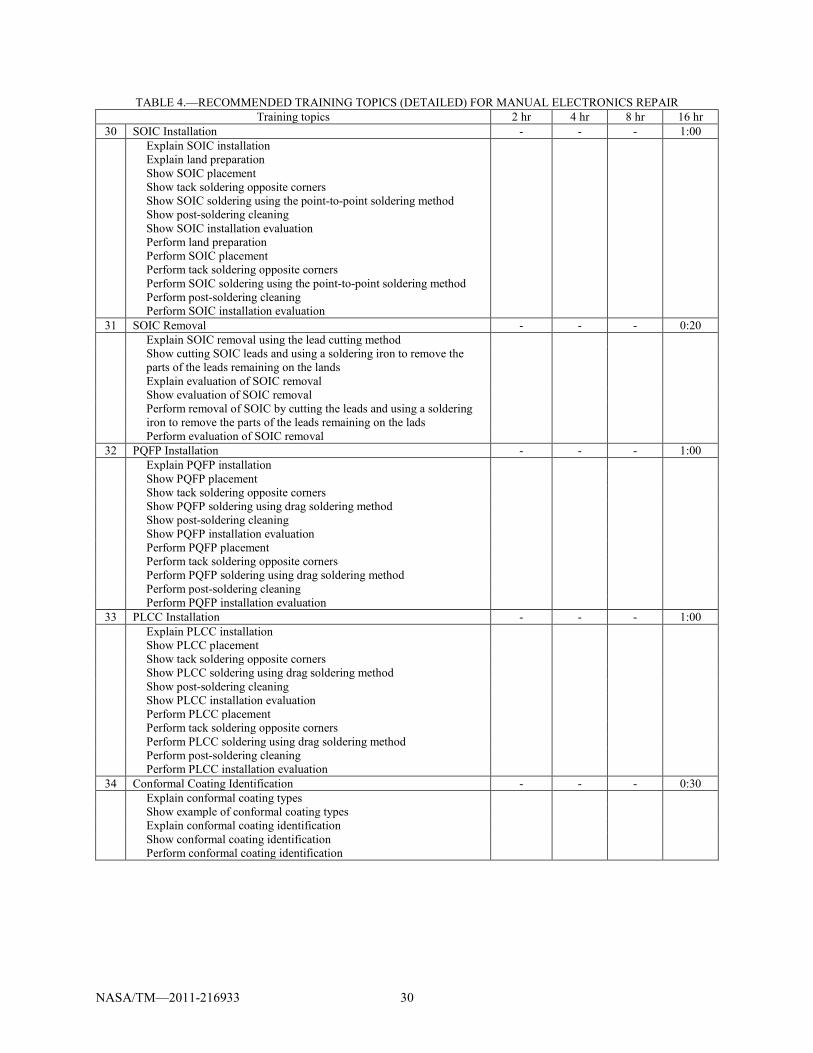
NASA/TM—2011-216933 30
TABLE 4.—RECOMMENDED TRAINING TOPICS (DETAILED) FOR MANUAL ELECTRONICS REPAIR Training topics 2 hr 4 hr 8 hr 16 hr
30 SOIC Installation - - - 1:00 Explain SOIC installation
Explain land preparation Show SOIC placement Show tack soldering opposite corners Show SOIC soldering using the point-to-point soldering method Show post-soldering cleaning Show SOIC installation evaluation Perform land preparation Perform SOIC placement Perform tack soldering opposite corners Perform SOIC soldering using the point-to-point soldering method Perform post-soldering cleaning Perform SOIC installation evaluation
31 SOIC Removal - - - 0:20 Explain SOIC removal using the lead cutting method Show cutting SOIC leads and using a soldering iron to remove the
parts of the leads remaining on the lands
Explain evaluation of SOIC removal Show evaluation of SOIC removal Perform removal of SOIC by cutting the leads and using a soldering
iron to remove the parts of the leads remaining on the lads
Perform evaluation of SOIC removal 32 PQFP Installation - - - 1:00 Explain PQFP installation Show PQFP placement Show tack soldering opposite corners Show PQFP soldering using drag soldering method Show post-soldering cleaning Show PQFP installation evaluation Perform PQFP placement Perform tack soldering opposite corners Perform PQFP soldering using drag soldering method Perform post-soldering cleaning Perform PQFP installation evaluation
33 PLCC Installation - - - 1:00 Explain PLCC installation Show PLCC placement Show tack soldering opposite corners Show PLCC soldering using drag soldering method Show post-soldering cleaning Show PLCC installation evaluation Perform PLCC placement Perform tack soldering opposite corners Perform PLCC soldering using drag soldering method Perform post-soldering cleaning Perform PLCC installation evaluation
34 Conformal Coating Identification - - - 0:30 Explain conformal coating types Show example of conformal coating types Explain conformal coating identification Show conformal coating identification Perform conformal coating identification
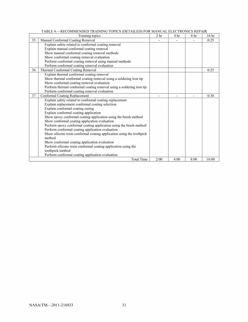
NASA/TM—2011-216933 31
TABLE 4.—RECOMMENDED TRAINING TOPICS (DETAILED) FOR MANUAL ELECTRONICS REPAIR Training topics 2 hr 4 hr 8 hr 16 hr
35 Manual Conformal Coating Removal - - - 0:25 Explain safety related to conformal coating removal
Explain manual conformal coating removal Show manual conformal coating removal methods Show conformal coating removal evaluation Perform conformal coating removal using manual methods Perform conformal coating removal evaluation
36 Thermal Conformal Coating Removal 0:25 Explain thermal conformal coating removal Show thermal conformal coating removal using a soldering iron tip Show conformal coating removal evaluation Perform thermal conformal coating removal using a soldering iron tip Perform conformal coating removal evaluation
37 Conformal Coating Replacement - - - 0:30 Explain safety related to conformal coating replacement Explain replacement conformal coating selection Explain conformal coating curing Explain conformal coating application Show epoxy conformal coating application using the brush method Show conformal coating application evaluation Perform epoxy conformal coating application using the brush method Perform conformal coating application evaluation Show silicone resin conformal coating application using the toothpick
method
Show conformal coating application evaluation Perform silicone resin conformal coating application using the
toothpick method
Perform conformal coating application evaluation Total Time 2:00 4:00 8:00 16:00
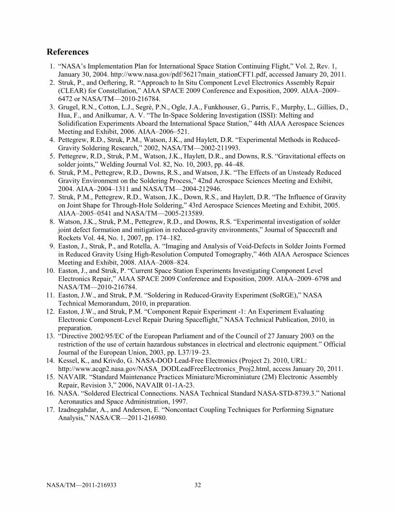
NASA/TM—2011-216933 32
References 1. “NASA’s Implementation Plan for International Space Station Continuing Flight,” Vol. 2, Rev. 1,
January 30, 2004. http://www.nasa.gov/pdf/56217main_stationCFT1.pdf, accessed January 20, 2011. 2. Struk, P., and Oeftering, R. “Approach to In Situ Component Level Electronics Assembly Repair
(CLEAR) for Constellation,” AIAA SPACE 2009 Conference and Exposition, 2009. AIAA–2009–6472 or NASA/TM—2010-216784.
3. Grugel, R.N., Cotton, L.J., Segrè, P.N., Ogle, J.A., Funkhouser, G., Parris, F., Murphy, L., Gillies, D., Hua, F., and Anilkumar, A. V. “The In-Space Soldering Investigation (ISSI): Melting and Solidification Experiments Aboard the International Space Station,” 44th AIAA Aerospace Sciences Meeting and Exhibit, 2006. AIAA–2006–521.
4. Pettegrew, R.D., Struk, P.M., Watson, J.K., and Haylett, D.R. “Experimental Methods in Reduced-Gravity Soldering Research,” 2002, NASA/TM—2002-211993.
5. Pettegrew, R.D., Struk, P.M., Watson, J.K., Haylett, D.R., and Downs, R.S. “Gravitational effects on solder joints,” Welding Journal Vol. 82, No. 10, 2003, pp. 44–48.
6. Struk, P.M., Pettegrew, R.D., Downs, R.S., and Watson, J.K. “The Effects of an Unsteady Reduced Gravity Environment on the Soldering Process,” 42nd Aerospace Sciences Meeting and Exhibit, 2004. AIAA–2004–1311 and NASA/TM—2004-212946.
7. Struk, P.M., Pettegrew, R.D., Watson, J.K., Down, R.S., and Haylett, D.R. “The Influence of Gravity on Joint Shape for Through-Hole Soldering,” 43rd Aerospace Sciences Meeting and Exhibit, 2005. AIAA–2005–0541 and NASA/TM—2005-213589.
8. Watson, J.K., Struk, P.M., Pettegrew, R.D., and Downs, R.S. “Experimental investigation of solder joint defect formation and mitigation in reduced-gravity environments,” Journal of Spacecraft and Rockets Vol. 44, No. 1, 2007, pp. 174–182.
9. Easton, J., Struk, P., and Rotella, A. “Imaging and Analysis of Void-Defects in Solder Joints Formed in Reduced Gravity Using High-Resolution Computed Tomography,” 46th AIAA Aerospace Sciences Meeting and Exhibit, 2008. AIAA–2008–824.
10. Easton, J., and Struk, P. “Current Space Station Experiments Investigating Component Level Electronics Repair,” AIAA SPACE 2009 Conference and Exposition, 2009. AIAA–2009–6798 and NASA/TM—2010-216784.
11. Easton, J.W., and Struk, P.M. “Soldering in Reduced-Gravity Experiment (SoRGE),” NASA Technical Memorandum, 2010, in preparation.
12. Easton, J.W., and Struk, P.M. “Component Repair Experiment -1: An Experiment Evaluating Electronic Component-Level Repair During Spaceflight,” NASA Technical Publication, 2010, in preparation.
13. “Directive 2002/95/EC of the European Parliament and of the Council of 27 January 2003 on the restriction of the use of certain hazardous substances in electrical and electronic equipment.” Official Journal of the European Union, 2003, pp. L37/19–23.
14. Kessel, K., and Krivdo, G. NASA-DOD Lead-Free Electronics (Project 2). 2010, URL: http://www.acqp2.nasa.gov/NASA_DODLeadFreeElectronics_Proj2.html, access January 20, 2011.
15. NAVAIR. “Standard Maintenance Practices Miniature/Microminiature (2M) Electronic Assembly Repair, Revision 3,” 2006, NAVAIR 01-1A-23.
16. NASA. “Soldered Electrical Connections. NASA Technical Standard NASA-STD-8739.3.” National Aeronautics and Space Administration, 1997.
17. Izadnegahdar, A., and Anderson, E. “Noncontact Coupling Techniques for Performing Signature Analysis,” NASA/CR—2011-216980.
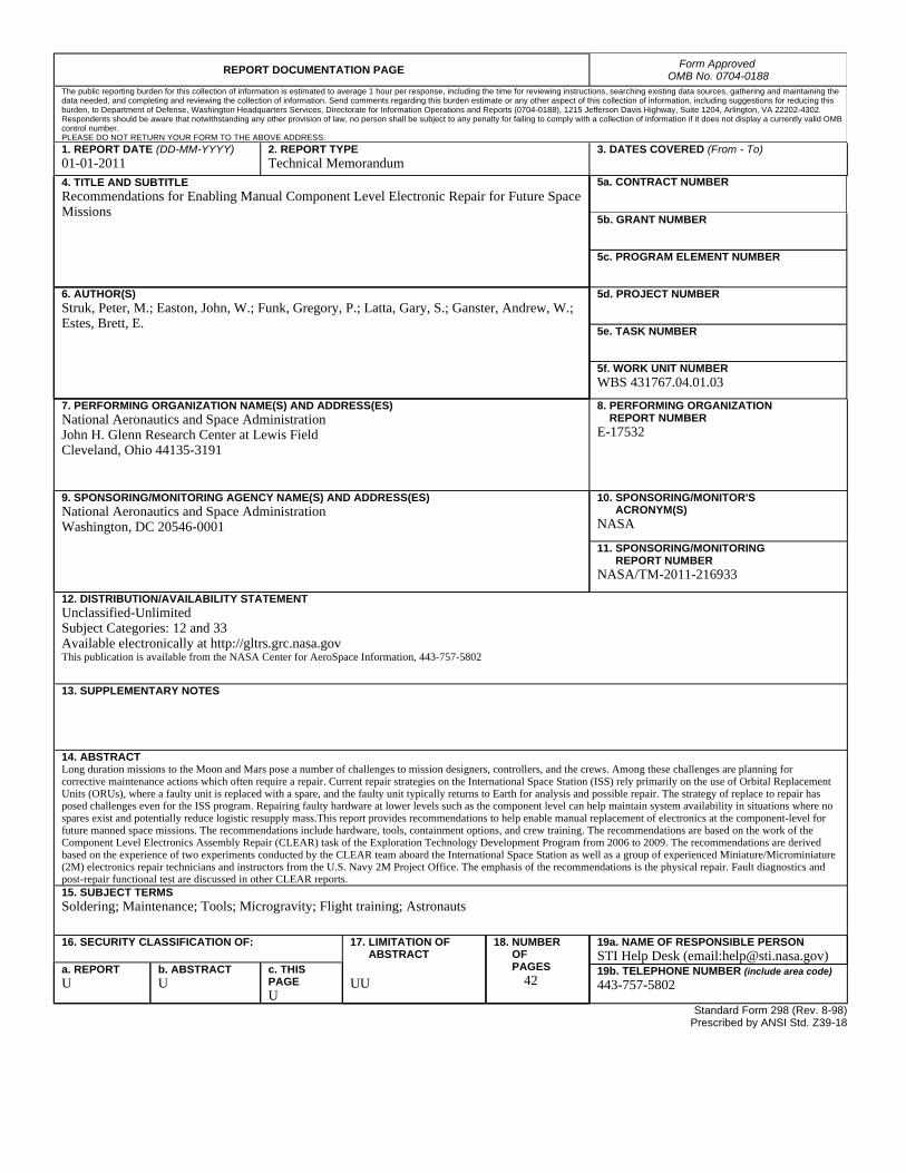
REPORT DOCUMENTATION PAGE Form Approved
OMB No. 0704-0188 The public reporting burden for this collection of information is estimated to average 1 hour per response, including the time for reviewing instructions, searching existing data sources, gathering and maintaining the data needed, and completing and reviewing the collection of information. Send comments regarding this burden estimate or any other aspect of this collection of information, including suggestions for reducing this burden, to Department of Defense, Washington Headquarters Services, Directorate for Information Operations and Reports (0704-0188), 1215 Jefferson Davis Highway, Suite 1204, Arlington, VA 22202-4302. Respondents should be aware that notwithstanding any other provision of law, no person shall be subject to any penalty for failing to comply with a collection of information if it does not display a currently valid OMB control number. PLEASE DO NOT RETURN YOUR FORM TO THE ABOVE ADDRESS.
1. REPORT DATE (DD-MM-YYYY) 01-01-2011
2. REPORT TYPE Technical Memorandum
3. DATES COVERED (From - To)
4. TITLE AND SUBTITLE Recommendations for Enabling Manual Component Level Electronic Repair for Future Space Missions
5a. CONTRACT NUMBER
5b. GRANT NUMBER
5c. PROGRAM ELEMENT NUMBER
6. AUTHOR(S) Struk, Peter, M.; Easton, John, W.; Funk, Gregory, P.; Latta, Gary, S.; Ganster, Andrew, W.; Estes, Brett, E.
5d. PROJECT NUMBER
5e. TASK NUMBER
5f. WORK UNIT NUMBER WBS 431767.04.01.03
7. PERFORMING ORGANIZATION NAME(S) AND ADDRESS(ES) National Aeronautics and Space Administration John H. Glenn Research Center at Lewis Field Cleveland, Ohio 44135-3191
8. PERFORMING ORGANIZATION REPORT NUMBER E-17532
9. SPONSORING/MONITORING AGENCY NAME(S) AND ADDRESS(ES) National Aeronautics and Space Administration Washington, DC 20546-0001
10. SPONSORING/MONITOR'S ACRONYM(S) NASA
11. SPONSORING/MONITORING REPORT NUMBER NASA/TM-2011-216933
12. DISTRIBUTION/AVAILABILITY STATEMENT Unclassified-Unlimited Subject Categories: 12 and 33 Available electronically at http://gltrs.grc.nasa.gov This publication is available from the NASA Center for AeroSpace Information, 443-757-5802
13. SUPPLEMENTARY NOTES
14. ABSTRACT Long duration missions to the Moon and Mars pose a number of challenges to mission designers, controllers, and the crews. Among these challenges are planning for corrective maintenance actions which often require a repair. Current repair strategies on the International Space Station (ISS) rely primarily on the use of Orbital Replacement Units (ORUs), where a faulty unit is replaced with a spare, and the faulty unit typically returns to Earth for analysis and possible repair. The strategy of replace to repair has posed challenges even for the ISS program. Repairing faulty hardware at lower levels such as the component level can help maintain system availability in situations where no spares exist and potentially reduce logistic resupply mass.This report provides recommendations to help enable manual replacement of electronics at the component-level for future manned space missions. The recommendations include hardware, tools, containment options, and crew training. The recommendations are based on the work of the Component Level Electronics Assembly Repair (CLEAR) task of the Exploration Technology Development Program from 2006 to 2009. The recommendations are derived based on the experience of two experiments conducted by the CLEAR team aboard the International Space Station as well as a group of experienced Miniature/Microminiature (2M) electronics repair technicians and instructors from the U.S. Navy 2M Project Office. The emphasis of the recommendations is the physical repair. Fault diagnostics and post-repair functional test are discussed in other CLEAR reports. 15. SUBJECT TERMS Soldering; Maintenance; Tools; Microgravity; Flight training; Astronauts
16. SECURITY CLASSIFICATION OF: 17. LIMITATION OF ABSTRACT UU
18. NUMBER OF PAGES
42
19a. NAME OF RESPONSIBLE PERSON STI Help Desk (email:[email protected])
a. REPORT U
b. ABSTRACT U
c. THIS PAGE U
19b. TELEPHONE NUMBER (include area code) 443-757-5802
Standard Form 298 (Rev. 8-98)Prescribed by ANSI Std. Z39-18

