recommendations for harmonic and power measurements in ... · • active power • reactive power...
TRANSCRIPT
Recommendations for Harmonic and Power
Measurements in Electrical Networks
Analysis implementation and reporting requirements regarding grid power quality and equipment loads
Power Capacitor Division

Recommendations for Harmonic and Power Measurements in Electrical Networks
Published by:ZVEI - Zentralverband ElektrotechnikundElektronikindustrie e. V.German Electrical and ElectronicManufacturers’ AssociationPower Capacitors Division– Power Capacitors and Power Quality Department Lyoner Strasse 960528 Frankfurt am Main, Germany
Editor:Dr. Marcus DietrichPhone: +49 69 6302-462Fax: +49 69 6302-407E-Mail: [email protected]
September 2018
www.zvei.org
BY NC SA
This work is licensed under the Creative Commons Attribution-Non- Commercial-Share Alike 4.0 Germany.
Despite utmost care for the content no liability will be accepted.
Authors: Dr. Christian Dresel, Jürgen Reese, Dieter Siebold, Condensator DominitLukas Motta, EpcosPeter Riese, FrakoDr. Christian Kaehler, Hans von MangoldtAchim Tempelmeier, KBR KompensationsanlagenbauDr. Bernd Walther, Maschinenfabrik Reinhausen – Power QualityAlexander Heinz, System Electric Power QualityChristophe Durandet, Vishay Electronic
3
IntroductionGermany has one of the world’s most reliable networks when it comes to the supply of
electrical power. But high service reliability is not necessarily synonymous with high power
quality, which is affected by deviations in network voltage from the purely sinusoidal
waveform or network voltage fluctuations.
Ensuring the supply of power in sufficient quality therefore plays a major role in industrial
and increasingly also in public distribution networks.
The number and variety of electronic power converters has significantly increased in recent
years – from switched-mode power supply to powerful rolling mill drives. In addition, new
HVDC lines are being used, both on the mainland and for connecting offshore wind farms.
Consequently, power electronics account for a large proportion of all electrical energy
generated and consumed.
Today, power quality measurements have become an essential tool for operating and/or
designing power grids.
These recommendations are intended to establish minimum requirements for technical
reports dealing with the measurement and analysis of power quality and power rating.
Power Quality
The term power quality is often used to describe the different types of disturbances that
affect the quality of supply such as:
• Harmonics up to 2.5 kHz in the supply voltage and/or supply current
• Rapid voltage changes (e.g. flicker) as well as slow voltage changes and voltage band
violations
• Commutation notches, which are sometimes only discernible together with cable
resonance oscillations
• Interharmonic voltages and currents up to 2.0 kHz and supraharmonic voltages and
currents (> 2.0 kHz)
• Current and voltage imbalances
• Audio frequency signals
Power Components
When measuring the power quality, it is necessary to differentiate between the fundamen-
tal frequency component (e.g. 50 Hz in Germany) and higher harmonic components or
other loads caused by imbalance or modulation such as
• Active power
• Reactive power caused by displacement
• Reactive power caused by distortion
• Reactive power caused by imbalance /modulation
• Reactive power (includes all of the above forms of reactive power and is always positive)
• Fundamental frequency
• Apparent power taking into account all of the power components
• Power factor λ• Displacement power factor cos φ

4
A 10-minute interval should be selected in order to evaluate the recorded harmonics.
Modern measurement instruments often also provide the option to map additional
intervals.
In many cases, it is necessary to analyse the 10-minute mean values to check for the
presence of highly dynamic events in the electrical network. For this reason, measurement
instruments provide aggregated data for 10 and/or 200 ms periods, depending on the type
of device, which must be evaluated with regard to it’s impact on the power quality.
Evaluation Basis
Power quality and power component ratio measurements are usually analysed according to
the following standards or guidelines:
• IEC6100 for power quality limits in public and industrial medium and low-voltage power
supply systems (voltages only)
• EN 50160 for public grids supplying high, medium and low voltage (voltages only)
• D-A-CH-CZ Technical Rules for the Assessment of Network Disturbances
• (voltages and currents)
• VDE application guides 41XX for high, medium and low voltage (voltages only)
• IEC 60871 for HV power capacitors
• IEC 60831 for LV power capacitors
• DIN EN 61800 for variable speed drives
• Other global standards: IEEE 519, GB/T 15543, GOST 13109, Engineering Recommenda-
tion G5/4-1 and P28
• Network connection contract detailing the displacement power factor cos φ and other
conditions agreed
According to the relevant standard, the measured values must meet the limit values during
95 or 100 percent of the measurement time (usually one week).
Tasks
The following information must be recorded in the final report after measuring the power
quality of an electrical network:
• Exact name of the company, location and station
• Measurement reason (routine check, disturbance, basis for network expansion or plant
design)
• Exact measurement period
• Circuit diagram (simplified or detailed) specifying the measuring point and switching
state
• Load conditions (normal load or deviating conditions)
• Exposed consumer (e.g. drive converter or welding machines) specifying data and
optionally the load profile
• Compensation equipment and relevant switching states
• Power filters
• Power generation equipment and emergency power systems
• Measurement analysis basis (standards, guidelines)
• Who performed the measurement
• Name of distribution network operator
5
Suitability of Measurement Equipment
It is essential to hold a technical meeting with the customer to determine the boundary
conditions for the necessary measurement. Based on the outcome of the meeting, conclu-
sions can be drawn about the measurement equipment to be used.
A distinction must be made between simple measurement tasks with measurement instru-
ments for recording statistical data and measurements for technically demanding network
analyses with instruments that have a frequency resolution from 20 to 150 kHz and can
record triggerable faults. This is particularly important for the latest generation of convert-
ers and network resonances due the instruments’ capacities (e.g. non-detuned compensa-
tion, input filters, power cables).
Power quality measurementsFor power quality measurements, type A instruments as defined in IEC 61000-4-30 must
be used. This ensures that the measurement results comply with relevant standards and are
suitable for unrestricted use. To evaluate the connection point in public grids, a 10-minute
time interval should be selected for the measurement. For analysing the load behaviour,
this interval can be reduced or oscillograms can be created e.g. to determine commutation
notches.
To determine the correct flicker values, the relevant nominal mains voltage must be indi-
cated in the measurement parameters.
Audio frequency signalsPrior to setting the measurement parameters, it is necessary to find out and enter the audio
frequency signals used in the network from the customer or distribution network operator.
The frequency and signal level are important when it comes to defining measures as part
of the necessary reduction of harmonics.
Current measurementsCurrents can be measured with split-core current transformers or Rogowski coils,
observing the transformation ratio and phase angle with regard to the relevant voltage.
If the instrument features a phasor diagram, this should be used to avoid measuring
errors. Modern measuring instruments also offer possibilities for data post-processing if
faulty parameter settings are identified.
Power measurementsIn many cases, a measurement with time resolution should be selected for power measure-
ments that corresponds to a counter sampling rate of 15 minutes.
Note that the transmission behaviour of the voltage transformers must be taken into
account, especially in medium and high-voltage networks. Depending on the trans-
former, significant distortions of measured values may occur from 1.0 kHz due to internal
resonances in the inductive transformer.
Today, power electronic devices that generate even harmonics and interharmonics are
increasingly used. For this reason, the relevant analysis modes of the measuring instru-
ments must be evaluated and, if necessary, presented in the report. The accuracy of the
measured results should always be assessed before or after the measurements, taking

6
into account the accuracy class, the converter and technical data of the measurement
instruments. The physical position of the Rogowski coils, for example, also greatly affects
the accuracy and can account for 20 percent of the errors.
Measurement Implementation
Before commencing with the measurement, the utility operator must determine the required
load variations or switching states, which must be documented by the network operator if
this information is not clearly evident from the measurement results.
The duration of the measurements can also be derived from these measures, which should
normally cover all load conditions. Only then can appropriate measures be derived for
the operational management of a network - for example, if limit values of standards are
reached or exceeded.
Triggers for switching operations or load changes may be required for measurements of
random disturbances.
For longer, unsupervised measurements, only approved equipment, measuring leads and
adapters are to be used to prevent personal injury.
Type of Report and Recommendations
There are two possibilities for creating technical reports that map measurement results:
• Executive summary with selected measurement results
• Comprehensive report with a theoretical section (explaining occurring stress phenomena
such as flicker, harmonics, voltage dips), a section describing the measurements and
several attachments for the relevant measurement points.
In both cases, care should be taken to ensure that the measurements are evaluated with
regard to compliance with the standards or specifications of the network operator. Thus the
person commissioning the network analysis, who is often not a proven expert in the field
of power quality, is given the opportunity to evaluate the measurements performed and to
draw conclusions for the operation of his/her electrical network.
If limit values are exceeded, e.g. harmonics, flicker (rapid voltage fluctuations) and
reactive power, the report should always contain recommendations for remedial measures
to be taken by network operators and consumers:
• Increasing the short-circuit power by changing the transformer power or increasing the
grid connection capacity
• Changing the pulse rate of power converter systems
• Changing switching from diode to active front end on the mains side
• Capacitive compensation systems with contactor control or low voltage semiconductor
switches for high load dynamics, and sometimes also inductive systems
• Passive filter circuits (capacitive reactive power must be observed)
• Active power filters
• Dynamic STATCOM systems that can generate inductive and capacitive reactive power
7
It is also necessary to respond to future grid changes in the customer network (increase
in power, increased connection of inverters etc.). However, the recommendations should
primarily provide an objective description of the effectiveness of the relevant mains-side or
consumer-side measures as well as economic aspects such as power loss while maintaining
a vendor-neutral position.
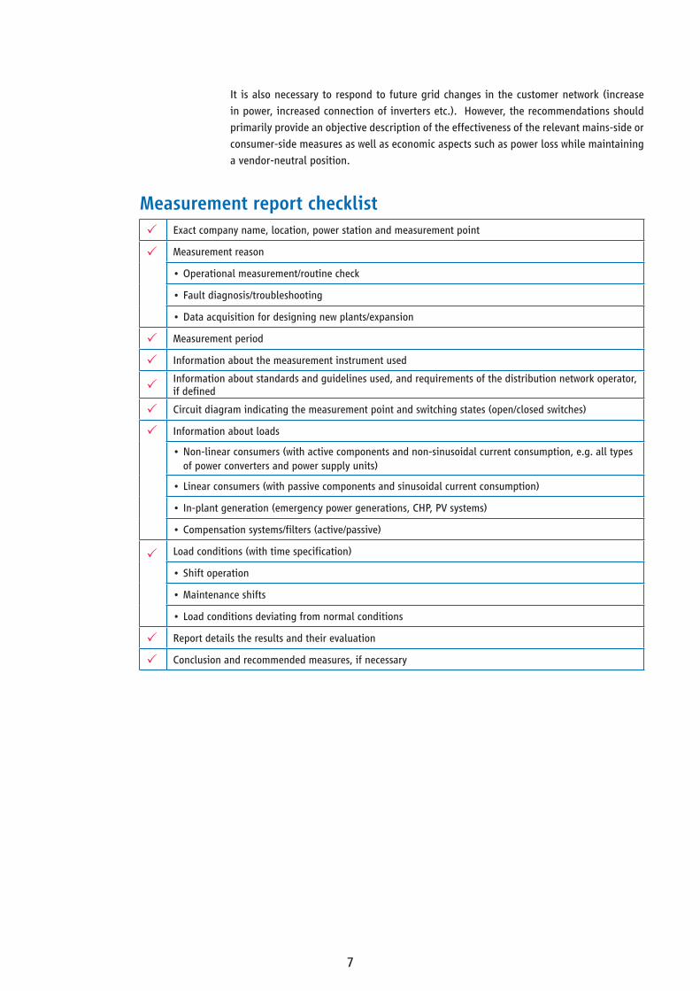
Measurement report checklist Exact company name, location, power station and measurement point
Measurement reason
•Operational measurement/routine check
•Fault diagnosis/troubleshooting
•Data acquisition for designing new plants/expansion
Measurement period
Information about the measurement instrument used
Information about standards and guidelines used, and requirements of the distribution network operator, if defined
Circuit diagram indicating the measurement point and switching states (open/closed switches)
Information about loads
•Non-linear consumers (with active components and non-sinusoidal current consumption, e.g. all types of power converters and power supply units)
•Linear consumers (with passive components and sinusoidal current consumption)
•In-plant generation (emergency power generations, CHP, PV systems)
•Compensation systems/filters (active/passive)
Load conditions (with time specification)
•Shift operation
•Maintenance shifts
•Load conditions deviating from normal conditions
Report details the results and their evaluation
Conclusion and recommended measures, if necessary

VEI - German Electrical and Electronic Manufacturers’ AssociationLyoner Straße 960528 Frankfurt am Main
Phone: +49 69 6302-0Fax: +49 69 6302-317E-Mail: [email protected]
Cred
it C
over
: Mas
chin
enfa
brik
Rei
nhau
sen
– Po
wer
Qua
lity