recommended practices for enhancing digital audio ...hgs/audio/dvi/ima_adpcm.pdfdatwg recommendation...
TRANSCRIPT

DATWG Recommendation Page 1 of 40 21 Oct 1992
Recommended Practices
for Enhancing Digital Audio Compatibility
in Multimedia Systems
by the IMA Digital Audio Focus and Technical Working Groups
Revision 3.00
21 October 1992
DATWG Recommendation Page 2 of 40 21 Oct 1992
Contents
Overview.................................................................................................................... 3Recommendation...................................................................................................... 4
Digital Audio Data Types ...................................................................................................... 4Digital Audio Sampling Rates ............................................................................................... 5Recommended Digital Audio Interchange Formats............................................................... 5Digital Audio Format Conversion.......................................................................................... 5
Appendix A: Data Type, Sample Rate, and Stream Definition .............................. 6Data Type Definitions............................................................................................................ 6
8-bit A-law, µ-law, mono................................................................................................... 68-bit linear, unsigned, mono and stereo............................................................................. 616-bit linear, signed, mono and stereo ............................................................................... 64-bit ADPCM..................................................................................................................... 6Stereo Formats ................................................................................................................... 6
Sample Rate Definitions ........................................................................................................ 7Note........................................................................................................................................ 7
Appendix B: Audio Algorithm Requirements:........................................................ 8Uncompressed Audio Format Requirements: ........................................................................ 8Audio Compression and Decompression Algorithm Requirements: ..................................... 8Compressed Audio Metrics:................................................................................................... 9
Appendix C: Questions and Answers................................................................... 10Appendix D: Reference Algorithms....................................................................... 11
Reference Algorithm Descriptions....................................................................................... 111. Conversion Algorithms Overview ............................................................................... 112. 16-bit/8-bit Conversion Overview ............................................................................... 12
2.1. 8-bit to 16-bit Conversion Algorithms ...................................................... 122.2. 16-bit to 8-bit Conversion Algorithms ...................................................... 13
3. 16-bit/µ-law Conversion Overview ............................................................................. 153.1. 16-bit Linear to µ-law Conversion ............................................................ 163.2. µ-law to 16-bit Linear Conversion ............................................................ 18
4. 16-bit/A-law Conversion Overview............................................................................. 204.1. 16-bit Linear to A-law Conversion ........................................................... 204.2. A-law to 16-bit Linear Conversion ........................................................... 22
5. Sample Rate Conversion (SRC) Overview.................................................................. 245.1. Integral Higher-to-Lower Sample Rate Conversion (Decimation) ........... 255.2. Integral Lower to Higher Sample Rate Conversion (Interpolation).......... 265.3. Non-integral Sample Rate Conversion (Interpolation and Decimation Together) .......................................................................................................... 27
6. ADPCM Reference Algorithms ................................................................................... 286.1. 16-bit Linear to 4-bit ADPCM Compression ............................................ 286.2. 4-bit ADPCM to 16-bit Linear Decompression ........................................ 31
Algorithm References............................................................................................. 33Reference Algorithm Code Listings...................................................................... 33Appendix E: Glossary............................................................................................. 34Appendix F: Development of the First Edition of the Digital Audio Recommended Practices ... 36

DATWG Recommendation Page 3 of 40 21 Oct 1992
OverviewThese recommended practices for developing and processing interchangeable digital audio data formats are presented by the Interactive Multimedia Association (IMA) to promote cross-platform digital audio compatibility. The convenient interchange of digital audio data is part of the IMA’s goal of encouraging multimedia application development.
The problems of interchange between PC, Macintosh, and workstation computers include different native audio data types and different sampling rates. In this document, format refers to a combination of sample data type and sampling rate. This document addresses those two interchange problems.
The IMA intends this document to be the first of a series of incremental recommendations on digital audio. This edition of the Recommended Practices is intended to specify:
a standard set of minimum capabilities that a platform vendor must support in order to create a compliant platform;
a standard set of digital audio sampling rates;
a standard set of formats for digital audio sample values;
a standard set of compression, decompression, format conversion, and sampling rate conversion algorithms.
This edition of the Recommendations is not intended to address any of the following issues:
signal stream formats: that is, issues having to do with blocking of data, embedding of synchronization information, algorithm state variable values, time stamps, etc.; blocking, multiplexing, or other organization of multiple streams of audio in time; or tagging of audio data with header format;
file format: specification of file or contain formats; merging of audio information with other media data or control information; standards for file labels or container structure, etc.
Upcoming editions of these Recommended Practices will add to the specifications in this first edition, and will address these and other issues. The intent is that these future editions will provide additional recommendations, rather than modify previous ones.
Appendix C addresses frequently asked questions regarding the Recommendation. A glossary is included as Appendix E.
These recommendations were initially developed by the Digital Audio Technical Working Group, and refined by the Digital Audio Focus Group of the IMA. Please see Appendix F for more information on these groups.

DATWG Recommendation Page 4 of 40 21 Oct 1992
Recommendation
The IMA feels the best way to encourage cross platform exchange of digital audio information is to define a limited set of audio formats that are guaranteed to be supported on any IMA audio compliant platform. These formats are required to provide baseline digital audio cross-platform support to satisfy a range of audio quality and data bandwidth requirements.
Three uncompressed and one compressed digital audio data types at four sampling rates are recommended as the minimum formats for IMA Cross-Platform Digital Audio Interchange. All of these formats should be supported by compliant platforms. A combination of already existing native audio hardware and a small amount of CPU utilization for conversion, using the algorithms documented here, will make this a reality.
To be compliant, a platform must be able to record one of the specified formats in real-time. It must be able to play back all of the specified formats in real-time. In addition, the IMA recommends that compliant platforms provide means to convert from any standard format to any other. Format conversion, in general, does not have to be accomplished in real-time, but see below.
Note that these recommendations do not address the issue of the quality of the rendered audio signal generated by a platform during recording or playback. It is within the spirit of the recommended practices for a platform to convert a format that can not be directly rendered (played back) into one that can be directly rendered, but the platform must be capable of doing both the conversion and associated playback in real-time.
Digital Audio Data TypesThe problem of different data types has been addressed in the proposal by selecting a minimum set of three uncompressed and one compressed type. One uncompressed type, 8-bit companded (both µ-law and A-law) addresses the native format of many workstations and several industry products compatible with telephony standards. A second, 8-bit unsigned linear is a type used in the PC and Macintosh environment. A third uncompressed type is 16-bit signed linear that is the standard audio data type on CD and is emerging in the computer industry. The DVI® ADPCM algorithm was selected to provide a standard method to exchange high quality (16-bit signed linear) data at data rates one-half that of the uncompressed 8-bit data rates at a given sampling frequency. The IMA believes this 4-bit data type will give the author of multimedia audio data the most scaleability in terms of audio dynamic range and lowest data rate. This scaleability does come at the expense of some CPU utilization for decompression, however it allows the scaling of fidelity for different hardware capabilities with a single data stream. Machines with 16-bit playback hardware can recover the most dynamic range, followed by 8-bit companded and 8-bit linear. Appendix A includes definitions of these data types.

DATWG Recommendation Page 5 of 40 21 Oct 1992
Digital Audio Sampling RatesThe problem of different audio sampling rates has been addressed in the proposal by selecting a minimum set of four sampling rates. One sampling rate is the 8.0 kHz rate typically used with the 8-bit companded converters. A second sampling rate selected is the 11.025 kHz rate found in PC’s and the Macintosh. A third sampling rate selected is the 22.05 kHz rate also found in PC’s and the Macintosh. The fourth sampling rate selected is the 44.1 kHz rate used in audio CDs and various computers. Appendix A includes definitions of these sample rates, with tolerances.
Recommended Digital Audio Interchange FormatsA set of data types and sampling rates has been selected as standard interchange formats. A set of requirements for this selection is outlined in Appendix B.
Sampling Rate
Mono/Stereo
Data Format Notes
mono 8-bit µ-Law PCM CCITT G.711 Standard, Workstation support
mono 8-bit A-Law PCM CCITT G.711 Standard, Workstation support8.0 kHz
mono 4-bit ADPCM DVI® algorithm
m/s 8-bit Linear PCM Macintosh & MPC support11.025 kHz
m/s 4-bit ADPCM DVI® algorithm
m/s 8-bit Linear PCM Macintosh & MPC support22.05 kHz
m/s 4-bit ADPCM DVI® algorithm
m/s 16-bit Linear PCM (Least Significant Byte first)
m/s 16-bit Linear PCM (Most Significant Byte first)44.10 kHz
m/s 4-bit ADPCM DVI® algorithm
A more precise definition of these formats is found in Appendix A of this document.
Digital Audio Format ConversionEach of these formats was considered essential by the IMA and allows the exchanging of a native hardware audio format with another IMA compliant platform without data conversion at the source. Because the destination platform cannot be expected to be able to directly play the source data format or sample rate, the IMA created and tested standard algorithms that can be performed real-time on the main CPU to convert thedata format and sampling rate to a native format and sampling rate. These algorithms are published in Appendix D, and were tested during the audio compression selection process.
The IMA urges vendors to support conversion from any standard format to any other, but the lack of such support does not automatically render a system non-compliant.

DATWG Recommendation Page 6 of 40 21 Oct 1992
Appendix A: Data Type, Sample Rate,and Stream Definition
Data Type Definitions
8-bit A-law, µ-law, mono
Refer to the CCITT G.711 specification for the exact definition of both µ-law (pronounced mu-law) and A-law audio. A stereo version of this data type is not supported.
8-bit linear, unsigned, mono and stereo
This data type is an unsigned representation using 256 (48dB) discrete and equally divided steps. The value 00h represents the most negative audio signal level, while the value 0FFh represents the most positive. This data type is the same as defined in the Apple Macintosh and MPC environments. Treating this data type as a bit stream, more significant bits precede less significant bits.
16-bit linear, signed, mono and stereo
This data type is a 16-bit (96dB) signed representation with 65535 equally divided steps between minimum and maximum amplitude. The signed nature of this data type dictates that the value –32768 indicates the most negative audio signal level while 32767 is the most positive. This data type is used in consumer CD audio players and is also defined on several computing platforms. There are two variants of this data type. In one variant the most significant byte of the sample value precedes the least significant byte. In the other variant, the least significant byte precedes the most significant byte. Integer values are represented using two’s complement representation. Treating the least significant byte of these data types as a bit stream, more significant bits precede less significant bits. Treating the most significant byte of these data types as a bit stream, more significant bits precede less significant bits. The sign bit precedes all other bits in the most significant byte.
4-bit ADPCM
This data type is a sign-magnitude representation of the difference between audio samples, using an adaptive quantizer. The specific implementation of the quantizer adaptation using table-based lookup was offered by Intel/DVI® as an open standard for use by the IMA.
Stereo Formats
Within each sample, there may be left channel and right channel information. When this occurs, the left channel information always precedes the right channel information.
DATWG Recommendation Page 7 of 40 21 Oct 1992
Sample Rate DefinitionsThe sample, rates defined in the first section of this proposal (8.0 kHz, 11.025 kHz, 22.05 kHz, and 44.10 kHz) are nominal values. It will be up to the platform implementation to achieve the most accurate approximation of these sampling rates when handling the audio data types. Applications that synchronize audio with other media elements need to be aware of the existence of non-exact sampling rates. The possible accumulation of timing errors in playback systems fundamentally must be accommodated by a synchronization mechanism in the architecture. The spirit of the IMA is to embrace as much existing technology as possible. Therefore, although a specific tolerance band is not recommended at this time, frequency tolerances need to span as much current practice as possible.
Specifically, it is recommended that the tolerance band be large enough that equipment, common in the industry, running at the nominal rates of 22.254 kHz, 11.127 kHz, and 8.04 kHz are all properly embraced within the total tolerance build-up. For simplicity, this is preferred over specifically calling out these nominal rates in the table of “Recommended Digital Audio Interchange Formats”.
NoteThis Recommendation does not encompass the methodology for tagging the audio stream with data type and sample rate information, but expects these two attributes, and possibly stream length (number of samples), to be the minimum additional information to be specified elsewhere in the architecture.

DATWG Recommendation Page 8 of 40 21 Oct 1992
Appendix B: Audio Algorithm Requirements:
The IMA Digital Audio Technical Working Group of the Cross Platform Compatibility Project set the following requirements during the search for an industry standard uncompressed and audio compression and decompression algorithm that would be suitable for real-time audio data exchange across various platforms such as the PC, Macintosh and workstations.
This work group has selected a minimum number of uncompressed 8 bit and 16 bit digital audio data stream definitions based on the following requirements.
Uncompressed Audio Format Requirements: Public domain algorithm and stream format. No license fees or royalty associated with using the algorithm as published. Provide at least one native PC, Macintosh, and workstation audio format that
allows sender of data to avoid need for data conversion. Format must be convertible to any of the other uncompressed formats using only
main processor and software in real-time (386/20 used for CPU utilization criteria).
The IMA recognizes the significant advantages that digital audio compression provides to the problem of cross-platform audio interchange. Lower data rates (about 4 bits per sample), greater dynamic range (16 bits of uncompressed data) and scaleable quality and performance are all important advantages of audio compression algorithms. Below are the requirements used for the selection of an audio compression/ decompression algorithm. It is not the intention of the IMA to restrict the implementation of the algorithm to the main processor of a computer, rather the DATWG IMA believes that an implementation designer should have the freedom to offer scaleable audio capabilities to their customers. We desire to maximize the number of platforms capable of playing/recording/exchanging digital audio.
Audio Compression and Decompression Algorithm Requirements:
Public domain algorithm and stream format. Reference compression and decompression algorithms (pseudo-code or C) to
be published by the IMA if not already available in public domain. Compressed data stream definition may allow more sophisticated
compression algorithms to be used (scalability feature), however, published decompression algorithm must be able to play resulting data stream (compatibility requirement).
No license fees or royalty associated with using the algorithm as published. Real-time decompression must be achievable on PC or workstation CPU
(386/20 used for CPU utilization criteria). Scalability of decompression bandwidth, etc., to accommodate range of
processor capability is acceptable. Non Real-time compression acceptable, or scaleable real-time compression on
PC or workstation CPU. Applicable across multiple frequencies, especially 8.0, 11.025, 22.05, and
44.1 kHz. Low data storage overhead for minimum bits per audio sample. A data stream definition conducive to computer environments.

DATWG Recommendation Page 9 of 40 21 Oct 1992
The DATWG developed a set of metrics for selecting an audio compression algorithm. Several categories received both quantitative formulas and weighting and a couple of categories and 30% of the points were reserved for individual member discretion due to their market requirements. The points available for each algorithm under consideration was a maximum of 100, as described below:
Compressed Audio Metrics: Subjective Listening (30 points):
Eleven audio tracks ten seconds in length from the SQAM Test CD were compared (double blind) against the algorithms under evaluation. A five-point scale was used to rate each algorithm for each track and each of the four sampling rates (both DAT and cassette tapes were made available to ensure identical results for comparison):
5: indistinguishable from original4: perceptible difference, but not annoying3: slightly annoying2: annoying1: very annoying
Score sheets were used to send the data to a central point, for assignment of the results to the proper algorithm (the ordering of the algorithms was scrambled for each track and sampling rate). An arithmetic average was computed for each algorithm under evaluation. The resulting score was used to calculate a point value, linearly interpolating between the 30-point maximum for a subjective score of 5, and 0 points for a subjective score of 1.
Decode CPU Utilization (30 points):The decode CPU utilization of the submitted algorithm in C language was measured on a 386/33 machine. The TWG assigned the maximum point value if the algorithm achieved 25% CPU utilization. The calculation was:25 / (CPU Utilization) * 30 = points assigned.
Multi-Generation Stability (5 points):The algorithm was given the full 5 points if a stream of data that had been compressed then uncompressed would remain unchanged (compressed and uncompressed results matching) through subsequent passes. Zero points were assigned if the algorithm was not stable.
Compression Ratio (5 points):The compression ratio was calculated from a linear interpolation of the algorithm bits per sample (data and overhead average) with 5 points given for 4 bits per sample and none for 16 bits per sample.
Encode CPU Utilization (discretionary):The encode CPU utilization of the submitted algorithm in C language was measured on a 386/33 machine. The TWG assigned the maximum point value if the algorithm achieved 25% CPU utilization. The calculation was:25 / (CPU Utilization) * (discretionary value) = points assigned.
Scalability of Encode CPU Utilization (discretionary):The encode CPU utilization of the submitted algorithm in C language was measured on a 386/33 machine using the best scaleable simplifications (such as minimum predictors for ADPCM). The TWG assigned the maximum point value if the algorithm achieved 25% CPU utilization. The calculation was:25 / (CPU Utilization) * (discretionary value) = points assigned.

DATWG Recommendation Page 10 of 40 21 Oct 1992
Appendix C: Questions and Answers
Why only four sampling rates? Why not 48 kHz and others?The four sampling rates were chosen to cover the broadest base of platforms without becoming redundant as a data exchange standard. Keep in mind that these interchange formats are not intended to dictate the ONLY format in which audio can be digitized. These formats are chosen primarily to simplify the problem of digital audio content delivery. If hardware supports at least one of the proposed formats (and it most likely does), then the conversion algorithms are available to translate any IMA audio format to the hardware implementation.
What is the DATWG doing about synchronization and random accessibility?
Good question. At present, the issues involving synchronization and random accessibility are complex and different for every application. At this time, we have decided not to include such information in the digital audio format definition. This is by no means indicating that these issues are not important. Our plan is to define the base level stream of audio and intend for other control aspects of the audio stream to be defined at the next layer. For example, many applications do not require embedded information in the audio stream. They simply want to play the audio linearly. These definitions will suit these applications well. However, other applications may need an embedded marker to keep synchronized with the audio. The IMA is working on recommendations to solve these systems level problems. The IMA wanted to define the basic data streams first.
Are all computing platforms capable of real time conversion of the proposed IMA audio formats?
Obviously, this depends on the hardware audio implementation and the performance of the platform itself. Our goal has been to achieve “real-time” conversion between the different formats on a machine comparable to an Intel 80386/20. Most of the conversions take less than 25% of the 386/20’s bandwidth. However, there are cases where a hardware mismatch with the IMA format may not achieve real-time conversion. Participants in the IMA Architecture Technical Working Group believe that multimedia platforms supported by their organizations can achieve real-time conversion. The participants believe that these formats can be converted in real time, but the Special Interests Groups (SIGs) of the IMA will need to verify this on each platform. The goal is that all platforms will be able to play the formats real-time. However, the quality of the playback is secondary to the requirement for real-time playback.
What about platforms whose hardware does not natively support one of the IMA audio formats?
These Recommended Practices supply the C language source code for conversion routines between the defined IMA audio formats . However, i t wi l l be up to the plat form implementation to optimize and adapt the conversions to the platform’s native hardware. Fortunately, the conversion formats are easily adaptable and should not present much problem.
What is the precise definition of the audio data stream?These Recommended Practices define the sampling rate and data sample representation for each format. However, tagging the stream definition and synchronization issues are left to upcoming IMA recommendations.

DATWG Recommendation Page 11 of 40 21 Oct 1992
Appendix D: Reference Algorithms
The DATWG realized that one barrier to getting the proposed Digital Audio Interchange Formats adopted by all major platforms is the time and resources required to implement the conversion routines as well as the selected ADPCM algorithm. They decided to help this effort by publishing C source code of the various algorithms. In this way the ports to different platforms and operating systems can be easily accomplished by programmers who are not audio experts. However, it will still be up to the platform implementation to optimize the algorithms for maximum performance.
Reference Algorithm Descriptions
1. Conversion Algorithms Overview
This section lists algorithms for converting between several popular digital audio data types and for performing sample rate conversion (SRC). The algorithms listed do not necessarily represent the most efficient method for performing each of the conversions, but rather the most straight forward and readable. Efficiency can be improved as desired. Tested C source code is used to demonstrate all of the algorithms.
The following data type conversion algorithms are included: 8-bit linear to 16-bit linear, 16-bit linear to 8-bit linear, 16-bit linear to µ-law, µ-law to 16-bit linear, 16-bit linear to A-law, A-law to 16-bit linear, 16-bit linear to 4-bit ADPCM, and 4-bit ADPCM to 16-bit linear. Note that, although not the most efficient method, conversion between any two of the formats not listed explicitly can be performed by combining any two or more of the conversions listed. In all of these algorithms, the variable “originalSample” will be used to indicate the digitized value before conversion, and the variable “newSample” will be used to indicate the digitized value after conversion.
The following sample rate conversion algorithms are included: integral lower-to-higher sample rate (interpolation) with FIR filter, integral higher-to-lower sample rate (decimation) with FIR filter, and non-integral sample rate (interpolation and decimation together).
Included with each of the conversion algorithms are examples that show explicitly how the conversion is accomplished. These examples are used for two reasons. The first is to provide a step-by-step case-in-point of how each of the algorithms is executed so there will be no confusion as to how the operations are to be performed. The second is to show verification of an algorithm’s correctness. For example, each of the companding examples can be verified by performing table lookups according to the CCITT Recommendation G.711 or checking against known companding methods or verified test data. Also, many times it is easier to follow an algorithm given an example.
DATWG Recommendation Page 12 of 40 21 Oct 1992
2. 16-bit/8-bit Conversion Overview
The first, most basic type of data format conversion is that from 8-bit to 16-bit linear and vice versa.
2.1. 8-bit to 16-bit Conversion Algorithms
8-bit to 16-bit would be required, if, for instance, audio data was recorded using an 8-bit ADC, but was to be played back on a 16-bit DAC. One way to do this 8-bit to 16-bit conversion is to simply append eight zeroes to the end of the 8-bit value, effectively shifting the 8-bit original sample left eight places. This will “pad” the end of the sample in order to provide for a full scale swing in the output. The resulting left shifted value must then have its most significant bit (MSBit) inverted to switch between unsigned and signed.
The variable originalSample is an 8-bit variable that holds the original unsigned, linear value to be converted. The variable newSample is a signed, 16-bit variable that holds the result of the conversion.
newSample = (originalSample << 8) ^ 0x8000;
Example:
originalSample => 0x5BnewSample = (0x5B << 8) ^ 0x8000 = 0x5B00 ^ 0x8000 == 0xDB00

DATWG Recommendation Page 13 of 40 21 Oct 1992
2.2. 16-bit to 8-bit Conversion Algorithms
16-bit to 8-bit would be required, if, say, audio data was recorded using a 16-bit ADC, but was to be played back on an 8-bit DAC. The original sample must have its most significant bit (MSBit) inverted to switch between signed and unsigned before conversion to eight bits. One way to do this 16-bit to 8-bit conversion is to simply drop the eight least significant bits from the original sample, effectively shifting the 16-bit original sample right eight places. This is referred to as truncation.
The variable originalSample is a signed, 16-bit variable that holds the original linear value to be converted. The variable newSample is an unsigned, 8-bit variable that holds the result of the conversion.
newSample = (originalSample ^ 0x8000) >> 8;
Example:
originalSample => 0xD4A7newSample = (0xD4A7 ^ 0x8000) >> 8 = 0x54A7 >> 8 == 0x54
Further modifications to the basic truncation approach can be made. The first is to round the 16-bit sample on the 8th bit and then drop the eight LSBits. An easy way to do this is to add one to the 7th bit and then truncate. If the addition causes a carry into the 8th bit, then the upper eight bits have effectively been rounded up. If not, the upper eight bits have been rounded down.
newSample = ((originalSample ^ 0x8000) + 0x0080) >> 8; // add and truncate
Example:
originalSample => 0xD4A7newSample = ((0xD4A7 ^ 0x8000) + 0x0080) >> 8 = 0x5527 >> 8 == 0x0055
Example:
originalSample => 0xD437newSample = ((0xD437 ^ 0x8000) + 0x0080) >> 8 = 0x54B7 >> 8 == 0x0054
A more sophisticated method is to perform dithering on the 16-bit linear value before truncation. Dithering is used to remove artifacts of quantization error. Dithering causes the signal to constantly move between quantization levels, averaging the quantization errors. Digital dithering can be accomplished using a (pseudo-) random number generator. One particularly easy method is to generate a 9-bit (pseudo-) random number and then compare that number with the least significant 9 bits of the sampled value. If the 9 bits of the sampled value are greater than the (pseudo-) random number, then a one (1) is placed in the LSBit (the 8th bit) of the resulting value before truncation. If the (pseudo-) random number is greater than the 9 bits of the sampled value, then a zero (0) is placed in the LSBit of the resulting value before truncation.
randomNumber = GenerateRandomNumber(9) // generate a 9-bit random numberif ((originalSample & 0x01FF) > randomNumber);
newSample = ((originalSample ^ 0x8000) | 0x0100) >> 8;// put a 1 in the LSBit and truncate
elsenewSample = ((originalSample ^ 0x8000) & 0xFE00) >> 8;// put a 0 in the LSBit and truncate
DATWG Recommendation Page 14 of 40 21 Oct 1992
Example:
originalSample => 0xD4A7randomNumber = GenerateRandomNumber(9) == 0x004Cif ((0xD4A7 & 0x01FF) > 0x004C) = if (0x00A7 > 0x004C) == TRUE
newSample = ((0xD4A7 ^ 8000) | 0x0100) >> 8 = 0x55A7 >> 8 == 0x55
Example:
originalSample => 0xD437randomNumber = GenerateRandomNumber(9) == 0x004Cif ((0xD437 & 0x01FF) > 0x004C) = if (0x0037 > 0x004C) == FALSEelse
newSample = ((0xD437 ^ 0x8000) & 0xFE00) >> 8 = 0x5400 >> 8 == 0x54

DATWG Recommendation Page 15 of 40 21 Oct 1992
3. 16-bit/µ-law Conversion Overview
The µ-law data format is specified by the CCITT Recommendation G.711 and is derived from the telephony industry. This specification is the telephony standard used in the United States and Japan. It is a non-linear (logarithmic) compression/decompression format that dedicates more digitization codes to lower amplitude analogue signals with the sacrifice of precision on higher amplitude signals. µ-law PCM matches a logarithmic curve with a piece-wise linear approximation consisting of eight straight line segments.
Note: The procedure Normalize() performs two functions: 1) normalizes the value passed in; 2) counts the number of bits required to shift the value in order to normalize it. The number of shift bits is used in the µ-law and A-law algorithms to determine the segment number, while the normalized value is used to compute the position within the segment. Sample C code for this function is shown below:
Normalize(_16_BIT_SAMPLE *value){
numShiftBits = 0;msb = (*value & 0x8000) >> 15;nextmsb = (*value & 0x4000) >> 14;while (msb == nextmsb){
*value << = 1;numShiftBits ++;msb = (*value & 0x8000) >> 15;nextmsb = (*value & 0x4000) >> 14}
} /* end while */return (numShiftBits);
} /* Normalize() */
The format of an 8-bit µ-law encoded value is XYYYZZZZ, where X is the sign bit, YYY is the (3-bit) segment number, and ZZZZ is the (4-bit) position within the segment.

DATWG Recommendation Page 16 of 40 21 Oct 1992
3.1. 16-bit Linear to µ-law Conversion
Several methods may be employed to convert from a 16-bit linear PCM value to the encoded µ-law value. The first is simply to use lookup tables. The CCITT Recommendation G.711 provides the mapping between µ-law PCM and linear PCM, from which lookup tables can be created.
The second method is to use a simple algorithmic approach. Because the CCITT mapping table has regular characteristics to it, developing an algorithm for the conversion process is possible. An algorithmic approach might be preferred to eliminate the storage requirements necessary for lookup tables.
In this algorithm it is assumed that the original sample is a 16-bit , signed (two’s complement) linear value. The algorithm outlined below is not necessarily the most efficient algorithm, but will work. The variable originalSample is a 16-bit variable that holds the original linear value to be converted. The variable newSampleis an 8-bit variable that holds the result of the conversion.
Briefly, the first step is to arithmetic shift right two places. If the resulting 14-bit value is less than or equal to –8159, the resulting µ-law value will be 0x00 (this is the lower bound). If the resulting value is greater than or equal to 8159, the resulting µ-law value will be 0x80 (this is the upper bound). Otherwise, we first create the sign bit, add 0x0084 to the absolute value of the 16-bit aligned original value and the normalize the result. This normalization also returns a number, numberOfShiftBits, used to determine the segment number. The position within the segment is determined by looking at bits 11-8 of originalSample. The sign bit, segment number, and position are then combined and all bits are inverted to create the final 8-bit µ-law value.
originalSample >> = 2; // arithmetic shift right 2 placesif (originalSample < = -8159) // check lower boundary{
newSample = 0x00;}else if (originalSample > = 8159) // check upper boundary{
newSample = 0x80;}else // between the boundaries{
X = (originalSample & 0x2000) >> 6; // create sign bitif (originalSample & 0x2000) // abs(originalSample)
originalSample = -originalSample;originalSample << = 2; // align on 16-bit boundaryoriginalSample + = 0x84; // add 0x0084numberOfShiftBits = Normalize(&originalSample); // norm. originalSampleZZZZ = (originalSample & 0x3C00) >> 10; // compute pos. in segmentYYY = (7 - numberOfShiftBits) << 4; // compute the segment #newSample = X | YYY | ZZZZ; // combine sign bit, segment & positionnewSample = ~newSample; // invert all bits
}

DATWG Recommendation Page 17 of 40 21 Oct 1992
Example:
originalSample => 0x0000originalSample = 0x0000 >> 2 == 0x0000if (0x0000 < = -8159) == FALSEelse if (0x0000 > = 8159) == FALSEelse
X = (0x0000 & 0x2000) >> 6 = 0x0000 >> 6 == 0x00if (0x0000 & 0x2000) == FALSEoriginalSample = 0x0000 << 2 == 0x0000originalSample = 0x0000 + 0x84 == 0x0084numberOfShiftBits = Normalize(&originalSample) == 7, originalSample == 0x4200originalSample = 0x4200 ^ 0x4000 == 0x0200ZZZZ = (0x0200 & 0x3C00) >> 10 = 0x0000 >> 10 == 0x00YYY = (7 - 7) << 4 = 0 << 4 == 0x00newSample = 0x00 | 0x00 | 0x00 == 0x00newSample = ~0x00 == 0xFF
end else
Example:
originalSample => 0x3FFAoriginalSample = 0x3FFA >> 2 == 0x0FFEif (0x0FFE < = -8159) == FALSEelse if (0x0FFE > = 8159) == FALSEelse
X = (0x0FFE & 0x2000) >> 6 = 0x0000 == 0x00if (0x0FFE & 0x2000) == FALSEoriginalSample = 0x0FFE << 2 == 0x3FFAoriginalSample = 0x3FFA + 0x84 == 0x407EnumberOfShiftBits = Normalize(&originalSample) == 0, originalSample == 0x407EoriginalSample = 0x407E ^ 0x4000 == 0x007EZZZZ = (0x007E & 0x3C00) >> 10 = 0x0000 >> 10 == 0x00YYY = (7 - 0) << 4 = 7 << 4 == 0x70newSample = 0x00 | 0x70 | 0x00 == 0x70newSample = ~0x70 == 0x8F
end else

DATWG Recommendation Page 18 of 40 21 Oct 1992
3.2. µ-law to 16-bit Linear Conversion
Here, again, several methods may be employed to convert from an encoded µ-law value to a 16-bit linear value. The first is to simply use lookup tables. The CCITT Recommendation G.711 provides the mappings from µ-law PCM to linear PCM, from which lookup tables can be created.
The second method is to use a simple algorithmic approach. Because the CCITT mapping table has regular characteristics to it, developing an algorithm for the conversion process is possible. An algorithmic approach might be preferred to eliminate the storage requirements necessary for lookup tables. Here it is assumed that the original sample is an 8-bit µ-law value. The algorithm outlined below is not necessarily the most efficient algorithm, but will work. In the following algorithm, the variable originalSample is an 8-bit variable that holds the original µ-law value to be converted. The variable newSample is a 16-bit variable that holds the result of the conversion.
Briefly, the algorithm is to first invert all bits of the input value. Then, the algorithm splits, according to whether the input is positive or negative. If the input value is positive, the segment position (ZZZZ) is shifted one bit left. After adding 33 (0x21) to this value, the number is then shifted left by the number of bits specified in the segment number (YYY). Then 33 is subtracted to give the converted value. If the input value is negative, the only difference from the positive case is that in the final step, the value is subtracted from 33 instead of 33 being subtracted from the value. The final step is to shift the resulting 14-bit linear value left two places in order to align the sample on a 16-bit boundary. The value 33 is the amount the end-points of the segments are offset from even powers of two. This is the main difference between the µ-law and A-law (see Section 4 of this appendix) specifications.
newSample = ~originalSample & 0x00FF; // invert all bitsX = (originalSample & 0x80) >> 7; // pick off the sign bitYYY = (newSample & 0x0070) >> 4; // pick off the segmentnewSample = (newSample & 0x000f) << 1; // pick off the positionnewSample + = 0x0021; // add 0x21 to itnewSample << = YYY; // shift it by the segment amountif (X) // branch according to
newSample -= 0x0021; // negative inputelse
newSample = 0x0021 - newSample; // or positive inputnewSample << = 2; // align on 16-bit boundary
Example:
originalSample => 0x000FnewSample = ~0x000F & 0x00FF = 0xFFF0 & 0x00FF == 0x00F0X = (0x000F & 0x0080) >> 7 = 0x0000 >> 7 == 0x0000YYY = (0x00F0 & 0x0070) >> 4 = 0x0070 >> 4 == 0x0007newSample = (0x00F0 & 0x000F) << 1 = 0x0000 << 1 == 0x0000newSample + = 0x0021 == 0x0021newSample << = 0x0007 == 0x1080if (0x0000) == FALSEelse
newSample = 0x0021 - 0x1080 == 0xEFA1newSample << = 2 == 0xBE84

DATWG Recommendation Page 19 of 40 21 Oct 1992
Example:
originalSample => 0x0085newSample = ~0x0085 & 0x00FF = 0xFF7A & 0x00FF == 0x007AX = (0x0085 & 0x0080) >> 7 = 0x0080 >> 7 == 0x0001YYY = (0x007A & 0x0070) >> 4 = 0x0070 >> 4 == 0x0007newSample = (0x007A & 0x000F) << 1 = 0x000A << 1 == 0x0014newSample + = 0x0021 == 0x0035newSample << = 0x0007 == 0x1A80if (0x0001) == TRUE
newSample = 0x1A80 - 0x0021 == 0x1A5FnewSample << = 2 == 0x697C

DATWG Recommendation Page 20 of 40 21 Oct 1992
4. 16-bit/A-law Conversion Overview
The A-law data format is specified by the CCITT Recommendation G.711 and is derived from the telephony industry. This specification is the telephony standard used in Europe. It is a non-linear (logarithmic) compression/decompression format that dedicates more digitization codes to lower amplitude analog signals with the sacrifice of precision on higher amplitude signals. A-law PCM matches a logarithmic curve with a piece-wise linear approximation consisting of eight straight-line segments. The only difference from the µ-law specification is that the endpoints lie on even powers of two, instead of being offset by a value of 33 (0x21). Also, instead of inverting all bits in the encoded datum, only the even bits and the sign bit are inverted.
The format of an 8-bit A-law encoded value is XYYYZZZZ, where X is the sign bit, YYY is the (3-bit) segment number, and ZZZZ is the (4-bit) position within the segment (the same as that for µ-law).
4.1. 16-bit Linear to A-law Conversion
Several methods may be employed to convert from a 16-bit PCM value to the encoded A-law value. The first is simply to use lookup tables. The CCITT Recommendation G.711 provides the mappings between A-law PCM and linear PCM, from which lookup tables can be created.
The second method is to use a simple algorithmic approach. Because the CCITT mapping table has regular characteristics to it, developing an algorithm for the conversion process is possible. An algorithmic approach might be preferred to eliminate the storage requirements necessary for lookup tables. Here it is assumed that the original sample is a 16-bit linear, signed (two’s complement) value. The algorithm outlined below is not necessarily the most efficient algorithm, but will work. In the following algorithm, the variable originalSample is a 16-bit variable that holds the original value to be converted. The variable newSample is an 8-bit variable that holds the result of the conversion.
Briefly, the algorithm is to first check the boundary condition for the most negative 16-bit value (–32768). If this condition is detected, a value of 0x2A is returned immediately. For all other originalSample values, first determine the sign bit of the input sample. Next, the absolute value of the input values is taken. In the A-law compression case, because the zero segment values are computed in a slightly different fashion than values in other segments, a conditional test follows to branch to the correct code segment. If the absolute value of the input value is less than 256, the segment position (ZZZZ) is simply the input value shifted right by 4 bits, YYY =0, and X is the same sign as the input. The result is then XOR’ed with 0xD5. For all other input values, X, YYY, and ZZZZ are computed as they were in the µ-law case with the exception that the offset of 132 (0x84), which is 33 (0x21) shif ted left twice, i s not added to the absolute value of the input before normalization.

DATWG Recommendation Page 21 of 40 21 Oct 1992
if (originalSample == –32768) // check boundary condition{
newSample = 0x2A;}else{
X = (originalSample & 0x8000) >> 8; // create the sign bitif (originalSample & 0x8000) // abs(originalSample)
originalSample = –originalSample;if (originalSample < 0x0100) // check for zero segment{
ZZZZ = (originalSample >> 4) & 0x000f; // if zero segment, shift// down 4 to get position
YYY = 0x0000; // create segment}else // not zero segment{
numberOfShiftBits = Normalize(&originalSample); // normalize originalSampleZZZZ = (originalSample & 0x3c00) >> 10; // create positionYYY = (7 – numberOfShiftBits) << 4; // create segment
}newSample = X | YYY | ZZZZ; // combine sign bit, seg
// and positionnewSample ^= 0xD5; // invert necessary bits
}
Example:
originalSample => 0x0000X = (0x0000 & 0x8000) >> 8 = 0x0000 > 8 == 0x0000originalSample = abs(0x0000) == 0x0000if (0x0000 < 0x0100) == TRUE
ZZZZ = (0x0000 >> 4) & 0x000F = 0x0000 & 0x000F == 0x0000YYY == 0x0000newSample = 0x0000 | 0x0000 | 0x0000 == 0x0000newSample = (0x0000 ^ 0x00D5) & 0x00FF = 0x00D5 & 0x00FF == 0x00D5
Example:
originalSample => 0x3108X = (0x3108 & 0x8000) >> 8 = 0x0000 >> 8 == 0x0000originalSample = abs(0x3108) == 0x3108if (0x3108 < 0x0100) == FALSEnumberOfShiftBits = Normalize(0x3108) == 1, originalSample == 0x6210ZZZZ = (0x6210 & 0x3C00) >> 10 = 0x2000 >> 10 == 0x0008YYY = (7 – 1) << 4 = 0x0006 << 4 == 0x0060newSample = 0x0000 | 0x0060 | 0x0008 == 0x0068newSample = (0x0068 ^ 0x00D5) & 0x00FF = 0x00BD & 0x00FF == 0x00BD
Example:
originalSample => 0xC028X = (0xC028 & 0x8000) >> 8 = 0x8000 >> 8 == 0x0080originalSample = abs(0xC028) == 0x3FD8if (0x3FD8 < 0x0100) == FALSEnumberOfShiftBits = Normalize(0x3FD8) == 1, originalSample == 0x7FA0ZZZZ = (0x7FA0 & 0x3C00) >> 10 = 0x3C00 >> 10 == 0x000FYYY = (7 – 1) << 4 = 0x0006 << 4 == 0x0060newSample = 0x0080 | 0x0060 | 0x000F == 0x00EFnewSample = (0x00EF ^ 0x00D5) & 0x00FF = 0x003A & 0x00FF == 0x003A
DATWG Recommendation Page 22 of 40 21 Oct 1992
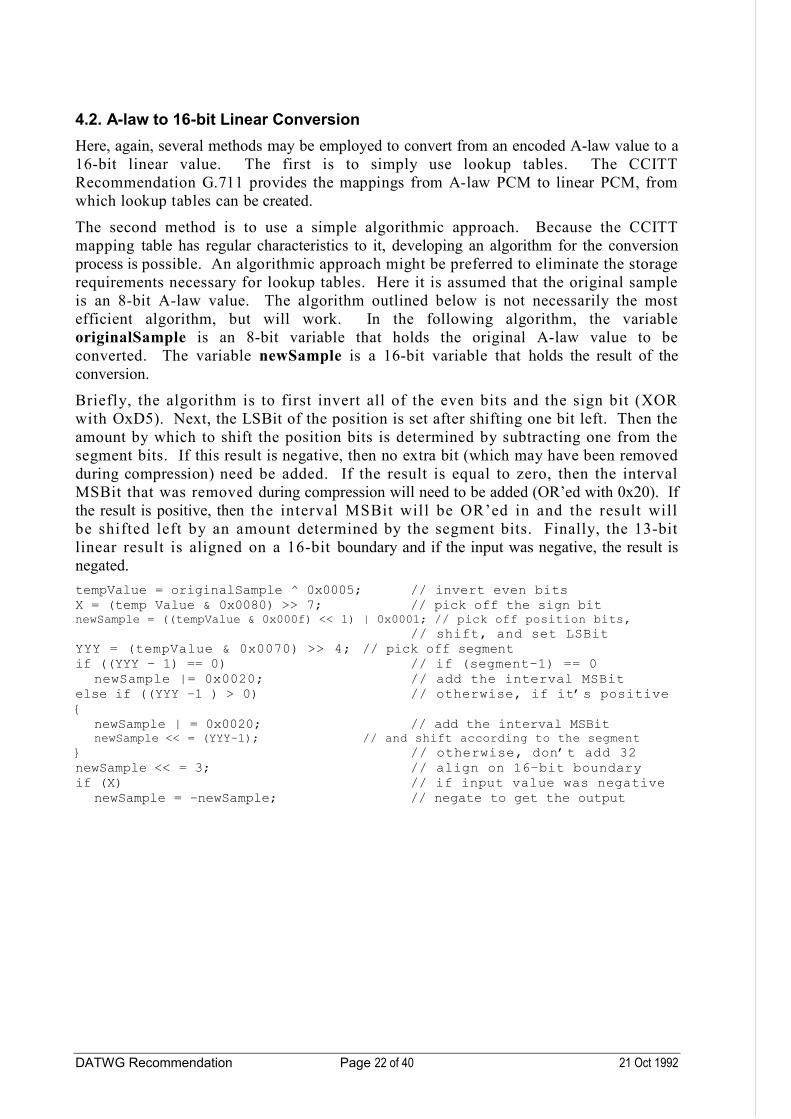
4.2. A-law to 16-bit Linear Conversion
Here, again, several methods may be employed to convert from an encoded A-law value to a 16-bit linear value. The first is to simply use lookup tables. The CCITT Recommendation G.711 provides the mappings from A-law PCM to linear PCM, from which lookup tables can be created.
The second method is to use a simple algorithmic approach. Because the CCITT mapping table has regular characteristics to it, developing an algorithm for the conversion process is possible. An algorithmic approach might be preferred to eliminate the storage requirements necessary for lookup tables. Here it is assumed that the original sample is an 8-bit A-law value. The algorithm outlined below is not necessarily the most efficient algorithm, but will work. In the following algorithm, the variable originalSample is an 8-bit variable that holds the original A-law value to be converted. The variable newSample is a 16-bit variable that holds the result of the conversion.
Briefly, the algorithm is to first invert all of the even bits and the sign bit (XOR with OxD5). Next, the LSBit of the position is set after shifting one bit left. Then the amount by which to shift the position bits is determined by subtracting one from the segment bits. If this result is negative, then no extra bit (which may have been removed during compression) need be added. If the result is equal to zero, then the interval MSBit that was removed during compression will need to be added (OR’ed with 0x20). If the result is positive, then the interval MSBit will be OR’ed in and the result will be shifted left by an amount determined by the segment bits. Finally, the 13-bit linear result is aligned on a 16-bit boundary and if the input was negative, the result is negated.
tempValue = originalSample ^ 0x0005; // invert even bitsX = (temp Value & 0x0080) >> 7; // pick off the sign bitnewSample = ((tempValue & 0x000f) << 1) | 0x0001; // pick off position bits,
// shift, and set LSBitYYY = (tempValue & 0x0070) >> 4; // pick off segmentif ((YYY – 1) == 0) // if (segment–1) == 0
newSample |= 0x0020; // add the interval MSBitelse if ((YYY –1 ) > 0) // otherwise, if it’s positive{
newSample | = 0x0020; // add the interval MSBitnewSample << = (YYY–1); // and shift according to the segment
} // otherwise, don’t add 32newSample << = 3; // align on 16–bit boundaryif (X) // if input value was negative
newSample = –newSample; // negate to get the output

DATWG Recommendation Page 23 of 40 21 Oct 1992
Example:
originalSample => 0x003CnewSample = 0x003C ^ 0x00D5 == 0x00E9X = (0x00E9 & 0x0080) >> 7 = 0x0080 >> 7 == 0x0001newSample = ((0x00E9 & 0x000F) << 1) | 0x0001 =
(0x0009 << 1) | 0x0001 = 0x0012 | 0x0001 == 0x0013YYY = (0x00E9 & 0x0070) >> 4 = 0x0060 >> 4 == 0x0006if ((0x0002 – 1) == 0) == FALSEelse if ((0x0002 – 1) > 0) == TRUE
newSample | = 0x0020 == 0x0033newSample << = (0x0006 – 1) == 0x0660newSample << = 3 = (0x0660 << 3) == 0x3300if (0x0001) == TRUE
newSample = –0x3300 == 0xCD00
Example:
originalSample => 0x00BDnewSample = 0x00BD ^ 0x00D5 == 0x0068X = (0x0068 & 0x0080) >> 7 = 0x0000 >> 7 == 0x0000newSample = ((0x0068 & 0x000F) << 1) | 0x0001 =
(0x0008 << 1) | 0x0001 = 0x0010 | 0x0001 == 0x0011YYY = (0x0068 & 0x0070) >> 4 = 0x0060 >> 4 == 0x0006if ((0x0006 – 1) == 0) == FALSEif ((0x0006 – 1) > 0) == TRUE
newSample | = 0x0020 == 0x0031newSample << = (0x0006 – 1) == 0x0620newSample << = (0x0620 << 3) == 0x3200if (0x0000) == FALSE
Example:
originalSample => 0x00DFnewSample = 0x00DF ^ 0x00D5 == 0x000AX = (0x000A & 0x0080) >> 7 = 0x0000 >> 7 == 0x0000newSample = ((0x000A & 0x000F) << 1) | 0x0001 =
(0x000A << 1) | 0x0001 = 0x0014 | 0x0001 == 0x0015YYY = (0x000A & 0x0070) >> 4 = 0x0000 >> 4 == 0x0000if ((0x000 –1) == 0) == FALSEelse if ((0x000 – 1) > 0) == FALSEnewSample <<= 3 = (0x0x0015 << 3) == 0x00A8if (0x0000) == FALSE

DATWG Recommendation Page 24 of 40 21 Oct 1992
5. Sample Rate Conversion (SRC) Overview
This section contains a brief description of sample rate conversion.
In order to provide complete cross-platform compatibility, the data interchange format must be extended to include sample rate conversion methods. This is necessary because digital audio hardware vendors support sample rates including 8 kHz, 11.025 kHz, 22.05 kHz, and 44.1 kHz. Suppose a software developer records deliverable media at 44.1 kHz, but the user has hardware that only allows playback at 8 kHz. Even if the data format (say 16-bit linear) was agreed upon, the user would not be able to effectively play the media.
With sample rate conversion, media recorded at any sample rate could conceivably be played back at any other rate. However, special care must be taken when performing the sample rate conversion. The techniques utilized in this sample rate conversion can have a dramatic impact on the quality of the converted audio.
The sample rate conversion algorithms described below make use of finite duration impulse response filters. See reference [6] (Digital Processing of Speech Signals, section 2.3.1) for an introduction to FIR filter design as well as additional references.
In the algorithms that follow, several C macros are used which require brief explanation for a thorough understanding of the sample code. These macros are intended to reduce the number of lines of code presented, as well as allow for different implementations of the stated macros.
PUT_SAMPLE(channel, sampleNumber, numberOfChannels, bufferPtr, sample)
Places the value sample into the buffer pointed to by bufferPtr, given the channel (i.e. left or right), the sampleNumber, and the numberOfChannels in the audio stream.
GET_SAMPLE(channel, sampleNumber, numberOfChannels, bufferPtr, sample)
Retrieves the value sample from the buffer pointed to by bufferPtr, given the channel (left or right), the sampleNumber, and the numberOfChannels in the audio stream.
MAC(result, op1, op2)
Performs a multiply/accumulate by first multiplying op1 and op2 and then adding this to result.
M0DULO(index, increment, arrayLength)
Performs a pseudo-modulous operation on index by first adding increment to index and then setting index equal to index mod arrayLength.
RM0DULO(index, decrement, arrayLength)
Performs a “reverse” pseudo-modulous operation on index by first subtracting decrement from index. If the resulting index is negative, arrayLength is added to index.

DATWG Recommendation Page 25 of 40 21 Oct 1992
5.1. Integral Higher-to-Lower Sample Rate Conversion (Decimation)
Decimation is the process of converting from a higher sample rate to a lower sample rate. Simply throwing out samples is sometimes sufficient, but this is usually not the case. Because the higher-sample rate also incorporates a higher cutoff frequency, the decimated version could very well have out-of-band frequencies when played back at a lower sample rate (aliasing). Therefore, a low-pass filter is needed during decimation. One suggested method is to incorporate the low-pass filter, using an FIR, into the decimation process. FIR filters have the advantage of linear phase, unconditional stability, and simple and easy coefficient design. Also, if implemented on a DSP, many of the advantages inherent in DSPs, such as single-instruction cycle multiply/accumulate, simultaneous coefficient and data fetches, and circular buffers, can be used to reduce the time needed to do sample rate conversion.
The basis for this type of filter is to set up a delay line of length N samples. If M represents the decimation factor (for example, if the conversion was from 48 kHz down to 24 kHz, M = 2), then the FIR would calculate a new output for every M inputs into the delay line. The output is the sum of products of N samples and N coefficients (i.e. N taps).
The following algorithm is for a mono digital audio stream only. Expanding this algorithm to include stereo audio streams is straightforward. All variables are 16-bit, except for tmpVal, which is a 32-bit variable, and all samples are assumed to be 16-bit PCM values.
for (j=0; j<numSamples; ){
for (k = 0; k < decimationFactor; k ++){
// put sample into delay lineGET_SAMPLE(CHANNEL_1, j, MONO, originalSamplePtr, temp);PUT_SAMPLE(CHANNEL_1, sampleCounter, MONO, delayLinePtr, temp);
// modify the sample counterMODULO(sampleCounter, 1, numberOfTaps);j++;
}
tmpVal = 0;m = sampleCounter;n = sampleCounter–1;if (n < 0)
n = number0fTaps–1;for (k = 0; k < (numberOfTaps/2); k ++){
GET_SAMPLE(CHANNEL_1, m, MONO, delayLinePtr, temp);GET_SAMPLE(CHANNEL_1, n, MONO, delayLinePtr, temp1);MAC(tmpVal, coeff[k], (temp + temp1));MODULO(m, 1 ,numberOfTaps);RMODULO(n, 1, numberOfTaps);
}PUT SAMPLE(CHANNEL 1, ((j/decimationFactor)–1), MONO, newSamplePtr,
(tmpVal >> 15));}

DATWG Recommendation Page 26 of 40 21 Oct 1992
5.2. Integral Lower to Higher Sample Rate Conversion (Interpolation)
The opposite of decimation is interpolation – effectively adding new samples into the digital data stream at regularly spaced intervals. Once the new values have been inserted, the signal must be low-pass filtered in order to prevent images in the spectrum of the lower sample rate from appearing in the extended baseband of the higher sample rate spectrum. Again, an FIR is the filter of choice for the same reasons as mentioned in Section 5.1 above.
The basis for this type of filter is to insert (L–1) zero-valued samples after each input sample and then low-pass filter the resulting data stream, where L is the interpolation factor (for example, if the conversion was from 22.05 kHz up to 44.1 kHz, L =2). In actuality, the rate expander (the process of inserting zero-valued samples) can be eliminated and the delay line can be shortened from N to (N/L). In this way, the delay line is updated only after L outputs are calculated. The (N/L) data samples are accessed for each set of L output calculations, and each output calculation accesses every Lth coefficient. Doing this effectively skips the coefficients corresponding to zero-valued samples, the multiplication of which would have been zero. Note that (N/L) must be an integer.
sampleCounter = 0;newSampleCount = 0;coeffCounter = 0;for (n = 0; n < numSamples; n++){
for (j = 0; j < (interpolationFactor–1); j++){
tmpVal = 0;k = sampleCounter;h = coeffCounter;for (m = 0; m < delayLineLength; m++){
GET_SAMPLE(CHANNEL_1, k, MONO, delayLinePtr,temp);MAC(tmpVal, coeff[h], temp);MODULO(k, 1, delayLineLength);MODULO(h, interpolationFactor, numberOfTaps);
}PUT_SAMPLE(CHANNEL_1, newSampleCount, MONO, newSamplePtr, (tmpVal >> 15));coeffCounter++;newSampleCount++;
}GET_SAMPLE(CHANNEL_1, n, MONO, originalSamplePtr, temp);PUT_SAMPLE(CHANNEL_1, sampleCounter, MONO, delayLinePtr, temp);MODULO(sampleCounter, 1, delayLineLength);tmpVal = 0;k = sampleCounter;h = coeffCounter;
for (m = 0; m < delayLineLength; m ++){
GETSAMPLE(CHANNEL_1, k, MONO, delayLinePtr, temp);MAC(tmpVal, coeff[h], temp);MODULO(k, 1, delayLineLength);MODULO(h, interpolationFactor, numberOfTaps);
}PUT_SAMPLE(CHANNEL_1, newSampleCount, MONO, newSamplePtr, (tmpVal >> 15));coeffCounter –= (interpolationFactor – 1);newSampleCount++;
}

DATWG Recommendation Page 27 of 40 21 Oct 1992
5.3. Non-integral Sample Rate Conversion (Interpolation and Decimation Together)
Note that if the conversion rate is an integral number, either decimation or interpolation alone will work (for example, converting from 22.05 kHz to 44.1 kHz would only require an interpolator, while converting from 44.1 kHz to 22.05 kHz would only require a decimator). However, if the conversion is a non-integral number, then both an interpolator and a decimator would need to be used. For example, if the conversion was from 8 kHz to 11.025 kHz, then an interpolation with L = 441 followed by a decimation of M = 320 could be used. Therefore, a non-integral sample rate conversion requires additional computation because of the combination. Some of the redundancy involved in combining these two techniques can be eliminated in order to speed the conversion process. For example, the low-pass filtering could be performed only once, instead of once for the interpolation and once for the decimation.

DATWG Recommendation Page 28 of 40 21 Oct 1992
6. ADPCM Reference Algorithms
The DATWG Reference Algorithms for ADPCM compression and decompression are an implementation of adaptive quantization with fixed prediction, discussed in reference [6] (Digital Processing of Speech Signals, section 5.7.1). The specific implementation of the quantizer adaptation using table-based lookup was offered by Intel/DVI® as an open standard for use by the IMA.
This algorithm encodes only the difference between consecutive samples, allowing a wide dynamic range to be maintained with a minimum data bandwidth. It is applicable to all four of the DATWG approved sample rates.
6.1. 16-bit Linear to 4-bit ADPCM Compression
The following algorithm assumes originalSample is a 16-bit two’s complement variable. The variable newSample is the resulting 4-bit ADPCM sample.
The algorithm finds the difference between the originalSample and predictedSample, the output of its predictor. This difference is then quantized down to a 4-bit newSample, using stepsize. The 4-bit newSample has a sign-magnitude format. After newSample has been calculated, it is uncompressed using the same quantization stepsize to obtain a linear difference identical to that calculated by the decompressor. In order to correct for truncation errors in the quantization, ½ is effectively added to newSample during the expansion. This difference is added to predictedSample to form a prediction for the next sequential originalSample. newSample is used to adjust an index into the stepsizeTable. This index points to a new stepsize in the stepsizeTable. predictedSample, stepsize, and index must be static variables between samples.
Preinitialized variables:
predictedSample = 0; /* output of ADPCM predictor */index = 0; /* index into stepsizeTable */stepsize = 7; /* quantizer stepsizeindexTable[16] = {–1, –1, –1, –1, 2, 4, 6, 8, /* Table of index changes */
–1, –1, –1, –1, 2, 4, 6, 8);stepsizeTable[89] = (7, 8, 9, 10, 11, 12, 13, 14, /* quantizer lookup table */
16, 17, 19, 21, 23, 25, 28, 31, 34, 37, 41, 45, 50, 55, 60, 66, 73, 80, 88, 97, 107, 118, 130, 143, 157, 173, 190, 209, 230, 253, 279, 307, 337, 371, 408, 449, 494, 544, 598, 658, 724, 796, 876, 963, 1060, 1166, 1282, 1411, 1552, 1707, 1878, 2066, 2272, 2499, 2749, 3024, 3327, 3660, 4026, 4428, 4871, 5358, 5894, 6484, 7132, 7845, 8630, 9493, 10442, 11487, 12635, 13899, 15289, 16818, 18500, 20350, 22385, 24623, 27086, 29794, 32767);

DATWG Recommendation Page 29 of 40 21 Oct 1992
Calculation for each sample:
/* find difference from predicted sample: */difference = originalSample – predictedSample;if (difference > = 0) /* set sign bit and find absolute value of difference */{
newSample = 0; /* set sign bit(newSample[3]) to 0 */}else{
newSample = 8; /*set sign bit(newSample[3]) to one */difference = –difference; /* absolute value of negative difference */
}mask = 4; /* used to set bits in newSample*/tempStepsize = stepsize; /* store quantizer stepsize for later use */for (i = 0; i < 3; i++) /* quantize difference down to four bits */{
if (difference >= tempStepsize){ /* newSample[2:0] = 4 * (difference/stepsize) */newSample | = mask; /* perform division ... */difference –= tempStepsize; /* ... through repeated subtraction */}tempStepsize >>=1; /* adjust comparator for next iteration */mask >>=1; /* adjust bit-set mask for next iteration */
}/* 4-bit newSample can be stored at this point *//* compute new sample estimate predictedSample */difference = 0; // calculate difference = (newSample + ½) * stepsize/4if (newSample & 4) // perform multiplication through repetitive addition
difference + = stepsize;if (newSample & 2)
difference + = stepsize >> 1;if (newSample & 1)
difference + = stepsize >> 2;difference + = stepsize >> 3;/* (newSample + ½) * stepsize/4 = newSample * stepsize/4 + stepsize/8 */if (newSample & 8) /* account for sign bit */
difference = –difference;/* adjust predicted sample based on calculated difference: */predictedSample + = difference;if (predictedSample > 32767) /* check for overflow */
predictedSample = 32767;else if (predictedSample < –32768)
predictedSample = –32768;
/* compute new stepsize *//* adjust index into stepsize lookup table using newSample */index + = indexTable[newSample];if (index < 0) /* check for index underflow */
index = 0;else if (index > 88) /* check for index overflow */
index = 88;stepsize = stepsizeTable[index]; /* find new quantizer stepsize */

DATWG Recommendation Page 30 of 40 21 Oct 1992
Example:originalSample => 0x873F, predictedSample => 0x8700, stepsize => 73, index => 24difference = 0x873F – 0x8700 == 0x3F == 63if (63 > = 0) == TRUE
newSample = 0;mask = 4;tempStepsize = 73for (i = 0){
if (63 > = 73) == FALSEtempStepsize >> = 1 = (73 >> 1) == 36mask >> = 1 = (4 >> 1) == 2
}for (i = 1){
if (63 > = 36){
newSample |= 2 = (0 | 2) == 2difference –= 36 = (63 – 36) == 27
}tempStepsize >> = 1 = (36 >> 1) == 18mask >> =1 = (2 >> 1) == 1
}for (i = 2){
if (27 > = 18){
newSample | = 1 = (2 | 1) == 3difference – = 18 = (27 – 18) == 9
}tempStepsize >> =1 = (18 >> 1) == 9mask >>= 1 = (1 >> 1) == 0
/* 4-bit newSample can be stored at this point */
difference = 0;if (3 & 4) == FALSEif (3 & 2) == TRUE
difference + = 73 >> 1 = (0 + 36) == 36if (3 & 1) == TRUE
difference + = 73 >> 2 = (36 + 18) == 54difference + = 73 >> 3 = (54 + 9) == 63if (3 & 8) == FALSEpredictedSample + = 63 = (0x8700 + 0x3F) == 0x873F == –30913if ( –30913 > 32767) == FALSEelse if (–30913 < –32768) == FALSE
index + = indexTable[3] = (24 + –1) == 23if (23 < 0) == FALSEelse if (23 > 88) == FALSE

DATWG Recommendation Page 31 of 40 21 Oct 1992
6.2. 4-bit ADPCM to 16-bit Linear Decompression
The following algorithm assumes originalSample is a 4-bit ADPCM sample. The variable newSample is the resulting 16-bit two’s complement variable.
originalSample is uncompressed using a quantization stepsize to obtain a linear difference. In order to correct for truncation errors in the quantization, ½ is effectively added to originalSample during the expansion. This difference is added to predictedSample to form a linear newSample. originalSample is used to adjust an index into the stepsizeTable. This index points to a new stepsize in the stepsizeTable. newSample, stepsize, and index must be static variables between samples.
Preinitialized variables:
predictedSample = 0; /* output of ADPCM predictor */index = 0; /* index into stepsizeTable */stepsize = 7; /* quantizer stepsize */indexTable[16] = {–1,–1,–1,–1, 2, 4, 6, 8, /* Table of index changes */
–1,–1,–1,–1, 2, 4, 6, 8);stepsizeTable[89] = {7, 8, 9, 10, 11, 12, 13, /* quantizer lookup table */
14, 16, 17, 19, 21, 23, 25, 28,31, 34, 37, 41, 45, 50, 55, 60, 66, 73, 80, 88, 97, 107, 118, 130, 143, 157, 173, 190, 209, 230, 253, 279, 307, 337, 371, 408, 449, 494, 544, 598, 658, 724, 796, 876, 963, 1060, 1166, 1282, 1411, 1552, 1707, 1878, 2066, 2272, 2499, 2749, 3024, 3327, 3660, 4026, 4428, 4871, 5358, 5894, 6484, 7132, 7845, 8630, 9493, 10442, 11487, 12635, 13899, 15289, 16818, 18500, 20350, 22385, 24623, 27086, 29794, 32767);

DATWG Recommendation Page 32 of 40 21 Oct 1992
Calculation for each sample:
/* compute predicted sample estimate newSample *//* calculate difference = (originalSample + ½) * stepsize/4: */difference = 0;if (originalSample & 4) /* perform multiplication through repetitive addition */
difference + = stepsize;if (originalSample & 2)
difference + = stepsize >> 1;if (originalSample & 1)
difference + = stepsize >> 2;/* (originalSample + ½) * stepsize/4 =originalSample * stepsize/4 + stepsize/8: */difference + = stepsize >> 3;if (originalSample & 8) /* account for sign bit */
difference = –difference;/* adjust predicted sample based on calculated difference: */newSample + = difference;if (newSample > 32767) /* check for overflow */
newSample = 32767;else if (newSample < –32768)
newSample = –32768;
/* 16-bit newSample can be stored at this point */
/* compute new stepsize *//*adjust index into stepsize lookup table using originalSample: */index + = indexTable[originalSample];if (index < 0) /* check for index underflow */
index = 0;else if (index > 88) /* check for index overflow */
index = 88;stepsize = stepsizeTable[index]; /* find new quantizer stepsize */
Example:OriginalSample => 0x3, newSample[previous] => 0x8700, stepsize => 73, index => 24
difference = 0;if (0x3 & 4) == FALSEif (0x3 & 2) == TRUE
difference + = 73 >> 1 = (0 + 36) == 36if (0x3 & 1) == TRUE
difference + = 73 >> 2 = (36 + 18) == 54difference + = 0x73 >> 3 = (54 + 9) == 63if (0x3 & 8) == FALSEnewSample + = 0x63 = (0x8700 + 63) == 0x873Fif (0x8763 > 32767) == FALSEelse if (0x8763 < –32768) == FALSE
index + = indexTable[0x3] = (24 + –1) == 23if (23 < 0) == FALSEelse if (23 > 88) == FALSEstepsize = stepsizeTable[23] == 66

DATWG Recommendation Page 33 of 40 21 Oct 1992
Algorithm References
[1] Digital Signal Processing Applications Using the ADSP-2100 Family,by The Applications Staff of Analog Devices, DSP Division, ed. Amy Mar,Prentice Hall, Englewood Cliffs, NJ, 1990.
[2] The Art of Digital Audio, Watkinson, J.,Focal Press, Boston, MA, revised reprint, 1989.
[3] Principles of Digital Audio, Pohlmann, K.,Howard W. Sams & Company, Indianapolis, IN, second edition, 1989.
[4] “Object Oriented Approaches to Digital Audio Programming”, Snowman, G.,A Submission to the IMA Digital Audio TWG, Randall House Associates, Inc., July 31, 1991.
[5] “Pulse Code Modulation (PCM) of Voice Frequencies”,CCITT Recommendation G.711, 1972.
[6] Digital Processing of Speech Signals, L. R. Rainer and R. W. Schafer,Prentice Hall, Englewood Cliffs, NJ, 1978.
Reference Algorithm Code Listings
Reference Algorithm Code listings are available on request.
DATWG Recommendation Page 34 of 40 21 Oct 1992
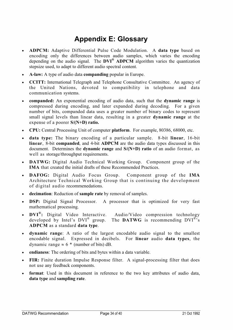
Appendix E: Glossary
ADPCM: Adaptive Differential Pulse Code Modulation. A data type based on encoding only the differences between audio samples, which varies the encoding depending on the audio signal. The DVI® ADPCM algorithm varies the quantization stepsize used, to adapt to different audio spectral content.
A-law: A type of audio data companding popular in Europe.
CCITT: International Telegraph and Telephone Consultative Committee. An agency of the United Nations, devoted to compatibility in telephone and data communication systems.
companded: An exponential encoding of audio data, such that the dynamic range is compressed during encoding, and later expanded during decoding. For a given number of bits, companded data uses a greater number of binary codes to represent small signal levels than linear data, resulting in a greater dynamic range at the expense of a poorer S/(N+D) ratio.
CPU: Central Processing Unit of computer platform. For example, 80386, 68000, etc.
data type: The binary encoding of a particular sample. 8-bit linear, 16-bit linear, 8-bit companded, and 4-bit ADPCM are the audio data types discussed in thisdocument. Determines the dynamic range and S/(N+D) ratio of an audio format, as well as storage/throughput requirements.
DATWG: Digital Audio Technical Working Group. Component group of the IMA that created the initial drafts of these Recommended Practices.
DAFOG: Digital Audio Focus Group. Component group of the IMAArchitecture Technical Working Group that is continuing the development of digital audio recommenedations.
decimation: Reduction of sample rate by removal of samples.
DSP: Digital Signal Processor. A processor that is optimized for very fast mathematical processing.
DVI®: Digital Video Interactive. Audio/Video compression technology developed by Intel’s DVI® group. The DATWG is recommending DVI®’s ADPCM as a standard data type.
dynamic range: A ratio of the largest encodable audio signal to the smallest encodable signal. Expressed in decibels. For linear audio data types, the dynamic range 6 * (number of bits) dB.
endianess: The ordering of bits and bytes within a data variable.
FIR: Finite duration Impulse Response filter. A signal-processing filter that does not use any feedback components.
format: Used in this document in reference to the two key attributes of audio data, data type and sampling rate.

DATWG Recommendation Page 35 of 40 21 Oct 1992
frequency response: A system’s ability to encode the spectral content of audio data between 0 Hz and 20 kHz. A format’s sample rate determines the maximum possible audio frequency encoded (known as the Nyquist frequency) by the following formula: sample rate > 2 * Nyquist frequency.
IMA: Interactive Multimedia Association. Computer/Audio/Video industry tradeassociation that has been working to promote multimedia application development.
interpolation: Increase in sample rate by introduction of processed samples.
linear: A variety of data type with an even distribution of binary codes over the full range of signal level.
low-pass filter: A signal processing function that removes spectral content above a cutoff frequency.
MPC: Multimedia PC. A multimedia hardware and API standard developed by Microsoft and several PC vendors.
PCM: Pulse Code Modulation. A data type based on encoding a signal’s level at a discrete time.
platform: Type of computer system as defined by its hardware architecture and operating system/environment.
real-time: Processing that occurs at the same time as the playback or capture of digital audio/video.
sampling rate: The frequency at which analog audio signals are measured. Each sample is a measurement of an analog signal’s level at a discrete time. This attribute affects an audio format’s frequency response as well as storage/throughput requirements.
S/(N + D) Ratio: Signal to (Noise + Distortion Ratio). Ratio of the original signal level to the level of added noise and distortion. Measured in decibels.
SQAM: Sound Quality Assessment Material. A digital audio compact disc published by the European Broadcasting Union for subjective test purposes.
stream: A time-ordered sequence of samples.
µ-law: A type of audio data companding popular in the U.S. and Japan.

DATWG Recommendation Page 36 of 40 21 Oct 1992
Appendix F: Development of the First Edition of theDigital Audio Recommended Practices
This first edition of the Recommended Practices for digital audio interchange is the work of two groups. Development of the recommendations was begun by the Digital Audio Technical Working Group in July, 1991. The efforts of the DATWG culminated in draft recommendations which were published in a special edition of the IMA Compatibility Project Proceedings in May, 1992. The DATWG then disbanded. A Digital Audio Focus Group (DAFOG) of the IMA Architecture Technical Working Group was created in June, 1992, to continue the work of the DATWG.
The DAFOG welcomes written comments on these recommendations. Comments sent to IMA headquarters will be forwarded to the working group, or may be mailed directly to the chair of the group:
Richard GoldhorAudioFile, Inc.20 Militia Drive, Suite 20Lexington, MA 02173Internet Address: [email protected]
Participants in the Digital Audio Focus and Working Groups
Robert Adams (DATWG) Analog Devices
Thomas Agler (DATWG) TRW LSI Products
Robert Bauman (DATWG) Antex Electronics
Gerard Benbassat (DATWG) Texas Instruments, Inc.
Rita Brennan (DAFOG) Apple Computer, Inc.
Gary Brinck (DAFOG) IBM
Bill Bucklen (DATWG) TRW LSI Products
Kanwar Chadha (DAFOG) Consultant
Willard Chang (DATWG) National Semiconductor
Glen Chapman (DATWG) Online Computer Systems
Michael Chen (DATWG) Fluent Machines, Inc.
Britt Conner (DATWG) Digidex
Geoff Dahl (DATWG) Microsoft Corporation
Mark Davis (DATWG) Dolby Labs
Richard Davis (DATWG) Regency Systems
Richard Goldhor (Chair, DAFOG) AudioFile, Inc.
Carl Goodwin (DATWG) Tektronix, Inc.
Jay Hickam (DATWG) Artisoft

DATWG Recommendation Page 37 of 40 21 Oct 1992
Richard Hodges (DAFOG) Motorola Semiconductor Products, Inc.
Mark Konower (DAFOG) AT&T
Scott Lewis (DAFOG) DSL Enterprises
Jim Mann (DATWG) Compaq Computer Corporation
Brian Marquardt (DAFOG) IMA Compatibility Project
Pat Maupin (DATWG) Video Associates Labs.
Steve McDaniel (DATWG) WordPerfect Corp.
Patrick McElhatton (DAFOG, DATWG) Hewlett-Packard Company
David McFarling (DATWG) Midwest Multimedia
Monty McGraw (Chair, DATWG) Compaq Computer Corporation
David A. Miller (DATWG) Compaq Computer Corporation
Marc Miller (DATWG) Director of Multimedia
Ken Mills (DATWG) System Software Engineer
Jack Murphy (DATWG) Siemens Nixdorf
Davis Pan (DAFOG, DATWG) Digital Equipment Corp.
Jay Reimer (DAFOG) Texas Instruments, Inc.
Tom Rettig (DATWG) Broderbund Software
Reed Rinn (DATWG) Video Associates Labs.
David A. Rivkin (DATWG) Winfon Engineering
Isaac Salzman (DAFOG) Sun Microsystems, Inc.
Uwe Schneider (DAFOG) Fraunhofer
Jeff Scott (DATWG) Crystal Semiconductor
Zeev Shpiro (DATWG) Digispeech, Inc.
Geoff Snowman (DATWG) Multimedia Analyst
John Stautner (DATWG) Aware, Inc.
Mark Stout (DATWG) Compaq Computer Corporation
Tac Sugiyama (DATWG) Sony Corporation of America
Dustin C. Sykes (DATWG) O.A. Com
Steve Turner (DATWG) Antex Electronics
Tom White (DAFOG) Roland Corporation
Dave Wilson (DAFOG, DATWG) Apple Computer, Inc.
Yuhang Wu (DATWG) Digispeech, Inc.
DATWG Recommendation Page 38 of 40 21 Oct 1992
Other Names of Interest
Phil DoddsIMA Compatibility Project DirectorRANDALL HOUSE ASSOCIATES, INC.9 Randall CourtAnnapolis, MD 21401TEL: 410-626-1380FAX: 410-263-0590EMAIL: 70734.1123@CompuServe .com
Original scanned document OCR’d by Daniel F F Ford, Gerroa, Australia(Original formatting not preserved, and corrections applied)
If any errors found please e-mail [email protected] so document can be updated.DF-OCR Issue 1, 7 February 2010

DATWG Recommendation Page 39 of 40 21 Oct 1992
Notes

DATWG Recommendation Page 40 of 40 21 Oct 1992