recommended technical specifications for procurement of
TRANSCRIPT
NISTIR 88-3811
RECOMMENDED TECHNICAL SPECIFICATIONSFOR PROCUREMENT OF EQUIPMENTFOR A TURNING WORKSTATION
June 22, 1988 By:
Issued Kang LeeJune, 1989
NEW NIST PUBLICATIONJune 12, 198?
U.S. DEPARTMENT OF COMMERCE National Institute of Standards & Technology


RECOMMENDED TECHNICAL SPECIFICATIONS
FOR PROCUREMENT OF EQUIPMENT FOR A TURNING WORKSTATION
Kang Lee
Sensor Integration
Automated Production Technology Division
National Institute of Standards
and Technology
Gaithersburg, Maryland
This publication was prepared by United States Government employees as part of their
official duties and is, therefore, a work of the United States Government and not subject
to copyright.


TABLE OF CONTENTS
Page
I. INTRODUCTION 1
II. MAJOR COMPONENTS 2
II. 1. CNC Turning Machine 2
II. 1.1 Functional Requirements 2
II. 1.2 Performance Characteristics 3
II. 1.3 Applicable Specifications, Codes, and Standards 16
II. 1.4 Performance Acceptance Testing 19
II. 1.5 Evaluation Criteria 21
II.2. Robot System 25
11.2.1 System Elements 25
11.2.2 Performance Characteristics 25
11.2.3 Applicable Specifications, Codes, and Standards 30
11.2.4 General Features 30
11.2.5 Safety 34
11.2.6 Final Inspection 35
11.2.7 Documentation and Support 35
11.2.8 Performance Testing 37
11.2.9 Evaluation Criteria 38
III. SUMMARY 40
l

TABLES
Page
TABLE I. Specific Machine Tool Requirements 8
TABLE II. Specific Requirements for Machine Control
Unit, CNC Control 10
TABLE III. Tool Setting and Part Gaging 16
TABLE IV. Machine Accuracies 23
TABLE V. Performance Test 25
ii

FIGURES
Page
Figure 1. The Tool Coordinate System 41
Figure 2. Space Accessible by Robot 42
in


Procurement Specifications
I. INTRODUCTION TO THIS MANUAL
This manual serves as a technical guide to the specifications required to procure
commercially available, major components important in a Turning Workstation. Thespecifications are written specifically for the procurement of an industrial robot and a
turning center (a computerized numerical control (CNC) turning machine) for use in a
technology transfer program. This program is developing a small-batch flexible
manufacturing workstation for the Mare Island Naval Shipyard. Some of the
specifications included herein are developed to meet the technical requirements for the
machining of families of nuclear submarine RISIC parts. This manual is intended to be
used as an aid for those in government, industry and academia who are engaged in
automated manufacturing research.
1

Procurement Specifications
II. MAJOR COMPONENTS
1. CNC TURNING MACHINE
This turning center will be used in an extended series of experiments to evaluate the
effectiveness and limitations of on-line computer correction of machine-tool performance
and completely automated operation in a small batch manufacturing environment. Theturning center will become a research element of a microprocessor-based, network
controlled turning workstation and will be automatically tended by an industrial robot(s)
and controlled by a host computer, a workstation controller. This machine tool will run
untended by a human operator.
1.1. Functional Requirements
The turning center shall be designed and engineered to meet the purchaser’s
requirements as follows:
a) The turning center shall be delivered and installed as a self-contained unit
capable of performing CNC machining operations on parts held in a 3-jaw power
chuck or mounting between centers.
b) The turning center shall be controlled by a microprocessor-based machine
control unit (MCU) interfaced to the machine tool. The MCU shall receive
commands from a program stored in a self-contained memory unit or from a
program manually entered from a keyboard on the machine controller as manual
data input (MDI). The memory shall accept programs from memory storage,
magnetic tape, and MDI inputs. It shall be possible to save programs for future
use by writing the memory to external storage such as a magnetic tape cassette
recorder, paper tape punch, and bubble memory cartridge reader through
appropriate interfaces.
c) The turning center machine-tool-controller software shall be programmed in a
high-level structured language such as ADA or Pascal so that it can be modified by
the purchaser. The contractor shall furnish a listing of the controller source code
and an editor to modify the software.
d) The turning center shall provide a machining capability "C" axis, that is, the
spindle position can be programmed via the CNC controller.
2

Procurement Specifications
e) The turning center shall have a quick change tool head at the tool turret that
can be actuated remotely for quick change of tooling.
f) The turning center shall have turret-mounted live tooling for all secondary
machining operations. Secondary machining operation shall include, but not be
limited to, face milling, slotting, and off-axis drilling and tapping.
g) The turning center shall have an automatic gaging system, furnished with a tool
and a workpiece gaging probe, and necessary software integrated into CNC control.
h) The turning center shall be equipped with automatic lathe door open and door
close functions.
1.2. Performance Characteristics
1.2.1. General Description
The machine tool shall be new and essentially one of the manufacturer’s current models.
The machine tool shall be a 2-axis, continuous path positioning/contouring machine with
a rotary turret for tool positioning. In addition, the machine tool shall be capable of
holding the spindle in position in order to allow the use of live tooling. The design of
the machine shall include features and components necessary for maintaining alignment
and accomplishing turning, boring, threading, drilling, and shaft turning operations as
well as off-axis boring, threading, drilling and milling. The machine shall have a
horizontal axis spindle. Motion in the X and Z axes, spindle operation, and turret
indexing shall be directed by a computer numerical control (CNC) type MCU. Themachine shall have full-axis servo drives on the linear axes with precision positioning
feedback devices and turret indexing with at least 12 indexing positions to allow the
specified machine capacity to be exercised.
The machine functions shall be controllable directly by manually-operated control
devices, semi-automatically by manual data input devices, and automatically from parts
programs in data memory, and remotely from a computer.
All parts of the machine or system that are subject to wear, breakage, or distortion shall
be accessible for adjustment, replacement, and repair.
1.2.2. Detailed Requirements
3

Procurement Specifications
Construction Features: The machine shall be so constructed that when installed, filled
with operating fluids, and connected to power, it will be ready for operation. Themachine shall be constructed of parts which are without defects and free of repair. Thestructure shall be capable of withstanding all forces encountered during operation of the
machine to its maximum rating and capacity without permanent distortion.
Castings and Forgings: All castings and forgings shall be free of defects, scale, and
mismatching. No process such as welding, peening, plugging, or filling with solder or
paste shall be used for reclaiming any defective part.
Welding, Brazing, or Soldering: Welding, brazing or soldering shall be employed only
where specified in the original design. None of these operations shall be employed as a
repair measure for any defective part.
Fastening Devices: All screws, pins, bolts, and similar parts shall be installed in such a
manner as to prevent change of tightness. Those subject to removal or adjustment shall
not be swaged, peened, staked, or otherwise permanently deformed.
Surfaces: All surfaces of castings, forgings, molded parts, stampings, and welded parts
shall be cleaned and free from sand, dirt, fins, sprues, flash, scale, flux, and other
harmful or extraneous materials. All edges shall be either rounded or beveled unless
sharpness is required to perform a necessary function. Except as otherwise specified
herein, the condition and finish of all surfaces shall be in accordance with the
manufacturer’s standard commercial practice. The manufacturer’s standard-color paint
shall be used where applicable.
Threads: All threading of parts shall be done in the SI (metric) unit system, or inch
system conforming to Federal Screw Thread Standard H28, excluding hydraulic
components and manufacturer’s standard electronic connectors.
Plates: All words on speed-and-feed indicating plates and/or instruction plates shall be
in the English language and engraved, etched, embossed, or stamped in boldface
characters on a contrasting background.
Gears: The gears used in the machine shall be machined in either the SI (metric) unit
system or in inches. In either case, the gears shall be suitable for the intended purpose,
and shall be heat-treated by a process that will impart the necessary toughness and
hardness that will enable the gear train to transmit full-rated torque without failure or
premature wear.
4

Procurement Specifications
Lubrication: All bearings (except sealed-for-life type), matting gears, and sliding parts
shall be provided with means for automatic lubrication with a system of capacity for at
least 100 hours. Oil reservoirs shall be fitted with oil-level sight gages. Manually
operated systems for ways and remote areas shall have control handles mounted in
accessible locations. All oil holes, grease fittings, and filter caps shall be easily
accessible.
Interchangeability: To provide for replacement of work parts, all parts bearing the same
part number shall be functionally interchangeable without modification of part or
machine, and shall be dimensionally identical within the manufacturing tolerance limits in
use by their manufacturer.
Reclaimed Materials: The machine shall contain reclaimed materials to the maximumextent possible without jeopardizing its intended use or its performance. The reclaimed
materials shall have been reprocessed, remanufactured or recycled in a manner which
restores them to the same chemical composition and physical properties as the materials
originally selected for use on the machine. Reclaimed materials shall include iron, steel,
copper, brass, aluminum, glass, fiber products, plastics, and elastomers that have been
collected from discarded solid, liquid, semisolid, or gaseous waste such as garbage,
refuse, or sludge.
1.2.2. 1. Component Specification
The principal components of the turning center shall include, but shall not be limited to:
bed base, turret, carriage, 3-jaw chuck, spindle, head stock, numerically controllable axes,
precision feedback devices, coolant system, electrical system, hydraulic system, numerical
control system, machine/control system interfaces, and appropriate safety devices. These
components shall provide a machine tool that conforms as described in Table I Specific
Machine Tool Requirements and Table II Specific Requirements for Machine Control
Unit, CNC Control.
Numerical Control System: The turning center shall have a fully automatic numerical
control system with a machine control unit (MCU), axis servo drives, and position
feedback devices. This control system shall be configured in a manner consistent with
the functional requirements stated in Section 1.3 above to allow the purchaser to
accomplish the operations outlined in Sections 1.1 and II.3. The MCU shall have the
features listed and described in Table II, and shall operate as follows: The system shall
control the machine to accomplish axis movement, spindle operation, turret indexing,
and all other part-program-directed functions. Spindle operations include spindle locking
5

Procurement Specifications
in order to machine with the rotary tooling. The MCU shall be a continuous-path
contouring unit.
System Software: Part programs, the operating program, tool data, materials data, time
cycles, and resident diagnostics shall be stored and processed by the MCU utilizing
semiconductor memory. The MCU memory capacity shall be sufficient to store the
equivalent or at least 1000 feet (394 m) of multiple part-program tape data in addition
to the storage of all other software of the system. Programs stored in memory from
tape input shall be accessible for repetitive execution without the use of the tape reader.
The MCU shall translate the program data into machine control language and shall
store this in the memory.
The MCU shall also be capable of accepting binary code perforated paper tape input
and magnetic tape input.
The system shall control the axis servo drives to move the controlled elements to the
program-commanded positions with the MCU regulating speed, direction, sequence, and
dwell. The system shall position the controlled slides in rapid traverse, feed in any
controlled axis at the program feed rate, elect spindle speed and direction of rotation,
initiate tool index, and control the flow of coolant fluid.
Movement of the X and Z turret axes shall be actuated through closed-loop electric or
hydraulic servo mechanisms. The speed shall be variable on X and Z movements. The
feed drives of the linear axes shall be accomplished using antibacklash ball lead screws
with preloaded recirculating ball nuts. Positioning feedback devices on the axes shall
provide the MCU with position data in order that it may be compared with the control
output and the machine slides moved in the direction that will tend to reduce the
difference to zero.
The contractor shall furnish source code such that the system software can be modified.
Numerically Controlled Axes: With machine axis and motion nomenclature assigned in
accordance with EIA RS-267, the MCU shall control the axes of the machine to
perform turning, boring, drilling, continuous-path contouring, and threading through
simultaneous movements of the X and Z axes utilizing linear interpolation and circular
interpolation. Positioning axes shall execute program movement at fixed or programmed
velocities independent of the movements of any other axis. Contouring axes shall have
simultaneous start and completion of defined moves with vector and velocity control.
6

Procurement Specifications
The MCU shall provide interface circuitry and plug receptacles to output stored
programs from the memory to external storage.
The MCU shall provide interface circuitry and plug receptacles to output stored
programs from the memory to external storage. Memory space formerly occupied by
deleted programs shall be accessible for reutilization. The methods used shall be those
stated in Section II.l.l (b).
MCU’s utilizing volatile-type memory shall have a self-contained emergency power
source that will maintain program and data storage for a period of not less than 24
hours.
Auxiliary Functions: The MCU shall respond to all program command auxiliary
functions. System preparatory and miscellaneous functions shall be coded in accordance
with EIA RA-274, Appendix B. Preparatory functions shall include interpolation, fixed
cycles, and dwell. Miscellaneous functions shall include program stop, optional program
stop, end of program, spindle CW, spindle CCW, spindle off, coolant on, coolant off,
turret index, end of program (rewind) and program restart.
7

Procurement Specifications
TABLE I. Specific Machine Tool Requirements
Characteristics must not be less than the requirements shown, except when a range is
specified; acceptable performance for a range is from the smaller figure, or less, to the
larger figure, or more.
X Axis Travel: 6-inch working travel
Z Axis Travel: 8.5-inch working travel
Resolution, Both Axes: 0.00001 inch
Maximum Turning Diameter, w/3-jaw chuck: 12 inches
Maximum Turning Length, distance between centers: 15 inches
3-Jaw Chuck Size, Powered: 12-inch (include at least one set of soft jaws and one set of
hard jaws)
Collet Chuck Size, Powered: N/A
Hole Through Spindle: 2.5 inches
Spindle Speed Range: 45-3000 rpm
Main (Spindle) Drive Motor: 30 hp
Spindle Indexing: 1800 positions per revolution(0.2 degree )
Minimum Tool Positions: 12
Minimum Turret Indexing Positions: 12
Rapid Traverse Rate (All Axes): 300 ipm
Rotary Tool Spindle Speed: 0-3000 rpm
Rotary Tool Spindle Motor: 7 hp
8
Procurement Specifications
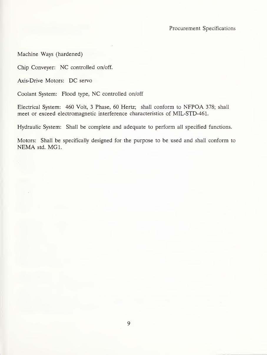
Machine Ways (hardened)
Chip Conveyer: NC controlled on/off.
Axis-Drive Motors: DC servo
Coolant System: Flood type, NC controlled on/off
Electrical System: 460 Volt, 3 Phase, 60 Hertz; shall conform to NFPOA 378; shall
meet or exceed electromagnetic interference characteristics of MIL-STD-461.
Hydraulic System: Shall be complete and adequate to perform all specified functions.
Motors: Shall be specifically designed for the purpose to be used and shall conform to
NEMA std. MG1.
9

Procurement Specifications
TABLE II. Specific Requirements for Machine Control
Unit, CNC Control
Characteristics must not be less than the requirements shown, except when a range is
specified; acceptable performance for a range is from the smaller figure, or less, to the
larger figure, or more.
Controlled Axes: 2 Axes (X and Z), simultaneously
Decimal-Point Programming
Increment System:
Least Input Increment: 0.00001 inch
Maximum Programmable Dimension: 99.9999 inches
Program Input/Output: RS-232 interface, paper-tape reader, MDI
Rapid Traverse Override: 100%, 50%, 25%, 0%, or 0-100% or greater.
Feed rate Override: 0-110%
Automatic Acceleration/Deceleration
Absolute/Incremental Programming
Absolute-Zero-Point Programming
Linear/Circular Interpolation
Tool Offset: 32 pairs in memory
Dry Run Capability
Part Program Storage Capacity (equivalent): 1000 feet of tape program
Backlash Compensation: 0-0.255 mm (0-0.010 inch)
10

Procurement Specifications
Single Block Operation
Interlock
Machine Lock
Stored Stroke Limit
Feed Hold
Tape Reader: The MCU shall have a photoelectric-type tape reader for holding,
feeding, and reading one inch, eight channel perforated tape as required herein. Thetape reader shall be located on the exterior of the MCU, in a position that is readily
accessible, visible, and protected from environmental contaminants. The reading speed
of the tape reader shall be not less than the capability of the MCU to receive and
process such input data and, in any event, not less than 150 characters per second. The
MCU shall have controls for feeding, rewinding, and stopping the tape for single and
multiple block operation to include stored program and sequence number search.
Parity Check: The MCU shall have a parity check system which stops the tape reader
and illuminates an error indicating light on the control panel or produces an error
message on the CRT or readout when the number of holes read in a traverse row of
tape data does not comply with the program character code (EIA RS-244 or EIA RS-
358). The system shall include controls for overriding parity error.
Tape Hold Verification: The reader shall be stopped and a read error signal given if
parity check indicates that the number of holes read does not conform to the established
tape format, if sprocket hold verification detects the absence of a hole, or if there is
tape misalignment. It shall be possible to feed tape data which is not required for
control operation through the reader without registering a parity error, such as leader
information containing program identification data, operator messages, and other
functions as appropriate.
Block Delete: The MCU shall have a block delete system which can be controlled by
the operator for reading through or ignoring blocks of tape data.
Buffer Storage: The MCU shall have buffer storage for transferring blocks of program
data from the tape reader to internal storage without delaying the next incoming block
or interrupting the active command functions. The buffer shall delay or store input data
11

Procurement Specifications
until allocated by the controlling devices. The buffer shall store one or more blocks of
program data.
MCU Console: The MCU console shall be constructed in accordance with the
applicable requirements of ELA RS-281. The MCU shall be a solid-state, modular-type
unit. The console shall have a control panel for displaying the visual signals and
operating controls of the system and machine. The console shall have removable panels
or other means that provide access to all circuit boards, wiring, and other components
contained within. Circuits shall include tagged or color-coded wiring, terminal board
markings, and branch circuit fusing. The MCU shall include electrical and safety
interlocks as required for the protection of the system, machine, and the operator. Theconsole shall be sealed to protect the contained components from dust or other
environmental matter that could adversely affect performance of the MCU. The system
shall function effectively and accurately within any ambient temperature ranging between10° C and 48° C and in a relative humidity of up to 95 percent.
Control Panel: The control panel of the MCU shall include an alphanumeric keyboard
and other switches and push buttons necessary to control the unit. A cathode ray tube
(CRT) display shall be provided.
Program Edit: The MCU shall be configured with an edit mode that is operational
through the control panel keyboard and other controls as necessary for the display and
modification of program data of tape being input and programs stored in memory. The
mode shall include controls for searching the selected data input source (tape or data
memory) both forward and reverse and block-by-block for a designated sequence
number of block of program data. When located, the designated block shall be
displayed for review and editing. The mode shall permit data to be deleted or altered
and shall permit additional blocks to be inserted between blocks of program data. It
shall also permit the edited data of tape programs to be input to data memory and
merged with the programs for tape execution.
Tape Punch Interface: The MCU shall include a tape punch output interface with
necessary hardware and software for allowing the coded data of stored programs to be
produced by a tape punch unit. In order to facilitate punch unit connection, the
interface shall include necessary circuitry and a plug receptacle in accordance with ELARS-232.
Direct Machine Control: The MCU console shall be configured to provide direct
override control over feed rates and spindle speed and to provide jogging capability on
12

Procurement Specifications
all axes. Feed rate override shall allow manual adjustment of the tape or stored
program commanded feed rate for each axis controlled by the numerical control system.
The override shall be as specified in Table II, and have a continuous low- and high-
speed bidirectional jog movements of the slides for each controlled axis.
Program Adjustment: The MCU shall have controls for locating the zero reference (set)
point at any position throughout the range of departure for each controlled axis.
The MCU shall have linear and circular interpolation capability for directing contouring
cuts by simultaneous incremental or absolute movements of any or all axes controlled.
Circular interpolation shall provide a means within the system for generating an arc in
any one quadrant using one block of program data. Direction of the tool center arc
shall be clockwise or counterclockwise.
The MCU shall be configured to allow tool length offsets up to at least 999.999 mm or
99.9999 in, as applicable, and gauge lengths ranging from not more than 0.003 mm(0.0001 in) to at least 999.999 mm or 99.9999 in, as applicable, for at least 12 tools.
Tool length offsets and gauge lengths shall be set through the control panel and shall be
displayed on the control panel.
Direct Numerical Control Interface (DNC): A DNC interface to the MCU shall be
provided that permits DNC operation of the machine tool and bidirectional
communications with a host computer. The protocols utilized to implement
communications and error checking on the computer link shall be described. Thehardware to implement the DNC interface at the MCU, and a 300-foot cable and
connector for the computer link shall conform to RS-232C or EIA-422. The minimumdata transmission rate shall be 9600 baud. The DNC interface and computer link shall
permit the following operations: a) transmit machine control data from the host
computer to the MCU for storage in program memory, b) transmit edited machine
control data from MCU memory to the host computer.
Safety Devices: Covers, guards, or other safety devices shall be provided for all parts of
the machine that present safety hazards. The safety devices shall not interfere with the
operation of the machine. The safety devices shall prevent unintentional contact with
the guarded part, and shall be removable to facilitate inspection, maintenance, and
repair of the parts. All machine parts, components, mechanisms, and assemblies
furnished on the machine, whether or not specifically required herein, shall comply with
all of the Standards promulgated under OSHA that are applicable to the machine itself.
13

Procurement Specifications
Maintenance tools: One set of wrenches and operating and repair tools shall be
furnished according to the normal practice of the manufacturer.
Documentation: At least three copies of documentation for the complete turning center
shall be supplied. This shall include operating, service, and programming manuals as
well as mechanical drawings, and complete electronic and electrical schematics. In
addition, source code for the operating system shall be supplied.
Training: Reasonable technical training in the operation, maintenance, programming,
and routine use of the turning center shall be provided at the buyers site. For this
purpose, the manufacturer’s standard courses in the machine operation, maintenance,
programming, and routine use will suffice.
Plates: A corrosion-resistant metal nameplate shall be securely attached to the machine.
The nameplate shall contain the information listed below. If the machine is a special
model, the model designation shall include the model of the basic standard machine and
a suffix identified in the manufacturer’s permanent records. The captions listed may be
shortened or abbreviated, provided the entry for each such caption is clear as to its
identity:
Nomenclature
Manufacturer’s Name
Manufacturer’s Serial Number
Manufacturer’s Model Designation
Class, Axes Pos., Axes Cont.
Size, HP Spindle MotorPower Input (Volts, Total Amps, Phases, Frequency)
Contract Number/P.O. Number
Date of Manufacture
Also, a lubrication chart or plate shall be permanently and securely attached to the
machine. It shall be placed in a transparent plastic folder or permanently sealed
14

Procurement Specifications
between clear plastic sheets with suitable means for mounting. The following
information shall be furnished on the chart or plate:
Points of Application
Service Interval
Type of Lubricant
Viscosity
Chip and Coolant Shielding: The machine shall be provided with shielding for the
reasonable containment of coolant and chips. The containment device must be
transparent or contain a transparent window to provide work area visibility.
Power Operated Chuck: The chuck shall be a heavy-duty, three-jaw self-centering chuck
not less than the size required in Table I. The chuck shall be operated by pneumatic or
hydraulic power as normally supplied. Chuck grip pressure and manual operating
controls shall be provided.
In-Process Part Gaging: The machine tool shall be equipped with a turret-mounted
touch probe and necessary control software to provide automatic in-process part gaging
operation on the machine. The required repeatability of the probe is given in Table III.
15

Procurement Specifications
TABLE III. Tool Setting and Part Gaging
Tool Setting Station :
Repeatability of the touch probe .000020 inch, one standard deviation
Positioning repeatability of the arm +/- .0002”
In-process Gaging Probe :
Repeatability .000020 inch, one standard deviation
Tool Setting Station: The machine tool shall be equipped with a tool setting station and
necessary control software to provide automatic measurement of tool offsets on the
machine and update the tool offset registers automatically. The required repeatability of
the tool setting station is given in Table III.
Tooling: The machine turrets shall be equipped with tapered shank tooling that can
readily be changed by a robot. Live tooling is not required to have tapered shank.
Automatic Lathe door: The lathe door opening and closing shall be remotely under
CNC control. When the door is fully open, it shall have a minimum of 21-inch wide
clearance for robot access into the lathe work volume.
1.3. Applicable Specifications, Codes, and Standards
The following documents of the issue in effect on date of request for proposals form a
part of this specification to the extend specified herein.
UNITED STATES MILITARY STANDARDS
MIL-STD-1815 ADA Programming Language
16

Procurement Specifications
MIL-STD-461 Electromagnetic Interference Characteristics Requirements for
Equipment
(Copies of military specifications, standards, drawings, and publications
required by contractors in connection with specific procurement should be
obtained from the procuring activity or as directed by the Contracting Officer.)
OCCUPATIONAL SAFETY AND HEALTH ACT (OSHA) OF 1970
Title 29, Code of Federal Regulations, Chapter XVII, Part 1910, and
amendments. Occupational Safety and Health Administration Standards
FED-STD-H28 SCREW THREADS FOR FEDERAL SERVICES
ANSI B1 - ISO Metric Screw Threads
(Application for copies should be addressed to the Superintendent of
Documents, Government Printing Office, Washington, CS 20402.)
AMERICAN NATIONAL STANDARDS INSTITUTE (ANSI)
ANSI X3.9-FORTRAN
ANSI X3.37-Programming Language APT
(Application for copies should be addressed to the American National
Standards Institute, Dept. 969, 1430 Broadway, New York, NY 10018.)
NATIONAL FIRE PROTECTION ASSOCIATION (NFPA) STANDARDS
NFPA No. 79-Electrical Standard for Metalworking Machine Tools.
(Application for copies should be addressed to the National Fire Protection
Association, 470 Atlantic Avenue, Boston, MA 02110.)
ELECTRONIC INDUSTRIES ASSOCIATION (EIA) STANDARDS
RS-227 One-Inch Perforated Paper Tape
17

Procurement Specifications
RS-232 Interface Between Data Terminal Equipment and DataCommunication Equipment Employing Serial Binary Data Interchange
RS-267 Axis and Motion Nomenclature for Numerically Controlled MachineTools
RS-274 Interchangeable Perforated Tape Variable Block Format for
Positioning, Contouring, and Contouring/Positioning Numerically Controlled
Machines
RS-281 Electrical and Construction Standards for Numerical Machine Control
RS-350 Subset of USA Standard Code for Information Interchange for
Numerical Machine Control Perforated Tape
(Application for copies should be addressed to Electronic Industries
Association, Engineering Dept., 200 Eye St., N.W., Washington, DC 20006.)
INSTITUTE OF ELECTRICAL AND ELECTRONICS ENGINEERS (IEEE)
STANDARDS
IEEE-488 Digital Interface for Programmable Instrumentation
IEEE-770-1982 Pascal Computer Programming Language
(Application for copies should be addressed to the Institute of Electrical and
Electronics Engineers, 345 E. 47th St., New York, NY 10017.)
NATIONAL ELECTRICAL MANUFACTURER’S ASSOCIATION (NEMA)STANDARDS
MG1 Motors and Generators
(Application for copies should be addressed to the National Electrical
Manufacturer’s Association, 155 East 44th St., New York, NY 10017.)
NATIONAL MACHINE TOOL BUILDERS’ ASSOCIATION (NMTBA)
18

Procurement Specifications
Definition and Evaluation of Accuracy and Repeatability for Numerically
Controlled Machine Tools
(Application for copies should be addressed to the National Machine Tool
Builders’ Association, 7901 Westpark Drive, McLean, VA 22101.)
(Technical society and technical association specifications and standards are
generally available for reference from libraries. They are also distributed
among technical groups and among Federal agencies.)
1.4. Performance Acceptance Testing
Contractor Responsibility: The contractor shall provide and maintain an effective
inspection system which will assure that all articles submitted to the purchaser for
acceptance conform to contract requirements whether manufactured or processed by the
contractor, or procured from subcontractors or suppliers. Quality assurance personnel
shall perform or verify all inspections or tests. The purchaser reserves the right to
perform any inspections or tests necessary to assure articles conform to prescribed
requirements.
The contractor shall perform sufficient inspections of parts, components, and assemblies
to assure that articles conform to the latest applicable drawings and specifications with
respect to workmanship, configuration, finish, performance, and identification. These
inspections shall include receiving, fabrication, assembly, end-item, and shipping phases.
The contractor shall maintain calibrated suitable inspection equipment of range,
accuracy, and type necessary to ensure conformance; maintain control over processes
which are not readily detectable or measurable by inspection of finished articles; and
maintain effective and positive control of nonconforming articles.
It is intended that documentation will be minimal; however, the contractor shall provide
objective evidence of quality in the form of records of inspections. The contractor’s
existing documentation shall be utilized whenever possible, subject to review by the
purchaser.
The supplier is responsible for the performance of all inspection requirements as
specified herein. Except as otherwise specified in the contract or order, the supplier
may use his own or any other facilities suitable for the performance of the inspection
specified herein, unless disapproved by the purchaser. The purchaser reserves the right
to perform any of the inspections set forth in the specification when such action is
19

Procurement Specifications
deemed necessary to ensure that supplies and services conform to prescribed
requirements.
1.4.1. Preshipment Examination
The purchaser reserves the right to examine the completed machine tool before it is
packaged for shipment to confirm that it meets the specified requirements in Sections
II.l.l and II.1.2 above (including Table I and Table II).
The purchaser reserves the right to examine source code for the controller software to
confirm that it is suitable for the requirement in Sections II.l.l and II. 1.2.
All tapes, materials, and tools required to perform and evaluate these tests shall be
furnished by the supplier. The numerical control test tapes and computer printouts used
shall become the property of the purchaser.
1.4.2. Operational Test
The machine and its numerical control system shall be operated in accordance with the
manufacturer’s standard operating test procedure for warm-up and run-off checks.
During the warm-up period, proper operation of all manual controls, motors, adjustment
mechanisms and accessories shall be verified. After warm-up, the machine shall be
cycled continuously under numerical tape control for a period of not less than 4 hours.
This operation shall include turret indexing, spindle speed, and feed rate changes that
include the highest, intermediate, and lowest settings of each range, rapid traverse of all
slides, simultaneous movement of slides and automatic feed cycles as applicable. The
numerical control system shall be further tested to verify proper operation of MDI,program edit, and system diagnostics. Should a malfunction occur, it shall be corrected
and the operational test repeated until a full 4 hours of running time is completed
without failure.
1.4.3.
Alignment and Accuracy Test
The machine and its numerical control system shall be tested for conformance with the
alignment and accuracy requirements listed in Table IV. The evaluation of accuracy
shall follow NMTBA guidelines unless otherwise specified.
20
Procurement Specifications
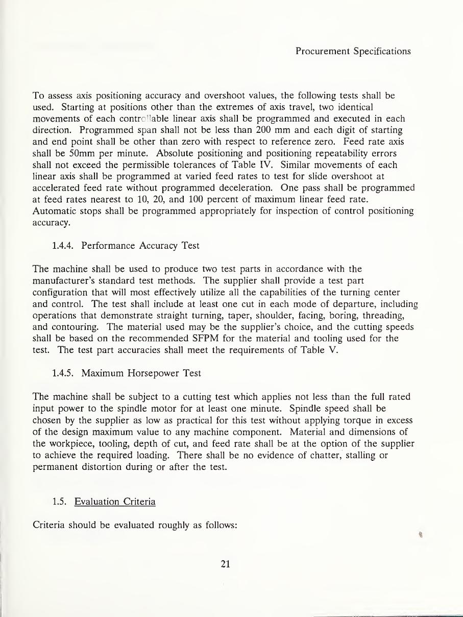
To assess axis positioning accuracy and overshoot values, the following tests shall be
used. Starting at positions other than the extremes of axis travel, two identical
movements of each control able linear axis shall be programmed and executed in each
direction. Programmed span shall not be less than 200 mm and each digit of starting
and end point shall be other than zero with respect to reference zero. Feed rate axis
shall be 50mm per minute. Absolute positioning and positioning repeatability errors
shall not exceed the permissible tolerances of Table IV. Similar movements of each
linear axis shall be programmed at varied feed rates to test for slide overshoot at
accelerated feed rate without programmed deceleration. One pass shall be programmed
at feed rates nearest to 10, 20, and 100 percent of maximum linear feed rate.
Automatic stops shall be programmed appropriately for inspection of control positioning
accuracy.
1.4.4. Performance Accuracy Test
The machine shall be used to produce two test parts in accordance with the
manufacturer’s standard test methods. The supplier shall provide a test part
configuration that will most effectively utilize all the capabilities of the turning center
and control. The test shall include at least one cut in each mode of departure, including
operations that demonstrate straight turning, taper, shoulder, facing, boring, threading,
and contouring. The material used may be the supplier’s choice, and the cutting speeds
shall be based on the recommended SFPM for the material and tooling used for the
test. The test part accuracies shall meet the requirements of Table V.
1.4.5. Maximum Horsepower Test
The machine shall be subject to a cutting test which applies not less than the full rated
input power to the spindle motor for at least one minute. Spindle speed shall be
chosen by the supplier as low as practical for this test without applying torque in excess
of the design maximum value to any machine component. Material and dimensions of
the workpiece, tooling, depth of cut, and feed rate shall be at the option of the supplier
to achieve the required loading. There shall be no evidence of chatter, stalling or
permanent distortion during or after the test.
1.5.
Evaluation Criteria
Criteria should be evaluated roughly as follows:
21

Procurement Specifications
a) Mechanical specifications: 35%b) Control system specifications : 35%c) General requirements (documentation, training, etc.): 15%d) Price and delivery: 15%
Past performance, as it pertains to prior relevant contracts, should be considered in the
evaluation of each criterion.
9
22

Procurement Specifications
TABLE IV. Machine Accuracies .
The machine accuracies shall be within the given tolerances when checked in accordance
with II.1.4.3.
Bedwav Level
Head end: .0005712"
Tail end: .0005712"
Spindle Nose
Center runout: .0005"
Nose runout: .0003"
Face runout: .0005"
Runout of Axis of Spindle Through Hole fT.I.R.l
At nose: .0003"
At end of 12" test bar: .0006"
Parallelism of Spindle Axis With Carriage Path
Vert, plane low at end of 12" test bar: .0005"
Horz. plane low at end of 12" test bar: .0004"
Cross Slide Alignment
Concave on 12" diameter: .001"
Reversal Lost Motion (Uncompensated Rotary Feedback)
Z axis: .001"
X axis: .001"
Motion Repeatability (TJnidirectionaB
Z Axis: .00005"
X Axis: .00005"
Parallelism of Axis of Centers With Carriage Path in 12" Length
Vert, plane up at tail: .0008"
Horz. plane forward at tail: .002"
Repeatability of Index of Turret
End: .0003"
23

Procurement Specifications
Face: .0003"
Parallelism of Turret Boring Bar with Carriage Path in 6"
Each position top of bar: ±.002"
Each position side of bar: ±.002"
Coincidence of Bar Holder Vertical
Centerline with Spindle Centerline
Each position: ±.002"
Parallelism of Tool Locating Surfaces
with Turret Slide Path in 4"
Each tool pocket face: ±.002"
24

Procurement Specifications
TABLE V. Performance Test .
The machine shall perform within the given tolerances when checked in accordance with
II.1.4.4.
Straight turning test, outside diameters:
Turning diameter cylindrical to within 0.00T' in 12"
Turned diameter round to within 0.0003"
Facing cut, flatness, concave only 0.0007" in 10" diameter
Turned diameter to within 0.001" in 12"
Boring cut, 5" depth of bore, cylindrical to within 0.0005" and round to within
0.0005"
Thread lead error 0.001/inch
Comparison of dimensions of two test parts 0.0005" max. deviation
Test part must demonstrate surface finish not rougher than 60 microinches.
2. ROBOT SYSTEM
2.1. System Elements
The principle system elements consist of the mechanical system, which includes the arm,
joints, power source and power transmissions, and the control system, which includes the
means for translation of programmed instructions into position and sequence commands,
and the means for measuring and regulating the configurations of the mechanical system
resulting from those commands. The control system also includes a pendant for teach
programming, a means to save and later access programs which reside external to the
systems, and a means to program robot motions via an off-line programming language.
2.2. Performance Characteristics
2.2.1. Mechanical Requirements
25

Procurement Specifications
Degrees of Freedom: The robot system shall be constructed of gantry design with three
orthogonal positioning axes (X, Y, Z) and tool orientation axes (wrist). A total of at
least 5 electric servo-driven axes.
Load Capacity: Without rotation loading, the robot manipulator shall have a minimumload capacity of 150 lbs, including end-effector, when loaded 10 inches from the end-
effector mounting plate. With rotation loading, the robot shall have a minimummoment capacity of 750 in-lb.
Positioning Repeatability: +/- 0.005 inches, at full-rated load at the center of the end-
effector mounting plate. The positioning repeatability requirement shall be met under
all load conditions not exceeding full-rated load and at all points within the specified
working volume. The system warmup time necessary to meet this specification shall be
provided. If repeatability is subject to change due to load, velocity, oil and/or ambient
temperatures or other factors, then data relating repeatability changes to these factors
shall be provided.
Speed: A maximum translational speed, at full-rated load, of at least 16 inches per
second measured at the center of the end-effector mounting plate.
Motion Specifications: Note: In defining the motions required of this robot system,
reference will be made to a coordinate system attached to the tool or end effector.
Specifically, imagine a simple screwdriver attached to, and orthogonal to, the end
effector mounting plate as shown in Figure 1. The tip of the screwdriver blade, 10
inches from the mounting plate, is defined as the tool point and is the origin of the tool
coordinate system.
The tool coordinate system consists of at least two mutually perpendicular rotation axes.
The tool roll axis is the axis about which the screwdriver would rotate when advancing
or retracting a screw. The tool pitch axis lies in the plane perpendicular to the roll axis
which passes through the tool point. The functions of the robot manipulator are 1) to
position the tool point within a defined working volume, and 2) to orient the tool
coordinate system.
a) Tool Point Positioning: The regions of space which must be accessible to the
tool point are defined in Figure 2.
26

Procurement Specifications
Region A is a rectangular prismatic volume of base 48 inches x 42 inches and a height
of 36 inches. The base is 33 inches above, and parallel to, the floor. The robot must
be able to position the tool point at any point within this volume as an option.
Region B is a 4 foot x 10 foot x 3 foot volume 33 inches above the floor that the robot
must be able to access. Floor space occupied by the robot and its mounting structure,
the robot controller, and any auxiliary equipment associated with the robot system maynot be included in the regions A, B, and C.
Region C is a 4 foot x 10 foot x 3 foot volume 33 inches above the floor that the robot
must be able to access as an option.
b) Tool Orientation: With the tool point held fixed at some point within the
working volume defined in (a), the robot must be capable, via some ^combination of
joint movements, of providing pure roll and either pitch or yaw motions of the tool
coordinate system. The required ranges of these motions are as follows:
1) Tool Roll: The robot must be capable of continuous, bi-directional rotation of
at least +/- 160 degrees of the tool coordinate system about the tool roll axis.
2) Tool Pitch: With the tool point and the tool roll axis held fixed, if the robot is
moved so as to cause the tool coordinate system to rotate about the tool pitch axis,
then the point where the tool roll axis intersects the end effector mounting plate
will move along an arc of a circle of 10 inch radius lying in the plane containing the
tool roll axis and the tool yaw axis. The angle subtended by this circular arc at the
tool point measures the range of tool pitch motion. The robot must be capable of
providing a range of pitch motion of at least +/- 105 degrees.
3) Tool Yaw: With the tool point and the tool roll axis held fixed, if the robot is
moved so as to cause the tool coordinate system to rotate about the tool yaw axis,
then the point where the tool roll axis intersects the end-effector mounting plate
will move along an arc of a circle of 10 inch radius lying in the plane containing the
tool roll axis and the tool pitch axis. The angle subtended by this circular arc at
the tool point measures the range of tool yaw motion. The robot must be capable
of giving a range of yaw motion of at least +/- 105 degrees if provided.
It is to be stressed that the robot must be able to provide the full range of tool
coordinate system orientations with the tool point fixed at any point within the prismatic
volume of Region B, and Region A and C as option (see Figure 2).
27

Procurement Specifications
The width of the robot wrist along the pitch axis shall not be wider than 18 inches.
2.2.2. Control System Requirements
The vender shall furnish system level source code for the robot controller and an editor
to modify the control software.
The control system shall provide for simultaneous control of all supplied electric servo-
driven axes.
Motions shall be programmable relative to a point on the tool roll axis (see Figure 1)
whose position is a selectable distance from the end-effector mounting plate.
The control system shall store programmed position and command sequence data,
accept interfaced input and programmed data, and output command and control data to
the servo systems of the robot and interlocked equipment.
The control system must have the capability for interfacing to an external device for
real-time control of robot actions. This, for instance, could consist of a means to input
joint coordinates to obtain the desired motions via an RS-232 link. Changes in the
target point values (coordinate data) shall be possible during program execution via this
communication link.
In particular, the control system shall provide the following interfacing capabilities:
a) Position and/or velocity information sent to the robot may be updated through a
communication interface at least 30 times per second, so that the trajectory of the
robot may be altered in real time. The robot shall begin execution of a point
within 30 milliseconds of receiving updated command information. It shall not be
required that the robot come to a stop or reach the last commanded position.
b) Through a communication interface, the robot shall return the current position
of each axis and/or joint at a rate of at least 30 times per second. The resolution
of this position information must allow resolving a change in position of the tool
point of 0.001 inch, regardless of where the robot may be positioned within its
working volume. The robot must return sufficient information to define the
complete geometric configuration of the robot system. It is not sufficient to return
only the position of the tool point and the orientation of the tool coordinate system.
28

Procurement Specifications
c) Execution of command data as specified in (a) and the return of position
information as specified in (b) shall be accomplished simultaneously and
independently. It will not be required that command execution be completed
before returning position data, or vice versa.
d) Through a communication interface, the robot shall return one bit of status
information to signal that it has reached its commanded position within normal
servo error.
e) If the robot control system employs proportional-integral-differential (PID) servo
loops, it is desirable to be able to adjust, via an interface, the gain coefficients of
the integral and differential terms and, in particular, to be able to reduce them to
zero.
Memory capacity resident in the control system shall be a minimum of 128 Kbytes, with
256 Kbytes desirable. The control system shall be capable of storing a minimum of
5000 programmed endpoints.
A minimum of 72 binary inputs and 48 binary outputs shall be provided, with wiring
cabled to an industrial enclosure with terminals.
A user-programmable time-delay capability is desirable.
The control system shall be capable of testing inputs at programmed points and
branching to different parts of its program as a result of the input state.
In addition to teach-pendant programming, the control system shall provide a high-level
off-line programming language. Such high-level constructs as IF-THEN-ELSE, GOTOsubroutines, subprograms, and pass-parameters are highly desirable. The vendor shall
explicitly define the capabilities of this language, together with editing, error diagnostics,
and tutorial capabilities. Instructions for the use of this language shall be provided.
The control system shall be capable of storing and executing programs down-loaded
from an external computer or mass storage device. Program resident in control system
memory shall be capable of being off-loaded onto an external mass storage device.
These program transfers shall be accomplished via an RS-232 interface at a
communication rate up to 9600 baud.
29

Procurement Specifications
Program memory shall be protected from loss due to failure of AC power by a battery
back up power supply. This battery back up shall provide a minimum of 72 hours of
memory protection.
The control system display shall be a CRT or similar device and have the capability of
displaying the coordinates of all axes and/or joints simultaneously while in the teach
mode.
It is highly desirable that the control system contain high-level diagnostic capabilities with
respect to the robot mechanical system and the control system electrical systems and
software.
A demonstration program shall be furnished. This program should, as a minimum,
manipulate each motion through its entire range and generally demonstrate the flexibility
available. The program shall also, by means of the diagnostic/tutorial display system, if
provided, or by a printed manual, indicate each programmed instruction used when the
program is stepped, instruction by instruction, in manual mode.
2.3. Applicable Specifications, Codes, and Standards
The following specifications, codes, and standards shall be required where applicable to
the robot and controller system. Detailed requirements listed in this specification shall
override any contradictory portions of the following specifications, codes, and standards:
National Electrical Code, NFPA 70-1978.
Joint Industrial Conference Hydraulic Standard for Industrial Equipment and
General Purpose Machine Tools H-l-1973.
Joint Industrial Conference Pneumatic Standard for Industrial Equipment 1957.
Occupational Safety and Health Standards, Title 29, Chapter XVII, Part 1910.
American Society of Mechanical Engineers (ASME) Boiler and Pressure Vessel
Code, Section VIII.
2.4. General Features
2.4.1. Construction
30

Procurement Specifications
The design and manufacture of the specified equipment shall comply with high
standards, material and workmanship associated with heavy duty, precision, industrial
machinery. All components shall be constructed for long life under continuous service.
The robot system, including the controller, is expected to perform as specified under a
reasonable range of relative humidities and ambient temperatures. The manufacturer
shall specify the appropriate limits.
a) The machine shall be so constructed that when installed and connected to
power, it will be ready for operation upon filling with operating fluids. Themachine shall be constructed of parts which are without defects and free of repair.
The structure shall be capable of withstanding all forces encountered during
operation of the machine to its maximum rating and capacity without permanent
distortion.
b) All castings and forgings shall be free of defects, scale and mismatching. Noprocess such as welding, peening, plugging, or filling with solder or paste shall be
used for reclaiming any defective part.
c) All surfaces of castings, forgings, molded parts, stampings and welded parts shall
be cleaned and free from sand, dirt, fins, sprues, flash, scale, flux, and other harmful
or extraneous materials. All edges shall be rounded or beveled unless sharpness is
required to perform a necessary function. Except as otherwise specified herein, the
condition and finish of all surfaces shall be in accordance with the manufacturer’s
standard commercial practice.
d) All words on instruction plates shall be in the English language, engraved,
etched, embossed or stamped in boldface characters on a contrasting background.
e) The overall design of the machine shall place emphasis on the accessibility,
maintainability and reliability of components. Replacement and/or adjustment of
components shall be possible without major machine disassembly.
f) All primary operator controls (buttons, switches, levers, gauges, meters,
regulating devices, etc.) shall be functionally grouped and permanently identified.
g) Protective covers shall be provided to eliminate the entry of foreign matter into
the moving parts of the machine.
31

Procurement Specifications
h) Adjustable leveling devices and anchor bolts shall either be supplied with the
machine or the requirements for them shall be specified as part of the bid proposal.
i) The equipment shall be delivered complete and ready to operate after being
installed and connected to shop utilities. The manufacturer shall state estimated or
design figures for required utilities.
2.4.2. Electrical Equipment
a) Electrical equipment and its installation shall comply with the intent of the
NFPA standards.
b) The machine and all its sub-systems shall operate from one basic terminal
utilizing 460V plus or minus ten percent, 60 Hz, 3 phase or 115 V, single phase, 60
hertz power. The main power disconnecting device (fuse disconnect or breaker)
NEMA 12 enclosure, shall be supplied and mounted by the Manufacturer. All
other power supplies shall be derived from this basic power source. Disconnecting
device shall be lockable in OFF position.
c) An identified terminal shall be provided, suitable for connection of a grounding
conductor. The electrical system shall meet or exceed the electromagnetic
interference characteristics of MIG welding power supply equipment.
d) Control circuits shall be 115V AC or lower. Control circuits of 24V DC are
preferred.
e) All interconnecting wires and cables between stationary terminal points of the
machine systems and the machine control cabinets shall be enclosed in oiltight sheet
metal, with hinged or detachable covers, wire troughs, or conduit. All wire
terminations shall be identified as shown on wiring diagrams. All interconnecting
wiring, conduits, gutters, etc., shall be furnished by the manufacturer.
f) All control and power cables connecting stationary and moving members of the
machine shall be protected from damage by abrasion and shall be supported by
power track or otherwise include strain relief devices to prevent conduits from
pulling out of their fittings.
2.4.3. Lubrication
32

Procurement Specifications
a) All sliding and rotating parts, except sealed-for-life type bearings, shall be
provided with means for lubrication.
b) The points of adjustment shall have provisions for periodic lubrication as
required.
c) All filter and/or lubrication points shall be properly identified with type of
lubricant and lubricating instructions.
d) All systems shall be capable of operating a minimum of 40 hours without
replenishment of the lubricant supply.
2.4.4. Noise
Noise generated by machines shall not exceed a level of 85 DBa at the operator’s
station. When feasible, noise levels shall not exceed 80 DBa. Manufacturer will state
the guaranteed maximum noise level.
Particularly noisy components shall be suitably soundproofed. An enclosure may be
used for this purpose.
2.4.5. Interchangeability
All replaceable parts shall be manufactured to definite standards or tolerance, clearance
and finish in order that any such part may be field-installed without further machining.
All parts shall be permanently marked with the original manufacturer’s part number,
where practical.
2.4.6. Color
a) All exterior surfaces of the machine and control cabinets, except wear surfaces,
shall be painted. The manufacturer will quote standard colors available.
b) All interior surfaces of the machine and control cabinets, except wear surfaces,
shall be painted an oil resistant light color per industry accepted standard.
c) The manufacturer is responsible for the selection of a paint composition
impervious to the lubrication used on the machine.
33

Procurement Specifications
2.5. Safety
a) The manufacturer is requested to make recommendations for safe manual or
mechanical handling systems for moving parts into or out of the equipment and for
holding of parts where applicable.
b) Mechanisms, devices, machine structure, motors, gear-boxes, etc., which will be
handled during erection and removed occasionally for maintenance or replacement
shall be equipped with safe lifting attach points (i.e., lift lugs, lift rings).
c) Essential safety operating instructions shall identify safety and health hazards
associated with the equipment and the procedures and practices necessary for safe
operations. These instructions shall be permanently placarded on the equipment.
d) Weight in pounds of machine assembly or machine components in excess of
1000 pounds shall be marked in visible location for assembly maintenance handling.
e) Placards shall be provided to warn operator or maintenance personnel of injury
hazards, such as intermittent motion, stored energy systems, or restricted clearances.
f) Covers, guards, or other safety devices shall be provided for all parts of the
machine that present safety hazards. The safety devices shall prevent unintentional
contact with the guarded part, and shall be removable to facilitate inspection,
maintenance and repair of the parts. All machine parts, components, mechanisms,
and assemblies furnished on the machine, whether or not specifically required
herein, shall comply with all of the standards promulgated under OSHA that are
applicable to the machine itself.
g) If the robot is stopped at a command position and loses electrical power, the
tool point shall move no more than three inches, for any load not exceeding the
rated load.
h) The vendor will furnish the time (seconds), the amount of travel and overshoot
(degrees at the gripper) for the extended arm to stop from maximum swing speed
under emergency shutdown.
i) All electrical units shall include electrical and safety interlocks as required for
the protection of the system, machine, and the operator.
34

Procurement Specifications
2.6. Final Inspection
a) The manufacturer shall inspect and test the machine at his facility to ensure
that the equipment conforms to the specification. At the option of the buyer, a
representative of the buyer may be in attendance during the final tests.
b) The manufacturer shall supply the detailed testing procedure by which he
intends to test the finished machine.
c) Certified inspection sheets, signed by an official of the manufacturer, listing all
inspection and test results shall be forwarded to the buyer prior to authorization for
shipment of the machine.
2.7. Documentation and Support
2.7.1. Manuals
The manufacturer shall furnish five copies each of the following manuals or equivalent
documentation prior to machine installation.
a) Operator’s Manual - shall provide a complete description of the function,
operating range and capacity of the machine, including drawings, diagrams, etc., of
the location and operation of all indicating, operating, and control devices and
instructions on use of all control devices. This manual shall keynote safety hazards
and cautions.
b) Programming Manual - shall provide a complete description of how to program
the system. It shall fully cover the teach method including appropriate examples.
The off-line programming system shall also be fully described. The use of an
external program storage device shall be described. Full explanation of any
diagnostics shall be provided.
c) Maintenance Manual - shall be complete to the extent of providing detailed
instructions to service every component and assembly of the equipment and shall
include:
The exploded view or cross-sectional type drawings showing all mechanical components
in their relative positions and identified by part number referenced to the applicable
section of the parts book.
35

Procurement Specifications
The recommended preventive maintenance schedule, including frequency, normal time to
accomplish, detailed step-by-step procedure, parametric data to establish componentreplacement control, and lubrication schedule.
A chart or separate section shall provide troubleshooting aids for both the control
system and the robot.
2.7.2. Additional Documentation
In addition to the manuals described above, the manufacturer shall provide complete
specification of the control system communication interfaces, including control
information, data representation, logic levels, communication protocols, and hardware
and electrical connection requirements.
If the control system communication interfaces are not standard options on the robot
system, then they, and the documentation supporting them, should be provided by the
manufacturer through a non-disclosure agreement, in order to protect any proprietary
aspects of the control system.
2.7.3. Parts and Service
A listing of all components by part number, description and manufacturer shall be
furnished.
A complete recommended spare parts package and list which includes modular
components of the control system as well as robot parts subject to failure shall be
provided.
The location of the nearest source of parts and service support shall be furnished.
2.7.4. Installation and Drawings
Manufacturer’s drawings showing layout, design, and specification of foundation
(including anchor bolt dimensions with concentric leveling devices) and the location and
size of all required utilities shall be provided.
The following shall be supplied at least 30 days prior to shipment of the machine:
a) The installation and handling instructions, including net and shipping weights.
36

Procurement Specifications
b) Three copies of electrical and electronic schematics, pneumatic schematics.
c) An outline sketch showing outside dimensions, support bearing area, general
arrangement and weight of the proposed equipment.
d) A dimensional sketch of the work volume available to the center of the gripper
mounting plate.
The manufacturer shall provide the services of a trained field engineer for supervision of
erection and alignment.
2.7.5. Training
One week of training in programming shall be provided for two persons at the
Manufacturer’s facility.
One week of training in maintenance shall be provided for two persons.
Documentation and support require the manufacturer to supply manuals of at least
three types. These are an operator’s manual, a programming manual, and a
maintenance manual.
2.8. Performance Testing
Final acceptance shall be contingent upon the robot system meeting the specifications
and requirements set forth in this document, after final installation.
Load Capacity Test: a steel weldment in the form of a cube, weighing 150 pounds, will
be bolted to the end-effector mounting plate. The robot will be expected to manipulate
this load within the specified work volume.
Positioning Repeatability Test: The weldment used in the load capacity test will be
fitted with gage blocks on each of the three orthogonal faces near one corner, in order
to provide reliable gaging surfaces. The robot will repeatedly move this weldment to a
gaging station consisting of three mutually perpendicular dial indicators, each of which
will contact one of the gage blocks. The positioning repeatability will be measured with
at least two directions of approach to the gaging station, and with at least two
orientations of the tool coordinate system.
37

Procurement Specifications
The repeatability test will be performed with the gaging station at three different points
selected by the buyer. These points will be located within Region B (see Figure 2).
None of these points will be located within six inches of any limit of travel of the robot
manipulator.
Pitch and/or Yaw Tests: A steel shaft, 10 inches long and 1/4 inch in diameter will be
attached to the center of the end-effector mounting plate, with one end of the shaft at
the tool point. With the tool point fixed, the robot will be programmed to provide pure
pitch and yaw motions of the tool coordinate system. The ranges of these pitch and
yaw motions will be measured with a transparent protractor and mirror, arranged so as
to eliminate parallax errors.
Region B Tests: Using a diagram supplied by the manufacturer, posts will be placed
within Region B in order to delineate the 40 square feet of floor space, at heights
between 33 inches and 69 inches above the floor, accessible to the robot tool point.
Within this accessible volume, three posts will be placed at positions selected by the
buyer,and it will be verified that the robot can position the tool point at all of them.
Control System Tests: The robot control system will be exercised in order to implement
mechanical testing of the robot system. In the process of these exercises, the buyer will
verify conformance of the control system with the specifications set forth in this
document.
Power Failure Tests: With a test program loaded into the control system memory and
the one foot cubic weldment attached to the end effector mounting plate, the following
tests will be performed.
a) With the robot stopped at a commanded position, AC power will be removed
from the robot system. Any subsequent motion of the tool point will be measured.
b) With the robot in process of executing a programmed move, AC power will be
removed from the robot system. Any subsequent motion of the tool point will be
noted, and to the extent possible, measured.
c) After a period of not less than 24 hours, following power loss, AC power will be
restored to the robot system. It will be verified that the test program is still
resident in the control system memory.
2.9. Evaluation Criteria
38

Procurement Specifications
Evaluation criteria concerns the weight given to specific components when evaluating
proposals. An example of both criteria and possible weight assigned is as follows:
a) Mechanical specifications: 35%b) Control system specifications : 35%c) General requirements (documentation, training, etc.): 15%d) Price and delivery: 15%
Past performance, as it pertains to prior relevant contracts, should be considered in the
evaluation of each criterion.
39
Procurement Specifications
III. SUMMARY
The aforementioned recommended technical specifications for the procurement of
commercially available systems are intended to be used as a general guide only. Thespecifications need to be modified so as to tailor them to the user’s specific needs.
40

END EFFECTOR
The Tool Coordinate System
Figure 1.
41
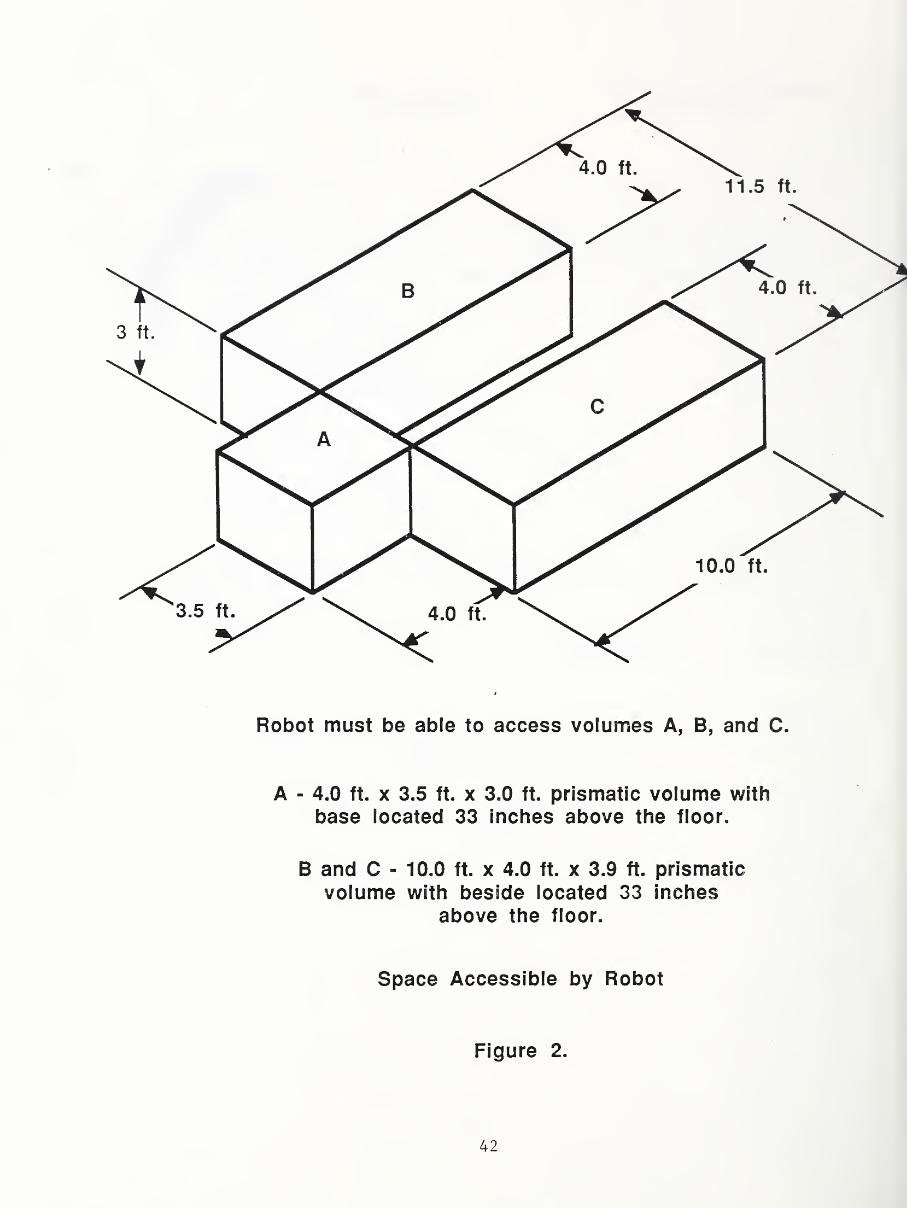
Robot must be able to access volumes A, B, and C.
A - 4.0 ft. x 3.5 ft. x 3.0 ft. prismatic volume with
base located 33 inches above the floor.
B and C - 10.0 ft. x 4.0 ft. x 3.9 ft. prismatic
volume with beside located 33 inches
above the floor.
Space Accessible by Robot
Figure 2.
42

KXM NBS-I 14A REV 11441
U.S. DEPT. OF COMM.
BIBLIOGRAPHIC DATASHEET (See instructions)
l. PU BL1LA FIUN UKREPORT NO.
NISTIR 88-3811
l. Pertorming Urgan. Report No. 3. Publ ication Date
JUNE 19894.
TITLE AND SUBTITLE
Recommended Technical Specifications for Procurement of a Turning Workstation5.
AUTHOR(S)
Kang B. Lee
6.
PERFORMING ORGANIZATION (If joint or other than NBS, see in struction s)
NATIONAL BUREAU Of STANDARDSU.S. DEPARTMB4T Of COMMBtCEGAITHERSBURG, MD 20B99
7. Contract/Grant No.
8. Type of Report & Period Covered
9. SPONSORING ORGANIZATION NAME AND COMPLETE ADDRESS (Street. City. State, ZIP)
U. S. Navy Manufacturing Technology Program
10.
SUPPLEMENTARY NOTES
T Document describes a computer program; SF-185, FIPS Software Summary, is attached.
11.
ABSTRACT (A 200-word or less factual summary of most significant in formation. If document includes a si gmficantbi bliography or literature survey, mention it here)
This manual serves as a technical guide to the specifications required to procure
commercially available, major components such as a turning center and a robot
system for an automated turning workstation.
12.
KEY WORDS (S/x to twelve entries; alphabetical order; capitalize only proper names; and separate key words by semicolons;
Turning center specification, robot specification, performance test, procurement.
13. AVAILABILITY
[ y )
Uni imited
| |
For Official Distribution. Do Not Release to NTIS
| |
Order From Superintendent of Documents, U.S. Government Printing Office, Washington,20402.
y~ Order From National Technical Information Service (NTIS), Springfield, VA 22161
14. NO. OFPRINTED PAGES
DC48
15. Price
$12.95
USCOMM-OC 85-6006

• '