recon dodge cab light install guide - gorecon.com · -now place the cab light on the mark you made...
TRANSCRIPT

1 | P a g e Here I Will Explain How To Install Recon Cab Lights In A 3rd Gen Dodge Ram.
*Now, There Are Many Ways of Installing Them, Including Wiring Methods, Wiring Connectors, And Other Variables - In This Install I Will Show You My Method of Install. The “How to” Writer Is Not Responsible for the Information Following Instructions. This Guide is Provided Simply for Concepts and Ideas on How to Install Cab Lights.
- Go Over The Equipment You Received - Look For Blemishes, or Missing Parts. You Should Have:
• 5 Marker Lights • 10 Screws & 10 Rubber Washers

2 | P a g e
Tools Required:
A Good Assortment of Hand Tools is Recommended, Required Hand tools are as Followed:
• Wet Erase Marker • Cordless Drill • 2 Drill Bit Sizes - 1/8" and 1/4 (or 3/8") • Phillips Bit • Wire Strippers & Crimper's • DC Voltage Meter • Tape Measures & Ruler (Straight Edge) • Screw Drivers Phillips & Flat Head (Small Flat Head) • 10mm Socket (Deep well Preferred) • T20 Torx & T50 Torx • Electrical Tape • Stranded LV Wire (Spec'd At Least At 20 Amp) • Choice of Connectors +/- Soldering Tools • Step Ladder (x2 If Possible)

3 | P a g e
On To The Tear Down. It Is Not Required, but Disconnecting Your Batteries Negative Cable Is Recommended Start by Removing the Front Driver and Passenger Pillars. -On The Grab Handle Use The Small Flat Head Screw Driver To Pop Open The Caps
-Use The 10 mm Socket The Remove The (2) Bolts on The Driver & Passenger Side -With The Bolts Out, Pull On The Handle -The Clips Will Unclip - The Pillar Then Can Be Removed Remove The Driver and Passenger Visors -Unclip The Visor, On the Hinge Side of The Visors Remove The (3) T20 Torx Bolts on Each Side
-With The Bolts Out, Pull Down On The Visor Until It Unclips - The Visor Then Can Be Removed. -The Stationary Visor Clips Will Not Be Detached From The Headliner, They Simply Pull Down and Unclip From the Roofs Structure

4 | P a g e Remove Overhead Display W/ Lights -Remove The Light Covers (2) With Flat Head Screwdriver (Pry Till' They Unclip, Gently)
-Remove The (2) Silver Screws, 1 In Each Light Opening -Now The Console Is Held Up By Two Clips In The Front Most Section, Pull Down Gently
-With The Console Down Remove The (2) Wiring Clips (Black & White), The Console may Now Be Removed
-Unscrew The (2) Black Phillips Screws Used To Connect The Black Bracket To Roof Structure - This Will Not Be Removed From The Vehicle

5 | P a g e Remove Door Pillar & Seat Belt Bolt -With Flat Head Screwdriver Pop Off Caps on Rear Grab handle - Driver & Passenger
-Remove (2) 10mm Bolts On Each Sides Grab Handle -With Flat Head Screwdriver Unclip Upper Seat Belt Cover and Remove T50 Torx Bolt (Will Need Encouragement)
-Removed Handle From Pillar - Remove Pillar by Pulling Edges Out Of Door Trim Groves - Pillar and Handle Now Can Be Removed
At This Point Your Headliner Will Now Be Pulled Down To A Workable Depth

6 | P a g e
Roof Layout and Drilling With Proper Measurement, And A Confident Installer, Drilling The 15 Holes Should Not Be An Issue -This Part may become Tricky, A Good Understanding Before Measuring Will Be Needed. - The Marking Device I Used Was A Black WET Erase Marker (Will Clean Up Nice With Water When Done) Setting Up Measuring Device -Layout One Tape Measure Across The Roof of The Cab From Door To Door & Close Doors Onto Tape Measure (This Will Hold It In Place)
-As You Can See With The Doors CLOSED The Tape Measure Starts At 3" - That Is Now 0" (Every Measurement Will Be Minus 3") and Ends At 56" -Now, To Get The Tape Even Front To Back - Measure 6" Up From The Windshield on Both Sides and Mark With The Wet Erase Marker. We Can Now Measure Precisely At 6" Above The Win shield.
-With Another Tape Measure, Run It Across Door To Door (Like The Other One), Only Place This One Right Where The Windshield Meets The Roof. Now Close The Door - This Tape Should Also Start At 3" To Prevent Confusion.
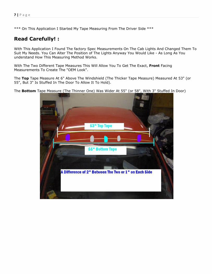
7 | P a g e *** On This Application I Started My Tape Measuring From The Driver Side *** Read Carefully! : With This Application I Found The factory Spec Measurements On The Cab Lights And Changed Them To Suit My Needs. You Can Alter The Position of The Lights Anyway You Would Like - As Long As You understand How This Measuring Method Works. With The Two Different Tape Measures This Will Allow You To Get The Exact, Front Facing Measurements To Create The "OEM Look". The Top Tape Measure At 6" Above The Windshield (The Thicker Tape Measure) Measured At 53" (or 55", But 3" Is Stuffed In The Door To Allow It To Hold). The Bottom Tape Measure (The Thinner One) Was Wider At 55" (or 58", With 3" Stuffed In Door)

8 | P a g e -That Being Said The Right Most Cab Light and The Left Most Cab Light Will Be At 5.5" (On Center) At The Top Measuring Tape, and 6.5" at The Bottom Measuring Tape.
-Mark Your Spot by Both Tape Measures, on Both Sides For The 1st and 5th Cab Light
-The 3rd Cab Light (The Center One) Will Measure At Half Of The Roof
• 53" On The Top Tape = 26.5" • 55" On The Bottom Tape = 27.5"

9 | P a g e Now The 2nd and The 4th Cab Light Can Be Measured 3 Ways:
• 12.5" From The 1st and 5th Cab Light Mark (Top Tape and Bottom Tape) • 18" From Door To Door (19" on the Bottom Tape) • or 8.5" From The Center Cab Light Mark
-The Simple Layout Is As Follows:
Marking Drilling Holes: -The Best Length (I Found Anyway) From the Windshield To The FRONT of The Cab Light Was 4" For The Center (3) Cab Lights and 6" For The Outside (2) Cab Lights. This Will Allow The Curve of The Light To Fit The Cab (To Prevent Leaks and Bowing of The Roof) -Now You Should Have Two Sets of Marks High and Low For The Placement of The Cab Lights - Remove The Tape Measures and Connect The Marks Using A Straight Edge or Ruler W/ The Wet Erase Marker, At Least 12" Up the Roof Perpendicular To the Tape Measure. (I Did Not Have A Tape Measure and Used A Piece of Sheet Metal)
-On the Line You Just Made, From The Windshield Mark Up 4" For The Center 3 Lines and 6" For The Outside 2 Lines (This Will be The Front Most Point of The Cab Light, Not The Screw Hole!)
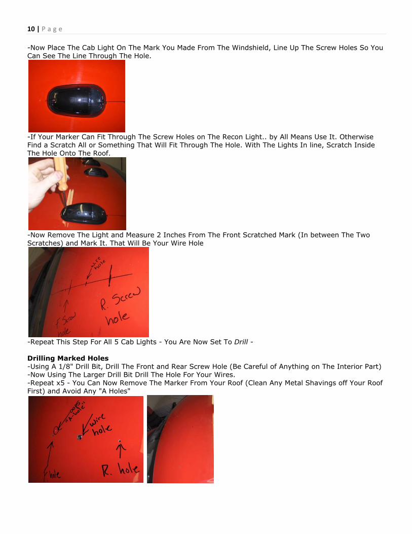
10 | P a g e -Now Place The Cab Light On The Mark You Made From The Windshield, Line Up The Screw Holes So You Can See The Line Through The Hole.
-If Your Marker Can Fit Through The Screw Holes on The Recon Light.. by All Means Use It. Otherwise Find a Scratch All or Something That Will Fit Through The Hole. With The Lights In line, Scratch Inside The Hole Onto The Roof.
-Now Remove The Light and Measure 2 Inches From The Front Scratched Mark (In between The Two Scratches) and Mark It. That Will Be Your Wire Hole
-Repeat This Step For All 5 Cab Lights - You Are Now Set To Drill - Drilling Marked Holes -Using A 1/8" Drill Bit, Drill The Front and Rear Screw Hole (Be Careful of Anything on The Interior Part) -Now Using The Larger Drill Bit Drill The Hole For Your Wires. -Repeat x5 - You Can Now Remove The Marker From Your Roof (Clean Any Metal Shavings off Your Roof First) and Avoid Any "A Holes"

11 | P a g e - You Are Now Set To Wire - Wire and Cab Light Install -There Are Many Ways To Wire to Your Cab Lights. There Is No Harm Is Using Wire Nuts, Butt Connectors, or The Method I Chose - Soldering. I Decided To Make 2 Wiring Harness's, One For The Negative, and One For The Power. Building The Harness -Start off By Cutting A Piece of Wire Long Enough To Reach From The Driver Side Cab Light to The Bottom of The Passenger Side Pillar -Put One End of The Wire In The "Wire Hole" on The Roof Drivers Side -Now With Your Marker, Stretch Out The Wire Under Your Roof (Above The Headliner) and Mark On The Wire Where Each Cab Light Hole Is. (4 Marks) -Where Your Marks Are, Cut Out A Section of The Insulation To Expose The Bare Wire.
-Now Cut 4 Strips of Wire Approx. 6" Long, and Strip The Ends. -Twist The Strips around The Splices on The Main Length
-Now Solder The Wires Together To Create A SURE Connection

12 | P a g e -Tape The Wires To Prevent any Grounding Issues
-Now You have A Tree Branch Like Harness to Wire Your Lights Up, Repeat These Steps To Create A Negative Harness
Wiring The Cab Lights To Your Harness -Pull Each Branch of The Power Harness Through The Designated Wire Holes In Roof
-With the RECON Light, Snip The Connector Off and Strip The Wires

13 | P a g e -Connect Each Recon To The Power Wire First
-Push The Power Wire Through Roof, and Pull The Ground Wire Up and Connect.
-Push The Ground Wire Back Through Roof
VERY IMPORTANT STEP!: Sealing And Securing Your Recons -Using Waterproof Silicone or RTV, Goop Each of The 15 Holes With a Liberal Amount of Goop
-With The Recon Seated, Use The Supplied Screws and Washers - Use The 1/8 Pre Drilled Holes To Secure It To Your Roof DO NOT OVER TIGHTEN! Slowly Screw In Recon Lights Until A Firm Seal Is Created.

14 | P a g e
-Apply Some Goop Under The Roof Also
-With The Wires Ran Into Cab, Be Sure To Tape and Secure All Connections to Prevent Any Lose or Jarred Connections During The Re-Install of The Headliner.
-Run The Harness Wires To The Passenger Side Pillar. You May Now Push Up The Headliner A Pop Up The Clips For The Visor - This Will Raise Your Headliner Out Of The Way.

15 | P a g e Connecting To Your Factory Power and Ground This Step Will Range From Each 3rd Gen Model Ram, A Voltage Meter Is Great Tool To Locate The Factory Cab Light Wires Finding The factory Harness: -On The Passenger Side Pillar, Locate The Factory Harness That Supplies Power To You Cab Lights. (Mounted on Pillar)
-Using Your Voltage Meter Determine Which Wire Is Your Cab Lights (Power Only Supplied When Running Lamps Are On) This Model Was The Top Two Wires (black = Ground, Grey/white = Power)
-Snip Only The Wires You Need To Supply Your Cab Lights Wiring To Factory Power and Ground -With The Two Wires Exposed, Strip The Wires And Crimp Insulated Disconnect Connectors (Any Connectors Will Suffice)
-Connect The Connectors Together - Tape Any Exposed Areas To Prevent Grounding -Re Clip The Rest Of The Harness Back To Pillar, And Tuck Wires Into Dash.

16 | P a g e Reinstall Headliner and Test You Can Now Test Your Lights To Make Sure All Connections Are Made and Lights Are Working Properly. If All Is Well, Clean Your Wires Up With Zip Ties & Tape. Then Re-Install All the Components You Removed To Drop Your Head Liner You Are Now Done! Enjoy