reconstructing human joint motion with computational …
TRANSCRIPT
19
Reconstructing Human Joint Motion with Computational Fabrics
RUIBO LIU, Department of Computer Science, Dartmouth CollegeQIJIA SHAO, Department of Computer Science, Dartmouth CollegeSIQI WANG, Department of Computer Science, Shanghai Jiao Tong UniversityCHRISTINA RU, Department of Computer Science, Dartmouth CollegeDEVIN BALKCOM, Department of Computer Science, Dartmouth CollegeXIA ZHOU, Department of Computer Science, Dartmouth College
Accurate and continuous monitoring of joint rotational motion is crucial for a wide range of applications such as physicalrehabilitation [6, 85] and motion training [22, 54, 68]. Existing motion capture systems, however, either need instrumentationof the environment, or fail to track arbitrary joint motion, or impose wearing discomfort by requiring rigid electrical sensorsright around the joint area. This work studies the use of everyday fabrics as a flexible and soft sensing medium to monitor jointangular motion accurately and reliably. Specifically we focus on the primary use of conductive stretchable fabrics to sense theskin deformation during joint motion and infer the joint rotational angle. We tackle challenges of fabric sensing originatedby the inherent properties of elastic materials by leveraging two types of sensing fabric and characterizing their propertiesbased on models in material science. We apply models from bio-mechanics to infer joint angles and propose the use of dualstrain sensing to enhance sensing robustness against user diversity and fabric position offsets. We fabricate prototypes usingoff-the-shelf fabrics and micro-controller. Experiments with ten participants show 9.69◦ median angular error in trackingjoint angle and its sensing robustness across various users and activities.
CCS Concepts: • Human-centered computing → Ubiquitous and mobile computing systems and tools; Ambientintelligence.
Additional Key Words and Phrases: smart fabric/textile, fabric/textile sensing, joint motion sensing
ACM Reference Format:Ruibo Liu, Qijia Shao, Siqi Wang, Christina Ru, Devin Balkcom, and Xia Zhou. 2019. Reconstructing Human Joint Motionwith Computational Fabrics. Proc. ACM Interact. Mob. Wearable Ubiquitous Technol. 3, 1, Article 19 (March 2019), 26 pages.https://doi.org/10.1145/3314406
1 INTRODUCTIONHuman body joints are essential for actuating bodymotion. Accurate and continuousmonitoring of their rotationalmovement is critical for physical rehabilitation [6, 85], motion training/coaching [22, 54, 68], sports analytics [48],human-robot or human-computer interactions [20, 47]. For rehabilitation patients with joint injuries or chronicjoint pains, day-to-day measurement of joint’s angular motion helps doctors assess the effectiveness of medical
Authors’ addresses: Ruibo Liu, Department of Computer Science, Dartmouth College, 9 Maynard St, Hanover, NH, 03755, [email protected]; Qijia Shao, Department of Computer Science, Dartmouth College, [email protected]; Siqi Wang, Department ofComputer Science, Shanghai Jiao Tong University, [email protected]; Christina Ru, Department of Computer Science, Dartmouth College,[email protected]; Devin Balkcom, Department of Computer Science, Dartmouth College, [email protected];Xia Zhou, Department of Computer Science, Dartmouth College, [email protected].
Permission to make digital or hard copies of all or part of this work for personal or classroom use is granted without fee provided thatcopies are not made or distributed for profit or commercial advantage and that copies bear this notice and the full citation on the firstpage. Copyrights for components of this work owned by others than ACM must be honored. Abstracting with credit is permitted. To copyotherwise, or republish, to post on servers or to redistribute to lists, requires prior specific permission and/or a fee. Request permissions [email protected].© 2019 Association for Computing Machinery.2474-9567/2019/3-ART19 $15.00https://doi.org/10.1145/3314406
Proc. ACM Interact. Mob. Wearable Ubiquitous Technol., Vol. 3, No. 1, Article 19. Publication date: March 2019.

19:2 • R. Liu et al.
and physical treatments, since joint and muscle repair takes long enough that it is impractical for expert therapiststo remain with patients at all times; for students learning precise motions from instructors in the educationalcontext (e.g., athletic coaching, yoga training, learning a complex surgical procedure), monitoring joint anglesallows instructors to analyze detailed joint movements and provide fine-grained corrections and feedback.All these applications demand joint motion sensing systems that are portable, comfortable for long-time
wear, and capable of sensing subtle motion. Existing technologies for motion capture, however, still fall short inmeeting these requirements. High-end systems such as VICON [87] or Kinect require heavy instrumentation ofthe environment (e.g., setting up multiple infrared cameras). More portable systems either achieve coarse sensinggranularity by classifying a limited set of gestures/poses and thus cannot track arbitrary motion, or requireusers to constantly wear rigid electrical sensors right around the joint area [18, 75, 91], where such placementinflexibility often causes the system burdensome to wear.In this work we consider the use of everyday fabrics as an unobtrusive sensing medium to continuously and
accurately monitor joint angular motion. Requiring neither infrastructure support nor rigid electrical sensorson the joint, our approach relies on fabrics/textile alone, as a soft and natural sensing layer around joints, toreconstruct the angles of body joints at a fine granularity. While the concept of e-textile has been proposed inprior studies for various applications, prior works either offer coarse sensing capabilities [49, 58, 62, 82] or stillrequire embedding electronics into textiles by using textile as a substrate for attachment of sensors. We aim toadvance the state-of-the-art by achieving qualitative advances in sensing capability and reliability, and moreimportantly, by focusing on the use of off-the-shelf, low-cost (e.g., $50) fabrics alone for motion sensing withoutextra electrical sensors. Such a minimalist sensing approach renders the sensing system comfortable to wear,low-power, and low-cost.
Specifically, we study primarily the use of conductive stretchable fabrics with knitted structures. As shown inFigure 2(b), a knitted fabric is constructed by a continuous loop of yarns. Made of conductive stretchable threads,the knitted fabric reacts to different levels of strain with varying resistance. The change in resistance is caused byalterations of the yarns’ contact points and contact pressure under tension [32]. This property can be exploitedto sense body joint motion, where we wrap a joint with conductive stretchable fabrics (also serving as a jointprotective wrap commonly worn during exercises for joint protection). Joint rotation and muscle movementcause skin deformation and thus strain of the fabric. By continuously monitoring the fabric’s resistance, we caninfer the muscle strain caused by the current joint motion, and thus recover the joint angle. The system onlyrequires a micro-controller fetching data on fabric resistance through conductive threads. The micro-controllercan be placed away from the joint for greater comfort flexibility. As an example, it can be embedded into a buttonto hide its appearance and it can be easily detached when necessary.To realize this conceptually simple idea as a practical system providing accurate and robust motion sensing,
we are confronted with several challenges. First, with off-the-shelf stretchable fabrics, the resistance changeand the level of strain do not exhibit a one-to-one mapping, and even worse, their relationship depends onthe type of motion (e.g., flexion/loading or extension/unloading), caused by the hysteresis intrinsic to elasticmaterials. It results in ambiguities in inferring skin deformation solely based on the observed changes in fabricresistance. Second, fabric as a strain sensor does not provide a stable output even under a constant strain. This isa phenomenon common in stretchable materials and referred to as the stress relaxation in material science. Suchrelaxation further increases the ambiguity in inferring skin deformation and leads to errors that accumulate overtime. Third, even with perfect derivation of skin deformation, inferring the actual joint angle is still nontrivial.For one, bone shape and soft tissue distribution differ significantly across users. Additionally, joint motion canlead to the sensing fabrics sliding subtly around the joint. Both individual differences and the motion artifact ofthe sensing fabrics pose challenges in achieving robust motion sensing in practice.We address the above challenges as follows. To disambiguate motion states, we add a small piece of pressure
fabric to augment the primary sensing fabric (i.e., strain sensors). The pressure fabric senses the pressure from
Proc. ACM Interact. Mob. Wearable Ubiquitous Technol., Vol. 3, No. 1, Article 19. Publication date: March 2019.
Reconstructing Human Joint Motion with Computational Fabrics • 19:3
the joint to the fabric during motions. Although it alone cannot provide precise sensing of subtle motion, it cansteadily differentiate coarse motion states: flexion, extension, or the motionless state. We characterize the strainfabric’s resistance change in different motion states, and apply models from material sciences to compensate forthe stress relaxation during the motionless state. Finally, we leverage models in the literature of bio-mechanicsto characterize the geometric relationship between skin deformation and joint angle. To deal with individualdifferences and motion artifact of the sensing fabrics, we place two straps of strain fabrics as dual sensors abovethe joint. We consider the differences of the stretch lengths of these two strain fabrics, which cancel out theimpact of the body part thickness or slight offset of fabric positions.
Using the elbow joint as an example, we fabricate prototypes in two sizes (27/20.5 cm lower-elbow perimeter,31/23 cm upper-elbow perimeter) using off-the-shelf fabrics and micro-controller (Adafruit Flora). We place strainfabrics and pressure fabrics in separate layers to enhance their sensing resilience and sensitivity. Inelastic fabricsare used as reference resistor for the micro-controller to monitor the resistance change of strain and pressurefabrics, where micro-controller and sensing fabrics are connected via conductive threads. we test our prototypeswith ten participants to examine sensing accuracy and robustness. We also seek participants’ feedback on thewearing comfort. We summarize our key findings as below:
• The system reconstructs elbow joint angles with a median error of 9.69◦ across users with different arm sizes,under motions with various speeds and magnitudes;• The sensing performance is robust against slight displacement (up to 1 cm) of the sensing fabrics around thejoint, and the system allows gentle hand wash with minor degradation (7.64◦) in sensing accuracy after wash;• Participants generally rate the prototypes comfortable to wear and flexible to adapt to various motions.
2 BACKGROUND ON FABRIC SENSINGFabric as a sensor presents numerous benefits, as it is soft, light, flexible, and thus easy to wear even duringexercises. In particular, our study considers off-the-shelf stretchable textile made of conductive threads as ourprimary sensing fabric. The sensing ability of such fabrics stems from their knitted micro-structures of the yarns,where an external strain causes changes in the number of contact points and contact pressure, resulting intochanges in the contact resistance of the fabric [12, 32, 64, 80]. We next experimentally examine the property ofsuch fabrics and their sensing capability.
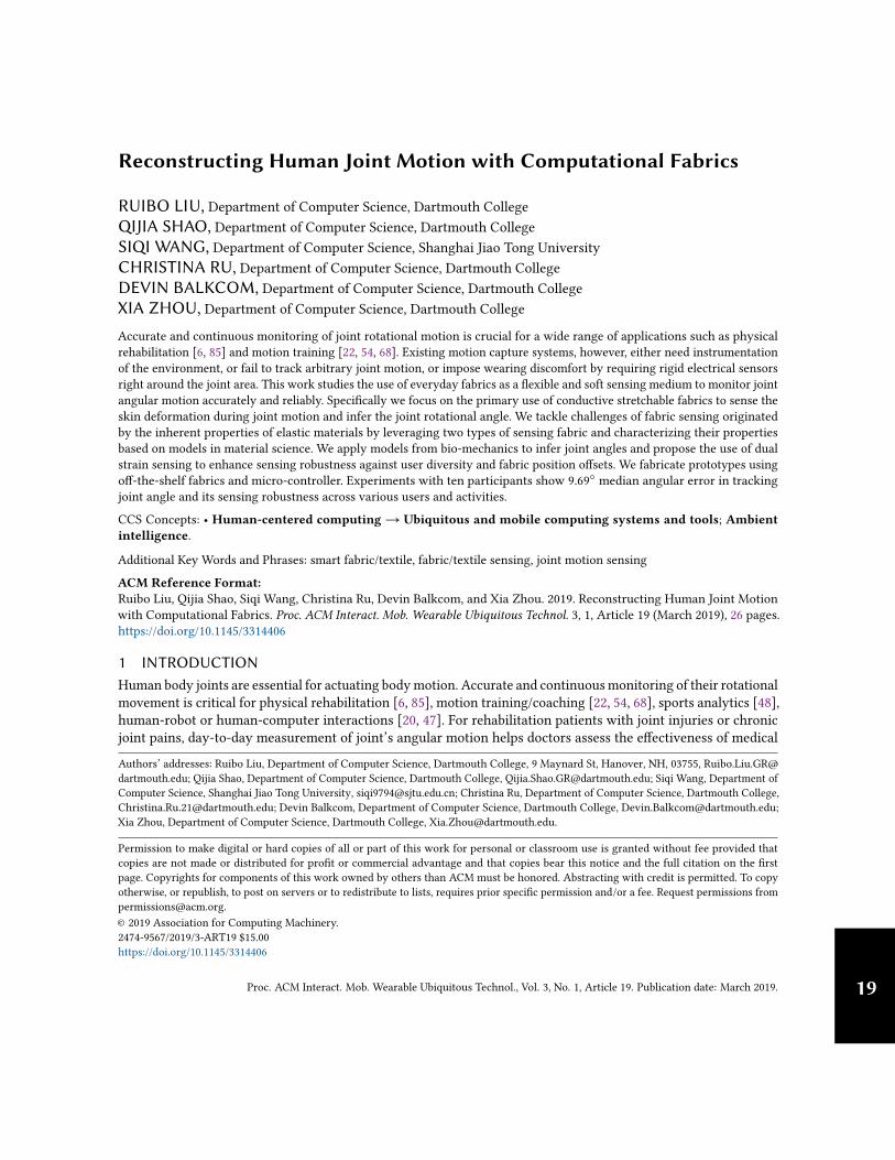
Experimental Validation. We test an off-the-shelf stretchable conductive fabric (LessEMF #A321) [34]. With
Created
byVecto
rsMa
rket
fromthe N
oun P
roject
Createdby
VectorsM
arket
fromtheNo
unProject
Vcc (3.3V)
MCU
PC
GND
Air Pump GripAfter stretched
Instron 4442
Rref
R1 R1 R2
U1 U2
Ref Resistance
LessEMF #A321
Fig. 1. Test platform configuration
76%Nylon and 24% elastic fiber, it can be stretched by up to 100%along its length/course direction and 60% along its width/waledirection. Its yarns are plated with a thin silver layer offeringgreat conductivity. We cascade the test fabric with a fixed-valuereference resistance. We use a micro-controller to measure thevoltage on the test fabric to monitor its resistance change undervarious levels of strain. To systematically apply various levelsof strain, we use a professional tensile test machine (Instron4442). Figure 1 illustrates the overall setup. We evaluate fabric’sresistance change via the metric of resistance change ratio r∆R =(R2 − R1)/R1, where R1 and R2 denote the original and currentresistance, respectively. With the original voltage as U1 andcurrent voltage asU2, r∆R can be computed as:
r∆R =R2 − R1
R1=VccU2 −U1U2
VccU1 −U1U2− 1, (1)
Proc. ACM Interact. Mob. Wearable Ubiquitous Technol., Vol. 3, No. 1, Article 19. Publication date: March 2019.

19:4 • R. Liu et al.
(a) Overall trend
Fiber Slipping Peak Yarn Stretching
(b) Various phases during a stretchFig. 2. The change of fabric resistance as the fabric is stretched. Resistance sharply increases due to the decrease in yarncontact points during fiber slipping, and then gradually decreases under increasing contact pressure during yarn stretching.
where Vcc is the power supply voltage from the micro-controller.Figure 2(a) plots the resistance change ratio as a 15 cm × 3 cm fabric is stretched along its course direction.
We also plot the stress on the fabric recorded by Instron. We obtain two main observations. First, the fabricis very sensitive to motion, where even millimeter-level stretches cause noticeable changes in resistance (e.g.,2cm stretch leads to 60% resistance change). It provides basis for sensing fine-grained motion. Second, as thestrain grows, the change in fabric resistance is not monotonic; rather, it undergoes a sharp increase, followed bya gradual decline. We observe similar patterns consistently across various test runs and across other types ofstretchable fabrics we have tested. This pattern can be explained by examining how contact points and contactpressure are altered under strain. Based on the Holm’s theory [32], the contact resistance of a conductive fabric isinversely proportional to the number of contact points and the contact pressure. In the beginning when the fabricis being slightly stretched, the stress on the fabric is not evident and the change in the number of contact pointsdominates the resistance change. The low level of strain only causes fiber slipping within air gaps and formingtighter block structure. As a result, the number of contact points decreases, leading to an increase in contactresistance. As the fabric is further stretched under higher levels of strain, the stress on the fabric becomes thedominant factor that changes the resistance. Since there is no more space for yarns to form blocks, the number ofcontact points stays constant. The growing inner stress among yarns leads to the decline of the contact resistance.Figure 2(b) illustrates fabric’s micro-structure during different phases of the process.
We further test the resistance change as we stretch the fabric in the wale direction. We cut two pieces of fabricsin the same size (15cm × 3cm), one with course direction along its length and the other with wale direction alongits length. We stretch both fabrics to 30% of its original length and plot the resistance change ratios in Figure 3(a).We observe that resistance change exhibits a similar trend yet with distinct details: stretch in the course directionleads to more significant changes in resistance (over 100%), while that in the wale direction leads to only around5% change in the resistance. Figure 3(b) and 3(c) show the microscope images of each fabric under 30% strain.
0
1
0 10 20 30 40
R C
hange R
atio
Extension(mm)
WaleCourse
(a) Impact of stretch direction
Course
30% strain
(b) 30% strain in the course direction
Wale
30% strain
(c) 30% strain in the wale direction
Fig. 3. Resistance change of stretchable conductive fabric when it is stretched along its wale or course direction (a). (b) and(c) are microscope images on fabric’s micro-structure under 30% strain along the course and wale direction, respectively.
Proc. ACM Interact. Mob. Wearable Ubiquitous Technol., Vol. 3, No. 1, Article 19. Publication date: March 2019.
Reconstructing Human Joint Motion with Computational Fabrics • 19:5
0
1
0 15 30
R C
ha
ng
e R
atio
Extension(mm)
15cm * 1cm15cm * 2cm15cm * 3cm
(a) Varying width
0
1
0 15 30
R C
ha
ng
e R
atio
Extension(mm)
12cm * 2cm15cm * 2cm18cm * 2cm
(b) Varying length
Fig. 4. Impact of fabric size configuration on its sensitivity to stretch.
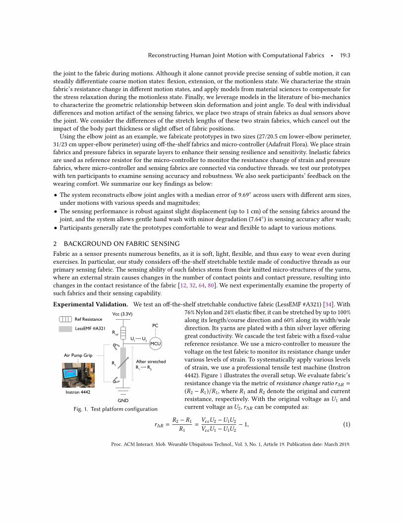
We also examine the impact offabric’s size ratio on its sensitivityto strain. Figure 4 compares variousfabrics in various size configurationswhen they are stretched in the coursedirection. We observe that increasesin the width result into higher peaks,because more yarn blocks are formed,leading to fewer contact points andlarger increase in resistance. On theother hand, under a fixedwidth, longerfabrics have more air gaps in the stretching direction and thus need more strain to reach the peak, leading to thepeak occurred under larger stretch lengths. Additionally, we observe that a thinner fabric (1-cm width) has morehigh-frequency noise in its signal response. We hypothesize that the thinner fabric has weaker fiber strength,making it harder to keep a stable structure and stable resistance value. Overall, wider and longer fabrics are morepreferable for sensing purposes.
Summary. Our experiments results validate that off-the-shelf stretchable conductive fabrics are sensitive tomotion when they are stretched along the course direction. Even millimeter-level stretches lead to noticeablechanges in resistance, providing basis for the fabric to sense skin deformation caused by subtle joint motion. Underincreasing strain, the change in fabric’s resistance is non-monotonic, starting with a sharp increase followed by agradual decline. Wider and longer fabrics provide more stable, substantial change in resistance under strain.
3 CHALLENGES IN FABRIC SENSINGWhile prior results are promising, fabric as a sensor also presents numerous challenges, especially for the purposeof accurately and robustly inferring joint angles. We elaborate on the challenges as follows.
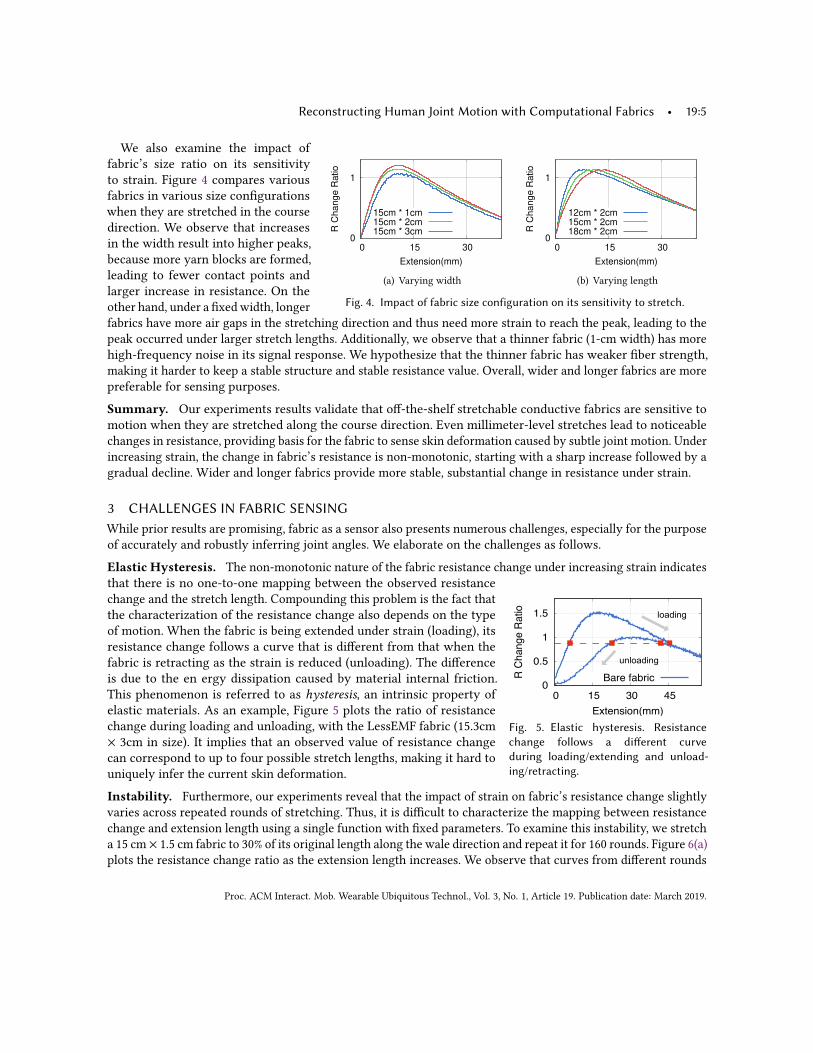
Elastic Hysteresis. The non-monotonic nature of the fabric resistance change under increasing strain indicates
0
0.5
1
1.5
0 15 30 45
RCh
ange
Ratio
Extension(mm)
Bare fabric
loading
unloading
Fig. 5. Elastic hysteresis. Resistancechange follows a different curveduring loading/extending and unload-ing/retracting.
that there is no one-to-one mapping between the observed resistancechange and the stretch length. Compounding this problem is the fact thatthe characterization of the resistance change also depends on the typeof motion. When the fabric is being extended under strain (loading), itsresistance change follows a curve that is different from that when thefabric is retracting as the strain is reduced (unloading). The differenceis due to the en ergy dissipation caused by material internal friction.This phenomenon is referred to as hysteresis, an intrinsic property ofelastic materials. As an example, Figure 5 plots the ratio of resistancechange during loading and unloading, with the LessEMF fabric (15.3cm× 3cm in size). It implies that an observed value of resistance changecan correspond to up to four possible stretch lengths, making it hard touniquely infer the current skin deformation.
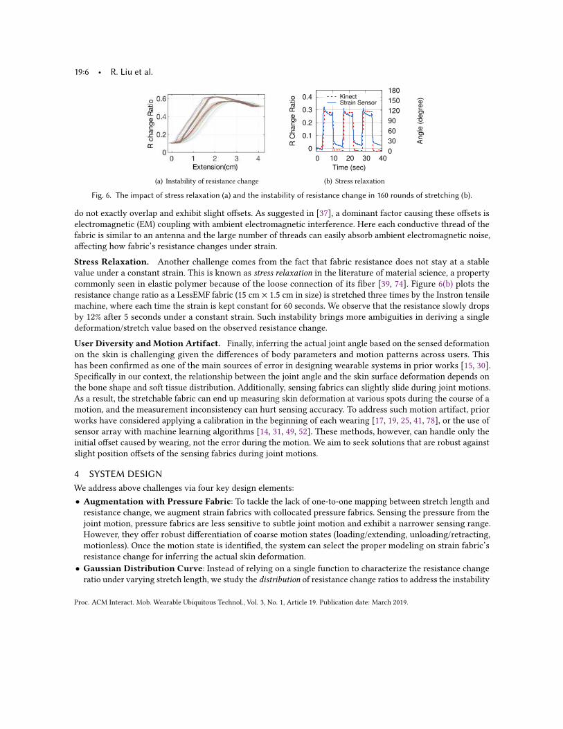
Instability. Furthermore, our experiments reveal that the impact of strain on fabric’s resistance change slightlyvaries across repeated rounds of stretching. Thus, it is difficult to characterize the mapping between resistancechange and extension length using a single function with fixed parameters. To examine this instability, we stretcha 15 cm × 1.5 cm fabric to 30% of its original length along the wale direction and repeat it for 160 rounds. Figure 6(a)plots the resistance change ratio as the extension length increases. We observe that curves from different rounds
Proc. ACM Interact. Mob. Wearable Ubiquitous Technol., Vol. 3, No. 1, Article 19. Publication date: March 2019.
19:6 • R. Liu et al.
(a) Instability of resistance change
0
0.1
0.2
0.3
0.4
0 10 20 30 40 0
30
60
90
120
150
180
R C
hange R
atio
Angle
(degre
e)
Time (sec)
KinectStrain Sensor
(b) Stress relaxation
Fig. 6. The impact of stress relaxation (a) and the instability of resistance change in 160 rounds of stretching (b).
do not exactly overlap and exhibit slight offsets. As suggested in [37], a dominant factor causing these offsets iselectromagnetic (EM) coupling with ambient electromagnetic interference. Here each conductive thread of thefabric is similar to an antenna and the large number of threads can easily absorb ambient electromagnetic noise,affecting how fabric’s resistance changes under strain.
Stress Relaxation. Another challenge comes from the fact that fabric resistance does not stay at a stablevalue under a constant strain. This is known as stress relaxation in the literature of material science, a propertycommonly seen in elastic polymer because of the loose connection of its fiber [39, 74]. Figure 6(b) plots theresistance change ratio as a LessEMF fabric (15 cm × 1.5 cm in size) is stretched three times by the Instron tensilemachine, where each time the strain is kept constant for 60 seconds. We observe that the resistance slowly dropsby 12% after 5 seconds under a constant strain. Such instability brings more ambiguities in deriving a singledeformation/stretch value based on the observed resistance change.
User Diversity and Motion Artifact. Finally, inferring the actual joint angle based on the sensed deformationon the skin is challenging given the differences of body parameters and motion patterns across users. Thishas been confirmed as one of the main sources of error in designing wearable systems in prior works [15, 30].Specifically in our context, the relationship between the joint angle and the skin surface deformation depends onthe bone shape and soft tissue distribution. Additionally, sensing fabrics can slightly slide during joint motions.As a result, the stretchable fabric can end up measuring skin deformation at various spots during the course of amotion, and the measurement inconsistency can hurt sensing accuracy. To address such motion artifact, priorworks have considered applying a calibration in the beginning of each wearing [17, 19, 25, 41, 78], or the use ofsensor array with machine learning algorithms [14, 31, 49, 52]. These methods, however, can handle only theinitial offset caused by wearing, not the error during the motion. We aim to seek solutions that are robust againstslight position offsets of the sensing fabrics during joint motions.
4 SYSTEM DESIGNWe address above challenges via four key design elements:• Augmentation with Pressure Fabric: To tackle the lack of one-to-one mapping between stretch length andresistance change, we augment strain fabrics with collocated pressure fabrics. Sensing the pressure from thejoint motion, pressure fabrics are less sensitive to subtle joint motion and exhibit a narrower sensing range.However, they offer robust differentiation of coarse motion states (loading/extending, unloading/retracting,motionless). Once the motion state is identified, the system can select the proper modeling on strain fabric’sresistance change for inferring the actual skin deformation.• Gaussian Distribution Curve: Instead of relying on a single function to characterize the resistance changeratio under varying stretch length, we study the distribution of resistance change ratios to address the instability
Proc. ACM Interact. Mob. Wearable Ubiquitous Technol., Vol. 3, No. 1, Article 19. Publication date: March 2019.
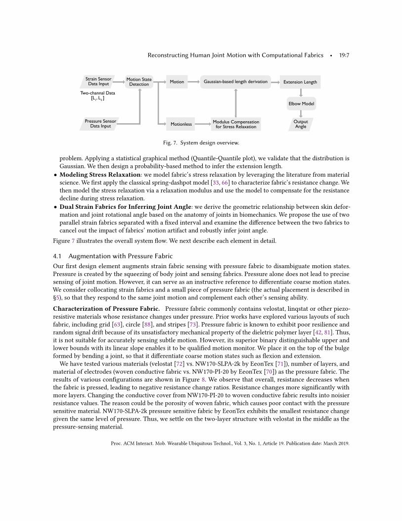
Reconstructing Human Joint Motion with Computational Fabrics • 19:7
Strain SensorData Input
Pressure SensorData Input
OutputAngleMotionless Modulus Compensation
for Stress Relaxation
Motion Extension LengthMotion StateDetection Gaussian-based length derivation
Elbow Model
Two-channal Data[L1, L2 ]
Fig. 7. System design overview.
problem. Applying a statistical graphical method (Quantile-Quantile plot), we validate that the distribution isGaussian. We then design a probability-based method to infer the extension length.• Modeling Stress Relaxation: we model fabric’s stress relaxation by leveraging the literature from materialscience. We first apply the classical spring-dashpot model [33, 66] to characterize fabric’s resistance change. Wethen model the stress relaxation via a relaxation modulus and use the model to compensate for the resistancedecline during stress relaxation.• Dual Strain Fabrics for Inferring Joint Angle: we derive the geometric relationship between skin defor-mation and joint rotational angle based on the anatomy of joints in biomechanics. We propose the use of twoparallel strain fabrics separated with a fixed interval and examine the difference between the two fabrics tocancel out the impact of fabrics’ motion artifact and robustly infer joint angle.
Figure 7 illustrates the overall system flow. We next describe each element in detail.
4.1 Augmentation with Pressure FabricOur first design element augments strain fabric sensing with pressure fabric to disambiguate motion states.Pressure is created by the squeezing of body joint and sensing fabrics. Pressure alone does not lead to precisesensing of joint motion. However, it can serve as an instructive reference to differentiate coarse motion states.We consider collocating strain fabrics and a small piece of pressure fabric (the actual placement is described in§5), so that they respond to the same joint motion and complement each other’s sensing ability.
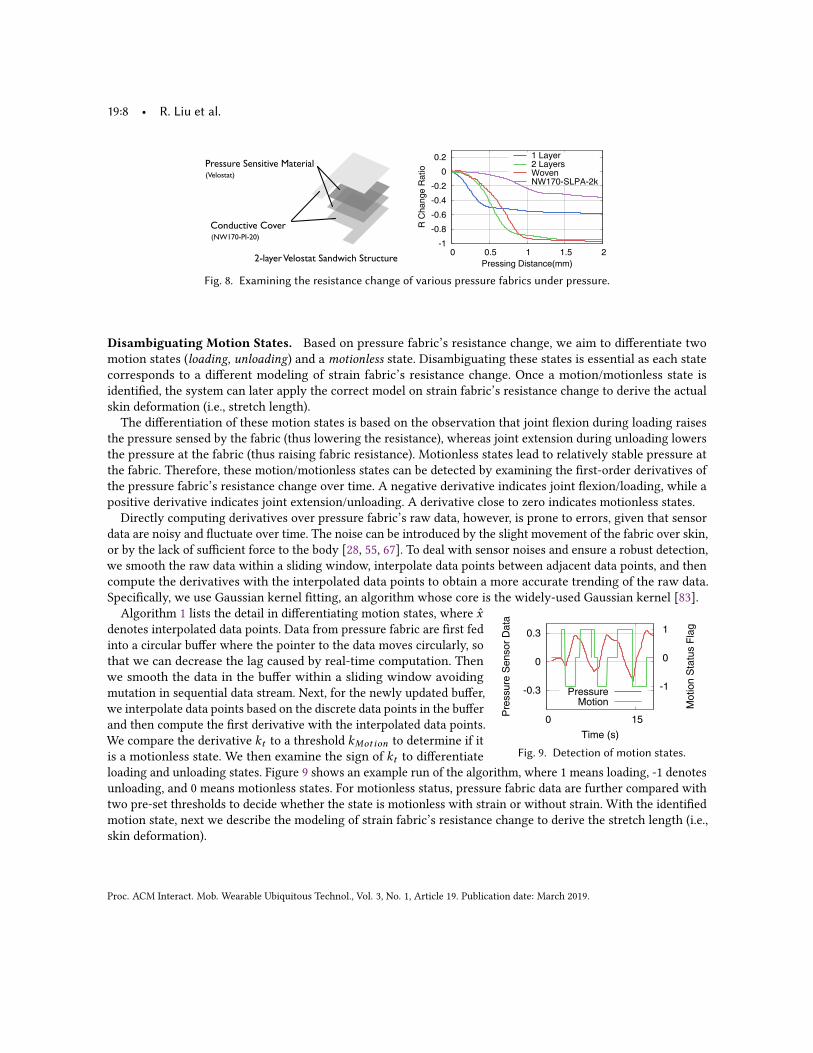
Characterization of Pressure Fabric. Pressure fabric commonly contains velostat, linqstat or other piezo-resistive materials whose resistance changes under pressure. Prior works have explored various layouts of suchfabric, including grid [63], circle [88], and stripes [73]. Pressure fabric is known to exhibit poor resilience andrandom signal drift because of its unsatisfactory mechanical property of the dieletric polymer layer [42, 81]. Thus,it is not suitable for accurately sensing subtle motion. However, its superior binary distinguishable upper andlower bounds with its linear slope enables it to be qualified motion monitor. We place it on the top of the bulgeformed by bending a joint, so that it differentiate coarse motion states such as flexion and extension.We have tested various materials (velostat [72] vs. NW170-SLPA-2k by EeonTex [71]), number of layers, and
material of electrodes (woven conductive fabric vs. NW170-PI-20 by EeonTex [70]) as the pressure fabric. Theresults of various configurations are shown in Figure 8. We observe that overall, resistance decreases whenthe fabric is pressed, leading to negative resistance change ratios. Resistance changes more significantly withmore layers. Changing the conductive cover from NW170-PI-20 to woven conductive fabric results into noisierresistance values. The reason could be the porosity of woven fabric, which causes poor contact with the pressuresensitive material. NW170-SLPA-2k pressure sensitive fabric by EeonTex exhibits the smallest resistance changegiven the same level of pressure. Thus, we settle on the two-layer structure with velostat in the middle as thepressure-sensing material.
Proc. ACM Interact. Mob. Wearable Ubiquitous Technol., Vol. 3, No. 1, Article 19. Publication date: March 2019.
19:8 • R. Liu et al.
2-layerVelostat Sandwich Structure
Conductive Cover
Pressure Sensitive Material(Velostat)
(NW170-PI-20)
Fig. 8. Examining the resistance change of various pressure fabrics under pressure.
Disambiguating Motion States. Based on pressure fabric’s resistance change, we aim to differentiate twomotion states (loading, unloading) and a motionless state. Disambiguating these states is essential as each statecorresponds to a different modeling of strain fabric’s resistance change. Once a motion/motionless state isidentified, the system can later apply the correct model on strain fabric’s resistance change to derive the actualskin deformation (i.e., stretch length).The differentiation of these motion states is based on the observation that joint flexion during loading raises
the pressure sensed by the fabric (thus lowering the resistance), whereas joint extension during unloading lowersthe pressure at the fabric (thus raising fabric resistance). Motionless states lead to relatively stable pressure atthe fabric. Therefore, these motion/motionless states can be detected by examining the first-order derivatives ofthe pressure fabric’s resistance change over time. A negative derivative indicates joint flexion/loading, while apositive derivative indicates joint extension/unloading. A derivative close to zero indicates motionless states.
Directly computing derivatives over pressure fabric’s raw data, however, is prone to errors, given that sensordata are noisy and fluctuate over time. The noise can be introduced by the slight movement of the fabric over skin,or by the lack of sufficient force to the body [28, 55, 67]. To deal with sensor noises and ensure a robust detection,we smooth the raw data within a sliding window, interpolate data points between adjacent data points, and thencompute the derivatives with the interpolated data points to obtain a more accurate trending of the raw data.Specifically, we use Gaussian kernel fitting, an algorithm whose core is the widely-used Gaussian kernel [83].
Fig. 9. Detection of motion states.
Algorithm 1 lists the detail in differentiating motion states, where x̂denotes interpolated data points. Data from pressure fabric are first fedinto a circular buffer where the pointer to the data moves circularly, sothat we can decrease the lag caused by real-time computation. Thenwe smooth the data in the buffer within a sliding window avoidingmutation in sequential data stream. Next, for the newly updated buffer,we interpolate data points based on the discrete data points in the bufferand then compute the first derivative with the interpolated data points.We compare the derivative kt to a threshold kMotion to determine if itis a motionless state. We then examine the sign of kt to differentiateloading and unloading states. Figure 9 shows an example run of the algorithm, where 1 means loading, -1 denotesunloading, and 0 means motionless states. For motionless status, pressure fabric data are further compared withtwo pre-set thresholds to decide whether the state is motionless with strain or without strain. With the identifiedmotion state, next we describe the modeling of strain fabric’s resistance change to derive the stretch length (i.e.,skin deformation).
Proc. ACM Interact. Mob. Wearable Ubiquitous Technol., Vol. 3, No. 1, Article 19. Publication date: March 2019.

Reconstructing Human Joint Motion with Computational Fabrics • 19:9
ALGORITHM 1: Detecting Motion States.Input: Data from pressure fabric xt .Output: Motion state: loading, unloading or motionless.repeat
Motion =Motionless;insert new data into the circular buffer bu f ;for each bu f updated by new data xt do
x̂ ← data interpolation;
Gaussian kernel (ϕ (x̂ ,xt ) = exp(−(x̂−xt )2
2b2
)) regression on the buffer bu f with kernel’s input scale b;
calculate the slope kt of current curve at data point xt ;if |kt | < kMotion then
continue;else
kt < 0→Motion = Loadinд;kt > 0→Motion =UnLoadinд;
endend
until no more data point comes in;
4.2 Derivation of Stretch LengthThe second design element aims to infer stretch length based on fabric’s resistance change. Given the instabilityof resistance change across repeated stretch cycles, we examine the distribution of resistance change ratios undera given stretch length across different rounds of stretch. Based on the characteristics of the distribution, wedesign a probability-based method to infer the stretch length. We next describe our analysis of the distributionand the probability-based method in detail.
Distribution Analysis. Earlier results indicate that the same level of strain (i.e., stretch length) can lead to
Fig. 10. Q-Q plot of sample data vs thestandard Gaussian distribution.
different resistance change ratios across repeated stretches (Figure 6(a)).We set out to analyze the distribution of resistance change ratios undera given stretch length. We stretch the fabric up to four centimeters 160rounds on the tensile test machine while sampling fabric’s resistancechange ratio at 100 Hz. In total, we obtained 400 data points in each roundand 160 data points (i.e., resistance change ratios) for each stretch length.At certain stretch length, we analyze the distribution of resistance changeratios. Using a statistical graphical method (Quantile-Quantile plot), ourresults reveal that the distribution is Gaussian. Quantile-Quantile (Q-Q)plot is a probability plot, which compares two probability distributions byplotting their quantiles against each other [86]. Here we fix one probability distribution as the standard Gaussiandistribution and compare each distribution with it. Figure 10 shows an example. We observe that the pointsdistribution is almost linear, suggesting that the distribution of resistance change ratios under a stretch length isGaussian [29].
Probability-Based Length Derivation. We exploit the Gaussian distribution of resistance change ratios foreach stretch length to infer stretch length. Specifically, for each stretch length, we derive the mean and varianceof the Gaussian distribution of resistance change ratios and store them in a look-up table. We then divide thelook-up table to four classes, which are resistance increase during loading, resistance decrease during loading,
Proc. ACM Interact. Mob. Wearable Ubiquitous Technol., Vol. 3, No. 1, Article 19. Publication date: March 2019.
19:10 • R. Liu et al.
ALGORITHM 2: Extension length derivation.Input: Data from strain fabric xt and motion state (Motion1): loading/unloadingOutput: Extension length.bu f : circular buffer;repeat
insert new data into the circular buffer;for each bu f updated by new data xt do
slope-based method→Motion2 = increasing/decreasingCombine theMotion1 andMotion2→MotionClass;for each distribution in this class do
calculate the probability Piendfind the maximum probability Pmax ;return the extension length corresponding to Pmax .
enduntil no more data point comes in;
Table 1. Average MSE and RMSE of inferred extension based on leave-one-out cross-validation for strain sensor 1 and 2.
State Strain Sensor 1 Strain Sensor 2MSE RMSE/cm MSE RMSE/cm
Loading_increase 0.0063 0.0792 0.0045 0.0674Loading_decrease 0.0168 0.1292 0.0084 0.0918Unloading_increase 0.0231 0.1518 0.0211 0.1452unloading_decrease 0.0204 0.1428 0.0046 0.0676
resistance increase during unloading, and resistance decrease during unloading. Upon a sensed resistance changeratio, we first determine the class it belongs to based on the slope-based method and the output of pressure sensor.We then calculate its corresponding stretch length as well as probability based on each Gaussian distribution. Thelength with the maximal probability is selected as the inferred stretch length. Algorithm 2 lists the detailed steps.
Validation. To validate our length derivation algorithm, we use leave-one-out cross validation to evaluate itsaccuracy. In each fixed extension length, we have collected 160 resistance change ratios. We use 159 values tocalculate the mean and variance of one particular Gaussian. For 400 stretch lengths (i.e., Gaussian distributions),we set the MotionClass of these 400 points and run Algorithm 2 to derive the stretch length. We calculate themean squared error (MSE) and root mean squared error (RMSE) for each extension length. We summarize theresults of two strain sensors in Table 1, respectively. We observe that the algorithm’s RMSE for each motion classis around 0.1 cm, which demonstrates that our algorithm performs well in mapping the resistance change ratiosto extension lengths.
4.3 Modulus Compensation for Stress RelaxationThe third design element aims to compensate for stress relaxation. With the second design element, we can derivethe extension length in motion states. For motionless states where stress relaxation occurs, we apply relaxationmodel from the literature of material science to compensate for the impact of stress relaxation. Its core lies in thecharacterization of strain fabric’s resistance change.
For most typical polymers whose conformational change is eventually limited by the network of entanglementsor other types of junction points, a classical "spring-dashpot" model is effective to analyze its properties [33,56, 66, 90]. Here, since we add an additional layer of elastic material parallel to the sensing material, we choose
Proc. ACM Interact. Mob. Wearable Ubiquitous Technol., Vol. 3, No. 1, Article 19. Publication date: March 2019.

Reconstructing Human Joint Motion with Computational Fabrics • 19:11
ϵ
k1
k2
ησ1
σ2
σ
Fabric Strain Sensor
Fig. 11. Approximating a strain fabricusing a spring-dashpot model.
Maxwell form (instead of Kelvin-Voigt form) standard linear solid model todescribe our strain fabric [84]. As shown in Figure 11, the model consists ofa spring-dashpot branch and another spring placed parallel with the branch.We mark the stiffness of the whole system and two springs as k , k1, and k2,respectively, while that of dashpot as η. We denote overall stress and thestress on each branch as σ , σ1, and σ2, respectively, and the deformation asϵ , ϵ1, and ϵ2. Based on the physical properties of parallel springs, we obtainthese relationships: k = k1 + k2, σ = σ1 + σ2, and ϵ = ϵ1 = ϵ2.According to the basic rule of spring and dashpot (σ2 = k2ϵ2 and σ1 =
η · dϵ1/dt ), we can derive the constitutive equation of this system asdσdt=
dσ1dt+dσ2dt=
dσ1dt+ k2
dϵ1dt=
dσ1dt+1τσ1 , (2)
where τ = η/k2 is called the relaxation time constant.In the stress relaxation state, the deformation value does not change, so dϵ/dt = 0. Since σ = kϵ , we have
dσ/dt = k · dϵ/dt = 0. By setting Eq. (2) to 0, we derive dσ/dt = −σ/τ , assuming σ1 = σ2 = σ/2 to obtain aclosed-form solution. Such constitutive equation links deformation to the stress on the material. By separatingvariables and integrating ∫ σ
σ0
dσσ= −
1τ
∫ t
0dt , (3)
we obtain σ (t) = σ0e− tτ + α , where σ0 is the initial stress and α is a constant.
Then the relaxation modulus Er el (t) can be derived as
Er el (t) =σ (t)
ϵ0=m1e
− tτ +m2 , (4)
where ϵ0 is the initial deformation. We fit the relaxation model with experimental data to calibrate parametersm1,m2 and τ 1.
4.4 Inference of Joint AngleWith the derived stretch length, the last design element is to infer the joint angle. We analyze the anatomy ofhuman joints to identify the relationship between the deformation and the rotation of joint bones. We thendiscuss the use of dual strain fabric sensors to enhance sensing robustness.
Fig. 12. Anatomy of the elbow joint.
Human joints can be categorized into six types: synovial joint, pivot joint,hinge joint, saddle joint, condyloid joint and ball and socket joint. Elbowjoint is categorized as hinge joint, where the bones can only move alongone axis to flex or extend [69]. Similarly to [40], we define the elbow jointangle as the angle between the current position of lower arm and the neutralanatomical position of it. Its moving range is roughly from -10◦ to 150◦ [40],and prior works from anatomy have confirmed the relationship between theskin surface deformation and elbow flexion angle [21, 38, 53]. Specifically,three bones are involved in the rotation at the elbow joint: humerus on theupper arm, radius and ulna on the lower arm. As shown in Figure 12, thedistal end of the humerus and the proximal heads of the radius and ulnaform a small flat triangle-like surface, that is also supported by the collateralligaments around the elbow. When we wave our arm, the ulna, with its upper1The three parameters of our relaxation model are:m1 = 0.0233,m2 = -0.04591, τ = 0.0289. SSE: 0.0795, RMSE: 0.01154.
Proc. ACM Interact. Mob. Wearable Ubiquitous Technol., Vol. 3, No. 1, Article 19. Publication date: March 2019.

19:12 • R. Liu et al.
Radius
Ulna
Olecranon
HumerusLigament
Skin1st Layer Sensors 2nd Layer Sensor
d
(a) Two layers of sensing fabrics on the elbow:pressure sensor and strain sensors
d
R1
R2
Strain Sensor 1
Virtual Rotation Axis
Cross-section
Strain Sensor 2
Pressure SensorFlat Surfaceφ
(b) A trapezoid cross-section (grey) formedaround the virtual rotation axis
(c) A circular truncated cone formed by therotation of cross-section
Fig. 13. Inferring the rotational angle based on the stretch lengths sensed by two strain fabrics. (a) Pressure fabric on thefirst layer while two strain fabrics on the second layers. (b) We denote the orthogonal distances between strain sensors andvirtual rotation axis as R1 and R2. The two radiuses, the virtual axis and skin surface slope will form a trapezoid cross-section.The flat surface is also plotted for reference. (c) The rotation of the cross-section will form a circular truncated cone whosetop surface radius is the deformation of strain fabric 2 and base radius is that of strain fabric 1. Its height can be computedwith distance d and angle φ.
end (called olecranon) will rotate around a virtual rotation axis, and as a result, the triangle-like surface will alsorotate in a certain range. The rotation of this flat surface causes the deformation of skin around the joint.
Prior studies have proposed models to describe the relationship between skin deformation and joint rotation [59,65, 76, 77, 79]. The common problem of all these models is that they assume the virtual rotation axis of the ulna’srotation is known or easy to measure. However, in practice, it is hard to locate this axis because the axis is abovethe skin with an unknown height. Another problem of these models is that they assume the bulge (i.e., olecranon)of the joint is a perfect horizontal surface, while in fact it tilts with a slope that depends on the shape of the jointbones [16, 26, 92]. To solve these problems, we apply a general model based on anatomy that can cover differentjoint sizes. We propose two parallel pieces of strain fabric to remove the need of locating the rotation axis.
Sensor Layout. Figure 13(a) and 13(b) show the placement of two strain fabrics together with the pressurefabric. We adopt a two-layer structure to embed the two types of sensing fabrics: the first layer, which is closer tothe skin, contains the pressure fabric that is responsible for determining the motion state, while the second layer,which is the outer layer, contains the two strain fabrics. Figure 13 (b) shows the cross-section (grey trapezoid) thatrotates with elbow movement. We mark the virtual rotation axis with a dotted line, whose location is unknownto our system. Based on the rotation axis, we draw two parallel radiuses with two strain fabrics as the distal ends.We denote the two radiuses as R1 and R2, and the distance between them is d . We denote the inclination angle offlat triangle surface (marked in Figure 12) as φ. R1 and R2 are unknown, while d and φ are body parameters thatwe can measure during calibration.
Dual Input Sensing. Figure 13(c) illustrates how we infer the movement angle with all the parameters we setin the previous step. The extension on the two parallel strain sensors can be seen as two arcs of one virtual circle(whose center is the virtual axis). We denote the length change of each arc as L1 and L2 (i.e., stretch lengths ofthe two strain fabrics) and the rotational angle (supplementary angle of joint angle) as θ . Note that if we viewfrom the projection direction (as shown in Figure 13(c)), the rotation of the cross-section will become a circulartruncated cone. With all these parameters, the rotational angle θ can be computed as:
θ =L1 − L2R1 − R2
=L1 − L2d cos(φ)
, (5)
where d and φ are calibrated parameters, L1 and L2 are the stretch lengths sensed by the two strain fabrics.Thus, we avoid the potential error imported from inaccurate estimation of rotation axis and the radiuses (R1, R2).
Proc. ACM Interact. Mob. Wearable Ubiquitous Technol., Vol. 3, No. 1, Article 19. Publication date: March 2019.

Reconstructing Human Joint Motion with Computational Fabrics • 19:13
(a) Layer 1 (inner layer) (b) Layer 2 (external layer)
MCU
Insulating Tapes(c) Final look
Fig. 14. Integrating strain and pressure sensing fabrics into regular elastic fabrics.
Furthermore, the use of two pieces of strain fabric also allows the system to be robust against small positionoffsets of these strain fabrics during joint motion. Since the derivation of rotational angle in Eq. (5) uses thedifference of two stretch lengths, small position offset of the strain fabrics is canceled out, given that the twostrain fabrics are collocated on roughly the same slope of the skin.We calibrate parameters d and φ based on a user’s bone shape and tissue distribution. First, depending on
user’s joint size and thickness, the distance d between the two strain fabrics can be slightly extended as a userputs on the prototype around a joint. The actual value of d can be measured during a user’s first wear of theprototype. Second, φ, the slope of the flat surface around a joint, can differ across users. Since it is not easy todirectly measure it on the skin surface, we calibrate it by asking the user to perform a full flexion of a joint, i.e.,transitioning from full extension to full flexion. Given the maximal rotational angle θ⋆of a joint (e.g., the maximalrotation of an elbow joint is around 150◦ [21, 61, 77]), the angle φ can be computed as φ = arccos((L′1 − L
′2)/dθ
⋆)
based on Eq. (5), where L′1,L′2 are the stretch lengths of the two strain fabrics during the full flexion. For both
parameters (d and φ), their values stay relatively constant for a given user. Thus, the system requires only anone-time calibration for a user, instead of a calibration for every wearing instance even with the same user,entailing a lower calibration overhead than prior works [44, 45, 60, 65].
5 PROTOTYPE IMPLEMENTATIONWe build prototypes in two sizes: (1) 27 cm and 31 cm as the lower-elbow and upper-elbow diameter respectively,and (2) 20.5 cm and 23 cm as the lower-elbow and upper-elbow diameter respectively. Each prototype consists ofstretchable conductive fabric as strain sensors, inelastic fabric as reference resistor, pressure-sensitive conductivesheet as pressure sensor, stainless steel conductive thread as wires, micro-flex compression knit fabric as layers,sewable snaps and iron-on adhesive hem to connect, sports kinesiology tape to insulate, and a micro-controller(Adafruit Flora). Instead of inventing new high-cost materials, all the components in the system are easy toobtain and at low prices (<$20 except the micro-controller). While aiming to optimize the performance, we alsoguarantee that the device is comfortable to wear and washable.
5.1 Sensing Fabrics
Layers. We cut two pieces of non-conductive micro-flex knit fabrics [36] as the bases of two layers. As shownin Figure 14(a), in layer 1, the pressure fabric is placed in the inner layer close to the skin so that its resilience canbe supported by the outer layer, while in layer 2, the strain fabrics are placed in the outer layer for the maximaldegree of extension as in Figure 14(b). This two-layer design structure has two advantages: 1) It provides physicalisolation between pressure sensor and strain sensors, so that the deformation on the fabric strain sensors willnot be limited by the inelastic pressure sensor. 2) Borrowing idea from PCB manufacture, such double-layer
Proc. ACM Interact. Mob. Wearable Ubiquitous Technol., Vol. 3, No. 1, Article 19. Publication date: March 2019.

19:14 • R. Liu et al.
(a) One-layer structure
KTape NW170-PI-20Fold
LessEMF #123 Zigzag Stiches
1 32
(b) Fabricating two-layer strain fabric
0
0.2
0.4
0.6
0.8
0 20 40 60
R C
hange R
atio
Time(sec)
Raw Data
y=-0.00012x+0.47 r=-0.56
y=0.00019x+0.050 r=0.74
(c) Two-layer structure
Fig. 15. One-layer strain fabric leads to mechanical instability over repeated runs (a), while a two-layer structure (b) providesmuch more stable output (c).
structure can spare more room for the conductive thread to connect different parts because the thread has accessto two surfaces now with the help of some connecting holes. For the first advantage, our early-stage prototypesconfirmed that, if we put the sensors in the same layer, the closest strain sensors to the pressure sensor canhardly respond to strain because of the shared gap with pressure sensor, though the gap itself is flexible. Foradvantage two, such design makes the implementation of prototype much easier and also it reveals strongeranti-interference ability than one-layer version, since there is no cross or squeeze of conductive thread on thesurface even if we do the vigorous movement. The sensing fabrics on two layers are totally independent andwell-insulated from each other. The only connection between the two layers are three conductive sewable snapsso that the circuit on Layer 1 also gets the power supply and transmits voltage value to the micro-controller.
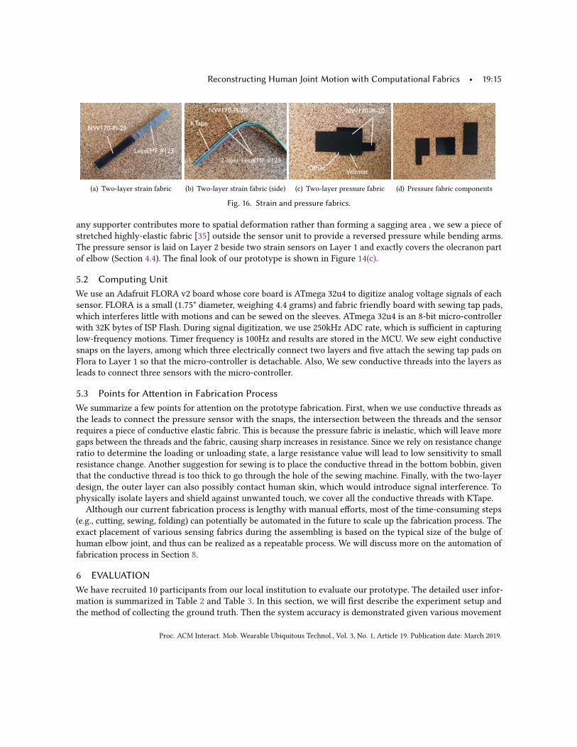
Strain Fabrics. We use LessEMF #A321 [34] as the stretchable conductive fabric, which is silver plated with76% Nylon and 24% elastic fiber fabric. Our experiments show that a single-layer strain fabric does not offermechanical stability after repeated stretches, leading to large fluctuating peaks of resistance change ratios overtime (Figure 15(a)). To address this issue, we design a two-layer structure, where we paste a layer of insulativeelastic tape (KTape [11]) atop the LessEMF fabric, fold it with KTape in the middle and LessEMF on the top andbottom, and then sew these layers with elastic zigzag stitches. The strain sensing fabric is cascaded with aninelastic conductive fabric (EeonTex NM170-PI-20 [70]) serving as the reference resistance. The reference fabrichas a similar two-layer structure and layers are sewed using simple inelastic stitches(Figure 16(a) and 16(b) ).We do not choose an electrical resistor (e.g., mm-scale SMD resistor) as the reference resistance mainly becauseconnecting a small SMD resistor to the sensing fabric requires soldering the PIN of the resistor to conductivethreads. Our experiments show that such soldering introduces much higher noise than that of connecting fabricsvia conductive threads. However, we do not rule out SMD resistors as an option and are interested in exploring itin the future.Figure 15(b) illustrates the fabrication process. Such a two-layer structure improves the stability of output
voltage (Figure 15(c)). Specifically, strain fabrics (LessEMF) are cut into pieces of 15 cm × 3 cm in size, resultingin a 1.5cm width sensing fabric after the folding. It is then connected to a 7 cm × 1.5 cm static conductive fabric(EeonTex NM170-PI-20) as the reference resistance. We sew two strain sensors onto Layer 1 using zigzag stitches,which do not influence the elasticity of sensors. They are the main sensing fabrics in our prototype and are placedroughly in accordance with the flat surface of the elbow.
Pressure Fabrics. As we mentioned before, we use 2-layer velostat sandwich structure for our fabric pressuresensor(Figure 16(c)). We place a 3 cm × 4 cm piece of static conductive fabric at the bottom, another 3 cm× 7 cm one on the top and two 3cm×4cm pieces of 1mm-thick pressure-sensitive conductive sheet [72] inbetween(Figure 16(d)). Both the top and bottom layers perform as reference resistors and have an extra partas pins to connect with conductive threads. We use iron-on adhesive hem to stick them together and coverthe sensor with kinesiology tape to fasten and insulate. As pressure that elbow exerts on the sensor without
Proc. ACM Interact. Mob. Wearable Ubiquitous Technol., Vol. 3, No. 1, Article 19. Publication date: March 2019.
Reconstructing Human Joint Motion with Computational Fabrics • 19:15
(a) Two-layer strain fabric (b) Two-layer strain fabric (side) (c) Two-layer pressure fabric (d) Pressure fabric components
Fig. 16. Strain and pressure fabrics.
any supporter contributes more to spatial deformation rather than forming a sagging area , we sew a piece ofstretched highly-elastic fabric [35] outside the sensor unit to provide a reversed pressure while bending arms.The pressure sensor is laid on Layer 2 beside two strain sensors on Layer 1 and exactly covers the olecranon partof elbow (Section 4.4). The final look of our prototype is shown in Figure 14(c).
5.2 Computing UnitWe use an Adafruit FLORA v2 board whose core board is ATmega 32u4 to digitize analog voltage signals of eachsensor. FLORA is a small (1.75" diameter, weighing 4.4 grams) and fabric friendly board with sewing tap pads,which interferes little with motions and can be sewed on the sleeves. ATmega 32u4 is an 8-bit micro-controllerwith 32K bytes of ISP Flash. During signal digitization, we use 250kHz ADC rate, which is sufficient in capturinglow-frequency motions. Timer frequency is 100Hz and results are stored in the MCU. We sew eight conductivesnaps on the layers, among which three electrically connect two layers and five attach the sewing tap pads onFlora to Layer 1 so that the micro-controller is detachable. Also, We sew conductive threads into the layers asleads to connect three sensors with the micro-controller.
5.3 Points for Attention in Fabrication ProcessWe summarize a few points for attention on the prototype fabrication. First, when we use conductive threads asthe leads to connect the pressure sensor with the snaps, the intersection between the threads and the sensorrequires a piece of conductive elastic fabric. This is because the pressure fabric is inelastic, which will leave moregaps between the threads and the fabric, causing sharp increases in resistance. Since we rely on resistance changeratio to determine the loading or unloading state, a large resistance value will lead to low sensitivity to smallresistance change. Another suggestion for sewing is to place the conductive thread in the bottom bobbin, giventhat the conductive thread is too thick to go through the hole of the sewing machine. Finally, with the two-layerdesign, the outer layer can also possibly contact human skin, which would introduce signal interference. Tophysically isolate layers and shield against unwanted touch, we cover all the conductive threads with KTape.Although our current fabrication process is lengthy with manual efforts, most of the time-consuming steps
(e.g., cutting, sewing, folding) can potentially be automated in the future to scale up the fabrication process. Theexact placement of various sensing fabrics during the assembling is based on the typical size of the bulge ofhuman elbow joint, and thus can be realized as a repeatable process. We will discuss more on the automation offabrication process in Section 8.
6 EVALUATIONWe have recruited 10 participants from our local institution to evaluate our prototype. The detailed user infor-mation is summarized in Table 2 and Table 3. In this section, we will first describe the experiment setup andthe method of collecting the ground truth. Then the system accuracy is demonstrated given various movement
Proc. ACM Interact. Mob. Wearable Ubiquitous Technol., Vol. 3, No. 1, Article 19. Publication date: March 2019.

19:16 • R. Liu et al.
Table 2. Information of ten participants in the evaluation.Gender Height/cm Weight/kg
Male Female <170 170 - 180 >180 <60 60 - 80 >80# of Users 7 3 2 4 4 3 4 3
Table 3. The upper and lower arm size of each participant.User ID 1 2 3 4 5 6 7 8 9 10
Upper Arm Size (cm) 31 29.5 30 32 27.5 23 24.5 22.5 23 23Lower Arm Size (cm) 27 22.5 23.5 24 24.5 21.5 25 23 20.5 22
patterns. We further examine the reliability of our system regarding the sensor movement and washability. Finally,we will examine the comfort level of the prototype via a user study.
Setup. Each participant is instructed to wear the prototype with the size that fits his/her arm. With two availablesizes of the prototype (Section 5), participants whose upper arms are with perimeters larger than 24 cm wear thelarger size. Various types of motion patterns are designed and demonstrated in videos. After watching the video,participants imitate the motion, while the prototype records fabric sensing data, which are then transmitted toa laptop running the joint angle inference algorithm. In the end of the experiment, each participant fills in aquestionnaire to rate the level of tightness, comfort and flexibility of wearing the fabric prototype, as well as theirfeedback on the one-time calibration. Additional feedback is also solicited on the comparison of our prototypeand commercial compression sleeves.
To collect ground truth data, we choose the Vicon system [9] because of its higher accuracy in comparison toother motion-capture systems such as Kinect. Its sensing ability relies on the reflective skin markers and infraredcameras and the system error is less than 2 mm [51]. We attach optical markers to each participant’s elbow tomeasure the skin deformation and elbow angle. Our early tests reveal that with only three markers attached tothe arm (on upper arm, elbow joint and lower arm respectively), Vicon occasionally loses track of the markersas these small markers can be easily occluded. To address this problem, we create two rigid planes with hardpaper board and place them onto the upper and lower arm skin surface. These planes reduce occlusions and helpVicon track the arms and output the joint angle even if one or two points on the plane are missing. Meanwhile,to synchronize and compare data from Vicon and our system in real time, we develop a cross-platform toolprogrammed in C to gather data from MCU and Vicon system together. We integrate the calibration procedureinto the tool. The experiment with each participant takes roughly 40 minutes, where calibration and adjustmenttakes only three minutes.
6.1 Accuracy of Inferring Joint AnglesWe start by examining the accuracy of sensing joint angles using our fabric prototypes. Specifically, the followingsequence of motions is designed for each participant:(1) Flex the elbow by various degrees (i.e., 45◦, 90◦, and 150◦), and repeat the motion at three levels of speed.
Repeat each motion three times and then rest 30 seconds in the end.(2) Repeat the above motion sequence at the same three levels of speed but pause 5 seconds at 45◦, 90◦, and
150◦. Rest 30 seconds after this step.(3) Perform free-form motions, including waving tennis racket, performing the yoga tree pose and belly button
challenge.The first two steps are controlled motions for evaluating the efficacy of various design elements to handle
different movement angles and speed. Specifically, by adding the 5-second pause, step (2) is meant to examine theefficacy of the design element on stress relaxation and drift compensation (Section 4.3). The third step evaluatesthe system under free-form motions.
Proc. ACM Interact. Mob. Wearable Ubiquitous Technol., Vol. 3, No. 1, Article 19. Publication date: March 2019.

Reconstructing Human Joint Motion with Computational Fabrics • 19:17
0
5
10
15
20
1 2 3 4 5 6 7 8 9 10
Err
or
(degre
e)
Participant ID
(a)
0
5
10
15
Small Medium Large
Err
or
(degre
e)
Participant arm size
(b)
0
5
10
15
20
Male Female
Err
or
(degre
e)
(c)
Fig. 17. Overall accuracy in inferring joint angles, including the average accuracy of each participant (a), the impact of armsize on angular errors (b), and the overall accuracy for each gender (c).
We next discuss our results, starting from overall accuracy and then diving into the analysis on controlled andfree-form motions. We evaluate accuracy by calculating absolute joint angular errors, i.e., the absolute differencesbetween inferred and ground-truth joint angles.
6.1.1 Overall Accuracy. We evaluate system’s overall accuracy by aggregating joint angular errors of all par-ticipants in performing all steps of the motion sequence. Figure 17(a) plots the average angular error for eachparticipant, where error bars represent the range between the 5-th and 95-th percentiles. Overall, the medianaccuracy across users is 9.69◦, which can facilitate rehabilitation applications [85] that aim to limit the rangefor patient’s joint movement (e.g., from 30◦-100◦). Comparing results across participants, we observe that theaverage angular error with participant 8 is the lowest. This is because the arm size of this participant is used asthe reference for building the fabric prototype worn by this participant. The prototype best fits this participant.We further analyze the impact of participant’s arm size on joint angular error. We divide participants into
three groups based on the perimeters of their upper arms: small (upper arm perimeter < 24 cm), medium (24cm ≤ upper arm perimeter ≤ 28 cm), and large (upper arm perimeter > 28 cm). We focus on the size of theupper arm because lower arm size has almost no impact on wearing tightness. We aggregate joint angular errorsof participants in each group, and plot the average as well as the 5-th and 95-th percentiles for each group inFigure 17(b). We observe that for participants with medium arm size, their average joint angular error is thelowest. This is because the prototypes best fit these participants without being too loose or tight. Too tight contactbetween skin and fabric sensor limits the spatial deformation of velostat material, which causes errors in motionstate determination. On the other hand, when the prototype is too loose, the fabric fails to capture minor skindeformation, which also leads to larger errors.We also examine the overall accuracy for male and female participants. Figure 17(c) plots the average with
error bars covering the 5-th and 95-th percentiles. We do not observe differences with statistical significance.This is expected as their arms have the same anatomic structure.
6.1.2 Controlled Motion. We now zoom in on results of controlled motions (step (1) and (2)), aiming to examinethe impact of pause, motion speed, and flexion angle on the accuracy of sensing joint angles.
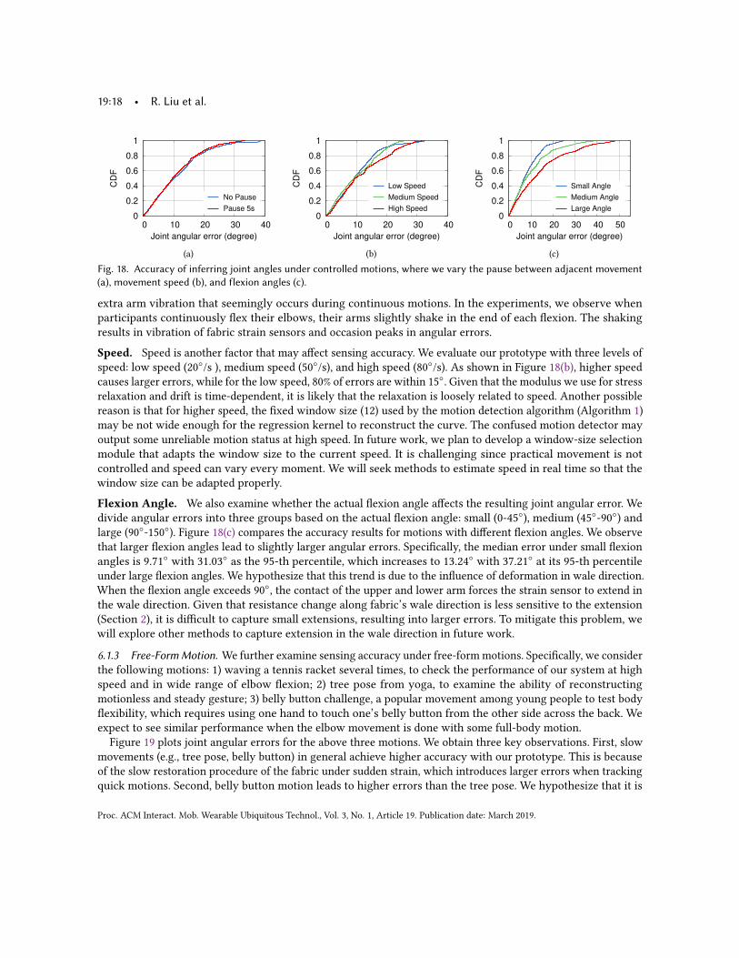
Pause. To analyze the impact of pause at different stress levels, we aggregate the angular errors in step (1), wherethere is no pause between joint movement. We compare them to that in step (2), where 5-second pause is added.Figure 18(a) compares the CDFs. We observe negligible differences between the distributions. It indicates that thesystem can track continuous joint motion while controlling the error accumulation, thanks to the design elementon stress relaxation and drift compensation (Section 4.3) that deals with the drift error. However, the distributionof errors during continuous motion has a slightly longer tail, with the maximal error of 38.7◦, compared to themaximal error of 34.3◦ during motions with 5-second pause. We hypothesize that the longer tail is due to the
Proc. ACM Interact. Mob. Wearable Ubiquitous Technol., Vol. 3, No. 1, Article 19. Publication date: March 2019.
19:18 • R. Liu et al.
0
0.2
0.4
0.6
0.8
1
0 10 20 30 40
CD
F
Joint angular error (degree)
No Pause
Pause 5s
(a)
0
0.2
0.4
0.6
0.8
1
0 10 20 30 40
CD
F
Joint angular error (degree)
Low Speed
Medium Speed
High Speed
(b)
0
0.2
0.4
0.6
0.8
1
0 10 20 30 40 50
CD
F
Joint angular error (degree)
Small Angle
Medium Angle
Large Angle
(c)Fig. 18. Accuracy of inferring joint angles under controlled motions, where we vary the pause between adjacent movement(a), movement speed (b), and flexion angles (c).
extra arm vibration that seemingly occurs during continuous motions. In the experiments, we observe whenparticipants continuously flex their elbows, their arms slightly shake in the end of each flexion. The shakingresults in vibration of fabric strain sensors and occasion peaks in angular errors.
Speed. Speed is another factor that may affect sensing accuracy. We evaluate our prototype with three levels ofspeed: low speed (20◦/s ), medium speed (50◦/s), and high speed (80◦/s). As shown in Figure 18(b), higher speedcauses larger errors, while for the low speed, 80% of errors are within 15◦. Given that the modulus we use for stressrelaxation and drift is time-dependent, it is likely that the relaxation is loosely related to speed. Another possiblereason is that for higher speed, the fixed window size (12) used by the motion detection algorithm (Algorithm 1)may be not wide enough for the regression kernel to reconstruct the curve. The confused motion detector mayoutput some unreliable motion status at high speed. In future work, we plan to develop a window-size selectionmodule that adapts the window size to the current speed. It is challenging since practical movement is notcontrolled and speed can vary every moment. We will seek methods to estimate speed in real time so that thewindow size can be adapted properly.
Flexion Angle. We also examine whether the actual flexion angle affects the resulting joint angular error. Wedivide angular errors into three groups based on the actual flexion angle: small (0-45◦), medium (45◦-90◦) andlarge (90◦-150◦). Figure 18(c) compares the accuracy results for motions with different flexion angles. We observethat larger flexion angles lead to slightly larger angular errors. Specifically, the median error under small flexionangles is 9.71◦ with 31.03◦ as the 95-th percentile, which increases to 13.24◦ with 37.21◦ at its 95-th percentileunder large flexion angles. We hypothesize that this trend is due to the influence of deformation in wale direction.When the flexion angle exceeds 90◦, the contact of the upper and lower arm forces the strain sensor to extend inthe wale direction. Given that resistance change along fabric’s wale direction is less sensitive to the extension(Section 2), it is difficult to capture small extensions, resulting into larger errors. To mitigate this problem, wewill explore other methods to capture extension in the wale direction in future work.
6.1.3 Free-FormMotion. We further examine sensing accuracy under free-formmotions. Specifically, we considerthe following motions: 1) waving a tennis racket several times, to check the performance of our system at highspeed and in wide range of elbow flexion; 2) tree pose from yoga, to examine the ability of reconstructingmotionless and steady gesture; 3) belly button challenge, a popular movement among young people to test bodyflexibility, which requires using one hand to touch one’s belly button from the other side across the back. Weexpect to see similar performance when the elbow movement is done with some full-body motion.
Figure 19 plots joint angular errors for the above three motions. We obtain three key observations. First, slowmovements (e.g., tree pose, belly button) in general achieve higher accuracy with our prototype. This is becauseof the slow restoration procedure of the fabric under sudden strain, which introduces larger errors when trackingquick motions. Second, belly button motion leads to higher errors than the tree pose. We hypothesize that it is
Proc. ACM Interact. Mob. Wearable Ubiquitous Technol., Vol. 3, No. 1, Article 19. Publication date: March 2019.

Reconstructing Human Joint Motion with Computational Fabrics • 19:19
0
0.2
0.4
0.6
0.8
1
0 10 20 30 40 50 60 70 80 90
CD
F
Joint angular error (degree)
Yoga tree pose
Belly button
Racket waving
Fig. 19. Accuracy of inferring joint anglesunder three free-form motions.
0
0.2
0.4
0.6
0.8
1
0 10 20 30 40 50 60
CD
F
Joint angular error (degree)
Left offset
Right offset
No offset
Fig. 20. Impact of fabric displacement onsensing accuracy.
0
0.2
0.4
0.6
0.8
1
0 10 20 30 40 50 60 70 80 90
CD
F
Joint angular error (degree)
Before washHand wash
Machine wash
Fig. 21. Impact of wash on fabric’s sens-ing performance.
due to the rotation of lower arm and wrist during this motion. Since the prototype is currently designed to trackmainly elbow flexion, joint rotation in other degrees of freedom introduces extra deformation and pressure andcan interfere with the sensing of joint angle. Finally, similarly to our prior results on speed and flexion angle,motions (racket waving) with larger flexion angles and higher speeds lead to higher errors. During these motions,we observe more wrinkles accumulated around the fabric of the elbow region. Wrinkles affect fabric resistanceand cause larger errors in inferring joint angles. In Section 8, we will discuss our future work to better deal withwrinkles.
6.2 Sensing RobustnessAfter examining the sensing accuracy, we now move on to evaluating the sensing robustness of our fabricprototypes. We focus on two practical factors that can affect fabric’s sensing performance: 1) the displacement ofsensing fabric around the joint region, which can be caused either by initial wearing or by later motions; and 2)repeated wash of the fabric prototype after the MCU is detached.
Fabric Displacement. The prototype performs the best when the sensing fabrics are placed in the right regionof the elbow: the two strain fabrics are right around the ulna bone while the pressure fabric is right aroundthe radius bone (Figure 13). In practice, however, these sensing fabrics can slightly shift away from their bestsensing spots, either because of continuous joint motion or the improper alignment during the initial wearing.To evaluate the impact of fabric displacement, we instruct one participant to wear the prototype and flex theelbow by various angles (45◦, 90◦, and 150◦) with a speed of 20◦/s. We emulate fabric displacement by slightlymoving the sensing fabrics from their optimal sensing spots by 1 cm, either to the left or to the right. We thencompare the results to that without any offset to examine the impact of fabric displacement on sensing accuracy.Figure 20 plots the CDFs of angular errors with and without fabric displacement. As expected, offsets from
the center/optimal position slightly increase the joint angular error. The main reason is that these small offsetscause one of the strain fabrics to move beyond the olecranon, which breaks the parallelism of the two fabrics.This introduces error in calculating the angle from the differential inputs. Displacement with the right-side offsetleads to slightly smaller errors because the pressure fabric is on the left of the strain fabrics. As a result, movingto the right has less influence on the pressure fabric. Note that in practice, larger displacement can be easilynoticed and corrected by simply placing the fabrics to the center of the elbow. Overall, the results reveal thatsmall offsets (≤1 cm) introduce a minor increase in joint angular errors, demonstrating the efficacy of the dualinput sensing (Section 4.4) in dealing with motion artifact.
Washability. Washability is essential to long-term uses of the fabric prototype. The only electrical componentof our prototype is MCU, which can be easily detached through a button (Section 5.2), leaving the rest of theprototype washable. To examine the impact of wash on the fabric’s sensing ability, we test two types of washing:
Proc. ACM Interact. Mob. Wearable Ubiquitous Technol., Vol. 3, No. 1, Article 19. Publication date: March 2019.
19:20 • R. Liu et al.
machine wash and hand hash, where the latter is more gentle. We instruct a participant to wear the prototypebefore and after washing to perform all steps of motion sequence and compare the errors in inferring joint angles.Figure 21 compares the CDFs of joint angular errors before and after wash. We observe that both types of
wash degrade fabric’s sensing performance. This is partially because fabrics shrink to some extent after wash,even if we dry the prototype thoroughly in open air. In comparison, machine wash affects the performance moreseverely, resulting into a median angular error of 34.1◦ and a maximum error of 72.4◦. This is mainly becauseafter machine wash, some conductive threads are broken while others have loose contact with the fabric. Bothgreatly affect the sensing of resistance change ratios. Gentle hand wash, on the other hand, can better protectthe conductive threads and cause minor degradation (7.64◦) to the sensing performance. In future work, we areinterested in further improving the prototype’s robustness against wash through better fabrication. We will alsoconduct longer-term studies to examine the impact of repeated washes (Section 8).
6.3 Comfort LevelTo evaluate the comfort level of our prototypes, we conduct a user study with ten participants to solicit theirinput. All participants of our experiments are asked to fill in a questionnaire. The questionnaire asks participantsto rate with the scale of 1–9 the following attributes of the prototype system: (1) tightness (1-too tight, painful towear; 9-very loose, do not feel wearing it at all), (2) flexibility (1-too rigid, cannot perform any motion; 9-veryflexible, no hindrance to performing any activities), (3) one-time calibration in the beginning (1-too long, tedious;9-quick, not an overhead at all), and (4) the overall comfort level of wearing our prototype (1-very uncomfortable;9-very comfortable, do not mind wearing it at all times).We calculate the average ratings of the above four attributes, and they are 6.1, 8.5, 8.3 and 8.8 respectively. It
demonstrates that our prototype achieves an acceptable comfort level: the sizes of our prototype well adapt totarget users with different figures; the prototype does not hinder motions for sports and everyday use; one-timecalibration after purchasing it is relatively quick and acceptable. Additionally, 9 participants think applying oursystem into the teaching process of certain sports like yoga or gymnastics would be very helpful (8 points ormore) to their progress. All the participants are willing to purchase such a system for $30-$40.Additionally, we have also solicited participant feedback comparing the comfort level of our prototype with
other commercial sleeves. We invite participants to wear off-the-shelf compression sleeves [1, 2] for 30 minutes,which roughly the same duration of wearing our fabric prototype during the experiment. Overall, participantshave not mentioned any issues related to wear comfort using our prototype. A participant (P5) comments that"There is no difference between wearing your prototype and the compression sleeves.". Another participant (P2)comments that " When you are playing sports, this would not have any influence just as the protection armsleeves, while it tightness might make you feel a little bit uncomfortable when you are typing before a computer.".
7 RELATED WORKWe divide existing works on fabric sensing into two main categories based on their sensing capabilities.
Motion Classification. The first category of works focus on differentiating a pre-defined set of motions oractivities. In particular, two types of resistive fabric strain sensors have been explored in the past.
The first type is made of textile structure with conductive yarns. The embedded conductive yarns form manyconductive paths, where contact resistance would change following the given mechanical stretch. Atalay etal. [12] chose to use silver yarn and nylon as the material and produced a weft-knitted strain sensor. Zhang etal. [89] created knitted strain sensors by using stainless steel and carbon yearns. The advantage of this kind ofstrain sensor is that the integration of the conductive medium into the textile structure is easily accomplishedby slightly modifying existing knitting machine procedure. However, the mixture or the filling material of thesensing yarn is always rigid, which may cause discomfort while wearing it.
Proc. ACM Interact. Mob. Wearable Ubiquitous Technol., Vol. 3, No. 1, Article 19. Publication date: March 2019.
Reconstructing Human Joint Motion with Computational Fabrics • 19:21The other type is to coat elastic material (e.g., lycra) by intrinsically conductive polymer (ICP). In 1997, Lorussi
et al. [46] developed a PPy-coated Lycra fabric and presented a wearable system able to reveal the status of bodykinematic chains. Oh et al. [57] coated PPy on Nylon-spandex(95:5) and obtained a strain sensor which can keepsensing until 60% extension. Irmandy et al. [82] used off-the-shelf PPy-coated fabric LTT-SLPA(28% Elastane, 72%Nylon) made by EEONYX Inc. to develop a deformable musical keyboard. They suggested that the maximumstrain the sensor could handle is around 100-150%, which indicates this fabric is ideal for wearable strain sensoras its working space is large enough for skin surface deformation happening on our body.We are inspired by these prior works on fabric sensing. Our work differs in that our system achieves much
higher sensing granularity by enabling the inference of actual joint angles, rather than differentiating pre-definedgestures or poses.
Motion Reconstruction. The second category of works aim to compute joint angles. Most of these works relyon specially-designed materials. As examples, Mattmann et al. [49] used a novel thermoplastic elastomer strainsensor and attached it to the back of a tight-fitting cloth to recognize upper body postures. Menguc et al. [50] pourliquid silicone on a 3D print mold and inject EGaIn to generate a soft strain sensor. Bae et al. [13] chose graphene,a special carbon structure as its base, made a transparent strain sensor detecting the motion of a finger. Ali etal. [37] designed functionalized fabric to measure triboelectric charges induced by fabric deformation, making itpossible to differentiate joint movement types (extension, flexion) and movement speed with the loose-fittingcloth. All these strain sensors require complicated chemical procedure and special techniques, which entail ahigher manufacturing cost. Our work differs in that we examine the use of off-the-shelf, low-cost fabrics forfine-grained joint motion sensing.Additionally, fiber has also been explored for joint motion sensing. Peter et al. [27] incorporated conductive
fibers into the fabric with elastic cord and sensed the joint angle according to the resistance change of conductivefibers. Massimiliano et al. [24] made use of optical fiber, which measures the relative angle in a rotating jointbased on the intensity modulation of a laser beam propagating in a single-mode optical fiber. Sunghoon et al. [43]developed a sensing system comprising a retractable reel, a string and a potentiometer. This system estimates thejoint angle accurately under fast movement settings with the help of the retractable reel. Our work differs in thatwe study a different approach using off-the-shelf, low-cost fabrics, which potentially can be more flexible, andmore comfortable to wear compared to fibers and reels.Other motion-reconstruction systems involving fabric sensing combine fabric sensors with other types of
sensors. Examples include E-Skin by Xenon [10], on-body sensing system by FIGUR8 [5] and super soft stretchsensor by stretch sense [7]. Besides sensing fabric, E-Skin system places 3-axis accelerometers and 3-axis gyrosensors on the plastic part on the chest [3]. Stretch sensor attaches an extra circuit unit at the end of its smartgarments [8]. Adrian [23] used the wearable inertial measurement units (IMUs) to estimate the "movement skill".FIGUR8 claims to use 9-axis inertial measuring unit [4] in its products. Our work differs in that we reconstructjoint motion solely based on fabric sensing without the aid from other types of sensors.
8 CONCLUSION AND FUTURE WORKIn this work, we studied the use of off-the-shelf conductive fabrics to sense the strain and pressure during jointmotion and infer joint rotational angle. To achieve accurate and robust sensing, challenges arising from theinherent properties of fabric materials are addressed. Our work leveraged models from material science andbiomechanics to characterize fabric properties and the relationship between skin deformation and joint angle. Wefabricated prototypes with off-the-shelf fabrics and a micro-controller. The system’s sensing accuracy, robustness,and comfort are demonstrated by conducting system experiments and user studies with 10 participants.We recognize the limitations of our current study and summarize our ongoing and future work as follows:
Proc. ACM Interact. Mob. Wearable Ubiquitous Technol., Vol. 3, No. 1, Article 19. Publication date: March 2019.

19:22 • R. Liu et al.
• We currently fabricated prototypes only for the elbow joint. Moving forward, we plan to fabricate prototypesfor other types of body joints and examine the efficacy of our design. The general design principle still appliesand we will need to consider the anatomy of other joint types for possible adjustments on inferring joint angle.For joints such as wrists with larger degrees of freedom during rotation and capable of performing more typesof rotational movement, we will consider optimizing the current design and arrangement of sensing fabrics tomaximize the number of rotation types the system is capable of tracking.• Since our sensing fabrics are conductive, sweat can affect their conductivity and interfere with fabric sensing.We have not noticed any participant sweating during the experiment, thus the impact of sweat on the sensingperformance is still unknown. In the future, we will test our prototypes with users performing vigorousexercises to examine the system performance under excessive sweating. We will explore thinner fabrics tohelp the body better dissipate heat. Also, we will consider arranging insulative layers close to skin to protectsensing fabrics and the few conductive threads connecting to the micro-controller from sweat.• From experiments we noticed that when the sensing fabric is not well fitting the joint surface, joint motionoccasionally wrinkles the fabric, which affects fabric resistance and causes larger errors in inferring jointangles. This issue is partially due to limited (two) size options of current prototypes, which do not fit well forsome participants. We plan to fabricate prototypes in more sizes to ensure exact tightness and reduce wrinkles.We will also consider designing prototypes with adjustable sizes using the nylon fastener tape. Additionally,we will explore fabrics with better elasticity so that they can retract/stretch more quickly to better fit jointsurface during fast motion.• The current fabrication of the fabric prototype involves lengthy human efforts. We are interested in examiningpossible automation of certain steps to expedite the fabrication process. Most fabrication efforts have been oncutting, folding, and sewing the fabrics, which potentially can be automated by machines for mass production.The assembling of various fabric pieces needs only knowledge on the typical size of the bulge of the jointto ensure that sensing fabrics are properly placed to sense skin deformation and pressure. Since the fabricprototype will be fabricated in a small number of size options, for users fitting in the same size, their individualdifferences in the size of joint bulge would be small and can be handled by the dual sensing design (Section 4.4)to ensure sensing robustness. Thus, the fabric assembling does not need to be conducted on a per-user basisand can potentially be made repeatable.• We recognize the limitations of our current user study, which is based on a small user population and short-termwearing experiences. We plan to fabricate more prototypes, expand our user base, and solicit feedback aftermore diverse activities. We will also conduct longer-term studies to examine the durability of the system(especially after repeated washes) and user experience on fabric’s overall comfort, flexibility, tightness afterlong-time wear. We are reaching out to orthopedists at a local hospital to discuss possible deployment of ourprototypes for monitoring joint recovery after surgeries.
ACKNOWLEDGMENTSWe sincerely thank reviewers for their insightful comments and suggestions that helped improve the paper. Thiswork is in part supported by the Neukom CompX Faculty Grant at Dartmouth College, and National ScienceFoundation under IIS-1822819. Any opinions, findings, and conclusions or recommendations expressed in thismaterial are those of the authors and do not necessarily reflect those of the funding agencies or others.
REFERENCES[1] 2018. Compression Arm Sleeve. https://www.amazon.com/d/Elbow-Braces/Kunto-Fitness-Compression-Tendonitis-Treatment/
B010P9Q13K/ref=sr_1_1_sspa?s=sporting-goods&ie=UTF8&qid=1542318962&sr=1-1-spons&keywords=Compression+Arm+Sleeve&psc=1
Proc. ACM Interact. Mob. Wearable Ubiquitous Technol., Vol. 3, No. 1, Article 19. Publication date: March 2019.

Reconstructing Human Joint Motion with Computational Fabrics • 19:23
[2] 2018. Compression Sleeve. https://www.amazon.com/McDavid-Compression-Protection-Basketball-Baseball/dp/B016WZG6KO?ref_=Oct_BSellerC_9590773011_4&pf_rd_p=329f6528-119f-5272-a932-88cab21c7435&pf_rd_s=merchandised-search-6&pf_rd_t=101&pf_rd_i=9590773011&pf_rd_m=ATVPDKIKX0DER&pf_rd_r=39BDF952GDARHYTKSK6H&pf_rd_r=39BDF952GDARHYTKSK6H&pf_rd_p=329f6528-119f-5272-a932-88cab21c7435
[3] 2018. E-Skin Sensor. https://xenoma.com/eskin-dk[4] 2018. Figur 8 Sensors. https://figur8tech.com/pages/research-and-development-kit[5] 2018. Figur8 Tech. https://figur8tech.com/blogs/figur8[6] 2018. Rehabilitation Gui delines for Elbow Ulnar Collateral Ligament (UCL) Reconstruction. https://www.uwhealth.org/files/uwhealth/
docs/sportsmed/SM_UCL_reconstruction.pdf[7] 2018. Stretch Sense. https://www.stretchsense.com/stretch-sensors/[8] 2018. Stretch Sense Circuit. https://www.stretchsense.com/smart-garments/[9] 2018. Vicon. https://www.vicon.com/[10] 2018. Xenoma E-Skin. https://xenoma.com/[11] Amazon. 2018. Kinesiology Tape. https://www.amazon.com/KT-Tape-Kinesiology-Therapeutic-Sports/dp/B003DV9JGO/ref=sr_1_1/
136-0678870-8281028?s=sports-and-fitness&ie=UTF8&qid=1533589584&sr=1-1&refinements=p_4%3AKT+Tape[12] Ozgur Atalay, William Richard Kennon, and Erhan Demirok. 2015. Weft-Knitted Strain Sensor for Monitoring Respiratory Rate and Its
Electro-Mechanical Modeling. IEEE Sensors . . . 15, 1 (2015), 110–122.[13] S H Bae, Y Lee, B K Sharma, H J Lee, J H Kim, and J H Ahn. 2013. Graphene-based transparent strain sensor. Carbon 51 (2013), 236–242.[14] Abdelkareem Bedri, Richard Li, Malcolm Haynes, Raj Prateek Kosaraju, Ishaan Grover, Temiloluwa Prioleau, Min Yan Beh, Mayank Goel,
Thad Starner, and Gregory Abowd. 2017. EarBit: Using Wearable Sensors to Detect Eating Episodes in Unconstrained Environments.Proceedings of the ACM on Interactive, Mobile, Wearable and Ubiquitous Technologies 1, 3 (Sept. 2017), 37–20.
[15] Mary Ellen Berglund, Julia Duvall, and Lucy E Dunne. 2016. A survey of the historical scope and current trends of wearable technologyapplications. ISWC (2016), 40–43.
[16] Ceren Günenç Beşer, Deniz Demiryürek, Hakan Özsoy, Burcu Erçakmak, Mutlu Hayran, Onur Kızılay, and Arzu Özsoy. 2014. Redefiningthe proximal ulna anatomy. Surgical and Radiologic Anatomy 36, 10 (July 2014), 1023–1031.
[17] T Bhattacharjee, A Jain, S Vaish, M D Killpack, and C C Kemp. 2013. Tactile sensing over articulated joints with stretchable sensors. In2013 World Haptics Conference (WHC 2013). IEEE, 103–108.
[18] Johann Borenstein, Lauro Ojeda, and Surat Kwanmuang. 2009. Heuristic reduction of gyro drift in IMU-based personnel trackingsystems. In SPIE Defense, Security, and Sensing, Craig S Halvorson, Šárka O Southern, B V K Vijaya Kumar, Salil Prabhakar, and Arun ARoss (Eds.). SPIE, 73061H.
[19] Toni E Campbell, Bridget J Munro, Gordon G Wallace, and Julie R Steele. 2007. Can fabric sensors monitor breast motion? Journal ofBiomechanics 40, 13 (2007), 3056–3059.
[20] Gerard Canal, Sergio Escalera, and Cecilio Angulo. 2016. A real-time Human-Robot Interaction system based on gestures for assistivescenarios. Computer Vision and Image Understanding 149 (2016), 65 – 77. https://doi.org/10.1016/j.cviu.2016.03.004
[21] Matthieu K Chardon, Yasin Y Dhaher, Nina I Suresh, Giselle Jaramillo, and W Zev Rymer. 2015. Estimation of musculotendon kinematicsunder controlled tendon indentation. Journal of Biomechanics 48, 13 (Oct. 2015), 3568–3576.
[22] Philo Tan Chua, R. Crivella, B. Daly, Ning Hu, R. Schaaf, D. Ventura, T. Camill, J. Hodgins, and R. Pausch. 2003. Training for physicaltasks in virtual environments: Tai Chi. In IEEE Virtual Reality, 2003. Proceedings. 87–94. https://doi.org/10.1109/VR.2003.1191125
[23] A. Derungs, S. Soller, A. Weishäupl, J. Bleuel, G. Berschin, and O. Amft. 2018. Regression-based, mistake-driven movement skill estimationin Nordic Walking using wearable inertial sensors. In 2018 IEEE International Conference on Pervasive Computing and Communications(PerCom). 1–10. https://doi.org/10.1109/PERCOM.2018.8444576
[24] M. Donno, E. Palange, F. Di Nicola, G. Bucci, and F. Ciancetta. 2008. A New Flexible Optical Fiber Goniometer for Dynamic AngularMeasurements: Application to Human Joint Movement Monitoring. IEEE Transactions on Instrumentation and Measurement 57, 8 (Aug2008), 1614–1620. https://doi.org/10.1109/TIM.2008.925336
[25] Tsutomu Fujimura. 2012. Investigation of the relationship betweenwrinkle formation and deformation of the skin using three-dimensionalmotion analysis. Skin Research and Technology 19, 1 (June 2012), e318–e324.
[26] Shin-ichi Fujiwara, Hajime Taru, and Daisuke Suzuki. 2010. Shape of articular surface of crocodilian (Archosauria) elbow joints and itsrelevance to sauropsids. Journal of Morphology 1 (2010), NA–NA.
[27] Peter T. Gibbs and HHarry Asada. 2005. Wearable Conductive Fiber Sensors for Multi-Axis Human Joint Angle Measurements. Journalof NeuroEngineering and Rehabilitation 2, 1 (02 Mar 2005), 7. https://doi.org/10.1186/1743-0003-2-7
[28] Guido Gioberto and Lucy E Dunne. 2012. Garment Positioning and Drift in Garment-Integrated Wearable Sensing. In 2012 16th AnnualInternational Symposium on Wearable Computers (ISWC). IEEE, 64–71.
[29] R. Gnanadesikan. 1977. Methods for statistical data analysis of multivariate observations / R. Gnanadesikan. Wiley New York. x, 311 p. :pages.
Proc. ACM Interact. Mob. Wearable Ubiquitous Technol., Vol. 3, No. 1, Article 19. Publication date: March 2019.

19:24 • R. Liu et al.
[30] Linsey Griffin, Crystal Compton, and Lucy E Dunne. 2016. An analysis of the variability of anatomical body references withinready-to-wear garment sizes. In Proceedings of the 2016 ACM International Symposium on Wearable Computers - ISWC ’16.
[31] H Harms, O Amft, and D Roggen. 2009. Rapid prototyping of smart garments for activity-aware applications. Journal of Ambient . . .(2009).
[32] Ragnar Holm. 1967. Electric Contacts. Springer Berlin Heidelberg, Berlin, Heidelberg.[33] https://academic.csuohio.edu/. 2018. Linear Viscoelasticity. https://academic.csuohio.edu/duffy_s/Linear_Visco.pdf[34] LessEMF Inc. 2018. Stretch Conductive Fabric. Retrieved Aug 4, 2018 from https://www.lessemf.com/321.pdf[35] Joaan. 2018. Superflex Performance Fabric. https://www.joann.com/superflex-compression-performance-fabric-black/15226897.html#
q=performance%2Bfabric&prefn1=prod_type&sz=36&start=37&prefv1=Product[36] Joann.com. 2018. Micro-Flex Knit Fabric. Retrieved Aug 10, 2018 from https://www.joann.com/
loungeletics-performance-micro-flex-compression-knit-fabric-59-heather/15781511.html[37] Ali Kiaghadi, Morgan Baima, Jeremy Gummeson, Trisha Andrew, and Deepak Ganesan. 2018. Fabric as a Sensor: Towards Unobtrusive
Sensing of Human Behavior with Triboelectric Textiles. In Proceedings of the 16th ACM Conference on Embedded Networked SensorSystems, SenSys 2018, Shenzhen, China, November 4-7, 2018. 199–210. https://doi.org/10.1145/3274783.3274845
[38] Laurel Kuxhaus, Sisi Zeng, and Charles J Robinson. 2014. Dependence of elbow joint stiffness measurements on speed, angle, and musclecontraction level. Journal of Biomechanics 47, 5 (March 2014), 1234–1237.
[39] Yordan Kyosev. 2018. Narrow and Smart Textiles. Springer International Publishing, Cham.[40] S Laksanacharoen and SWongsiri. [n. d.]. Design of apparatus to study human elbow joint motion. In IEEE EMBS Asian-Pacific Conference
on Biomedical Engineering, 2003. IEEE, 236–237.[41] Alberto Leardini, Lorenzo Chiari, Ugo Della Croce, and Aurelio Cappozzo. 2005. Human movement analysis using stereophotogrammetry.
Gait & Posture 21, 2 (Feb. 2005), 212–225.[42] Jaehong Lee, Hyukho Kwon, Jungmok Seo, Sera Shin, Ja Hoon Koo, Changhyun Pang, Seungbae Son, Jae Hyung Kim, Yong Hoon Jang,
Dae Eun Kim, and Taeyoon Lee. 2015. Conductive Fiber-Based Ultrasensitive Textile Pressure Sensor for Wearable Electronics. 27, 15(2015), 2433–2439.
[43] S. I. Lee, J. Daneault, L. Weydert, and P. Bonato. 2016. A novel flexible wearable sensor for estimating joint-angles. In 2016 IEEE 13thInternational Conference on Wearable and Implantable Body Sensor Networks (BSN). 377–382. https://doi.org/10.1109/BSN.2016.7516291
[44] G Ligorio, D Zanotto, A M Sabatini, and S K Agrawal. 2017. A novel functional calibration method for real-time elbow joint anglesestimation with magnetic-inertial sensors. Journal of Biomechanics 54 (March 2017), 106–110.
[45] Xiaoyou Lin and Boon-Chong Seet. 2015. A Linear Wide-Range Textile Pressure Sensor Integrally Embedded in Regular Fabric. 15, 10(Aug. 2015), 5384–5385.
[46] F Lorussi, E P Scilingo, A Tesconi, A Tognetti, and D De Rossi. [n. d.]. Wearable sensing garment for posture detection, rehabilitationand tele-medicine. In International Conference on Information Technology - Applications in Biomedicine. IEEE, 287–290.
[47] Roanna Lun and Wenbing Zhao. 2015. A Survey of Applications and Human Motion Recognition with Microsoft Kinect. Interna-tional Journal of Pattern Recognition and Artificial Intelligence 29, 05 (2015), 1555008. https://doi.org/10.1142/S0218001415550083arXiv:https://doi.org/10.1142/S0218001415550083
[48] Robert A. Malinzak, Scott M. Colby, Donald T. Kirkendall, Bing Yu, and William E. Garrett. 2001. A comparison of knee joint motionpatterns between men and women in selected athletic tasks. Clinical Biomechanics 16, 5 (2001), 438 – 445. https://doi.org/10.1016/S0268-0033(01)00019-5
[49] Corinne Mattmann, Oliver Amft, Holger Harms, Gerhard Tröster, and Frank Clemens. 2007. Recognizing Upper Body Postures usingTextile Strain Sensors. ISWC (2007), 1–8.
[50] Y Mengüç and Y L Park. 2013. Soft wearable motion sensing suit for lower limb biomechanics measurements. . . . (ICRA) (2013).[51] Pierre Merriaux, Yohan Dupuis, Rémi Boutteau, Pascal Vasseur, and Xavier Savatier. 2017. A Study of Vicon System Positioning
Performance. Sensors 17, 7 (2017). https://doi.org/10.3390/s17071591[52] Sebastian Münzner, Philip Schmidt, Attila Reiss, Michael Hanselmann, Rainer Stiefelhagen, and Robert Dürichen. 2017. CNN-based
sensor fusion techniques for multimodal human activity recognition. ISWC (2017).[53] W M Murray, S L Delp, TS Buchanan Journal of biomechanics, and 1995. [n. d.]. Variation of muscle moment arms with elbow and
forearm position. jbiomech.com ([n. d.]).[54] A. Nakamura, S. Tabata, T. Ueda, S. Kiyofuji, and Y. Kuno. 2005. Dance training system with active vibro-devices and a mobile image
display. In 2005 IEEE/RSJ International Conference on Intelligent Robots and Systems. 3075–3080. https://doi.org/10.1109/IROS.2005.1545565[55] Michiro Negishi, Mark Abildgaard, Ilan Laufer, Terry Nixon, and Robert Todd Constable. 2008. An EEG (electroencephalogram)
recording system with carbon wire electrodes for simultaneous EEG-fMRI (functional magnetic resonance imaging) recording. Journalof Neuroscience Methods 173, 1 (Aug. 2008), 99–107.
[56] N Obaid, M T Kortschot, M Sain Materials, and 2017. [n. d.]. Understanding the stress relaxation behavior of polymers reinforced withshort elastic fibers. mdpi.com ([n. d.]).
Proc. ACM Interact. Mob. Wearable Ubiquitous Technol., Vol. 3, No. 1, Article 19. Publication date: March 2019.

Reconstructing Human Joint Motion with Computational Fabrics • 19:25
[57] Kyung Wha Oh, Hyun Jin Park, and Seong Hun Kim. 2003. Stretchable conductive fabric for electrotherapy. Journal of Applied PolymerScience 88, 5 (May 2003), 1225–1229.
[58] Patrick Parzer, Adwait Sharma, Anita Vogl, Jürgen Steimle, Alex Olwal, and Michael Haller. 2017. SmartSleeve - Real-time Sensing ofSurface and Deformation Gestures on Flexible, Interactive Textiles, using a Hybrid Gesture Detection Pipeline. UIST (2017), 565–577.
[59] Zhi-Tao Rao, Feng Yuan, Bing Li, and Ning Ma. 2014. Effect of elbow flexion angles on stress distribution of the proximal ulnar andradius bones under a vertical load: measurement using resistance strain gauges. Journal of Orthopaedic Surgery and Research 9, 1 (July2014), 1–7.
[60] Jung-Sim Roh, Yotam Mann, Adrian Freed, and David Wessel. 2011. Robust and Reliable Fabric, Piezoresistive Multitouch SensingSurfaces for Musical Controllers. NIME (2011).
[61] O Röhrle, M Sprenger, and S Schmitt. 2016. A two-muscle, continuum-mechanical forward simulation of the upper limb. Biomechanicsand Modeling in Mechanobiology 16, 3 (Nov. 2016), 743–762.
[62] Stefan Schneegass and Alexandra Voit. 2016. GestureSleeve - using touch sensitive fabrics for gestural input on the forearm forcontrolling smartwatches. ISWC (2016).
[63] M Sergio, N Manaresi, F Campi, R Canegallo, M Tartagni, and R Guerrieri. 2003. A dynamically reconfigurable monolithic cmos pressuresensor for smart fabric. IEEE Journal of Solid-State Circuits 38, 6 (June 2003), 966–975.
[64] Shayan Seyedin, Joselito M Razal, Peter C Innis, Ali Jeiranikhameneh, Stephen Beirne, and Gordon G Wallace. 2015. Knitted StrainSensor Textiles of Highly Conductive All-Polymeric Fibers. ACS Applied Materials & Interfaces 7, 38 (Sept. 2015), 21150–21158.
[65] Tien-Wei Shyr, Jing-Wen Shie, Chang-Han Jiang, and Jung-Jen Li. 2014. A Textile-Based Wearable Sensing Device Designed forMonitoring the Flexion Angle of Elbow and Knee Movements. Sensors 14, 3 (March 2014), 4050–4059.
[66] Hloniphile M Sithole, Sabyasachi Mondal, Precious Sibanda, and Sandile S Motsa. 2017. An unsteady MHD Maxwell nanofluid flow withconvective boundary conditions using spectral local linearization method. Open Physics 15, 1 (Oct. 2017), 637–646.
[67] S Šlajpah, R Kamnik, and MMunih. 2014. Kinematics based sensory fusion for wearable motion assessment in human walking. ComputerMethods and Programs in Biomedicine 116, 2 (Sept. 2014), 131–144.
[68] A. Soga, B. Umino, and M. Hirayama. 2009. Automatic Composition for Contemporary Dance Using 3D Motion Clips: Experiment onDance Training and System Evaluation. In 2009 International Conference on CyberWorlds. 171–176. https://doi.org/10.1109/CW.2009.37
[69] sorbothane.com. 2018. Hinge Joint. http://www.innerbody.com/image_skel07/skel31.html[70] sparkfun. 2018. NW170-PI-20. PDF. https://cdn.sparkfun.com/datasheets/E-Textiles/Materials/NW170-PI-20%20TDS.pdf[71] sparkfun. 2018. NW170-SLPA-2k. PDF. https://cdn.sparkfun.com/datasheets/E-Textiles/Materials/NW170-SLPA-2k%20TDS.pdf[72] sparkfun. 2018. Velostat. PDF. https://cdn.sparkfun.com/datasheets/E-Textiles/Materials/NW170-PI-20%20TDS.pdf[73] Seiichi Takamatsu, Takahiro Yamashita, and Toshihiro Itoh. 2016. Meter-scale large-area capacitive pressure sensors with fabric with
stripe electrodes of conductive polymer-coated fibers. Microsystem Technologies 22, 3 (Feb. 2016), 451–457.[74] Xiaoming Tao. 2005. Wearable eletronics and photonics. Elsevier.[75] Alessandro Tognetti, Federico Lorussi, Nicola Carbonaro, and Danilo de Rossi. 2015. Wearable Goniometer and Accelerometer Sensory
Fusion for Knee Joint Angle Measurement in Daily Life. Sensors 15, 11 (Nov. 2015), 28435–28455.[76] Takanori Uchiyama, Tomoyuki Bessho, and Kenzo Akazawa. 1998. Static torque–angle relation of human elbow joint estimated with
artificial neural network technique. Journal of Biomechanics 31, 6 (1998), 545–554.[77] E J Van Zuylen, A van Velzen, and J J Denier van der Gon. 1988. A biomechanical model for flexion torques of human arm muscles as a
function of elbow angle. Journal of Biomechanics 21, 3 (Jan. 1988), 183–190.[78] Anita Vogl, Patrick Parzer, Teo Babic, Joanne Leong, Alex Olwal, and Michael Haller. 2017. StretchEBand - Enabling Fabric-based
Interactions through Rapid Fabrication of Textile Stretch Sensors. CHI (2017).[79] Sylvie Charlotte Frieda Anneliese von Werder and Catherine Disselhorst-Klug. 2016. The role of biceps brachii and brachioradialis for
the control of elbow flexion and extension movements. Journal of Electromyography and Kinesiology 28, C (June 2016), 67–75.[80] Junpu Wang, Pu Xue, Xiaoming Tao, and Tongxi Yu. 2013. Strain Sensing Behavior and Its Mechanisms of Electrically Conductive
PPy-Coated Fabric. Advanced Engineering Materials 16, 5 (2013), 565–570.[81] Zehong Wang, Wei Wang, and Dan Yu. 2017. Pressure responsive PET fabrics via constructing conductive wrinkles at room temperature.
Chemical Engineering Journal 330 (Dec. 2017), 146–156.[82] I Wicaksono. 2016. Design and Implementation of Multi-sensory Fabric as Deformable Musical Interface. (2016).[83] Wikipedia. 2018. Gaussian Kernel Smoother. https://en.wikipedia.org/wiki/Kernel_smoother[84] Wikipedia. 2018. Standard Linear Solid Model. https://en.wikipedia.org/wiki/Standard_linear_solid_model#Kelvin_representation[85] Kevin E. Wilk, Michael M. Reinold, and James R. Andrews. 2004. Rehabilitation of the thrower’s elbow. Clinics in Sports Medicine 23, 4
(2019/01/27 2004), 765–801. https://doi.org/10.1016/j.csm.2004.06.006[86] M. B. Wilk and R. Gnanadesikan. 1968. Probability Plotting Methods for the Analysis of Data. Biometrika 55, 1 (1968), 1–17. http:
//www.jstor.org/stable/2334448[87] www.nurbsfactor.com. 2018. Vicon Camera. http://www.nurbsfactor.com/hardware_vicon.php
Proc. ACM Interact. Mob. Wearable Ubiquitous Technol., Vol. 3, No. 1, Article 19. Publication date: March 2019.

19:26 • R. Liu et al.
[88] A Yao and M Soleimani. 2012. A pressure mapping imaging device based on electrical impedance tomography of conductive fabrics. 32,4 (Sept. 2012), 310–317.
[89] Hui Zhang, Xiaoming Tao, ShanyuanWang, and Tongxi Yu. 2016. Electro-Mechanical Properties of Knitted Fabric Made From ConductiveMulti-Filament Yarn Under Unidirectional Extension. Textile Research Journal 75, 8 (July 2016), 598–606.
[90] Wu Zhou, Peng Peng, Huijun Yu, Bei Peng, and Xiaoping He. 2017. Material Viscoelasticity-Induced Drift of Micro-Accelerometers.Materials 10, 9 (2017), 1077.
[91] R Zhu and Z Zhou. 2004. A Real-Time Articulated Human Motion Tracking Using Tri-Axis Inertial/Magnetic Sensors Package. IEEETransactions on Neural Systems and Rehabilitation Engineering 12, 2 (June 2004), 295–302.
[92] Matthias A Zumstein, Alexander Bürki, Anne-Sophie Massy, Philippe Zysset, and Beat K Moor. 2015. Extra-articular step osteotomy ofthe olecranon: A biomechanical assessment. Clinical Biomechanics 30, 10 (Dec. 2015), 1043–1048.
Received August 2018; revised December 2018; accepted January 2019
Proc. ACM Interact. Mob. Wearable Ubiquitous Technol., Vol. 3, No. 1, Article 19. Publication date: March 2019.