record plus ed04 - ipd industrial products product attachments... · of one amp rating into a...
TRANSCRIPT
Record Plus
C.23
Ve
rsion
s
Intro
A
B
C
D
E
F
G
X
Versions
Plug-in
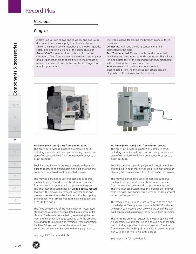
Fixed part
A monoblock base that can be mounted to a backplate
or on profiles and offers IPXXB protection for front access
(FD - IP20, FE and FG - IP40).
It is designed to have exactly the same connection
profile as the breaker it goes with, thus allowing the
installation of all terminal shields and terminals that the
standard breaker offers. These include rear and angular
connectors, spreaders, customized ring terminal
connectors and extenders.
The base is connected by re-ultilising the nut inserts
and connection bolts supplied with the breaker.
Spares
Kits are available containing a number of trip interlock
mechanisms, breaker nut inserts and connection bolts.
The kits can be used in cases where the bases must be con-
nected and where breakers have not (yet) been supplied.
Accessories
Several optional accessories are available. To allow the
use of internal accessories in a plug-in configuration the
wiring can be connected through plug and socket com-
binations. To prevent the incorrect insertion of a breaker
of one amp rating into a socket pre wired for an other
amp rating interchange prevention kits are available.
Please refer to page C.27.
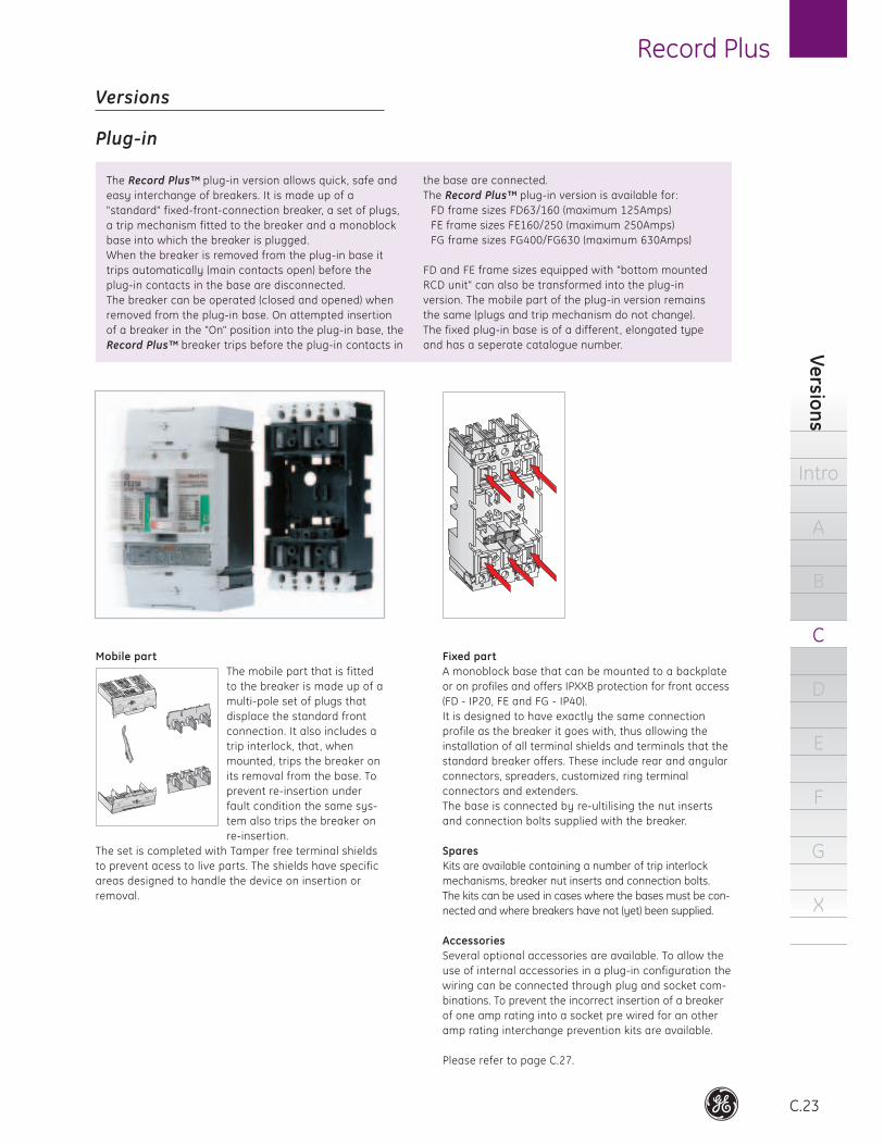
The Record Plus™ plug-in version allows quick, safe and
easy interchange of breakers. It is made up of a
"standard" fixed-front-connection breaker, a set of plugs,
a trip mechanism fitted to the breaker and a monoblock
base into which the breaker is plugged.
When the breaker is removed from the plug-in base it
trips automatically (main contacts open) before the
plug-in contacts in the base are disconnected.
The breaker can be operated (closed and opened) when
removed from the plug-in base. On attempted insertion
of a breaker in the "On" position into the plug-in base, the
Record Plus™ breaker trips before the plug-in contacts in
the base are connected.
The Record Plus™ plug-in version is available for:
FD frame sizes FD63/160 (maximum 125Amps)
FE frame sizes FE160/250 (maximum 250Amps)
FG frame sizes FG400/FG630 (maximum 630Amps)
FD and FE frame sizes equipped with "bottom mounted
RCD unit" can also be transformed into the plug-in
version. The mobile part of the plug-in version remains
the same (plugs and trip mechanism do not change).
The fixed plug-in base is of a different , elongated type
and has a seperate catalogue number.
Mobile part
The mobile part that is fitted
to the breaker is made up of a
multi-pole set of plugs that
displace the standard front
connection. It also includes a
trip interlock, that , when
mounted, trips the breaker on
its removal from the base. To
prevent re-insertion under
fault condition the same sys-
tem also trips the breaker on
re-insertion.
The set is completed with Tamper free terminal shields
to prevent acess to live parts. The shields have specific
areas designed to handle the device on insertion or
removal.
Co
mp
on
en
ts &
acc
ess
ori
es
Intro
A
B
C
D
E
F
G
X
Record Plus
C.24
Versions
Plug-in
A draw-out version allows one to visibly and positively
disconnect the mains supply from the installation.
Like on the plug-in device, interchanging breakers quickly,
safely and effectively is one of the key features of
Record Plus™ draw-out . It is made up of a breaker
("standard" fixed front connection version), a set of plugs
and a trip mechanism that are fitted to the breaker, a
monoblock base into which the breaker is plugged and a
metal support cradle.
The cradle allows for placing the breaker in one of three
positions:
Connected: Main and auxiliary contacts are fully
connected to the base
Test/Disconnected: Main contacts are disconnected.
Auxiliaries can be connected or disconnected. This allows
for a complete test of the secondary wiring/functionality
without having the mains connected.
Remove: Main and auxiliary contacts are fully
disconnected from the metal support cradle and the
plug-in base, the breaker can be removed.
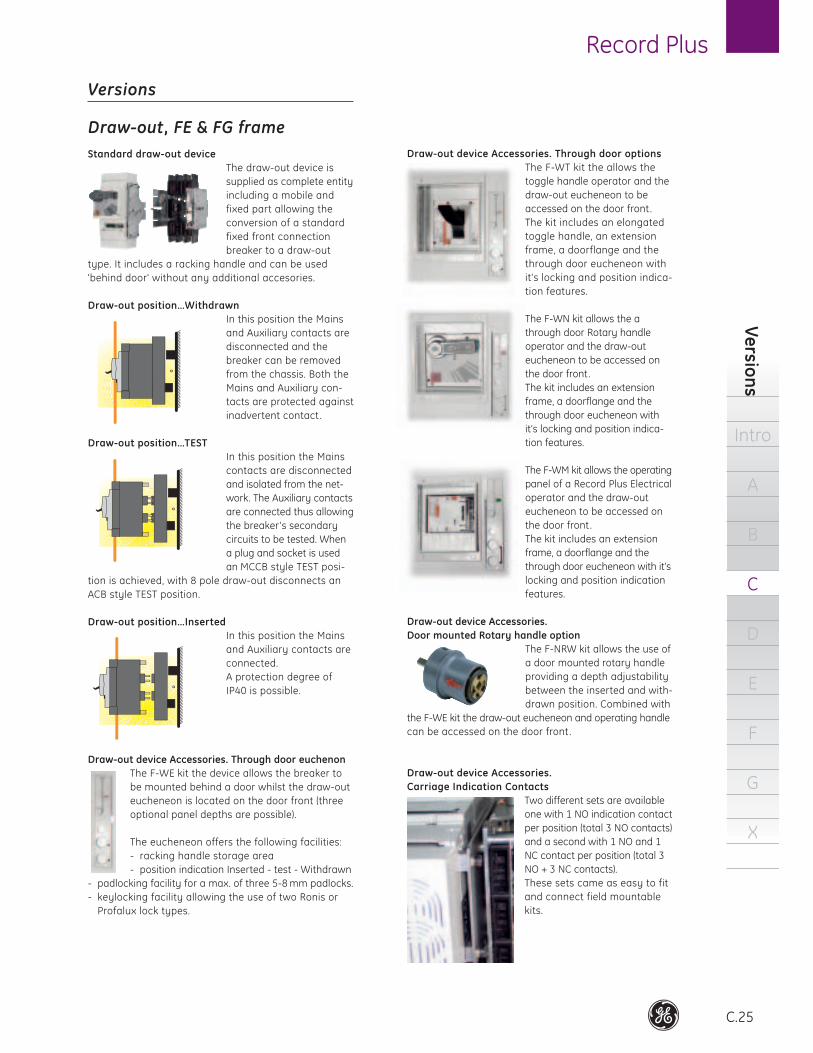
FE frame (max. 250A) & FG frame (max. 630A)
The draw-out device is supplied as complete entity
including a mobile and fixed part allowing the conver-
sion of a standard fixed front connection breaker to a
draw-out type.
Each kit contains a sturdy metal chassis with plug-in
base that serves as a fixed part and a kit allowing the
conversion of a fixed front connected breaker.
The moving part makes use of metal side supports,
multi pole plugs that displace the standard breaker
front connection system and a trip interlock system.
The Trip interlock system has an unique safety feature
that trips the breaker on removal from it’s base and
prevents re-insertion under fault condition by tripping
the breaker. Two Tamper free terminal shields prevent
acess to live parts.
The fixed component of the kit includes an integrated
standard plug-in base encapsulated in a sturdy metal
chassis. The base is connected by re-ultilising the nut
inserts and connection bolts supplied with the breaker.
All standard terminal shields terminals, rear connection
facilities & lugs available for the standard fixed front
conection breaker can be used with this plug-in base.
see page C.25 for more details.
FK frame (max. 800A) & FK frame (max. 1600A)
The draw-out device is supplied as complete entity
including a mobile and fixed part allowing the conver-
sion of a standard fixed front connection breaker to a
draw-out type.
Each kit contains a sturdy polyester l chassis with inte-
grated plug-in base that serves as a fixed part and a kit
allowing the conversion of a fixed front connected breaker.
The moving part makes use of metal side supports,
multi pole plugs that displace the standard breaker
front connection system and a trip interlock system.
The Trip interlock system trips the breaker on removal
from it’s base. Two Tamper free terminal shields prevent
access to live parts.
The cradle and plug-in base are integrated to form one
moulded part. Two types exist one with FRONT and one
with REAR connections both allowing the use of the stan-
dard connection lugs used on the device in fixed execution.
The FK frame draw-out system is always supplied with
a door frame suitable for use as a through door solution
and including a position indication system. The door
frame allows the locking of the device in draw-out posi-
tion with one or two Ronis 1104 B locks.
See Page C.27 for more details
Record Plus
C.25
Ve
rsion
s
Intro
A
B
C
D
E
F
G
X
Versions
Draw-out, FE & FG frame
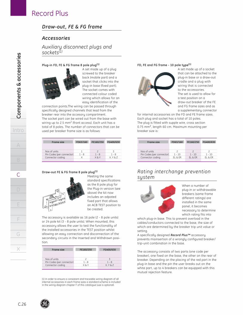
Standard draw-out device
The draw-out device is
supplied as complete entity
including a mobile and
fixed part allowing the
conversion of a standard
fixed front connection
breaker to a draw-out
type. It includes a racking handle and can be used
'behind door' without any additional accesories.
Draw-out position…Withdrawn
In this position the Mains
and Auxiliary contacts are
disconnected and the
breaker can be removed
from the chassis. Both the
Mains and Auxiliary con-
tacts are protected against
inadvertent contact .
Draw-out position…TEST
In this position the Mains
contacts are disconnected
and isolated from the net-
work. The Auxiliary contacts
are connected thus allowing
the breaker’s secondary
circuits to be tested. When
a plug and socket is used
an MCCB style TEST posi-
tion is achieved, with 8 pole draw-out disconnects an
ACB style TEST position.
Draw-out position…Inserted
In this position the Mains
and Auxiliary contacts are
connected.
A protection degree of
IP40 is possible.
Draw-out device Accessories. Through door euchenon
The F-WE kit the device allows the breaker to
be mounted behind a door whilst the draw-out
eucheneon is located on the door front (three
optional panel depths are possible).
The eucheneon offers the following facilities:
- racking handle storage area
- position indication Inserted - test - Withdrawn
- padlocking facility for a max. of three 5-8 mm padlocks.
- keylocking facility allowing the use of two Ronis or
Profalux lock types.
Draw-out device Accessories. Through door options
The F-WT kit the allows the
toggle handle operator and the
draw-out eucheneon to be
accessed on the door front.
The kit includes an elongated
toggle handle, an extension
frame, a doorflange and the
through door eucheneon with
it’s locking and position indica-
tion features.
The F-WN kit allows the a
through door Rotary handle
operator and the draw-out
eucheneon to be accessed on
the door front.
The kit includes an extension
frame, a doorflange and the
through door eucheneon with
it’s locking and position indica-
tion features.
The F-WM kit allows the operating
panel of a Record Plus Electrical
operator and the draw-out
eucheneon to be accessed on
the door front.
The kit includes an extension
frame, a doorflange and the
through door eucheneon with it’s
locking and position indication
features.
Draw-out device Accessories.
Door mounted Rotary handle option
The F-NRW kit allows the use of
a door mounted rotary handle
providing a depth adjustability
between the inserted and with-
drawn position. Combined with
the F-WE kit the draw-out eucheneon and operating handle
can be accessed on the door front .
Draw-out device Accessories.
Carriage Indication Contacts
Two different sets are available
one with 1 NO indication contact
per position (total 3 NO contacts)
and a second with 1 NO and 1
NC contact per position (total 3
NO + 3 NC contacts).
These sets came as easy to fit
and connect field mountable
kits.
Co
mp
on
en
ts &
acc
ess
ori
es
Intro
A
B
C
D
E
F
G
X
Record Plus
C.26
Draw-out, FE & FG frame
Accessories
Auxiliary disconnect plugs and sockets(1)
Plug-in FD, FE & FG frame 8 pole plug(1)
A set made up of a plug
screwed to the breaker
back (mobile part) and a
socket that clicks into the
plug-in base (fixed part).
The socket comes with
connected colour coded
wiring which allows for an
easy identification of the
connection points.The wiring can be passed through
specifically designed channels that lead from the
breaker rear into the accesory compartment .
The socket part can be wired out from the base with
wiring up to 2.5 mm2 (front access). Each unit has a
total of 8 poles. The number of connectors that can be
used per breaker frame size is as follows:
Draw-out FE & FG frame 8 pole plug(1)
Meeting the same
standard specifications
as the 8 pole plug for
the Plug-in version (see
above) the kit now
includes an adpated
fixed part that allows
an ACB TEST position to
be created.
The accessory is available as 16 pole (2 - 8 pole units)
or 24 pole kit (3 - 8 pole units). When mounted, this
accessory allows the user to test the functionality of
the installed accessories in the TEST position whilst
allowing an easy connection and disconnection of the
secondary circuits in the Inserted and Withdrawn posi-
tion.
(1) In order to ensure a consistant and traceable wiring diagram of all internal accessories in each frame sizes a standard scheme is included in the wiring diagram chapter F of this catalogue (use is optional).
FD, FE and FG frame - 10 pole type(1)
A set made up of a socket
that can be attached to the
plug-in base or a draw-out
cradle and a plug with
wiring that is connected
to the accessories.
The set is used to allow for
a test position on a
draw-out breaker of the FE
and FG frame sizes and as
a supplementary connector
for internal accessories on the FD and FE frame sizes.
Each plug and socket has a total of 10 poles.
The plug is fitted with supple wire, cross section
0.75 mm2, length 60 cm. Maximum mounting per
breaker size is:
Rating interchange prevention system
When a number of
plug-in or with drawable
breakers (same frame
different ratings) are
installed in the same
panel, it becomes
necessary to determine
which rating fits into
which plug-in base. This to prevent overload in the
cables/conductors connected to the base, the size of
which are determined by the breaker trip unit value or
setting.
A specifically designed Record Plus™ accessory
prevents misinsertion of a wrongly configured breaker/
trip-unit combination in the base.
The accessory consists of two parts (one code per
breaker), one fixed on the base, the other on the rear of
breaker. Depending on the placing of the red part in the
plug-in base and the pin the user breaks out on the
white part , up to 4 breakers can be equipped with this
mutual rejection feature.
FD63/160 FD63/160FE160/250 FE160/250FG400/630 FG400/630
Nos of unitsPin Codes (per connector)Connector coding
Nos of unitsPin Codes (per connector)Connector coding
11 - 8
X
21 - 10
EL & ER
21 - 8X & Y
21 - 10
EL & ER
31 - 8
X, Y & Z
21 - 10
EL & ER
Frame size Frame size
FG400/630
Nos of unitsPin Codes (per connector)Connector coding
21 - 8X & Y
31 - 8
X, Y & Z
Frame size FE160/250
Record Plus
C.27
Ve
rsion
s
Intro
A
B
C
D
E
F
G
X
Versions
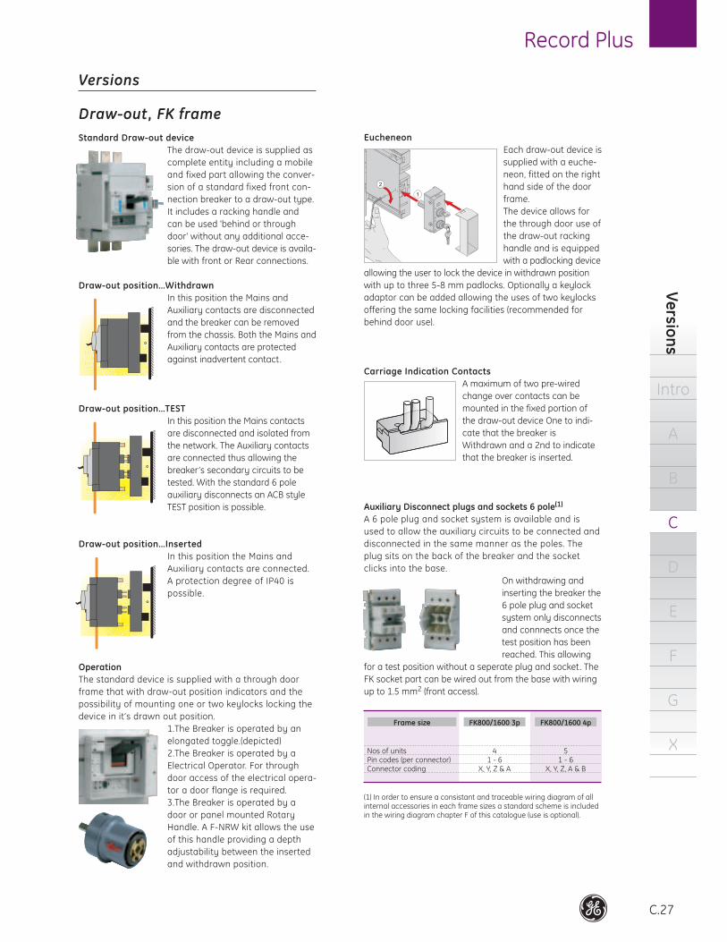
Draw-out, FK frame
Standard Draw-out device
The draw-out device is supplied as
complete entity including a mobile
and fixed part allowing the conver-
sion of a standard fixed front con-
nection breaker to a draw-out type.
It includes a racking handle and
can be used 'behind or through
door' without any additional acce-
sories. The draw-out device is availa-
ble with front or Rear connections.
Draw-out position…Withdrawn
In this position the Mains and
Auxiliary contacts are disconnected
and the breaker can be removed
from the chassis. Both the Mains and
Auxiliary contacts are protected
against inadvertent contact.
Draw-out position…TEST
In this position the Mains contacts
are disconnected and isolated from
the network. The Auxiliary contacts
are connected thus allowing the
breaker’s secondary circuits to be
tested. With the standard 6 pole
auxiliary disconnects an ACB style
TEST position is possible.
Draw-out position…Inserted
In this position the Mains and
Auxiliary contacts are connected.
A protection degree of IP40 is
possible.
Operation
The standard device is supplied with a through door
frame that with draw-out position indicators and the
possibility of mounting one or two keylocks locking the
device in it’s drawn out position.
1. The Breaker is operated by an
elongated toggle.(depicted)
2. The Breaker is operated by a
Electrical Operator. For through
door access of the electrical opera-
tor a door flange is required.
3. The Breaker is operated by a
door or panel mounted Rotary
Handle. A F-NRW kit allows the use
of this handle providing a depth
adjustability between the inserted
and withdrawn position.
Eucheneon
Each draw-out device is
supplied with a euche-
neon, fitted on the right
hand side of the door
frame.
The device allows for
the through door use of
the draw-out racking
handle and is equipped
with a padlocking device
allowing the user to lock the device in withdrawn position
with up to three 5-8 mm padlocks. Optionally a keylock
adaptor can be added allowing the uses of two keylocks
offering the same locking facilities (recommended for
behind door use).
Carriage Indication Contacts
A maximum of two pre-wired
change over contacts can be
mounted in the fixed portion of
the draw-out device One to indi-
cate that the breaker is
Withdrawn and a 2nd to indicate
that the breaker is inserted.
Auxiliary Disconnect plugs and sockets 6 pole(1)
A 6 pole plug and socket system is available and is
used to allow the auxiliary circuits to be connec ted and
disconnected in the same manner as the poles. The
plug sits on the back of the breaker and the socket
clicks into the base.
On withdrawing and
inserting the breaker the
6 pole plug and socket
system only disconnects
and connnects once the
test position has been
reached. This allowing
for a test position without a seperate plug and socket. The
FK socket part can be wired out from the base with wiring
up to 1.5 mm2 (front access).
(1) In order to ensure a consistant and traceable wiring diagram of all internal accessories in each frame sizes a standard scheme is included in the wiring diagram chapter F of this catalogue (use is optional).
FK800/1600 4p
Nos of unitsPin codes (per connector)Connector coding
41 - 6
X, Y, Z & A
51 - 6
X, Y, Z, A & B
Frame size FK800/1600 3p