recording technique o o o vol. 24. no. 505. … technique o o month o o vol. 24. no. 505. editor: f....
TRANSCRIPT
RECORDING TECHNIQUE
o
o MONTH
O o
Vol. 24. No. 505. Editor: F. J . C A M M {| AUGUST, 1948
mm
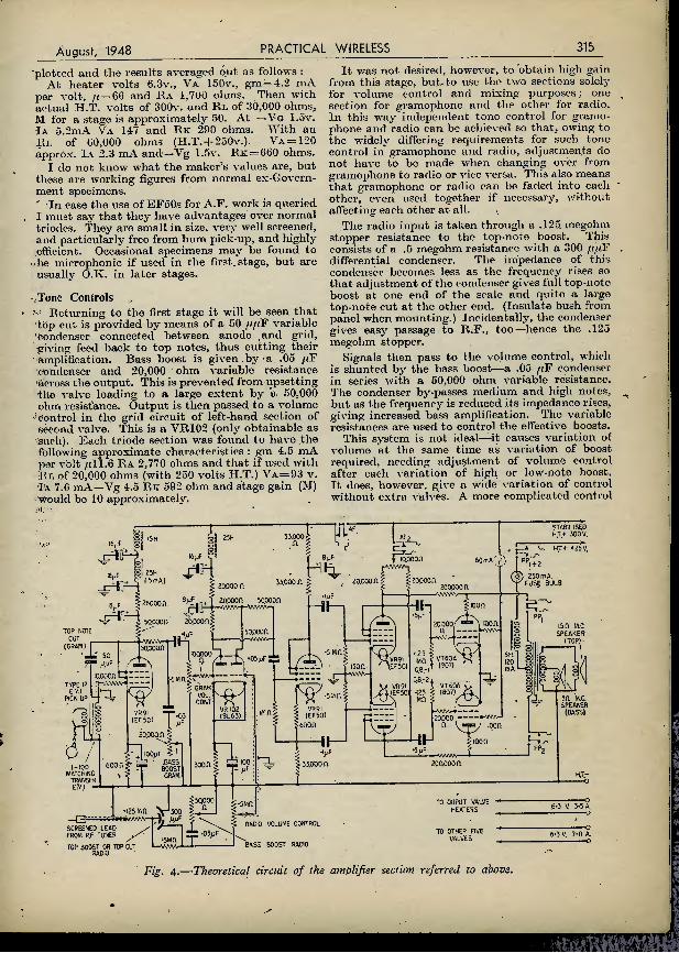
Sec Page 330
PRINCIPAL CONTENTS
3-Range Coil Pack Practical P.A. Working High-fidelity Radiogram Modulation
Television Servicing Examination Paper Home Intercom. System . , Simplicity of the Superhet Television Troubles

-PREMIER-
RADIO Co. MORRIS & CO. (RADIO) LTD.
LOUDSPEAKERS BY FAMOUS MAKER Sin. P.M. 2-3 ohms 6in. ,, 2-3 ,, 8in. ,, 2-3 ,, lOin. 2-3 ,, 12jn. .. 15 .. lOin. Energised. 2,000 ohm field
1011 16 6 17 6 23 6 85- 25- AUUUMULATORS.—2v. Bakelite-cased Accumulators by Oldhara. Dagenite. Exlde, etc. New and unused, unspillable vents. Tin. x 4in. x 2in. 8, 6 each. BATTERY CHARGER KITS.—6v. 1 amp. (tapped at 2v.). 22.6 : I2v. 1 amp., 27/6. These incorporate Metal Rectifiers and Transformers. For 200-250v. A.C. mains. H.T. ELIMINATOR AXJ> THICKLE CHARGER KIT.— Consists of a complete Kit of Parts to construct an H.T. Eliminator with an output of 120 v. at 20 m.a. and provision for Trickle Charging a 2 v. Accumulator. Two Metal Rectifiers are employed, with Circuit. 35/-. COLLARO ELECTRIC GRAMOPHONE MOTORS with 12in. turntable. A.C. only, 100-250 v.. £5/18/4. COLLARO ELECTRIC UNIT with Magnetic Pick-up and Auto Stop. A.C. only, 100-250 v.. £9/13/6. DITTO UNIT with Crystal Pick-up. A.C. only. 100-250 v. £11 2 2. COLLARO AUTO CHANGERS with Magnetic Pick-up. A.C. only. 100-250 v.. £22/4'4. CONRAD RIM DRIVEN ELECTRIC GRAMOPHONE MOTORS with 9in. Turntable. Fixed Speed (78 r.p.m.) for 200-250 v. A.C. only. £4 19'3. C.R. TUBES. VCR97. 6in. diameter, green screen. 4 v. 1 a. heater, 2,500 v. max. H.T. Complete with socket, in makers original cartons, 55/-. MULLARD M.W. 18-2 TELEVISION TUBES. Tin. diameter, 2 v. heater. 5KV max. H.T. Mazda Octal Base. £5/19/6, in maker's cartons. C.R. TUBES. We have available a large quantity of E.M.I.4/1 Cathode Ray Tiibes. Siin. diameter. Green screen, short persistence. 4 v. 1.3 a. heater. 800 v. H.T. Complete with- socket, 17 6 each. C.R. TUBES V.C.R.138 (equivalent to' E.C.R. 35). < 3iln- diameter. Green Screen. 4 v. 1 a. heater. 1,200 v. H.T. Complete with socket and Mumetal screen, 49/6 each. RECTIFIERS.—Westinghouse J.50 Rectifiers, 7/6 each.
OFFER.—High-grade Double using balanced armature units. D.C. Res. 60 ohms. SPECIAL HEADPHONE Headphone:., I , 3/6 per pair, 5 6 two pairs. Matching transformer if required 2/6 each: SPECIAL VALVE OFFER
6F6 10 6 VU134 (HVR2) 10- 6V6 — 8 6 VU39 (R3) 9 - CV6 — 5/- VR137 (EC52) 5- VR65 (SP41. 6.3 v.) 5/- VR136 (EF54) 76 VR92 (EA50) 5/- VS70 (7475) 76 VR56 (EF36) 6- VT60A (807 Ceramic) 10- VR78 (Dl) 2 6 717A — 7/6 VR55 (EBC33) 5/- 12SH7 — 7/6 VT86 (6K7 met) 10 6 12SL7 — 10- VR503 (KT33C) 10- 12A6 — 7/6 VR57 (EF32) 7/6 VR91 (EF50) 66 954 — 5/- RL18 — 12 6 6B8 — 5/- 5Z4 — 7 6 6B7 — 5 - 6K8 — 6/6 1S5 — 5- MAINS TRANSFORMERS at exceptional prices. All are heavy duty and robust. All 230 v. 50 cycles input. Price 3 500-0-500 v. 150 m/a. 4 v. 21 a.. 4 v. 5 a.. 4 v. 1 a. 35'- 4 865-0-865 v. 500 m/a. tapped at 690 v. and 760 v. 4 v. 3 a. 75 - 35 300-0-300 v. 250 m/a. 4 v. 3.5 a., 6.3 v. 5-7 a., 6.3 v. 1-2 a. 35 - 30 30 v. 4 a. 20 - 31 40 v. 3 a. and 104 v. 1.5 a. (auto-wound) 21 - 32 700-0-700 v. 150 m a. and 1,000 v. 30 m/a. 4 v. 1 a., 4 v. 4 a. 40.'- 33 38 v. at 2 a. tapped at 36 v., 34 v., 32 v. 15 - 34 1500-0-1500 v. 120 m a. 4 v. 2-3 a.. 4 v. 2-3 a. 55 - 34a 1500 v. 5 m a. and 1500 v. 5 rn/a. 4 v. 2 a.. 2 v. 2 a., 2 v. 2 a. 25 - 49 275-0-275v. 120 m a. 5v. 2a.,6.3v. 2.5 a., 6.3v. .3 a. ct. 29 - 42 500-0-500 v. 170 m/a. 4 v. 4. a. 35- 43 4 v. 20 a. 25 - 46 100 watt auto 230 v. 150 v. 100 v. 50 v. 12 6 OUR 1948 LIST IS AVAILABLE. All enquiries mus*
be accompanied by a 2\d. stamp. ALL POST ORDERS TO JUBILEE WORKS, 167, LOWER CLAPTON ROAD, LONDON, E.5. 'Phone : Amherst 4723 ALL CALLERS TO 169, FLEET STREET, LONDON, E.C.4.
'Phone : Central 2833.
VALUE
FROM VALLANCE'S MIDGET MAINS TRANSFORMERS, TYPE MT/MI.— A small drop-through transformer suitable for Signal Generators, Midget Receivers, V.F.O.s and many other applications where size is the limiting factor. Primary : 20012301250 volts, with earthed static screen. Secondaries : 260-0-260 volts, 80 m.a, 0-4-5 volts 2 amps. 0-6.3 volts 3 amps. Dimensions, 3im. x 2iin. x 2m. Price 22/6. ENAMELLED COPPER WIRE 4oz. reels. 18 and 20 S.W.G., 1/8 ; 22 S.W.G.. 2/- ; 24 S.W.G.. 2/3 ; 26 S.W.G.. 2/S- 28 S.W.G., 2/6 ; 30 S.W.G., 2/8 : 32 S.W.G., 2/10 ; 36 S.W.G., 3/5 ; 38 S.W.G., 31- ; 40 S.W.G.. 4/3. BAKELITE SHEET.—Jin.' thick. Sizes : I2in. x 8in., 5/1 • lOin. x Sin.. 4/3 ; lOin. x 6in., 3/5 ; 8rn. x Sin., 2/10 ; 6in. x 6in ' 2/3 ; 6ii>. x 4in., 1/8. HEADPHONES.—An extremely sensitive pair of lightweight 'phones of American manufacture. Ideal for crystal sets, and also with low impedance output, but can be matched to high impedance lines with a 4-1 (approx.) transformer. Complete with rubber cushioned ear-pads, leather head-bands, cord and jack plug. Individually boxed and new, 3/9 per pair, plus I/- post and packing. CARBON THROAT MIKES.—A lightweight:, compact and sensitive unit, complete with elastic scrap, cord and 2-pin plug. American manufacture—brand new, 1/5 each.
Q-MAX " CHASSIS CUTTERS.—For an easy, quick way of cutting holes in sheet metal or aluminium. The cutter consists of a die, a punch, and an Allen screw. Available in the following sizes : |in. Button base. 9/6 ^in. D8G, 9/6, plus 9d. for key. IJin. Octal base, IJin., IJin., all at 12/6, plus II- for key.
SPEEDY POSTAL SERVICE C.W.O. or C.O.D. When sending C.W.O. please include II- (mininjum charge)
for post and packing. VALLANCE & DAVfSON, LTD.
144, Briggate, Leeds I. 'Phone : 29428/9.s
Staff call signs :—G2HHV, G8SX, G3ABD, G3CML,
CoimoiNseiii* GRAMOPHONE MOTOR NOW READY «
f
■'s W.
Npccificaii 011 .Voltage : 200-250 volts A.C., 50 cycles.
Rim drive with speed variation. No governors and no gearing. Heavy non-ferrous turn-table, machined to run dead true, fly-wheel action«-no " WHOW " Main turntable spindle hardened, ground and lapped to mirror finish, running in special phosphor bronze bearings. Motor runs in needle-point, self- adjusting bearing. Motor Board -fin. plastic. Pressure on Drive-Wheel released when not in
use, to obviate forming flats and noisy action.
-Apply to- Albion Electric Stores, 125 Albion Street, Leeds, 1, or to Lawton Brothers (Sales) Ltd., Henry Square, Ashton-under-Lyne.
A. R, SUGDEN & CO. (ENGINEERS) LTD BRIGHOUSE, YORKS.

August, 1948 PRACTICA1 WIRELESS 309
, fatSetS
No sec is complete j without at least one Stentorian speaker toallow you to enjoy I the luxury of radio away f rom the | receiver — in the kitchen or bedroom, for instance. And the quality of the most magnificent set will be matched without fault, for each Stentorian pro- vides a high level of output, with distortion-free reproduction—and is housed in a handsome wooden cabinet of perfect acoustical construction, incorporating matching transformer and volume control.
Ask your locaj- dealer about them. Prices from 39/6d. with Sin. unit, to £5 15s. 6d. with 9in. unit.
tentorian —the finest extra SPEAKER for any set WHITELEYELECTRICALRADIOCO. LTD.,MANSFIELD,NOTTS
CONVERTED R.I 155 RECEIVER In response to numerous requests, we can now supply this famous R.A.F. Communications Receiver modified for normal mains use, and complete with speaker. Unlike other modifications, the power pack, output stage and speaker are fitted into a specially designed cabinet which fits on top of the receiver. The whole makes a presentable installation without using several small units connected by unsightly trailing wires. A really superb Communications Receiver covering 75 kcs.- 18.0 mcs. in five wavebands. Fully illustrated leaflet available on request. Only £18/10/- (carriage 12/6. returnable transit case 10/-), or the unmodified version £12/10/-. RECORD INSULATION TESTERS.—A special offer of ex-Govt. Insulation Testers by " Record." 500-volt pressure. Brand new and perfect. Only £8/10/-. TRANSMITTING PANEL.—An ex-R.A.F. Transmitting Panel containing shoals of TX gear, including two large .0002 mfd. variable short-wave condensers, coils, variable induc- tances. switching, 2.iin. bar and knurled knobs, etc. etc. Br'and new in makers' cartons. Only 9/11 (carriage, etc., 3/6)^ EX-R.A.F. BATTERY AMPLIFIERS.—A very fine battery amplifier used by the R.A.F. for intercommunication in aircraft. Ideal for use with a pick-up or home intercomm., etc. Com- plete with valves, types QP2I and 210 LF. Operating voltages 2v L.T. and I20v. H.T. Brand new in transit case. Only 25/- (carriage, etc., 2/6).
CWO Please. SAE for lists.
U.E.I. CORP., The Radio Corner,
138, Grays Inn Road, London, W.C.I.
(Open until I p.m. Saturdays, we are 2 mins. from High Holborn, 5 mins. from King's X.)
LOOK! Build Your
OWN TELEVISION
RECEIVER!
At the absurdly low cost of £7.1 7.6, we will supply you with a brand new pair of ex-R.A.F. equipments, as illustrated, which with the addition of a suitable power supply and with minor modifications, will constitute a complete television receiver. These units are available in several forms as detailed below. A brief specification follows ;—
THE RECEIVER UNIT — type R3I70A : A 15-valve receiver covering television frequency, with separate oscil- lator section. In- cludes its own power supply which is only- suitablfe for 2,000 cycles and will not be used. The trans- former, however, will serve as a method of charging ; details of this will be issued. Valve line up : 8 of EF50, 2 of RL37, I of RLI6, I of HVR2, I of R3, I of EA50, I of CVI88. The valves alone are worth more than the tpst of this equipment. Packed in wooden transit cases FULL CIRCUITS.
THE INDICA- TOR UNIT— type 6 A complete vision unit comprising 6m. Electrostatic CRT., 4 of EF50, 3 of EB34 valves. See Wireless World, May, 1948, issue for full cir- cuits and modifi- cations. Will also make a very fine Oscilloscope. Two models, available, new and slightly used. Full modification instructions and circuits.
Matched pair of brand new units. £7.17.6 (15/- carriage and pkg.). Matched pair of units comprising brand hew R3I70A and slightly soiled Indicator, but in good condition, £7.7.0 (15/- carriage and packing). R3I70A (brand new) only, £4.5.0 (7/6 carriage and p^CkingX Unit type 6 (brand new) only, £3.19.6 (7/6 carriage and packing)" Unit type 6 (slightly used) only, £3.5.0 (carriage and packing 7/6)^ Callers for indicator units preferred to obviate possible transit damage.
Type R3I70A Complete with 15 New Valves— and BRAND NEW
Indicator Unit Type 6 Complete with 6" C.R.T. and 7 valves
BRAND NEW
I ARE YOU A REGULAR SUBSCRIBER TO THE FAMOUS M.O.S. NEWSLETTER ? If not send 6d. for current copy, and subscription form.
MAIL ORDER SUPPLY CO. Depi. PW. 3, Robert Street, Hampstead Rd., London, N.W.I
CALLERS to 24, New Road, E.t Steeney Ore en 27S0-39OS

310 PRACTICAL WIRELESS Augusf, 1948
D.C. Voltage 0—75 millivolts 0—5 volts 0—25 „ 0—100 0—250 „ 0—500 „
D.C. Current 0—2.5 mi Hi amps 0—5 0—25 0—100 0—500
A.C, Voltag 0—5 volts 0—25 0—100 0—250 0—500
Resistance 0—20,000 ohms 0—100,000 „ 0—500,000 „ 0—2 megohms 0—5 0—10
GUARANTEE: The registered Trade Mark " Avo " is in itself a guarantee of high accuracy and superi- ority of design and craftsmanship. Every new AvoMinor is guaranteed by the Manufacturers against the remote possibility of defective materials or workmanship.
'JuZ^LSyLOn ■ I K C IB BC %I
testiwo
A dependably accurate instrument for testing and fault location is indispensable to the amateur who builds or services his own set Stocks are now available of these two famous " Avo " Instruments' It you have any difficulty in obtaining one locally, please send us the name and address of your nearest Radio Dealer.
The Universal AvoMinor (as illustrated) is a highly accurate moving-coil instrument conveniently compact, for measuring A.C. and D.C. voltage D.C. current, and also resistance; 22 ranges of readings on a 3-incn scale. Total resistance 200,000 ohms.
Stze 4lins. x 3itns. x ilins. Complete with leads, inter- Nett weight : 18 ozs. changeable prods and croco- Price : £8 : 10 : 0 book.CUpS' imtructim
The D.C. AvoMinor If arf r-'nC'VmOV'n8 c0'' met®r providing 14 ranges of readings Pr-if: • volt:age, current and resistance up to 600 volts, 120 rrPoShmasnd 3 me8ohms respectively. Total resistance
Size: 4hns. xjlins. x ilins. Complete as above. Nett weight: 12 ozs. . « . . . Price : £4:4:0
So/e Proprietors and Manufacturers : AUTOMATIC COIL WINDER & ELECTRICAL EQUIPMENT CO., LTD Winder House. Douglas Street, London, S.W.I 'Phone : Victoria 3404-9
BUILT
TO
LAST
Attention to detail and finish makes R.M. Mains Transformers the best value on the market today. Their sound mechanical and technical design and low operating temperature make long service a certainty.
<s\s\s\s\
M ,
:
iiiliil mm
IT
ll 111 Mains Transformers
d V. & 6.3 V. types. 75 M/A .. 37/6d, 120 M/A .. dS/-.
ELECTRIC LTD TEAM VALLEY M.C.T. RANGE. GATESHEAD

August, 1948 PRACTICAL WIRELESS 311
D
EVERY MONTH VOL. XXIV. No. 505 AUGUST, 1948
COMMENTS OF THE MONTH
C and PRACTICAL TELEVISION ) fcLtot f.J.CAMM
16th YEAR OF ISSUE
BY THE EDITOR
Reduction of Purchase Tax
THE Chancellor of the Exchequer may wave his magic export wand, and impose heavy purchase tax on radio and kindred equip-
ment to force manufacturers to export, but- he overlooks one or two important points.
In the first place he is mistaken in his belief that the British public will bear any financial burden which he imposes. The second is that you cannot expect other countries to bear the cost of the Social Security schemes instituted in this country. Manu- facturers have been advised that in order to provide dollar credits and foreign currencies we must export a large percentage of our goods, and this manufac- turers have been unable to do. because our prime costs are higher than those of competitive countries which believe in getting back their world markets before considering other questions.
When this was pointed out to the Chancellor of the Exchequer, manufacturers were advised to sell their goods abroad at cost or even less and to make their profits out of home sales. This is strange advice, because it means that the British public is to pay excessive prices in order to meet the losses incurred on export, and that manufacturers, representatives of private enterprise, are expected, after all the criticism they have suffered, to bolster up this new policy.
This means that the Exchequer is exploiting the British public. The purchase tax was designed, of course, to kill home sales. This it has effectively succeeded in doing, and as high production costs have also suc- ceeded in hampering exports, the ill-considered export policy has destroyed both markets.
The Chancellor also did not take into consideration apparently the valuable advice given to him by- trade associations. Realising his mistake he has considered the reduction of purchase tax to 33?, per cent, on all domestic, portable and vehicle radio wire- less, including television, valves, and cathode-ray tubes.
We do not think that in doing this the Government is recognising the vital importance of radio in the life of the country, as a representative of the Radio Coimcil seems to suggest. We think the Government is more concerned with unemployment than any consideration for the public. The
latter has done a public service in refusing to pay the further impost at a time when the Government is pegging wages and telling manufacturers that prices have to come down.
It may be that the Chancellor, on second thoughts, in spite of the advice given to him by the R.I.C., has acted too late, and that the public will not be tempted to buy radio receivers even with the purchase tax at 33J per cent.
The most effective way of forcing down prices is for the public to refuse to buy. The effect of the two increases since last autumn and the com- mercial uncertainty of the last two months have between them generated severe difficulties which it will take some months to overcome. The industry will take some time to revive from the blow it received in the April Budget. The industry has evolved a recovery plan, but it is not until the autumn that we shall be able to test public reaction.
The whole principle of purchase tax is wrong in peacetime. A healthy home trade should first be encouraged and any excess overspilled into the export markets. The public has deserved after five years of war a replenishment of those goods it was unable to- buy during the war.
The country at present is running on a System of taxation and control on a wartime basis, whilst other countries.
Editorial and Advertisement Offices : " Practical Wireless,"' George Newnes, Ltd., Tower House. Sonthamptou Street, Strand, W.C.2. 'Phone : Temple Bar 4363. Telegrams : Newnes, Rand, London.
Registered at the G.P.O. -lor transmission b; Canadian Magazine Post. The Editor will he pleased to consider articles of a practical nature suitable for publication in " Practical Wireless" Such articles should be written on one side of the paper only, and should con- tain the name and address of the sender. Whilst the Editor does not hold himself responsible for manuscripts, every effort will be made to return them if a stamped and addressed envelope is enclosed. All correspondence intended for the Editor should be addressed : The Editor, " Practical Wireless," George Newnes. Ltd.. Tower House, Southampton Street. Strand. W.C.2. Owing to the rapid progress in the design of wireless apparatus and to our efforts to -keep our readers in touch ■with the latest developments, we give no warranty that apparatus described in our columns is not the subject of letters patent. Copyright in all drawings, photo- graphs and articles published in " Practical Wireless" is specifically reserved throughout the countries signatory to the Berne Convention and the U.S.A. Reproductions or imitations of any of these are therefore expressly forbidden. " Practical Wireless" incorporates " Amateur Wireless."
particularly some of those which we fought to liberate, are rapidly shedding controls. It is a healthy sign indeed that the public is turning. It is, indeed, adopting the methods which have been found effective by particular sections of the public in imposing their will, namely, we think there is a strike of purchasers. It is not an organised strike, it is just that conditions have been made so onerous that people have stopped buying. As a result the Chancellor can see the effect of killing home sales at a time when exports are declining.
Several firms have either closed or have sacked a goodly percent- age of their workers who are unable to find jobs in other branches of the industry, which finds itself in the same boat.
It is our view that the purchase tax on wireless equipment should be removed altogether. There is little wonder that people are saving less.

312 PRACTICAL WIRELESS August, 1948
ROUND THE^^OF'WIRELESS
Broadcast Receiving Licences yHK following statement shows the approximate
numbers of licences issued during the year ending, April 30th, 1948.
Region. London Postal Home Counties Midland North Eastern North Western South Western Welsh and Border
Total England and Wales Scotland Northern Ireland
GRAND TOTAL
Number. 2,102,000 1,472,000 1,605,000 1,737,000 1,455,000
973,000 649,000
9,993,000 1,060,000
183,000
11,236,000
This number includes 49,200 television licences, an increase of 3,650 over the previous month.
Prosecutions in April for operating wireless receiving apparatus without a licence numbered 591.
Ice-screens CUPPRESSORS to eliminate interference with
television reception have been fitted to the engihes of 500 vans and cars of T. Wall and Sons, ice-cream and sausage manufacturers. The device screens the radiation of electrical impulses which cause flashing on television receiving sets.
" Although the G.P.O. are fitting suppressors to their transport," says Mr. Cecil W. Rodd, chairman of Wall's, " we believe wo are the first private firm to introduce them. We hope that other organisations will follow suit, since at present enjoyment of television pro* grammes is often marred by this typo of interference."
Walls recently equipped a num- ber of their vans with car radios for the benefit of their drivers on long-distance runs.
units and six motor-driven tilting couches, as well as the latest in ultra short-wave electro- medical treatment equipment.
Hospitals in various parts of the Argentine will be equipped with these installations and it is hoped that the present consignment will, be the fox-e- runner of many more.
Ekco " On the Air" 'T'HE last broadcast in the recent series of " Worka
Wonders" programmes took place from the stage of the Ekco canteen, at the Southend factory of E. K. Cole, Limited.
Presented and produced by Brian Johnston, the show consisted of eight turns from the following members of the Ekco Players: Winnie Clark, Bill Eraser, Mona Williams, Jack Cowlishaw, Len Jones, John Spreadborough, Norma Bourne, Frank Cove, John Cole, and the Len Chandler Orchestra. .The artistes are representative of all the company's divisions—radio, heating, lighting and plastics—arid: were fully supported by a largo and enthusiastic; Sludience including many throughout the organisa- tion listening-in on Ekco radios.
Training Telecommunications Engineers CTARTING next month (September) at Norwood
Technical College, the London County Council is to provide a new course to train young men for careers in electronics and telecommunications engineering. It is being arranged with the full
X-ray Equipment for Argentine A\NE of the largest consignments
of X-ray equipment ever to leave these shores sailed from the Port of London recently in the s.s. Highland Princess.
Bound for Buenos Aires, this equipment is worth £20,000, and will earn many valuable dollars for Britain in her fight for recovery. The consignment consists of appar- atus manufactured by Philips Electrical, Ltd., London, and comprises six heavy duty diagnostic
iiilii
liiiaM
m
Presentation of the Eddy stone <c 640 55 Receiver at Grimsby Town Hall. Left to right : Mr. R. Jennison {GzAJV), the winner; the Chairman of the G.A.R.S. ; Mr. W. Grieve (GsGS), Chair- man of the Presentation Committee y the Mayor of Grimsby {Councillor W, B. Bailey, ].P.) ; Mr. A. C. Edwards (G6X]),
Director, Stratton & Co., Ltd.

August, 1948 PRACTICAL WIRELESS 313
support of the radio industry, and during the two years of the course the students will have at least six weeks' practical experience with one or more firms producing telecommunications equipment. They will learn to design, build and maintain a modern radio receiver, and will study the newest developments in this rapidly expanding field— television, radar, frequency modulation and ultra- high-frequency techniques ; many of their lecturers will be specialists from industry and technical establishments. Further information can be had from the Principal, Norwood Technical College, Knights Hill, S.E.27 (Telephone: GIPsy Hill •2208).
Radio Research HTHE B.B.C., for the first time in its career, has
appointed a scientific committee to advise on research in correlation with outside concerns. Its appointment is recognition of the important developments pending in frequency modulation, television and other phases of broadcasting.
Sir Edward Appleton, 55, secretary of the Department of Scientific and Industrial Research, who was recently awarded the Nobel Prize for radio research, is chairman, Sir John Cockcroft, 51, director of the Atomic Energy Research Establish- ment, will be vice-chairman.
Amplifier for M.C.C. School A COMPREHENSIVE amplifying system by
Philips Electrical, Ltd., has been installed, to the order of the architect, Mr. Howard V. Lobb,
K V
At the Bourne Secondary School the science master. Air. Fenton, demonstrates the control console to a few pupils.
F.R.I.B.A.. in ono of the mo.st up-to-date schools, in this country. This is the Bourne Secondary Modern School, Southbourne Gardens, Ruislip, Middlesex.
The main amplifier has been installed in the assembly hall with four microphone positions on the stage, while automatic priority over all other
'signals is taken by the microphone in the head- master's study. Loudspeakers have been fitted in the assembly hall and each of the eighteen class- rooms. Thus staflf and pupils, individually or collectively, can be summoned or addressed by the headmaster at any time ; in the ease of general announcements, the waste of time by assembly in the hall has now been obviated.
The new system, by incorporating a radio unit, permits B.B.C. broadcasts to schools to be relayed throughout the building if required, and the system is also used for dramatic productions and concerts performed by the pupils in the assembly hall, whiph has been treated to render it acoustically suitable.
Grimsby Radio Exhibition A UNIQUE ceremony took place at the Grimsby
Town Hall on the evening of Friday, May 7th, when the Mayor of Grimsby, Councill r W. B.
Bailey,' J.f'., presented an Eddystone "(>40" communications receiver to Mr. Roger Jennison (G2AJV), the winner of the recent competition organised by Stratton & Co., Ltd.
To mark the occasion the Grimsby Amateur Radio Society organised an amateur radio exhibition, which was open to the public for the whole evening. A very good show was put on. with many excellent examples of amateur constructed transmitters, re- ceivers and auxiliary equipment. Much interest was taken in t lie actual
. operation of the club station (GiiCNX/A), which was active on the 3.r> Mc/s band and made many contacts during the evening.
Radio Funerals TT is reported that two-way radio
for funerals is planned by the Catholic archdiocese of Chicago. An application was filed with the Govern- ment recently to set up a permanent land station and two mobile field units
- at Mount Carmel cemetery near Chicago.
According to the petition submitted by the Rev. William P. Casey, cemeteries director, radio communication among cemetery workers would eliminate confusion when several funerals are handled.
A
Relayed Television TELEVISION show using the delayed tech- jaique was presented for the first time recently
at the Paramount Theatre in New York City. The broadcast consisted of two amateur boxing
bouts. It was sent by 7,000 megacycle microwave relay from the arena to the top of the Daily News building and from there again relayed to the top of the theatre building.
At the theatre the picture was transposed almost instantaneously on to 35 m.ra. film by a special recorder, and the film was projected through the standard 35 m.m. projector. Only 66" seconds elapsed from the time a scene was broadcast to the time it appeared on the screen.

314 PRACTICAL WIRELESS August, 1948
High-fidelity
This Month C. W. HAGE Gives Details of
Chassis THE size used was 10Jin. x 9in., and was 2{in.
deep. Plywood stained and polished was used as a front panel. The chassis was provided with
complete screening, i.e., base-plate, and internal screens inside chassis between each stage.
The coils, tuning condenser and valves are mount- ed above chassis as shown on diagram so that each stage has its own components above or below the chassis, giving the shortest leads. On the front of the panel are mounted tuning indicator, demodulator diode bias potentiometer, and wave- change switch at top; tuning knob and dial in centre, and A.V.C./manual switch at bottom left. R.F. gain control is at bottom right. Aerial and earth connections are brought out to a 6-pin ceramic valve base (U.X. type)—two large pins both used for earth, and smaller sockets for aerial taps on primary coil (added) and original (Cossor) aerial input connection.
Power leads are taken from a 5-pin plug and socket at back of chassis to power unit.
Each stage of set has its own earth point on the chassis and a lead to this is taken from frame of three-gang condenser for each section.
Special Pointers I had a great deal of trouble with the .05 and
.1//F decoupling condensers. Those commercially; available appear to be extremely variable and develop leaks. While even a 10 megohm leak will not greatly affect an anode or screen by-pass con- denser (except that its early complete demise is extremely probable), I object to such a condenser in an A.V.C. system, where very high insulation resistance is imperative. As 1,000-volt working 0.01—.1 /xF mica condensers are now available at Is. 6d. each (ex-Government), it is suggested that these be used wherever possible.
It is suggested that the leads to top caps (grids) of V^, V2 and V4 be screened and top cap connectors bo used. The low capacity coaxial wire lead is the best type I find. The grid lead of V4 is the danger point, as it carries high R.F. voltages easily leaking back to earlier stages with subsequent instability. Tuning dial and also tuning indicator are illuminated by two small 12-volt bulbs run from the 6.3 volt heater supply. Eight-volt bulbs can be used if desired and will give a brighter light but need frequent renewing. Heater leads to valves should be twisted and kept as near chassis as possible. Run grid (and anode) leads as short and well spaced as possible and connect screen grid bypass condensers direct to S.G. contacts on valveholder—do not make a nice neat job with " group boards " for resistors and condensers, it encourages instability.
Adjustment and Lining Up With 250 volts H.T. and 6.3 volts A.C. available
from power pack, connect aerial to one of the aerial taps, e.g., " A100 " or " AloO." Put A.V.C.j
Radiogram-2
the A.F. Amplifier Section of the Radiogram
manual switch on A.V.C. position and turn R.F. gain control well down. Tune in a station at lower end of medium wave-band, e.g., European News Service, or the Light .Programme, if available in your area. Now adjust trimmers roughly to give best " dip " on meter, i.e., deepest dip when tuned over the station. Remove aerial lead and adjust diode bias potentiometer slotvly until standing D.C. current through tuning meter is just reduced to zero. Reconnect aerial and again tune in a good, steady signal—best done during daylight. Now adjust trimmers to give sharpest peak (i.e. " dip''1') when tuned over station. If aerial circuit is pulled out of line by aerial capacity (especially if using coaxial feeder), reduce aerial tapping to A100 or AoO. This wi 11 reduce this effect but will also increase selectivity. Incidentally, fine adjustment of the trimmers will show up best if A.V.C./manual switch is put on " manual " temporarily, although care should bo taken when tuning over a strong signal (i.e., turn down manual control) or else tuning indicator needles may slam hard over and even stick !
Finally (on A.V.C.) adjust tuning indicator shunt so that needle tips just cover each other on your strongest signal. If this is a local station it may be necessary to use the manual gain control to avoid overloading the demodulator. If the output is not sufficient it can be increased by using a higher H.T. voltage for the triode section (cathode follower). Increased H.T. voltage increases the handling capabilities and also increases anode current and may reduce valve life if carried too far. As it stands the unit should have an output of 12 to 13 volts A.F., which should be more than sufficient for any normal amplifier.
A.F. Amplifier and Power Pack A way has been shown of obtaining a large
high-quality output (from the circuit given) - from any station giving primarily a clear, undistorted signal of good programme value.
It is now necessary to pass this signal into the A.F. amplifier in which it must be built up to a signal largo enough to operate the output stage, and also to introduce such frequency correction as may be required by deficienees in R.F. amplifier, A.F. amplifier, and in the loudspeakers used. In the circuit given it will be seen that the first • valve (VR91 or EF50) is used solely as gramophone pre-amplifier. An E.M.I, type 12 miniature needle pick-up is used with the special 1-100 step-up transformer supplied by the makers. The secondary leads are kept as short as possible by mounting the transformer near to the valve on the amplifier chassis.
This means longer leads on the primary side from the pick-up, but it has not been found necessary to screen these leads (about 18in. long in my case). It will be seen that the EF50 is triode connected, as are the other three EFSOs used, and as little data appeared to be easily available characteristic curves of several specimens so connected were
August, 1948 PRACTICAL WIRELESS 315
"plotted and the results averaged out as follows ; At heater volts 6.3v., Va 150v., gnv 4.2 mA
per volt, /{ = 66 and Ra 1,700 ohms. Then with actual H.T. volts of 300v. and Rl of 30,000 ohms, M for a stage is approximate!}' 50. At — Vc 1.5v. Ia 5.2mA Va 147 and Rk 290 ohms. With an Rl of 00,000 ohms (H.T. + 250v.). Va=120 approx. Ia 2.3 mA and—Vg 1.5v. R k — 600 ohms.
I do not know what the maker's values are, but these are working figures from normal ex-Govern- ment specimens. ' In case the use of EF50s for A.F. work is queried I must say that they have advantages over normal triodes. They are small in size, very well screened, and particularly free from hum pick-up, and highly efficient. Occasional specimens may be found to be microphonic if used in the first,stage, but are usually O.K. in later stages.
Tone Controls ' Returning to the first stage it will be seen that top cut is provided by means of a 50 ///(F variable 'condenser connected between anode and grid, giving feed back to top notes, thus cutting their amplification. Bass boost is given by -a .05 /(F Condenser and 20,000 ohm variable resistance across the output. This is prevented from upsetting the valve loading to a large extent by a 50,000 ohm resistance. Output is then passed t o a volume control in the grid circuit of left-hand section of second valve. This is a VR102 (only obtainable as such). Each triode section was found to have the following approximate characteristics ; gm 4.5 mA
■per volt /ill.6 Ra 2,770 ohms and that if used with Rl of 20,000 ohms (with 250 volts H.T.) Va=93 v. Ta 7.0 mA—Vg 4.5 Rk 592 ohm and stage gain (M) Would bo 10 approximately.
It was not desired, however, to "obtain high gain from this stage, but to use the two sections solely for volume control and mixing purposes; one section for gramophone and the other for radio. In this way independent tone control for gramo- phone and radio can be achieved so that, owing to the widely differing requirements for such tone control in gramophone and radio, adjustments do not have to be made when changing over from gramophone to radio or vice versa. This also means that gramophone or radio can be faded into each other, even used together if necessary, without affecting each other at all.
The radio input is taken through a .125 megohm stopper resistance to the top-note boost. This consists of a .5 megohm resistance with a 300 ///|F differential condenser. The impedance of this condenser becomes less as the frequency rises so that adjustment of the condenser gives full top-note boost at one end of the scale and quite a large top-note cut at the other end. (Insulate bush from panel when mounting.) Incidentally, the condenser gives easy passage to R.F., too—hence the .125 megohm stopper.
Signals then pass to the volume control, which is shunted by the bass boost—a .05 pF condenser in series with a 50,000 ohm variable resistance. The condenser by-passes medium and high notes, but as the frequency is reduced its impedance rises, giving increased bass amplification. The variable resistances are used to control the effective boosts.
This system is not ideal—it causes variation of volume at the same time as variation of boost required, needing adjustment of volume control after each variation of high or low-note boost. It does, however, give a wide variation of control without extra valves. A more complicated control
1 liooo.'i nr1\r-> jri
! . Ei
u >-..Vv -.v. •"Til—I no ■' li
100.000
l! 5Mn|r^ | GRAM VOL. ■n
.'r* V v
-AV.V# 20.000 ^
|ioon —A.VA5A, t p^T i!—
[
I
•125 MO X-,300 S-AWA y |- >jpF
X
Fig. 4.— Theoretical circuit of the amplifier section referred to above.

316 PRACTICAL WIRELESS system using two extra double triodes has been worked out and tried and worked well, but this more simple system was installed owing to demands on space. It will be seen that the outputs from both triode sections are taken to input of phase-splitter valve through isolating 50,000 ohm resistances. These, of course, cause further loss, so that the amplification obtained by the double triode stage is lost in the tone control and isolating networks. However, ample gain is available more than fully to load the output valves.
The Phase Inverter The phase inverter circuit is quite straight-
forward and normal and again uses an EF50, triode connected. Half of its load is in the anode circuit, half in the cathode circuit, and care should be taken to use load resistors (33,000 ohm) which are equal in value. The slight unbalance due to the 600 ohm cathode resistor is compensated for in the intermediate push-pull stage, again consisting of triode-connected EFoOs, but with lower values of load resistance and of cathode resistor to deal with the-large voltage swings without distortion. The anode loads are -each of 20,000 ohm fixed and a 10,000 ohm potentiometer. H.T. lead is taken from the moving arm, variation of this potentiometer allowing balancing of the gain on each side of the amplifier to be adjusted until gain is equal.
Output then passes via .5 //F condensers to the push-pull 807 output stages, and here there are several points to explain. It was decided to use 807s (or UT60A) as these are easily available ex-Government types and will be found to be somewhat more hardy than the 6LG type.
After some experiment it was found that best quality was obtained (with extremely high output power) if the 807 was used with stabilised screen supply and fixed bias. Unfortunately, fixed bias causes the valve to be much less tolerant of high grid-leak values, .2 megohm being about the highest grid-to-earth resistance which can be used without danger of grid blocking occurring on strong signals. As far as possible throughout the amplifier, coupling condenser leak ratios have been kept at .05 or better (e.g., .1 pF and .5 megohm or .05 /(F and 1 megohm) to reduce bass attenuation and phase change as far as possible, so that with the output valve grid leaks at about .1 megohm a .5 yF coupling condenser from previous stage were necessary. Some considerable trouble has been experienced with these coupling condensers, many commercially available having relatively low insulation resistance. Those at present in use are large 1,000 volt working types and were " meggered " before use and found to be O.K.
Allowing for the .125 megohm grid leaks actually used and 20,000 ohm grid stoppers, even with maximum bias from the bias pack the total grid- to-earth resistance is less than 200,000 ohms. Both anode and screen stoppers of 100 ohms, are used and present parasitic oscillation. Approxi- mately 10 per cent, negative feedback is used direct from each output anode to the anode of its driving value via a 200,000 ohm resistance. This with the 20,000 ohm anode load of the previous valve forms a potentiometer giving about 10 per cent, feedback. These have been tried as variable resistors, but they have not been found to have any advantage.
Augusl, 1948 Owing to the use of push-pull, even harmonies
are cancelled out, and as the amount of odd harmonics produced by triodes is very low (especially when care is taken that they are running well on the straight part of the characteristic and never overloaded) the distortion produced by the amplifier up to the grid circuits of the 807s can be neglected. With push-pull beam tetrodes without feedback, distortion when well driven will'be mo'stly third, fifth and seventh harmonics. These can be reduced: (a) By stabilising screen-grid voltage to prevent variation with anode voltage variation; even heavy bleeder resistances do not prevent variations altogether ; (b) By matching the valves to the speakers as accurately as possible ; (c) By running the valves in Class A push-pull ; (d) Match- ing anode currents to within 1 milliampere.
_But Class A for 807s means an anode current of 75-80 mA per valve if screen-grid voltage is 300 and anode voltage 425 volts, and although the power pack given will take even this load it was found that ~ if feedback was used then the anode current could- be cut to'65 mA with no audible effect. Feedback1
also has the advantage of greatly reducing the' sensitivity of the valve to exact loading. After all, loudspeakers are not a resistive load, and can only be matched approximately at one frequency (usually about 400 cycles).
Of course, the use of feedback means that increased drive* is needed, but there is plenty in reserve in the circuit shown. It is quite easy to! try out the valves under straight Class A or Class i AB as variable bias is provided in the power pack 1
for each output valve. Incidentally, this type of bias also rules out a common form of distortion ; that occurring in the cathode bias systems normally used. If the cathode bias resistance normally used is by-passed a large value of condenser is needed to avoid frequency distortion; and leaving out* the condenser altogether, as often advocated, while causing little trouble in the intermediate push-pull stage -does not work so well in the output stage, where heavy voltage swings are occurring, and can cause a peculiar form of distortion owing to feedback of odd harmonics. Balancing Output Stage
It will be seen that a choke of relatively low inductance and high current handling capacity is inserted in the H.T. lead to the centre tap of the push-pull output transformer, and that no by-pass condenser is shown. This is correct; the use of such a choke having been found very helpful in forcing the output valves to balance and to keep the output voltage swings from anode to anode and out of the H.T. supply. It will also bo seen that jacks are inserted in the H.T. leads. (1) To the first four valve sections. (2) To the intermediate push-pull stage. (3) In the main H.T. lead to the choke in the 807 anode circuit. (4) In each 807 anode lead to the output transformer. These are self-shorting types now easily obtained and, with the use of one 150 mA meter and plug mounted on the front panel, permit adjustment and checking in ail important circuits. Normally, this is left in the jack marked PP1-1-2 serving as monitor over the behaviour of both 807s and indicating any abnormality.
A 250 mA flashlamp bulb is also used in series with 807 H.T. feed and serves as a fuse, preventing damage in the event of bias failure.
(To be continued)

August, 1948 PRACTICAL WIRELESS 317
A Home Intercom. A Room-io-room Telephone of the Loudspeaking Type
By E. N. BRADLEY INTERCOM, systems' in shops, offices ami
factories arc. by no means novel, but it would appears that only recently lias the home
intercommunication system gained real popularity. An intercom, set should not be thought of as
merely a sort of " telephone," for it is far more intimate and personal. At each station is situated a small loudspeaker which acts either as the micro- phone or as a speaker proper, and the loudspeakers at the various stations are coupled through a high-gain amplifier which means that close speech is totally unnecessary. Conversation can be carried on from room to room in a normal or quieter- than-normal speaking voice from any part of the room whilst, if desired, one station can take com- plete vonttol of the system.
There aro obviously many uses in which such a communications network can be employed. An invalid, confined to the bedroom, can, in effect, be present at every family gathering in another part of the house ; the lady in the kitchen can speak to the male in the cellar or workshop without the need of touching knobs or switches with her floured hands; the amateur photographer in the darkroom can still remain in touch with the outside world ; the baby who commences to cry can be made to give his own warning—all these and a host of other services immediately come to mind.
The design for a satisfactory intercom, system may be considered in two parts : the amplifier and the extension or microphone-speaker wiring.
Whatever type of switching is used to couple the extension wiring into the amplifier the latter must provide a single input and a single output line, both the input and the output circuit being common to earth if very complicated cabling is to be avoided, and so the amplifier circuit shown in Fig. 1 can bo used for any inlereom. system.
The amplifier, designed to operate from either D.C. or A.C. mains, is highly sensitive and in the form shown has a voltage gain for the first two stages of more than 10,000. Such sensitivity is not always required and in many cases perfectly satisfactory volume will be obtained if the input stage is coupled straight into the output stage via the volume control ; nevertheless, a three-stage circuit is shown for the benefit of those who require a really sensitive system.
The amplifier circuit is straightforward, although special attention has been given to decoupling. The input transformer, loaded by Rl. feeds into an EF37, the non-microphonic version of the FF3G ; this pre-amplifier feeding, through a volume control, into a second identical voltage amplifier. The output from stage two is passed to the output stage, which has a measure of negative current feedback applied since this stage has no by-pass capacitor across the cathode bias resistor, and the secondary of the output transformer has one side earthed, as has the primary of the input transformer.
It may be said immediately- that the amplifier
-K55M.- ^ t
o o ^7 A5 ur 4-7000 O 47000 n 2\0
T'Qo o c I
*4 *9 '62 MCI Output Common Valve Key 62 MQ 53 MQ 53 MO -ve Viewed From
Below JO Earth Pin / C4 2 7 OlpF O/uF
EF37 5 rc l - CL33 ioooo n
JO \ CY31
-La? Barretter QIC i— XVJI;
IOOOO 'nput Rll 68 MO R6
'5 Ma
il
1 /JO 25pF
12 vw. BjjF apF
6200n
S/ 200 Ganged -250
With V R6 Affic
RIO 6200 n Heater Series
Connections Fig. i. Circuit of the A.C./D.C, Intercom. Amplifier.

318 PRACTICAL WIRELESS August, 1948
must not be operated with the secondary of the output transformer unloaded, as it is shown in Fig. 1. A correct load must always be connected across the output terminals—it has been assumed that 3-ohm voice-coils will be in use and so the correct load is 3 ohms.
Self-regulating Circuit The valve heaters are supplied through a Barretter
or regulator lamp and such a device is always to be preferred to a tapped dropping resistor for the whole heater chain is then self-regulating. Any mains fluctuations are absorbed and there is no chance at any time of overloaded heaters. As only
Input and Output Transformers The input transformer, T1 in Fig. 1, is acting as
a moving-coil microphone input transformer. Taking the impedance of the moving-coil as 3 ohms, and accepting 100,000 ohms as a desirable load between the grid Of Vl and earth, the input transformer ratio is
Vl00,000 Ratio = 3
Mains Lead
Barretter
/ \ Ouipui CfC ■'] Socket
© V
Input y, y Socket Common T? Earth Socket
Volume - On ■ off Dotted Line
LFC Below Chassis
Fig. 2.—Top Chassis Layout {to scale).
one heater can be at earth potential, this, of course, is chosen to be the heater of V1 : particular precau- tions against hum must be taken in a high-gain amplifier working from A.C./D.C. mains when it is impossible to utilise a " humdinger" across the heater chain.
The whole amplifier can be accommodated on a 9Jin. x 4iin. x 2m. chassis, as is shown by the layout diagram of Fig. 2, an aluminium chassis being suitable and easy to work. The under- chassis wiring can be either point-to-point, as in the prototype, or group-board wiring may be used. Construction should follow ordinary methods; under one fixing bolt of each component secure a soldering tag in order that plenty of earthed soldering points are available. By-pass circuits from each stage should be earthed separately at the stage itself, just as in the wiring up of a U.H.F. receiver. .
Note the screening on all grid leads. The use of screened sleeving is recommended, for then the wiring proceeds just as when plain sleeving is used, the sleeving being cut to length and slipped over the wire.
All wires passing through the chassis should do so via holes fitted with grommets. Few com- ponents are above chassis; note the disposition of the cores of the input and output transformers, which are placed at right-angles.
The L.F. choke is mounted below the chassis, and screwed to the side wall.
= 182.5 ; 1 or, in round figures, 180 ; 1. To obtain such a transformer is not a simple matter, and tests show that a much lower ratio gives quite satisiactory working, whilst at the same time the impedance
of the grid circuit of the first stage is lowered considerably, making the pre-amplifier less sensitive to hum. Transform- ing tile 3 ohms impedance of the voice coil to a 10,000 ohms grid impedance is a task which can be performed by a small output transformer of ratio approximately 55 : 1.
The output transformer, T2, has to match the anode load of V3, a CL33, to the voice coil. The anode load of the valve is 4,500 ohms, and so the ratio of T2 should be 38.7: 1, or, in round figures, 40 : 1.
These two transformers majl bo purchased with the loud> speakers or, if a multiple system is to be used, with two of the loudspeakers. Small speakers only are needed—they give better voice response when used
as microphones, having higher resonant frequencies than larger speakers, and provide ample volume. If they are ordered with transformers, one to match to 10,000 ohms and one to match to 4,500 ohms, the transformers may be dismantled from the speakers and mounted on the amplifier chassis; alternatively the transformers may be ordered unmounted.
Extension Wiring and Switching With the amplifier completed and tested, atten-
tion can be turned to the extension wiring and switching, and here there is room for personal choice and ingenuity.
At each " station " the loudspeaker should be mounted within a small cabinet—a square box with Sin. sides and a depth of about 4in. is adequate. The speaker aperture should be covered with gauze or very light cloth. The "home" or " master " speaker can be mounted m the case containing the amplifier, or it may also have its own cabinet, the amplifier being contained within a cupboard or placed out of the way on a shelf. At this speaker will be a control switch.
There are several ways of wiring even.a simple intercom, system, and a first consideration is the gauge and length of the wiring. As the input and output transformers are within the amplifier itself, all the wiring is of low impedance, and so particular care must be taken to keep the wiring resistance to as low a value as is possible. If 4 watts are being

August, 1948 PRACTICAL WIRELESS supplied to a 3 ohms voice-coil through wiring whose resistance is another 1 ohm, then 1 watt, or 25 per cent, of the av ailable power, will be lost in the wiring, without considering other losses due to mismatching and other inefficiencies.
The length of the wiring is determined chieflv, then, by the resistance added to the system. Tonal losses a re not of great importance ; a low-impedance line suffers relatively little from wiring capacitances, and the amplifier has no treble attenuation so that some high-note, loss can well be sustained. For runs of about 100ft. ordinary household flex may be used; for greater runs a stouter cabling will be needed.
Broadly speaking, the intercom, system can be operated in two different ways.
. In the first arrangement the home station acts as " Master," and the distant station or stations as
slaves." Take the circuit of Fig. 3 as an example ol a simple " Master-slave " combination. ' A is the master speaker, since it has attached to it the main control switch, a two-pole two-way switch. With the switch down A transmits to B, and B cannot answer until A throws the switch up. The usual method of using such a circuit is for A to leave the switch in the up position. The station B is then always ''.live," and can call A at any time, whilst if A wishes to call B it is only necessary to, depress the switch. This type of circuit is suitable for shops and offices ; if desired B can have the "-privacy switch " shown at the loft- hand side of the diagram. When II throws the privacy switch down a dummy load is connected into the input circuit and no instability or howling results : at the same time the station is dead and A cannot overhear private conversations. To
319 clear the line, or to call A, B throws the privacy switch up. ^
Should A call B when the privacy switch is down and B is dead, some indication is needed, and
. this is given by making part of the dummy'load at B a small bulb. If A calls B and finds the line dead (A has, of course, depressed the main control switch), he speaks again close to his loudspeaker. I his gives full output and the bulb at B ofows showing that the line should be cleared. 1
The dummy load at B must total 3 ohms, and in general any small bulb will require shunting by a resistance to make this value. A 2.5 volt 0.2 amp. bulb shunted by a 4 ohms resistance is suitable, but it must be confessed that a not overbright glow is obtained, and there is room here for experiment. The worker who can purchase or who has a pea-lamp might find this of use ; whatever lamp is employed it should require a low current and voltage and be shunted by a resistance such that the total resist- ance of the parallel combination is 3 ohms. . As most readers will know, the formula for this is „ LxR
. ' L+R' where L is the lamp resistance and R the shunt resistance in ohms.
(To ba continued.)
/ncficator Lamp
Shunted To Total Resistance Of JO
/ .
Amplifier Main input Output Control Switch
Privacy S witch
A ■vWvW ^Common
:=i F'g- 3-—Simple " Master-slant " Wiring.
R1 R2, R7 R3, R8 R4, R9 R5, RIO Rll R12 RI3 R6
Cl, C5 C2, C6 C3, C7 C4, C8 C9, CIO T1 T2
COMPONENTS, LIST FOR THE INTERCOM. AMPLIFIER (F'kj I) in nan «i i t 6* v 10,000 ohms, 1 47,000 do." 330,000 do. 620,000 do. 6.200 do. 680,000 ohms 180 ohms do. 47 ohms, 1 watt.
wait
do.
L. F. C.
(Ripple limiter.) 0.5 megohm volume control with D.P.
On-Olf switch. 25 gF 12 v.w. Electrolytic. O.t 4F 350 v.w. Tubular 8 /'F 450 v.w. Electrolytic. 0.01 /iF 500 v.w. Tubular. 16 plus 8 /'F. 450 v.w. Electrolytic.
(Can.) To match 3 ohms to 10,000 ohms,
55 :1. To match 3 ohms to 4,500 ohms,
40 : J.
VI, V2 V3 V4
25 H. 60 hiA's. Partridge C25,'60; VSE.
EF37 Milliard. CL33 Milliard. CY31 Milliard.
Barretter, Philips, C1C. 4 International octal chassis mounting valveholders. 1 British 4-pin chassis mounting valveholdcr for
Barretter. SI, D.P. On-Off switch ganged with R6.
Input, Output " and " Common " sockets or terminals.
2 shielded grid caps, VI, V2. 1 can clip for C9, CIO. Wire, screened sleeving, plain sleeving, soldering
tags, nuts, bolts (4 and 6 B.A.), etc. Chassis, aluminium, 9.1 in. x 41 in. x 2in 1 control knob. Loudspeakers as required. Extension switches as required. See wirino
diagrams. "

320 PRACTICAL WIRELESS August, 1948
Popularising Australian Radio
A.B.C. Demonstration at Sydney's Radio Show
TO bring top-line radio entertainment right to the people and show how it is produced, the Australian Broadcasting Commission broad-
cast national and local programmes non-stop for 13£ hours a day from a publicly conducted demon- stration studio at Sydney's 1948 Royal Show.
Biggest agricultural and industrial exhibition in Australia and among the most comprehensive held anywhere in the world, Sydney Royal attracts more than 1,000,000 visitors during its ten days' run each year.
The A.B.C. (the Federal Government system) wanted to make corftact with as many as possible of the 100,000 people who visited the show each day and grasp a ready-made opportunity to demonstrate broadcasting to country dwellers who invade Sydney at show time. It selected a pavilion housing an electrical trades exhibition to set up a glass-fronted demonstration studio designed to give the public a full view of what happens when their favourite feature is on the air.
Crowds standing outside the studio watched a continuous presentation of the biggest features on the national network, news sessions, talks, plays, dance bands, commentators and recorded music.
Operating from 9 a.m. to 10.30 p.m. each day, the studio was one of the most popular exhibits at the show. More than half the time was devoted to features heard in all States of Australia. In addition there were sessions exclusive to the New South Wales A.B.C. stations, as well as enter- tainments staged in the studio and. amplified to the public watching the proceedings from outside the glass-fronted studio.
A feature of the presentations was the participation of people from the crowds of onlookers. Picked at random, they were brought into the studio to take part in small impromptu radio plays, give short talks, sing, or be interviewed by well-known radio personalities. Anyone show- ing promise was offered an audition with the possibility of becoming an announcer or artist.
telegraphed from all over Australia to the Show- ground studio for use in this session.
Biggest crowds gathered to hear the news sessions^ at 12.30 p.m. and 1.30 p.m. on the national network and to see the announcers who read the news daily in the regular programmes. As in other countries, more Australians listen to news broadcasts than to any other radio feature. Surveys among listeners have shown that the voices of the men who read the news are more familiar to the public than any other.
" The Lawsons " In the history of radio serials in Australia, no
play has ever been so generally popular as "The Lawsons," the story of an average farming family, their trials, hopes, successes and disappointments. Broadcast daily at 1 p.m., when most country folk are sitting down to lunch, " The Lawsons " is now in its fifth year. Begun on February 21, 1944, the 1,100th episode was broadcast during May of this year.
Equally popular with country and city listeners,
Country Hour The Country Hour, a midday
session with a large following in rural areas, gave farmers visiting the show a chanco to meet the commentators and experts- whose voices and practical advice were so familiar. F]ill advantage was taken of the presence of several overseas judges at the show for personal appearances on the Country Hour. Latest up-to- the-minute market reports were telephoned or
Probably the most generally popular radio serial in the history of Australian broadcasting is " The Lawsons" the story of an average country family, presented daily on the A.B.C. National-network. Some of the cast are seen here during an actual performance at Sydney
Show, where fans waited hours to see the players.
episodes from the serial presented daily from the showground studio attracted thousands who wanted to check up on their own mental pictures of the real people whom they knew only as voices and to see for themselves whether they were really like the characters portrayed by the author in the play. »

Augusf, 1948 PRACTICAL WIRLLESS 321
se a=cj DDsCCt; : 3 Lin
□ GO eeooi]
YiiriM
'fUl
J1
By THERMION
Television Servicing Examination T AM glad to see that the Radio Trades Examina-
tion Board of 9, Bedford Square, London, W.C.I, have announced their syllabus for an examination in television service work, to be held in May, 1950, or earlier, if there is sufficient number of candidates. Success in the radio servicing certificate of the board is an essential qualification for admission to the Television Servicing Examina- tion. full details of which can be obtained from the address given. The next Radio Servicing Certificate Examination will take place in May, 1949, and applications to sit must be lodged not later than March 1st, 1949. Details of the written paper and the practical test in television servicing will be published in September of this year, but in the meantime as a guide to the student the Board issues the following syllabus:
Basic principles, television principles, the cathode- ray tube, the television camera, time bases, B.B.C. standard transmission, reception of standard transmission, T.R.F. receiver, superhet receiver, demodulation, video-frecjuency amplification, synchronising pulse separation, sound receiver, power supply circuits, aerial and feeder systems) interference, and servicing equipment.
The board will also publish in September a revised booklet dealing with both the radio servicing and television servicing examinations, together with a list of schosls and colleges offering coaching for these examinations. In the meantime there are a number of colleges in London and the Midlands which are offering courses in preparation for these examinations.
Two-way Radio for Racing Drivers DADIOTELEPHOXY maintaining a two-way
contact between mobile units and a central base was applied to motor racing for the first time on May 25th in the Isle of Man, where three cars competing in the Manx Cup Race at the British Empire Trophy meeting were fitted with radio telephone units. The drivers used throat microphones and earphones instead of the standard hand mikes and loudspeakers. The mobile units, weighing only 40.lbs. and measuring less than 1 cubic foot, were installed in the ears, and the master station was in the pits.
The radio telephone is now extensively used in taxi and tug fleets, police forces, fire brigades, marshalling^yards, and for many other purposes. The range is normally between 15 and 20 miles. The radio telephone is amplitude modulated V.S.W." system with crystal controlled tuning for bands between 27 and 100 Mc/s. No tuning is required.
The Buyers' Market IJEFORE the war there were between 40 and 50
manufacturers of radio sets. Now there are nearly 120. As a result the shops are stocked with
wireless receivers which cannot be sold and apparent- ly cannot be exported. If allowance is made for lack of purchasing during 1939 to 1946 there should have been a demand for about 7,000,000 sets a year. The public, however, is not buying them. In 1943 supplies to the home market were less than 170,000, in 1944 about 180,000. and in 1945 252,000. Manufacturers have responded nobly to the objur- gations of the Gpvernment to increase production. During that time, however, the Government have instituted certain political changes which have increased the price, and so manufacturers having embarked on an incteased production programme found that they were turning but goods faster than they could sell them.
In 1947 1,500,000 wireless receivers came on to the lio;ne market, but large kmmbers of them are still in the shops. I am not at all surprised to find them still there.
We must also remember that the listening habits have changed. During the war the public became B.B.C. conscious. There were not so many foreign programmes and people, because of air raids and the black-out, early closure of theatres and restaurants, etc., were compelled to spend their time at home listening to the B.B.C. programmes.
There- is thus not the demand for expensive all-wave receivers.
In view of the reduced number of B.B.C. stations interference is less of a problem to-day, so that the receiver which is ten years old or more still satisfies the listening public. They are not likely to be tempted to spend £30 or so on a wireless receiver which before the war could bo purchased for about £10. It may be that the abolition of the purchase , tax when it comes may persuade the public to spend a little more freely, but I do not think that the real boom will come until world broadcasting is undertaken on a less tendentious scale than it is to-day. It has become a world propaganda machine.
The great scarcity of foreign news owing to the smallness of English newspapers is another reason why listeners have lost interest in foreign pro- grammes and hence in expensive superhets. Wireless prices have also increased much more than other electrical equipment.
A wireless receiver to-day costs more than twice what it did before the war. No wonder there is mass reluctance to buy. There is also an un- certainty about the future of broadcasting. Television is on the way and it will spread. It is possible that in three years' time 500,000 television sets will be sold. By the end of 1949 a second television station will be operating to serve Birmingham and the Midlands.
The projected setting up of a frequency modula- tion transmitter at Wrotham, in Kent, suggests that this method of transmission will shortly add to the problem of radio marketing.

322 PRACTICAL WIRELESS August, 1948
Recording Technique-3
Valve-operated Indicators and Devices That Do Not Incorporate Pointer Instruments
are Dealt With This Month. By K. KEMSEY-BOURNE
SO far we have dealt with pointer instruments reading A.C. volts direct, all of them based on copper-oxide or similar rectifiers. We now
come to valve-operated circuits, and V.I.s of the " no-needle " type.
Diode (.6H6r
Output Stage Q
0-5' PF
Cutter 500 n
55000
O-/ mA
Fig. I.—Diode-rectification V.I. shunted across medium impedance recording head.
Valve Rectification The bridging impedance of a V.I. may be in-
creased by using a valve, such as a diodo Or triode, as rectifier, and if a stage of amplification is intro- duced then the sensitivity can be raised as well. Figs. 1-4 give details of various valve-operated circuits, in each of which a low-current D.C. meter serves to give readings.
In Fig. 1 a diode, such as an acorn or half a 6H<5, is used to rectify the A.C. voltage across the cutter- head, and the D.C. voltage built up across the condenser is road on a meter. For heads having impedances other than 500 ohms the only change needed in the circuit will be the value of the high resistance in series with the meter, which is decided by the voltage range required. This circuit is the simplest of all valve-operated types, but is very effective. The rectification is half-wave. Strictly speaking, readings for non-symmetrical waves will not hold for an indicator calibrated on sine waves. Readings are peak values.
Fig. 2 represents a V.I. in which grid-leak recti- fication is used. In this case the anode current drawn by the triode is varied by the applied A.C. voltage.
r<Sh/T
Output Stage Cutter
HT
Another modification appears in Fig. 3. The inductance L and shunt capacity C can be adjusted to give different time-periods over which the meter gives an average reading. Obviously the damping characteristics of the particular meter used have an effect; L may be 250-400 henries and C 1-2 micro- farads.
To increase sensitivity an amplifier circuit, followed by rectification and measurement, is used. An example is shown in Fig. 4. The primary of the input transformer T carries the A.C. signal to be indicated, and passes it to a linear amplifier stage A through a variable sensitivity control. The amplified signal passes through the full-wave rectifier B, and the D.C. voltage output actuates a meter M in the anode circuit of a linear D.C. amplifier stage C. This arrangement will give readings whose amplitudes are linearly propor- tional to the peak values of the input waves. If it
Cutter Head Or Other A.C. Signal
Source 1
6/as
HT. +
HT-
Fig. 2.—Grid-leak rectification V.I., using a triode.
Fig. 3.—Another type of triode-operated V.I., in which L and C control time-period over which
the meter gives an average reading.
is necessary for the V.I. to have a linear decibel scale then the amplifier stage C is replaced by another one designed to have an exponential response.
We come now to V.I.s that do not give pointer readings.
Cathode-ray Tubes An ordinary cathode-ray oscilloscope can be
used directly as a volume indicator. It has the advantages "that it shows peak voltages directly, regardless of frequency variations over the whole audio-frequency spectrum, and it indicates funda- mentals and harmonics alike. Its indication is instantaneous since its inertia is virtually nil, and, unlike a pointer instrument, it is " un-bumpable " or undamaged by overload. The Y-plates of the tube ax'e connected across the cutter (or any other convenient point for measurement) with or without previous amplification, depending on the voltage range to be covered and the sensitivity of the tube itself. The ordinate or Y-deflection of the tube trace is at any time directly proportional to the applied voltage. The applications and advantages of the C.R.O. will be well known to readers, and

August, 1948 PRACTICAL WIRELESS 323 straightforward methods need not be detailed further here.
An ingenious method of visually.monitoring A.F. modulation on a C.R.O. has been used for com- mercial recording applications in the U.S.A. Like other C.R.O. devices it shows steep transients of very short duration that would not register on a normal meter V.I. The apparatus is outlined by the block diagram of Fig. 5. R.F. oscillations locally generated are modulated by the audio-frequency input, suitably amplified. The A.F. and R.F. inputs to the modulator are independently adjusted so that envelope distortion will occur when the A.F. level fed from amplifier I is such that the output to the recorder is just inside the upper limit for satisfactory record-groove modulation. Any tendency to over-modulation of the R.F. carrier is immediately apparent on the C.R.O., just as is the case with visual monitors for normal transmitters. Since the maximum permissible modulation of both the R.F. carrier and the recording cutter are pre-set to cdrrespond, the C.R.O. gives effectively a picture
HT
Input
Fig. 4.—Variable sensitivity, linear-scale V.I. consisting of linear amplifier, full-zuave rectifier
and D.C. amplifier C.
R.F OsciHa tor
AF Input To Be
Recorded
Amplifier ' / v
Amp! 1 her 2
C.R.O. Showing Modulation Depth
a Recording Amplifier Recorder
Fig- 5- Block diagram of the C.R.O. device for following groove, modu- lation by the shape of modulation envelope on the tube.
of the degree of groove modulation, so that the correct gain setting of Amplifier 1, which feeds both the recording amplifier and the modulator channels, is obtained by watching the modulation envelope shown on the tube, and adjusting as necessary.
" Magic Eyes " In the electron-ray tube or " magic eye " changes
of voltage are made to vary the shadow angle on a fluorescent target, and this type of device has been suggested and used as a V.I. In practice it is not satisfactory, since the target itself is small, less than lin. diameter, and it is not easy to follow, on an area so small, the rapid variations in voltage that we have to deal with. For recording we need a V.I. that can be read at a glance ; a 3iin. meter is none too big, so why "restrict ourselves to reading small angles on a flickering target inside a tube a mere lin. across? Keep your "magic eye " for steady-state operation as a tuning or bridge indi- cator, but do not expect it to make a good V.I.
Neon Lamps I ig- 6 shows three neon bulbs, each in series
with its own resistance, shunted across a high- impedance source, in this case the primary of an
output transformer; they could equally well be shunted across a 2,000-ohm head or a piezo- electric head. These bulbs are of the midget variety, nominal rating J-watt, and they are quite cheap ; as bought they may' contain a high series resistance built-in, and this is best removed. A neon tube str-ikos when the voltage across it reaches a certain peak value, and If 1. R2, R3 are set so that N1 strikes at the minimum modulation level for satisfac- tory signal/noise ratio, N2 strikes at a normal average level, and NT3 strikes only when the voltage amplitude is about to exceed the maximum
for good modulation. During recording, gain is adjusted so that N1 is on all the time there is any A.F. input, and X2 flashes continually. N3 should hardly light at all, since when it does the record groove is in danger of being over-cut. To find the values of Rl, R2, Hwire a neon tube in series
KT-f
u. Cutter
Fig. 6.—A three-neon V.I. One tube flashes at lowest level, second flashes at normal average level,
ami third gives warning of overload point.

324 PRACTICAL WIRELESS August, 1948 with a 50,000 ohm variable resistor, and bridge across the high-impedance source, taking the necessary precautions if this is the primary of the output transformer, which may be 300-400 volts above earth potential. Adjust the variable resis- tance so that the tube strikes at the minimum level; measure the resistance in circuit, replace the variable by an equivalent fixed resistor. Repeat the process for the . other two neon bulbs arid the other two levels.
If you are using a low-impedance head, trans- former fed, and you know its minimum, average and overload levels in terms of A.C. volts, then it is easy to set up a three-neon V.I. by feeding a fixed frequency to the cutter-head at the three appro- priate levels successively and adjusting one neon to strike at each voltage. '
Another Neon Device An extension of this neon lamp principle is much
used in the film industry in sound-film recording. Up to 15 or 20 neon lamps are arranged in a closely-spaced row, each one connected in the anode circuit of an aeorn-triode amplifier stage. All these amplifiers are connected to the common input circuit, and the sensitivities of the successive stages are adjusted to a common difference of, say, 3 decibels. Then lamp No. 1 glows at the lowest level, No. 2 at 3 decibels up, No. 3 at 6 decibels up, and so forth up to the last lamp in the chain, which will strike only when the level reaches 57 decibels up. In operation the impression given is of a line of light, whose length varies with the volume of sound.
Ex-Government C.-R. Tubes
The Care and Maintenance of These Components. By E, G. BULLEY
Mechanical damage can be done to the electrode structure of the tube if at any time an excess voltage is applied to the first anode. This anode should always be at xi lower potential compared with the others in the tube.
If by accident the full high tension is applied to the first anode an extremely powerful electro- static field will be concentrated around the cathode, which will result in mechanical damage.
In oscilloscopes, the direction of the electron beam is influenced by external magnetic fields; it is advisable, therefore, to enclose the tube in a suitable non-ferrous shield.
When in operation, the tube should be as far as possible from any local sources of interference so as to obtain the best results. However, it , is. advisable to cheek the deflection or trace in the case of the oscilloscope, before actual measurements or experiments are carried out; this will ensure that the deflection obtained comes within the effec- tive diameter of the screen.
CATHODE-RAY tubes to the radio amateur were at one time a prized possession. To-day, however, with the release of surplus govern-
ment tubes, he has the opportunity of purchasing various types at reasonable prices, and so build around him equipment which prior to the war it would be more or less impossible for him to buy.
These tubes are suitable for the construction of measuring equipment such as the oscilloscope, of which many types have already been described in this journal. This article is written for the reader who has had only little practical experience with the, cathode-ray tube, in the hopes that it will assist him in maintaining his tube in working order.
Power Supplies The first consideration in the actual operation
of any tube should be the heater voltage. This must never be exceeded even if the trace on the screen is not as bright as it should be. It is common knowledge that if the heater potential is increased the trace will become brighter, but unfortunately the life of the tube will be shortened.
The fading of the trace, assuming, of course, that the circuit in which the tube is incorporated is in order, can be put down to the filament having lost its emissive properties.
Surplus government tubes are of the electrostatic type, and it should be remembered that the high tension to the tube must never be applied without some sort of scanning voltage beifig on the deflector plate, this voltage being fed from- a suitable time base. Failure to do this will result in an intense stationary spot Ekco Light Aircraft Communication System—the compact airborne trans- on the fluorescent screen mitter receiver unit in its neat crackle black case—compared in size with a which will damage it. pair 0f headphones.

August, 1948 PRACTICAL WIRELESS 325
TIMNO co\n (Twin gang). .OOOa mfd. ceramic 7/6 (with Trim. 8 6). .0003 mfd. with Trim. 10 6. Midget .0001 mfd. 5 -. Midget .0005 mfd. with Trim. 14 6- Midget .00035 mfd. IJin. x IJin. x 2in. 12 9- 4 gang .0005 mfd., 5 9.
'I/ouAjl SURE to yet it at
SJERItt
M ( OIL SPEAKERS. Well-known mftrs.' surplus :—lOin. P.M. with Ttr. 27 6 : 8in. P.M. 2 3 ohms 18 9 : 6iin. P.M. 2'3 ohms 16 6 : 5?ih?-£.r- 2 3 ohms 10H • 2iin. P.M. 2/3 ohms 15 9. ^ P KS, 465 kc s. Osmor, Ultra-midget. S-M-L. 33'-. Also Wearite. Atkins, Weymouth. from 36 6 in S-M-L or S-S-M. ( OILS. T.R.F. .-—Matched pair M. & L. 6 9 : Weymouth ditto 9 6 pair. S Het. matched S. M. & L.. S'S. 10 6 and 116 pair. All Wearite " P " Coils 3/- each. LF.'I'llA\SF., 465 kc/s. Wearite Midget Iron-core 21 - pair. Stan- dard size 20 -Ipair. Service Cap. Tuned 110 kc's. 15 - pair. Mftrs.'
Q-. 465 kc/s. Iron-core 10 - pair. i1 0llo\,I0V,':iy':KS- Centralab.. 5K. 10K. 25K. 50K. 100K. 1. i. 1 and 2 Meg., less Switch. 4/3: with Switch. 6 Midget, with Switch, i'-i 6/-. Special .75 meg., with Switch. 4 9. i'l TICS. B.E.C.. Midget. 8-8 mfd., 450v.. liin. x iin.. 56 : and32mid..350v.. IJin. xlin..5-. T.C.C. 16 mfd., 150y.. 2iin. x 31n.. 3 3. Dubilier 8 mfd., 500v.. 2iin. x Jin.. 4 -. JELEViSION TRANSF. E.H.T.. 4.000v'. 3 m a. : 2v. 1} amp.. 45 - : SOO-O-oOOv. 2o0 m a.. 4v. 5 a. 6.3v. 8 a.. 75 - : :350-0-350v. 2;j0 m a.. 6.3v. 6a.. 4v. 8a.. 4v. 3 a.. 6.3v. (tapped 2v.) 2a.. 72 6. Mains Transf..
oO m a.. 59 : 200v. 100 m/a., 5 9 : 250v. 100 m a.. 7 6. Bridge Rect. 6v. 11 amp.. 63 :12v. 11 amp.. 12 6 ; 24v. 3 a.. 24 - : 12v. 6 a.. 37 6 : 36X- ^ 23,6 : 70v., U a.. 37 6. Also L.T. 2 4 v. 1 a., h wave. 3 6. Charger Transf. Input 200-230-250v., outputs 4v.. 8v.. 15v. and 24v., at 3 amp.. 27 6. r" ,:TCarbP,n Hand-mike, with switch and lead, 2/11. i.M.C. Reed-type. Headphones. 70 ohms. 19 each (3 6 pair with leads . Ultra Midget O'put Transf., 32-1 and Parafeed Tfr.. 4-1. DoWil'm x lin. x Jin.. 3/- each. P Pull Intervalve, 2.5-1 each half, and O Put Tfr. 60-1, both IJin, x liin. x llin., 3 - each.
^ Send 21d. stamp for very full Stock Lists. When ordering please cover packing and postage. STERN RADIO LTD 109 &i is. fleet street, e.ca UILIIII ilnulM L B 19. Telephone: CENtral 5814 and 2280
4-VALVE SUPERHET RECEIVER
for short waves, complete as illustrated. Needs only batteries and 'phones. 29/6
9/- 91-
Pkg. and Ins., 216. Suitable H.T. Battery Matched 'Phones pr.
MAINSTRANS. Drop- through type. Primary 200-250 volts. Secondary 350-0-350 80 mA, 5 volts 2 amps, 6.3 volts, 3 amps. Post paid o&l EX-RAF AMPLIFIER 1134. Ideal for use with a microphone, or can be used as an amplifier with- out modification. Com- plete with wooden tran- sit case. 17 /C Post free I I/O TELEVISION CONS- TRUCTION MAN- UAL (by Bernards). 3d. postage O/D SCREENED FLEX. PVC covered. 100 yds;1 1U/- ELECTRICAL EXPERI- MENTER'S PARCEL 10 lbs. of radio parts and
'gadgets. -irlti Post free IO/O MULTIRANGE TEST METER. 17 ranges. AC/DC DC milliamp and resistance guaranteed brand new *»■
**18/10/- Pack-
BC348. as new. volt. Plus 10/-packing Fitted internal AC Power 200-250 volts. Plus .COO/IAI 10/- packing. 31Z//10/- 2\" FLUSH MOUNTING Ml LLI AM METER. Moving coil, Bakelite case, 0-1 FSD. •« «w£ Brand new. Post free lO/u 2.1" FLUSH MOVING COIL AMMETER 0-25 7/C Post free l/O 12 ASSORTED MAGNETIC RELAYS for experimental -f 4/A purposes. Post free I//59 PHOTO-ELECTRIC CELL. Dozens of applications, e.g., burglar alarms, counting, door- -f j/a opening, etc. V. It/0 28 VOLT MOTORS (new). 7/c As used on BC453. Post free '/O Write to Dept. " R INSTRUMENT CO. 244 HARROW ROAD, LONDON, W.2, Cun.0503
EVERY AMATEUR
NEEDS THESE . , . EDDYSTOXF. SHORT WAVE MANUAL No. 6 -This manual contains a wealth of information on~V.H.P. and &.yv. apparatus, with full constructional details, layouts and cir- cuits. The following are fully described : 2 valve S.W. battery receiver, single valve V.H.F. preselector (for 5 to 10 metres, includ- ing television), 3 valve V.H.F. straight receiver, 60 Mc/s crystal controlled transmitter, heterodyne frequency meter. In addition aerial systems and V.H.F. circuitry are explained, and base data is given on the latest V.H.F. valves. Printed on art oaper with clear photographic Illustrations. Price 2 8. post free. EDDYSTONE " 640 " MANUAL "yo,i,ha,vJ
e®veL'0yed with 'lea Of setting another receiver you should buy this manual first. This service manual gives full technical details circuit diagram. layout and component values of the famous 640 communications receiver. Price 18. post DENCO TECHNICAL BULLETIN No. 1 TIhs well-printed booklet contains full details of the4Denco
?r0<n ^oils' including trimmer and padder values from 78 Mc s to 0.175 Mc s. It also gives the following circuits with all component values : 7 valve all-wave communications receiver, 3 valve V.H.F. convertor, 3 valve short-wave T.R.F mains receiver and information on superhet circuit alignment. Price o 3. post free.
HAM CATALOGUE No. 6 Our GO-page printed and fully-illustrated catalogue on fine art paper contains well over 1.000 lines by loading makers, DENCO. EDDY. ™?£ikx?EW£G"LEEl Q-MAX, RAYMART. WODEN. AVO- COLVERN. LABGEAR. Q.C.C.. ROTHERMEL. J.B.. N.S.F.. WEARITE. etc.. also technical data. Price 9<l.. post free. BARGAIN LIST B5 Our latest Bargain List contains a number of Ex-Govt. and new lines at bargain prices. Price 3«l., post free.
SOUTHERN RADIO & ELECTRICAL SUPPLIES
85, FISHERTON ST., SALISBURY, WILTS. Telephone : Salisbury 2108.
NOW-
ihhediate DELIVERY OF
EDDYSTONE SEMI-ADTOMATIC
MORSE KEY This outstanding key. totally enclosed in a streamlined diecast housing finished in fine ripple black with chrome relief, is available. This key has a really beautiful movement and is fully adjustable to enable the operator to make full use of the wide range of speeds provided. The handle has been designed to give equal facility to right- or left-handed operators. A short-circuiting switch is fitted to the base which is a heavy diecastmg, provided with rubber feet and holes for screwing down. No. 689. - £3 17. 6d.
See it at your dealers and other new Eddystone productions.
STRATTON & CO., LTD, ALVECHURCH RD., BIRiVIINGHAIVI, 31

326 PRACTICAL WIRELESS August, 1948
Tfiiermloiile Valve
Clreiitts By Emrys Williams. A complete and up-to-date guide to theory and application. Noture says : "A very good survey of all the main types of valve circuits, presented in such a way that the student may be in a position to understand, or even foresee, future developments."
Electrical Review says : " In a class' by itself." 12/6 net
Radio Questions
and Answers (2 vols.) By E. M. Squire. Vol. I (Basic Radio) covers the preliminary part of radio training. The questions are suitable for students taking training courses for radio mechanics and wireless operators. 51- net Vol. 2 (Radio Receivers) is of great practical help to students who have mastered basic principles and are studying radio receivers and servicing. It also provides a first-class refresher course. 10/6 net
From booksellers. Published by Pitman Parker St., Kingsway, London, W.C.z
FOR THE
RADIO SERVICE
MAN, DEALER
AND OWNER
The man who enrols for an I.C.S. Radio Course learns radio thoroughly, completely, practically. When he earns his diploma, he will KNOW radio. We are not content merely to teach the principles of radio, we want to ^how our students how to apply that training in practical, every-day, radio service work. We train them to be successful! Write to the I.C.S. Advisory Dept., stating your require-
ments. It places you under no obligation INTERNATIONAL CORRESPONDENCE SCHOOLS
Dept. 94, International Buildiners, Kingrsway, London W.C. 2 Please.send me your free booklet describing I.C.S. instruction in the subject marked X. Complete Radio Engineering Elementary Electronics Radio Service Engineers Elementary Radar Ra'dio Service and Sales Advanced Short-nave Elementary Radio Radio If you wish to pass a Radio examination, indicate it below Ili itish Institute of Radio Engineers P.M.G. Certificate for Wireless Operators City and Guilds Telecommunications R.A.F. Wireless Operator and Mechanic
Examination students are coached until successful Name Age
(USE BLOCK LETTERS)
HENRY'S " WINDSOR" MODEL 30A CATHODE RAY OSCILLO- GRAPH. By Taylor Electrical Instruments, Ltd. For general purposes. 3Jin. electrostatic tube. Includes a variable-fre- quency time-base generator, and a push-pull vertical-gain amplifier. The whole is designed to give considerable flexi- bility of application. For A.C. mains 100/120 and 200/250 volts, 40/100 cps. Supplied complete with Instruction Manual. Orders for this long-awaited instrument will now be accepted. Cash price. £291101- only. Payable on H.P. over 6 or 12 months. Full details per return. In addition to the above, the full range of Taylor Electrical Instruments. Ltd., is available from stock, either cash or H.P. CATHODE RAY TUBE, VCR97 (equals Mullard ECR60).— 6iin. Electrostatic tube, green screen, short persistence, high sensitivity. Each tube is brand new and individually packed in box for transit. Also with each tube is supplied printed data sheet, showing full technical details, base connec- tion, etc.. etc. Price 55/-only. Plus 7 6 registered post and packing. Bases for this tube can be supplied at 21- each. G.P.O. TYPE HANDSET.—Ex-Govt.. telephone type micro- phone and earpiece. Each new and individually boxed, Com- plete with lead and 4-pin plug. 10/6 only. SYNCHRONOUS VIBRATORS.—6-volt 6-pin U/X. Mallory. brand new, 12/6 each only. Valve Holder for above. 9d. A complete range of other type vibrators is in stock. " Q-MAX " CHASSIS CUTTERS.—Size liin. hole (suitable for Octal, etc.), complete with key. 13/6. Size |in. hole (for button-base), complete with key, 10/3. VALVES.—From our tremendous stocks, we are ablf to supply : ID8GT, 25Z6GT. 6A7. 75.,IRS. 3S4. TH30C. PEN 4DD. 2P, KT41, etc., etc. All new, boxed, at current B.O.T. prices. CASH WITH ORDER, or C.O.D. (over £1). A stamp will bring our comprehensive Component List. Bona-fide traders are Invited to send stamp for our neyv trade price list of radio spares. Prompt and guaranteed service.
HENRY'S 5, HARROW RD., W.2.
PAD 1008/9
LASKY'S LEAD AGAIN WITH THE BIGGEST BARGAINS IN EX-GOVERNMENT RADIO AND RADAR.
MODULATOR UNIT TYPE 155A.—Containing 9 Valves. 1 5U4G, 5 CV73, 1 MH41. 2 VU113. Dozens of various components, condensers, resistances, relays, metal rectifiers, chokes, etc. INDUCTANCE CONDENSER UNIT TYPE 92, modulation transformer. Totally enclosed in black metal cabinet, size 18in. long. 8lin. wide, 7jin. deep. Weight 351bs. LASKY'S PRICE ; 30S carriage in U.K. 51- extra. EX-A.M. RECEIVER TYPE 1132A, V.H.F.—Brand new and unused in maker's wooden transit case. SPECIFICATIONS: Tuning range 100-124 mc/s. 11 valve superhet, VR65 R.F. amp., VR65 mixer. VR66 local oscillator. VR53 1st I.F.. VR53 2nd I.F., VR53 3rd I.F.. VR54 2nd det. and A.V.C.. VR57 L.F. amp., 6J7 L.F. amp., VR53 B.F.O.. VS70 voltage stabiliser. Large tuning scale calibrated 0-180 degrees, super slow motion drive, 0-5 m/amp. tuning meter, R.F. and L.F. gain control, attenua- tion 0-12 dB., A.V.C. and B.F.O. controls. Totally enclosed in metal cabinet, grey enamel finish, front panel grey with plated handles. All control knobs clearly marked. Calibration chart and full circuit diagram supplied. Size'; 18in. wide, lOin. high, llln. deep. Weight when packed, 401b. Complete with all valves, LASKY'S PRICE ; 95/-., carriage 7/6 extra in U.K. As above, but used, only 69 6. carriage 7/6 extra. P.P.I. INDICATOR UNIT TYPE 184A.—Containing 15 valves. 5 EF50. 3 EB34. 3 VR65. 4 EA50, 2 cathode ray tubes : 6iin. VCR517B and 2iin. VCR139A. Dozens of various com- ponents, pot/meters, transformers, metal rectifiers, con- densers, valve holders, etc. LASKY'S PRICE, COMPLETE WITH ALL VALVES : 59 6. carriage 7/6 extra in U.K. TEST SET 43, SPECIAL PURPOSE OSCILLOSCOPE.— Complete with 9 valves and a 3iin. cathode ray tube. 4 6J7G. 3 EB34,15Z4,1 HVR2. Perfect condition, very easily converted for a general purpose oscilloscope. THIS SET ALREADY CONTAINS a 230 VOLT 50 C.P.S, POWER PACK. Totally enclosed in grey metal cabinet. All controls clearly marked on front. THIS IS A BARGAIN THAT SHOULD NOT BE MISSED. LASKY'S PRICE : £6 15s., carriage 10/- extra in U.K. Why not get your name on our mailing list to-day ? Send a Id. stamp for our current list of radio components and our latest bulletin of ex-Government bargains. LASKY'S RADIO
370, HARROW ROAD, PADDINGTON, LONDON, W.9 (opposite Paddington Hospital.) Telephone : CUNningham 1979. Hours : 9.30 a.m. to 6 p.m. Closed Thurs. half day. Open Saturday all day.
IT WILL PAY YOU TO PAY US A VISIT.

August, 1948 PRACTICAL WIRELESS 327
Television Troubles
An Outline of Faults Which May be Experienced in Home-made Television Receivers
By W. J. DELANEY (G2FMY)
MUCH has been written in the past concerning the difficulties which will be encountered by the constructor of a television receiver.
Actually, when once such a receiver has been installed, the location of the source of a fault, should one arise, is in some respects simpler than with a modern multi-valve superhet. Experience with a home-built television receiver has shown that the initial setting up is the most difficult part and one which calls for elaborate test equipment if the receiver is to be worthwhile. Once installed, however, faults can only be due to a breakdown in a valve or component, and, in spite of the fact that there will be such a large number of parts, the whereabouts of a fault will generallv be very easy to locate.
In a modern broadcast receiver cessation of signals can be due to a fault in each and every stage, and, assuming that no test gear is available, it is not a simple matter to determine which stage is at fault. In a television receiver, however, with practically all of tho more general faults which can arise, its immediate location may be found without any test gear. As an example, suppose that the set is work- ing when suddenly the picture disappears. If the raster stili remains illuminated tlxen obviously the vision receiver is the faulty section. On the other hand, if the raster suddenly disappears and a single horizontal line is left, then the frame time base has failed ; if a vertical line is-left, then the line time base is tho faulty section. If the raster disappears entirely,-failure of the power supplies or the C.R. tube may be suspected. If the picture remains but the sound goes off, the sound receiver is the faulty part, and so on.
Detailed Examination From tho above very rough outline it will be seen
that fault-finding is not likely to be so difficult after all, and as each section (with the exception of the vision receiver) will only consist of a very small number of stages, the tracing of a faulty part is moderately simple. Of course, one needs a general type of tester capable of tracing resistance values, short- and open-circuits. There is another type of fault, however, which may present difficulty, especially to the inexperienced serviceman or tlxe experimenter who cannot obtain access to an oscillograph and similar equipment. The previous details have merely covered the complete breakdown of one of the sections of the receiver, but it is often found that what actually happens is that some component or valve develops a fault such as a partial open-circuit, or a change in value (due to heat) which completely changes the functions of the stage in which it is included. It is then that difficulty may be experienced. For instance, the receiver may bo functioning quite satisfactorily when suddenly the picture may be broken into strips horizontally. It may be found that this only occurs at intervals. There are three possible causes of this, one of which is remote. A weak synch.
pulse could cause such a fault and would indicate an overhaul of the synch, separator ; the line time base may be faulty, or some distortion of the received waveform may be taking place, although it is probable that in this case picture quality would reveal the fact.
Distortion of the raster is probably one of the most difficult faults to remedy, as it can be caused by such a large number of defects ; that is, assuming that it has been working correctly. Probably the simplest cause of such a trouble is an open-circuit in one of the mains smoothing condensers resulting in an unsmoothed Fl.T. supply to the complete equipment, but weak signals resulting in a weak synch, pulse can give rise to a similar fault, as also can leakage of the picture signals into the time bases.
Using an Oscillograph There is no doubt that a test oscillograph is
invaluable in tracing out tho exact faulty part in the modern television receiver. The waveforms at each stage are quite distinct, and it is a simple matter to isolate each of the time bases or the vision receiver and then locate the source of a fault. For the receiver section, of course, a signal generator or a proper television pattern generator may be needed, although standard receiver technique may be adopted in the majority of cases. As most con- structors are to-day using the EF50 type of valve, obviously two or three spares at the present low price of the ex-Government surplus are well worth while and may enable a speedy remedy to bo effected. In some circuits valves are driven rather heavily, and spares for such a valve should certainly be kept handy.
It is not proposed at this stage to deal with systematic fault-finding, or with the remedying of troubles which are natural in a home-built teievision receiver when first constructed. Even a commercial receiver, can be full of faults unless the pre-set controls are properly adjusted, but at a. later date we will deal fully with the faults which are most likely to bo met with, their location and cure.
OBITUARY A1ULLARD ELECTRONIC PRODUCTS, LTD.,
announce with deep regret the death, at the age of 49, of one of their joint general managers, Mr. D. F. Harrison, who died on June 8th, 1948.
Mr. Harrison bad served with the Mullard Co., in various capacities, for 21-years. Ho had been under medical attention for 12 months prior to the illness which caused his death, and he leaves a wife and daughter, to whom the sympathy of all his many friends in the trade, and the Mullard Co., goes out.
Mr. Harrison joined the Mullard Co. on June 13th, 1927, as a technical representative. He became, in succession, aoressories sales manager, sales manager, and then joint general manager of valve interests.

328 PRACTiCAL WIRELESS August, 1943
Novel Factory Extension
An Interesting Development of the Well-known Plessey Factory
A MOST ingenious employment of pre-cast concrete, which has enabled The Plessey Co. Ltd., of llford. to increase its production
area by approximately 32,000 square- feet was recently inspected by Sir Frances Meynell, R.D.I., and the staff of the Cement and Concrete Association.
This extension which is on the original flat roof of the principal multi-floor block of the factory, was necessary as the whole of the site comprising some 14J acres was already completely built up.
Since this Ferro-concrete building was not designed to carry an extra floor, a number of difficulties arose when deciding to -make the exten- sion, particularly as the sub-soil varied throughout the length of the building and great difficulty had been experienced with the foundations. Very careful investigations had, therefore, to be carried out, and it was found that the only foundations capable of carrying the extra load were those around the outside of the building, the intermediate columns being fully loaded. It was thus established that the extension would have to be formed by the use of single span trusses, thereby bringing the load down on the main outside columns, and that the building would have to be of the lightest possible construction.
Pre-cast Trusses To meet these requirements the trusses were
pre-cast reinforced concrete, east on the roof of the'existing building and fixed in position by means of dowel holes cut into the existing building columns. The . purlins were pre-cast in concrete. Complicated hips were cast in situ by means of shuttering. The sides were formed of 4Jin. dwarf walls, 3ft. high, with continuous steel sashes above, right round the building. Asbestos sheeting was used for the roof which is lined throughout with Cellotex below the purlins, leaving an air space for thermal insulation.
The lighting which comprises thsee continuous rows of fluorescent tubes, consists of approximately 2,o00ft. of troughing and 300 5ft. 80w. tubes, all independently switched.
Lavatory accommodation is provided for 320
* :v:;F
- % -
An interior view of the roof extension referred to in the accompanying notes.
male and 500 female personnel, while the floor is served by three lifts, two specially arranged without intermediate stops to give express service direct from the ground floor.
The extent of the work involved can be appreci- ated from the fact that for the concrete work alone 34 tons of cement and 25 tons of steel were used. The main contractors for the work, under the super- vision of the Plessey Works Engineer, were J. T. Luton and Sons Ltd., 14, Forest Lane, Stratford, E.15, while the concrete work was carried out by the London Ferro-Concrete Co. Ltd., and the Cellotex lining by C. F. Anderson and Sons Ltd.
I.P.R.E. Midland Section AN enthusiastic gathering of radio engineers
attended the inauguration meeting of the Midlands Section of the Institute of Practical
Radio Engineers at the Grand Hotel, Birmingham, on May 26th. Mr, J. P. Parsons was elected chairman and Mr. F. Prosser, secretary. These gentlemen will be supported by a committee consisting of Messrs. C. Booth, E. B. Homer, N. Houlgrave and S. Rogers.
The president of the institute, Mr. J. F. Tomlin, stressed that difficulties lay ahead of the radio retail trade, but that practical engineers, especially I.P.R.E. members, were not altogether dependent on sales, as they were capable of efficiently servicing the many thousands of old receivers already in the homes of the public. That unethical practices were in evidence here and there in the country was undeniable, though in the main, radio dealers and engineers were honest, hard-working individuals
who were endeavouring to make a living under conditions which at the present time could in no way be described as ideal.
The chairman of the institute, Mr. T. E. Fevyer, agreeing with Mr. Tomlin, announced that the institute proposed to.stage an exhibition in London later in the year and that the public would be invited to view a display of test equipment as used by the practical radio engineer and actually to see the engineer repairing radio receivers. The plans were to make the exhibition a Radio Servicing Demonstration and an endeavour to convince the public that it was of benefit to them to deal only with qualified engineers or firms employing certi- ficated men. He ventured to say that if the London exhibition was a success the council would seriously consider the advisability of staging similar demon- strations at Birmingham and at other centres. No maker of test equipment would be debarred from exhibiting, but, of course, no sets would be on display.

August, 1948 PRACTICAL WIRELESS 329
Practical Hints Servicing Cradle A SERVICING cradle can easily
be made as shown; I have been using mine for four years.
It is adjustable to fit almost any chassis ; it can be tilted to any angle and locked in position by the wing nuts, " G."
The screws which normally fix the chassis in the cabinet are used to fix chassis to cradle through the holes, " E."
My first model was in wood, but I now have one made from gin. channel iron.
A tray with several suitable
THAT DODGE OF YOURS ! Every Reader of " PRACTICAL WIRE- LESS" most have originated some little dodge which would interest other readers. Why not pass it on to as ? We pay half-a- guinea for every hint published on this page. Turn that idea of yours to account by sending it in to us addressed to the Editor, " PRACTICAL WIRELESS," George Newne?, Ltd.. Tower House, Southampton Street, Strand, W.C.2. Put your name and address on every item. Please note that every notion sent in must be original. Mark envelopes " Practical Hints."
SPECIAL NOTICE All hints must be accompanied by the coupon cut from page iii of cover.
/
-o 30sx
S.K 200n. to
! Kn XyO.F
1 fairly large (.100 //F and over) i but can be of low voltage rating.
J The value of "x" determines i the speed of charge, j Contacts "C" are also on the j relay and these are connected to j the circuit which requires to be j broken or made, and can have j any number of contacts. | A number of non-polarised } relays have been tried, all of
which wore successful. If an out- | put is taken from across the relay Jcoil, an irregular saw-tooth wave-
form can be obtained. The purpose of the 30O resistance is to prevent a shorting of the
battery when the relay contacts "A'' close.— D. Wilson (Sutton Coldfield, Birmingham, 24).
Neon Tester A NEON tester may take any form, hut I have
found that by adapting an old fountain pen it will acquire a professional look. With such a large amount of ex-Service equipment available it is not too hard to obtain a O-volt neon indicator, which is the heart of the tester.
The diagram is self-explanatory and I will not
Neon lamp visible thro^ these apertures ■
A useful home-made test cradle. holes (say Jin.) is bolted on the most suitable end to carry the speaker.—D. Sinclair (Droylsden).
A Pulscr TN connection with some cathode-ray tube work, I
used a circuit to demonstrate the working of a time base.
The cycle begins when the battery is connected. It charges up condenser " x " via the 30O resis- tance. The relay is not energised (being of a high resistance compared with the condenser) until the condenser reaches the battery voltage. When this potential is readied the relay energises, closing contact "A" and operating contact " C." This discharges the condenser, opens the contacts and the process is repeated. The values are in no way critical except that the capacity of " x " must be
Filler lever 200-250Kn.^ W Cdrbon
The professional appearance of the tester.
Wire soldered to side of neon.
as /
Bolt yBakelite end piece Wire soldered to base, a push tit in pen barrel. A fountain pen as the basis of a tester.
attempt to describe its constrnetion, but leave it to the ingenuity of readers who wish to make one.
One point, however : the pen must be shortened from the nib end, or it will not clip into the top pocket. The top of the pen remains as the neon enelosini end and has holes made in it in order to see the neon. One of its main uses has been to cheek for the live side of mains leads and to determine quickly the presence of H.T. In operation the filler lever must he touched and the point applied to the terminal or lead under test. If the lead is alive then the neon will glow.— C. Morgan (Ferndale, Glam).
A pulser circuit as described by Mr. Wilson.
NEWNES SHORT-WAVE MANUAL 6/-, or 6/6 by post from
GEORGE NEWNES, LTD. :: Tower House, Southampton St., London, W.C.2
f

PRACTICAL WIRELESS August, 1948
rJ1HIS coil pack forms a unit which can be included in any straight receiver, either mains or battery operated, which has one
R-F. stage. The unit covers one short-wave range in addition to the normal long- and medium- wave ranges ; all switching is self-contained, and there are only four leads to be connected to the receiver (in addition to the earth-return provided by the metal chassis).
It has many uses apart from forming a basis around which a receiver may be built. One of these is to change a medium-wave utility receiver into a three-range receiver, or to provide a short- wave range on a receiver previously used only for long and medium waves. It is one-hole fixing and is attached to the panel by means of the bush holding the three-way switch and can be mounted ■in any convenient position near the gang condenser.
i nree-range
Constructional Details of a Home-ma By F. G.|RA\
Constructional Details A piece of aluminium 4Jin. by 5^in. should have
a portion bent at right-angles to form a flange 4Jin. by 3Jin. At the centre of this flange a hole is drilled for the switch. For the vertical screen a piece 3Jin. by Sin. is required, with a small flange which can be bolted to the base of the larger piece. A cut-out tin. by 2in. is left to fit over the switch, a small lug passing right forward to the front, where it is bolted above the switch. (Fig. 3 makes this clear.)
Four short lengths of coloured flex are taken from the four contacts of the switch, which is of the four-pole three-way type. (See Figs. 1 and 2.)
All wiring is shown in Fig. 2, which is a " flattened out " plan. Reference to this and to Fig. 1 should make connections clear. Wiring will be simplified if the coils are connected one at a time. Leads should not be longer than necessary. No wires- need stray to the wrong side of the vertical screen if the switch is so placed that two poles and the associated tags are each side.
The Circuit Fig. 1 shows the circuit and illustrates how the
aerial coils are kept to one side of the screen and the intervalve coils to the other side. In addition, all the coils are arranged so that those which operate together are separated and at right-angles.
The Coils Numerous small coils, both
iron or air cored, are advertised in the pages of Practical Wireless, and the majority of these are perfectly suitable. Because of the large number of turns, it is difficult to wind long- wave coils which will gang to- gether accurately. 120 turns of 36 s.w.g. enamelled wire side by side on a 3/5in. diameter former will be found satisfac- tory for the medium-wave coils. 30 turns can be used for reaction and 30 for aerial coupling. Ten
V HT+ 60 K
H
HT+ 60000 n O/uF o wrc OOO! uF LS.
o HFC 000/uF 005
0002 FF 0003
FF ■■
'OOOJ pF MCI B/UQ -tJ.' Yellow HT Red Green MCI
0005 ff GB-i- Tnmmer 'OOOS LF
FF Trans MC LT-
G.B-I | 50,000 C1
WWvWA GB-2
Aerial Co Green Blue
sv/ LW MW
MC h*—Scr Fig. i.~—Theoretical circuit c
I
FOR YOUR BO
THE SUPERHET MANUAL Fundamental principles of radio, se design of superhets, aerials, var. s
RADIO TRAINING MANUAL Complete Course on principles an those desiring to take up Radio Trade.
WIRELESS TRANSMISSION
f adi
Comprehensive work covering all from obtaining the licence tojiuild
From
All the above 61- each or
GEORGE MEV
Fig. 2.—Theoretical circuit of a 3-valve set using the coil pack. TOWER HOUS
SOUTHAMPTON STREET. I

August, 1948 PRACTICAL WIRELESS c
331 —
from the switch will then be taken directly to the f detector anode. (
i Coil Pack
ne-made All-wave Tuning Unit llAYER
turns of 20 s.w.g. tinned-copper wire, turns spaced by the diameter of the wire, are suitable for the
*^4 short-wave coils, the formers also being 3/oin. J in diameter. Four turns are used for aerial coupling
and nine for reaction. Shatter ton's or other suitable compound adhesive
will rsecure the coils in position. Some coils will have'feet or other nieans of fixing by means of small
bolts.
Trimming A suitable three-valve circuit
is shown in Fig. 2, and this illustrates how V.M. bias may be applied. If the trimmers on the gang condenser are ad- justed for maximum volume on the short-wave range good results will be obtained on medium and long waves. If the highest possible efficiency is required thenjthe R.F. stage pre-set trimmer on the gang condenser may be set at. mini- mum and a small panel trimmer used instead. This can then be adjusted when necessary to bring the circuits in line on any part of the three ranges.
It is possible to connect a small pre-set trimmer in paral- lel with each coil and trim each range separately, but this complication gives little advantage.
The aerial series condenser may be of larger value (up to .0003 //F.) if the aerial is short. The R.F. coupling pre-set condenser (.0001 /iF.) is adjusted for best results. The choke in the anode circuit of the R.F. valve should be a good-quality one and may be screened.
If it is desired to connect the moving plates of the reaction condenser directly to ea/th, then the lower ends of the three re- action windings should be connected together and to the fixed plates of the reaction con- denser. The red lead
To HQaction I Condenser
To Detector Grid
Rq:: Yellow
iJ
W. MW LW
t"*—Screen ircuit of the coil pack.
BOOKSHELF
idio, selectivity, valves, general var. selectivity, etc., etc.
ML pies and practice of Radio for aJladio Career or enter the
V 4 iQ| all aspects of the subject oyuilding a Transmitter, aach or 6/6 by post
siEWNES, LTD., HOUSE, EET, STRAND, W.C.2
I i j \ i \ \ \ I
i
i
Superhet Receivers If the pack is to be used in superhet circuits the
intervalve coils will not be required. Three oscillator coils should be wired in this position instead. Aerial and oscillator coils for certain intermediate frequencies are available in pairs and they should be provided with trimmers and padders of the capacity specified by the manufacturers. Satisfactory superhet operation is then possible, and the red lead will be taken to the oscillator anode and the yellow lead to the oscillator grid (not omitting the grid condenser, usually of about .0002 /tF.).
Two refinements will no doubt suggest themselves to the keen experimenter. Firstly, small padders may be joined across each of the coils, mounting them either on small stand-off pillars or screwing them direct to the metal chassis. Secondly, a further bent piece of metal may be made to fit over the unit so that it is totally enclosed. This will keep out dust and dirt and also prevent the coils or wiring from being moved, thereby main- taining constant the settings of the tuning con- denser. Holes will be required in the cover if trimmers or iron-cored coils are fitted.
If the earthing of the pack chassis is not good it will be found of advantage to take a short lead from one of the chassis tags to the moving-plates tag of the gang condenser. This will provide a direct return between coils and tuning condenser and help in securing maximum efficiency.
7b /?/" Gr/tf To Aerial (Green) (Blue)
To Reaction Cond, (Red)
Lug Bolts Here
TsO/Vfc"
To Detector Grid (Yellow)
1 MC
Front
Right Angle Bend
*-Lug
MW / " H 6" W , '
Bottom V
MC Vertical Screen
Key:— /. Aerial 2. Grid 3. Reaction 4. Earth
M.C. — Joined To Metal Chassis
I
l Fig. 3.—Wiring diagram of the pack.

332 PRACTICAL WIRELESS August, 1948
Simplicity of the Superhet
An Argument Favouring the Construction of Superhet as Opposed to Straight Receivers. By J. R. DAVIES
DTTRIXG the past 10 years I have come into contact with many people who have made
, wireless f)ither their occupation or their hobby. It has been found, however, that out of the vast majority who construct their own sets a surprisingly large amount have never constructed a superhet-typo receiver. Many of them turn out beautifully-made straight sets one after the other, but they have never tackled a superhet; or, if they have, have had indifferent success.
W hy do these constructors neglect the superhet ? T think it is because the superhet is viewed in a somewhat, uncompromising light. A straight set is a simple, straightforward job ; the signal is picked up on the aerial, amplified probably by an H.F. stage, detected (perhaps with regeneration of some sort), and the detected signal is passed to the audio stage. How simple ! But the superhet is not much more complicated and, in the writer's opinion, is often easier to get into good working order than is a straight set.
Let us look at Fig. 1(a), which shows a three- valve straight receiver in block schematic form. As mentioned in the preceding paragraph, the aerial signal is amplified by an H.F. stage, detected, and the audio signal amplified by the A.F. stage. That is a straight set. .Now, suppose we tune the H.F. and detector circuits to receive one frequency only (say, oOOJic/s) and lock them in that position. Then assume that we add just one further stage between the set and the aerial, calling this addition the frequency-changing stage, the job of which is
to convert the frequency of any aerial signal desired to 500 kc/s. See Fig. 1(b). The aerial signal desired will now be changed to 500 kc/s by the frequency-changing stage, then it will be amplified and detected in the normal way by H.F., detector and A.F. stages just the same as in Fig. 1(a). Fig. 1(b). by the way, represents a superhet.
The only change required by Fig. 1(b) to bring it
V
H.F, Dzt,
w (a)
—[K L.S,
Locked At One Pre-Set Frequency
FX. Det.
V (b) 3-^
L.S,
AC. Oef. EHX
(C) LS
Fig. I.—-Block schematic diagrams illustrating straight and superhet receivers. {See text.)
H T-h
rl jn Reaction
Control tl h volume
Control HFC
-ih
ii
HT- C8~Z G.B + f-f- 'GS-/ 'G
Fig. 2.—A typical straight receiver circuit.

August, 1948 PRACTICAL WIRELESS 333 into line with normal superhet nomenclature is to call the second block the intermediate frequency stage and not the high-frequency stage. See Fig. 1(e).
I have not enough space at my disposal to enter into the theories of frequency-changing, a subject that has already been well treated in the pages of
■this journal. The theme of this article is rather to point out the simplicity of superhet construction to those who have not before attempted to build these receivers.
Apart from distortion there is the question of instability. As it is, we have to decouple the anode of the detector with a resistance and condenser to ensure that there is no feedback on the H.T. line. And it will probably be necessary to have some measure of screening on the detector to eliminate hum pick-up and instability. Also grid leads will have to be short and the layout very carefully designed.
The circuits before the detector are also liable to
HT+
L Hh
A 7 7- 4 nL
# 4-)jF H.T.—
G B +
G B —1\ r G5~<?
Fig. 3.—A typical superhet circuit. (A.V.C. is not shown in this diagram. If required^ it could easily he taken from the diode load via a 2 meg. resistance and decoupled by a 0.1 pF condenser. It
is omitted for the sake of simplicity.)
Differences in Circuit Technique Let us now "look at Fig. 2. This shows the
circuit of a four-valve straight set, Fig. 3 the circuit of a four-valve superhet. Both are perfectly good circuits capable of giving good results, the superhet circuit being superior in selectivity but not necessarily so in sensitivity. A good measure of selectivity may be obtained with the straight circuit by use of the reaction control. Unfortunately, unless a great deal of care is taken, the reaction and volume controls are likely to affect each other, so, if a critical setting of the reaction control is needed, both knobs have to be adjusted at the same time. This is not the case with the superhet. There is no need to fiddle-around with reaction controls to obtain good selectivity. It is already there, inherent with the design. The only controls shown in Fig. 3 ^re for tuning and volume.
However, the writer is more concerned with the design and construction of the sets rather than with their operation. Let us take Fig. 2 again. In this circuit we have three A.F. stages (the leaky- grid detector is also an A.F. amplifier valve). Now, three A.F. valves in cascade can sometimes be the very devil to get into goo^l working order.
be tricky. The problem of ganging the two tuned circuits will not be discussed here as it is applicable to the superhet as well. But the question of screening the two coils is on© that needs careful attention. Medium- and long-wave coils are rather bulky in size and the usual practice of putting one above and the other below the chassis does not give good results if the straight receiver is to have reaction sufficiently good to bring its performance up to that of the superhet. The H.F. and detector coils will have to be efficiently screened from each other, and, if screening cans are used, up goes the physical size of the set again ! Additionally, reaction circuits sometimes need a great deal of alteration and rearrangement before really smooth regeneration can be obtained.
Now let us go back to Fig. 3. The question of instability does not occupy our attention to any great extent. Only two valves amplify the audio signal so there isn't much work needed to get them working efficiently. There is certainly little need to worry about potential instability there. Only one valve amplifies the intermediate frequency. The I.F. coils are supplied in cans that, besides being small in physical size, automatically screen

334 PRACTICAL WIRELESS each coil, one from the other. There is no necessity tor reaction at the detector as it is supplied with a aoocl, strong signal from the I.F. valve. As for the H.F circuit, there is no H.F. amplification, so there can be no H.F. instability, (Any H.F. appearing on the anode of the frequency-changer is taken to H. 1. positive, which is at earth potential, via the I.F. transformer primary). The oscillator section will give little trouble as again no amplification takes place.
It will be seen that there is no anode decoupling whatsoever in the superhet circuit.
In addition, the aerial and oscillator coils do not have to be screened from each other. It is usually quite sufficient to have their axes at right angles to each other or to have one above and one below the chassis.
Consideration of Cost Finally it is interesting to note the difference in
cost between the two receivers. The H.F. and detector coils in Fig. 2 correspond in price to the
August, 1948 H.F. and oscillator coils in Fig. 3. So also do the valves (four in each circuit). The two-gang condenser and trimmers are common to both circuits. Approximately the same number of fixed condensers and resistors are used in either set. Both receivers have one volume control. In fact, everything cancels out save that the straight set has an H.I, choke and reaction condenser not needed in the superhet, and that the superhet has a pair of I.F. transformers and a set of padding condensers that do not appear in the straight circuit. It can be seen that the additional cost of building the superhet is only that of a pair of I.F. trans- formers !
Conclusion In conclusion, I should like to state that I hope
that the arguments set out in this article will encourage those constructors who have previously fought shy of superhet construction to make an attempt at building a set of this type. They certainly won t regret it after they have completed the receiver and found out its possibilities.
Practical P.A. Working-2
This Month R, SELBY Deals With the Design of a 15 Wall Amplifier
FOR a high-fidelity 15 watts amplifier for operation from A.C. mains, the writer's preference is for an output stage consisting
of a pair of KT60, 6LG or 807 beam tetrodes con- nected as triodes. PX25's also give similar results but are now obsolescent. The output stage is driven by a phase-splitting triode (or preferably an R.F. pentode connected as a triode), which is preceded by a direct coupled R.F. pentode. Heavy negative feedback is provided from the secondary of the output transformer to the cathode circuit of this valve. The number and character of stages prior* to this will depend on the amount of gain required by the particular microphone and pickup in use. Fig. 1 shows a circuit diagram of a high- gain amplifier designed on this basis. This is suitable for use with a modern lightweight pickup of the moving-iron or moving-coil type, and a crystal microphone. Where accessories having a greater output are used, the number of preliminary amplifying stages may be reduced.
Layout As with all high-gain amplifiers, great care must
be taken with layout, and wiring to avoid hum. Most readers will, no doubt, be familiar with the points to watch, but perhaps one or two things may be mentioned. An excessively compact design should be avoided, since it is desirable to space the first amplifying stages as far as possible from the mains transformer and choke. Good screening of the early stages is necessary. The writer has found it very successful and convenient to make screening divisions above and below the chassis to enclose valves, coupling condensers, gain controls,' etc., thus avoiding the extensive use of screened
wire. Wiring to components should, as far as possible, be arranged so that go and return leads run close together, and indiscriminate return circuits through the chassis must be avoided. Earth leads in the early stages should be short and wired solidly, then connected to chassis at one point only, the best point for minimum hum being found by trial and error. It is also advisable to find in the same way the best point for connecting the heater wiring to chassis.
Where a phase-splitting valve is used, its heater, should be fed from a separate winding on the mains transformer and this should be connected to a voltage divider across the H.T. supply, so that the heater is at approximately the same potetitiui as the cathode.
In some situations it will be difficult to pick up an earth connection, so an artificial earth should, be^ provided by means of a condenser of about .05 or .1 fiV connected between chassis and one side of the mains.
The circuit shown in Fig. 1 is very stable, and no trouble is likely to be encountered with parasitic oscillation,, providing the output transformer is a reasonably, well designed component. The range of output impedances provided will depend on the impedance of the speakers in use, and will be discussed later. But it should be mentioned here that it is nut advisable'to attempt an unduly wide range, otherwise the performance may suffer. Any tapped output transformer involves a com- promise between quality and matching requirements, and the wider the range of tappings the more difficult it becomes to reconcile these requirements.
As regards components, it can only be repeated that these should be of the highest "quality. The

August, 1948 PRACTICAL WIRELESS 335
writer personally never uses electrolytic condensers in any circumstances except for grid bias decoupling.
Turning now to amplifiers of higher power suitable for outdoor functions, the actual output required will depend on the size of the jobs undertaken, and the type of speaker to be used.
If we assume that A.C. supply will always be available, there is little difficulty in attaining almost any desired power.
If cost, size and weight are secondary considera-
Another disadvantage is that the grid swing required by the output valves is so large that transformer coupling is necessary, so that it becomes almost impossible to apply any worth-while degree of feedback.
This method is very commonly employed in large, permanently-installed amplifiers, such as are used in radio relay stations, large factories, etc., but as these are invariably rack built, ample space is available, and trouble from hum does not arise. Outputs of upwards of 200 watts are usual.
EF 37 607 EF37
\—
i ! A
P.U
fpi
ii
D
T n.
I.—One suggested PA. amplifier circuit.
tions, there is no doubt that a bank of push-pull triodes (or triode-connected tetrodes) operating in class A are unbeatable for quality, stability, reliability and freedom from hum. Unfortunately the H.T. power requirements become heavy, with a consequent increase in size and cost of mains transformer, choke, etc. If this can be tolerated, an amplifier generally similar to that of Fig. 1, but having a bank of output valves appropriate to the power required, with corresponding altera- tions to the power supply, will prove ideal.
Triodes such as the DA30 operating in class AB1 provide a more economical method of obtaining high powers, but suffer from several disadvantages. The anode consumption fluctuates so much with varying signal strength that a swinging choke input filter is essential to maintain reasonable voltage regulation. The field radiated by this choke, even if screened in a heavy iron box, is so strong that it is impossible to fit it anywhere near the early amplifying stages - without inducing severe hum. Consequently, the equipment must be made in two sections, one consisting of the power supply and output stages, and the other of the preceding stages. These units will generally have to be operated with a space of a couple of yards between them.
A third method of obtaining fairly high powers which has become increasingly' popular during the last few years is by the use of beam tetx'odes or pentodes operating as such. The valves most often used are the 6L6, KT66, 807, EL35 and EL37. Although class AB2 operation is possible, with outputs up to 60 or 80 watts, per pair, the practical difficulties are such that it is more usual to employ class AB1, giving 30 to 40 watts. These valves are very efficient, both as regards ratio of output power to anode consumption, and as to the moderate grid swing required, thus making it possible to design a 30 to 40 watt amplifier which is relatively light and cheap.
(To. be continued.)
MASTERING MORSE By the Editor of " Practical Wireless"
3rd Edition. i/-, or 1/2 by post, from George Newnes, Ltd.,
Tower House, Southampton Street, Strand, W.C.2.

__336 PRACTICAL WIRELESS _ August, 1948
Underneath the Dipole
Television Pick-ups and Reflections. By "THE SCANNER" YET.another month passes with television sales producer is now acquiring a kind of Arts Theatre
piactically halted by the effects of the 66* Club style, holding his players down until some per cent, purchase tax on radio receiving of the characters lose force through midernlaviii"
sets and components. Manufacturers have been The villainous doctor in "Happy as Larry" was forced to reduce their staffs and a great deal of tame and colourless, whereas, played broadly in plant stands idle, including, of course, recently the manner of the old-time stage "heavy" ho planned extensions for coping with huge increases would have raised many a -hearty chuckle, i in the output of television receivers. One firm sincerely trust that our brilliant O'Ferrall isn't alone had completed arrangements for a possible going all " Comargo " and precious, filling our output of not less than 9,000 moderately priced screens with sub-standard heroines and utility sets pel month by the autumn, but is unable to crooks, mouthing couplets which should be strictly market even one-tenth of this figure. A radio reserved for the Third Programme ' retailer who used to install two or three dozen sets a month told me that he hadn't sold a single tele- Television Photography vision receiver for over two months. Television photography, by which I mean the
It is difficult for the layman to fathom the inner general technique of handling the Emitron cameras;- workings of the mind of the Chancellor of the lighting, camera tracking and dissolving effects' Exchequer or his colleagues, or to discover any is also making steady progress. It is now possible alleged national benefit which might result from the to detect decided differences in the photographic ■ increased tax. I should imagine that far less tax is style on various productions, a clear indication that actually collected than when this purchase tax was the men at the Alexandra Palace are mastering their at a lower level, quite apart from the effect it has tools. The most objectionable faults occur during had of making personnel and plant redundant, individual shots in plays, when artistes' faces are However, national posters urge us to buy less, marred by heavy shadows or haloes to their heads ' travel less and use less of this or that, and one can the latter being caused by back-lighting which is only assmne that the move is another phase of some too strong. If a receiver is adjusted with ■ the masterly scheme of "planned scarcity." Those "contrast" knob set too high, the effect is mtSst who are now thrown out of work may have some objectionable and trying to the eyes'. Back-lighting other name for it. Possibly the " master planners " is necessary in order to throw the figures of the are considering the establishment of some vast new actors into relief against the backgrounds of the Ministry to absorb unemployed radio workers, in sets, and is usually obtained by mounting incan- whioh their time will be fully occupied in issuing descent spot-lamps high up on rails which are forms m triplicate, controlling, frustrating and attached behind the " fiats," as the pieces of scenery generally snooping upon those who remain in the are called. Once a sequence in a television play industry. I can only hope that, ere these lines has started, it is difficult to arrange for lighting to appear, good sense and wisdom will prevail and the be changed. In the film studios, the shortness of purchase tax viyll have been removed altogether. each shot (averaging twenty seconds) render _ such changes in light intensity during a scene rarely Production Progress necessary, though on occasions special arrange-
Meanwhile, those who already own sets are menta are made with variable resistances or by enjoying the steadily improving television pro- placing Venetian blind devices in front of the grammes. 1 lays still seem to head the list in lamps. The latter method is used in conjunction popularity, and several producers at the Alexandra with carbon arcs or mercury-cadmium compact 1 alace are now challenging the leading position light source lamps, both of which are unsuitable held for so long by George More O'Eerrall, whose for controlling by resistances. The most advanced smooth technique hides (let it be whispered) type of lighting equipment provides for the remote certain fundamental shortcomings of the television control of large numbers of Venetian blind attach- medium including the small-sized receiving screen, ments from a kind of Wurlitzer-like console, Incidentally, one effect of the purchase tax has operated by the lighting cameraman. This arrange- been to reduce the standard size of television ment has been very successfully used on teehni- receiving screens from the pre-war dimensions of. color productions, and is probably ideal for use lOiu. x bin., to that of about Sin. x 6in., or less, on television—expense apart. » I he cost and tax upon the sets giving a larger sized picture now take them right out of the range of the Simple Lighting majority of pockets, and, as with high horse-power Generally speaking, the most pleasing effects cars, the world market for large-tube television are still obtained when the lighting of television receivers will be presented on a platter to the scenes is simple and straightforward. The simplicity American industry. Nevertheless, B.B.C. producers of settings is also an important factor, and much are using great ingenuity in presenting their plays detail or pattern frequently becomes objectionable in a manner acceptable on a "Cripps' Size" screen, The effect of a chandelier or high wall ornament especially Michael Miles, Douglas Allen, Henry growing out of the head of an actor is inclined to Caklwell and Royston Morley. Having see the play, be distracting, while the flash of high-lights upon
Happy as Larry, I enjoyed George More parts of the scenery or furniture is likely to eria s version oi it, though I felt that this upset the balance of the picture in a manner which

August, 1948 PRACTICAL WIRELESS
cannot be corrected by manipulation of the controls by the A.P. engineers. It would seem that provision for stage lighting control of certain key lights by means of shutters or resistances would be a great asset, whatever power lights are used, and I would be inclined to favour the Venetian blind device, arranged for fitting in front of any type of light, remote controlled by a selsyn motor. Sonny Bale's Return'
I cannot close my notes this month without reference to the welcome return of Sonny Hale to television after his illness. Henry Caldwell's production of " Halesapoppin " was a fast-moving crazy revue of the type which come over so well, and Sonny was at his best. All kinds of amusing
tricks and stunts were used by the producer, but not all of them were entirely successful, possibly due to under-rehearsal. The,pace was terrific and must have been a nightmare for the producer to control, with its ghost sequences, mixtures of film and live television, voices off and the snappiest of cross-cutting from shot to shot. The dialogue was witty as well as crazy, and my favourite scene was the one in which two charladies (Sonny Hale and Doris Hare) sat on the steps of No. 11 Downing Street and discussed the activities of their masters^— the Prime Minister and the Chancellor of the Exchequer. I was awaiting for an appropriate line about the purchase tax on radio sets—but perhaps that'll turn up in the next edition of this crazy revue.
Trade Notes Stoneware Container for Stationary Cells COME new containers, developed by the Chloride
Electrical Storage Co., Ltd., Exide Works, near Manchester, are made of a chemical grade of vitreous, acid-proof and extremely durable stone- ware. From every point of view they represent a very practical alternative to the conventional wood lead-lined boxes for stationary cells—and.
■Ml
iiiM
The new Chloride Stoneware Container referred to above.
incidentally, relieve the temporary lead and timber shortage.
Cells assembled in these containers have, more- over, an attractive appearance which is enhanced considerably by the practice of mounting them on combined insulator and pedestal supports.
made of the same material, which eliminate, the need for wood stillage and provide the highest possible degree of insulation.
Cells in this new type of container will be available for the export market.
" Windsor " Instruments Tf I'll' H K productions of Taylor radio test
equipment will be sold under the name of " Windsor," instead of " Taylor." Every instru- ment will have a plate affixed indicating that it has been manufactured by Taylor Electrical Instruments, Ltd.
This change is being made in order to enable the instruments to enter certain export markets which were hitherto closed to the products because they were conflicting .with the Taylor Instrument Company of America, with whom the English company has no connection.
Ekco Scottish Service Depot Continues TN view of the recent temporary closing of their
Scottish factory, E. K. Cole wish to make it clear that their Service Depot at Duchess Road, Rutherglen, is not affected. This remains open for business as usual from 8.30 to 5.30 Monday to Friday (Telephone : Rutherglen 2240).
Truvox Changes AS the Truvox sales organisation is growing up,
responsibilities have been divided a little, on the following lines :
F. J. Addington Hall takes charge of the radio accessory and domestic appliance marketing divi- sion, dealing with wholesale, retail and export distribution.
T. W. Spurr takes charge of the contracts division, dealing primarily with manufacturers' require- ments.
L. J. Rawling takes over all publicity.
A.F. Measurement Service ■yHE service referred to on page 280 of last
month's issue is now available also to amateurs at the Special Amateur Division. The address is as mentioned, namely : A. E. Cawkell, 7, Victory Arcade, The Broadway, Southall, Middx.
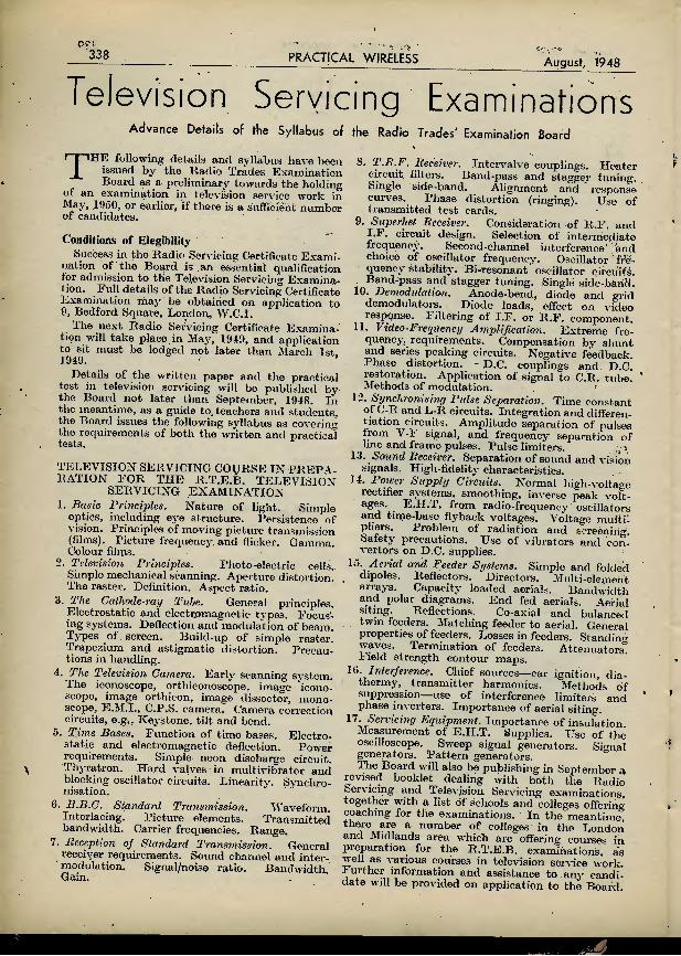
338 PRACTICAL WIRELESS August, 1948
Television Servicing Examinations
Advance Details of the Syllabus of the Radio Trades' Examination Board
THE following details arid syllabus have been issued by the Radio Trades Examination Board as a preliminary towards the holding
ot an examination in television service work in May, .1950, or earlier, if there is a suffieient number of candidates.
Conditions of Elegibility Success in the Radio Servicing Certificate Exami-
nation of the Board is an essential qualification lor admission to the Television Servicing Examina- tion. hull details of the Radio Servicing Certificate Examination may be obtained on application to 9, Bedford Square, London, W.C.I.
The next Radio Servicing Certificate Examina- tion will take place in May, 1949, and application to sit must bo lodged not later than March 1st, 1949.
Details of the written paper and the practical tost in television servicing will be published by the Board not later than September, 1948. In the meantime, as a guide to. teachers and students, the Board issues the following syllabus as covering the requirements of both the'written and practical tests.
TELEVISION SERVICING COIJRSE IN PREPA- RATION EOR THE R.T.E.B. TELEVISION
SERVICING EXAMI NATION 1. Basic Principles. Nature of light. Simple
optics, including eye structure. Persistence of vision. Principles of moving picture transmission (films). Picture frequency, and flicker. Gamma. Colour films.
2. Television Principles. Photo-electric cells. Simple mechanical scanning. Aperture distortion. The raster. Definition. Aspect ratio.
3. The Cathode-ray Tube. General principles. Electrostatic and electromagnetic types. Foeus'- jng systems. Deflection and modulation of beam. Types of screen. Build-up of simple raster. Trapezium and astigmatic distortion. Precau- tions in handling.
4. The Television Camera. Early scanning system. The iconoscope, orthiconoscope, image icono- scope, image orthicon, image dissector, mono- scope, E.M.I., C.P.S. camera. Camera correction circuits, e.g., Keystone, tilt and bend.
5. Time Bases. Function of time bases. Electro- static and electromagnetic deflection. Power requirements. Simple neon discharge circuit. Thyratron. Hard valves in multivibrator and blocking oscillator circuits. Linearitv. Synchro- nisation.
6. B.B.C. Standard Transmission. Waveform. Interlacing. Picture elements. Transmitted bandwidth. Carrier frequencies. Range,
7. Reception of Standard Transmission. General receiver requirements. Sound channel and inter- modulation. Signal/noise ratio. Bandwidth. Gain.
8. T.R.F. Receiver. Intervalve couplings. Heater circuit, filters. Band-pass and stagger tuning. Single side-band. Alignment and response curves. Phase distortion (ringing). Use of transmitted test cards.
9. Superhet Receiver. Consideration of R.F. and I.F. circuit design. Selection of intermediate frequency. Second-channel interference' and choice of oscillator frequency. Oscillator fre- quency stability. Bi-resonant oscillator circuits. Band-pass and stagger tuning. Single side-baflH.
10. Demodulation. Anode-bend, diode and grid demodulators. Diode loads, effect on video response. Filtering of I.F. or R.F. component.
11. Video-Frequency Amplification. Extreme fre- quency, requirements. Compensation by shunt and series peaking circuits. Negative feedback. Phase distortion. D.C. couplings and D.C. restoration. Application of signal to C.R. tube. " Methods of modulation.
12. Synchronising Pulse Separation. Time constant of C-R and L-R circuits. Integration and differen- tiation circuits. Amplitude separation of pulses from V-F signal, and frequency separation of line and frame pulses. Pulse limiters.
d. Sound Receiver. Separation of sound and vision signals. High-fidelity characteristics.
14. Pou-er Supply Circuits. Normal high-voltage rectifier systems, smoothing, inverse peak volt- ages. E.H.T. from radio-frequency oscillators and time-base flyback voltages. Voltage multi- pliers. Problem of radiation and screening. Safety precautions. Use of vibrators and con- vertors on D.C. supplies.
15. Aerial and Feeder Systems. Simple and folded dipoles. Reflectors. Directors. Multi-element arrays. Capacity loaded aerials. Bandwidth and polar diagrams. End fed aerials. Aerial siting Reflections. Co-axial and balanced twin feeders. Matching feeder to aerial. General properties of feeders. Losses in feeders. Standing waves. Termination of feeders. Attenuators) Field strength contour maps.
10. Interference. Chief sources—car ignition, dia- thermy, transmitter harmonics. Methods of suppression—use of interference limiters and phase inverters. Importance of aerial siting.
11. Servicing Equipment. Importance of insulation Measurement of E.H.T. Supplies. Use of the oscilloscope. Sweep signal generators. Signal generators. Pattern generators. The Board will also be publishing in September a
revised booklet dealing with both the Radio Servicing- and Television Servicing examinations, together with a list of schools and colleges offeriiT coaching for the examinations. In the meantime, there are a number of colleges in the London and Midlands area which are offering courses in preparation for the R.T.E.B. examinations, as well as various courses in television service work Further information and assistance to anv candi- date will be provided on application to the Board.

August, 1948 PRACTICAL WIRELESS 339
Modulation-1
In This Article H. REES, A.M.I.E.E., Discusses Some Further Technical Topics
WHAT do we really mean by amplitude modulation ?
In case this should be thought too easy a question, look at Fig. 1(a) and (b). One is a true amplitude-modulated wave. So is the other, in a sense. How would you explain the difference ?
What would be the result of extracting the modulation in the two cases and listening in on a pair of telephones or loudspeaker ?
We learn that an H.F. carrier is modulated by speech or music at transmitters; that the resultant complex wave is picked up and amplified ip.a distant receiver; that a rectifying device is
(a) pjg_ i_—Two different kinds of "amplitude modulation" in one of which there is a 180 deg. phase-reversal of the envelope, with consequent severe distortion and frequency-doubling {if the wave were rectified as
it stands).
essential to give rise to currents at modulation frequencies.
Which is all fairly straightforward. A rectifier (or " non-linear device ") generates an average D.C. when an alternating voltage of constant amplitude is applied, Fig. 2(a). If modulated, the rectified current component will be varying sinusoidally as in 2(b). A rectifier develops the " A.F. component," since it gives a current which is proportional to the ampli- tude of each R.F. cycle.
heterodyne (=beat) principle. It must embody an effect equivalent to detection to give us a current at beat frequency. It has a certain inherent non- linear characteristic, whereby "beating" and "■ detecting " take place at the same time.
In older circuits the incoming and local oscillations were heterodyned in a tuned circuit and afterwards rectified. For example, though adjustments would be difficult, the oscillator-detector of Fig. 3 might be modified for superheterodyne purposes.
But it seems we must not now .speak of " detect- ing." The modern mixer, it is suggested, is a unique non-linear device, which produces the
beat-difference by modulation; we learn the beat frequency is a " sideband " of the same kind as generated at transmitters when audio and radio frequen- cies are combined.
Established heterodyne princi- ples, with the necessity for rectifying, or its equivalent, are not mentioned. The B.S. Gloss- ary deprecates the use of the word " detection."
True, there is no particular virtue about this word, whilst the modern mixer is not a " rectifier " in the accepted sense. But it has non-linear pro- perties, and whether or not it is being used as a form of detector
or modulator, I will leave technical readers to decide.
About Non-linear Devices A non-linear element may be employed to modu-
late—if we start with frequencies in the radio, and audio, range. Thus the H.F. generated in an oscillator could be modulated by speech or music, when H.F. sidebands would result.
-_1_
Currert
Modulation or Detection? But to show the uncertainties
in using the word " modu- lation " consider next the frequency-changer of a modern superheterodyne.
Two frequencies are "mixed" to give a beat resultant. One time 'we kept to well-established principles by saying a first detector was essential to create a separate current at the beat frequency—a "beat" is itself of the nature of a modulated current. Fig. 1(a), needing rectification to extract the envelope.
These fundamental ideas have not changed. A modern mixer still works on the
tncresse //< "Mean 0,0."
(- O.Cr Component)
\
Current [/drying DC or AF Componeni
Voltage
Unsymmetr/cal Current
Symmetries! Alternating Voltage
IT"
Voltage
Modulated Applied Voltage
Fig. 2.—Use of a non-linear voltagejcurrent characteristic for rectification, i.e., detection. In modulating, the problem is reversed; a non-linear or asymmetric characteristic is employed to combine H.F. and
A.F. components in a manner to develop amplitude modulation.

340 PRACTICAL WIRELESS The same non-linear device may be used to
rectify, or detect. That should be its proper function in extracting a beat envelope, whether as orthodox first detector or modern mixer.
Because " non-linear " and " modulation " are taken to denote the same thing we are apt to con- clude : " Every non-linear device is a modulator." The generalisation should be : " Every non-linear device may he used for modulating or detecting."
August, 1948
V
7k
HF. Bypass
P'g- 3-—A simple self-oscillating detector which may be used to "beat" local and incoming oscillations to produce an audible note in a pair of telephones via an amplifier and A.F. transformer T, if necessary. Though difficult to adjust, the H.F. bypass condenser may be removed, arid an I.F. transformer substituted for T, giving the equivalent of early frequency-changers. An improvement would be to separate the " detector " and " oscillator " functions by using separate valves,
or multi-electrode types. If we heterodyne two volt-
ages to give an amplitude variation at their differences frequency, we plainly need the equivalent of a detector to extract the beat - difference. The latter is a form of modu- lation, quite true, but not of a kind which depends upon the action of any non-linear device, whilst the resultant frequencies generated are certainly not sidebands."
la=16, the current falling to zero for an instant at the peak of the negative half-cycle. At the positi\'e peak the total current becomes, for an instant, (Io-f-Ia) = 2Io, if Ia=Io.
It is then easy to see from the power expressions that the total power when modulating represents a 50 per cent, increase on the D.C. power, or : Total Power=1.5 X D.C. Power.
If we had an A.C. ammeter in the circuit it would register, first, lo. At 100 per cent, modulation the reading would increase to y/l.o X Io=1.225Io—a 22.5 per cent, increase on the D.C. reading.
Now, these are precisely the power and current ratios for a 100 per cent, modulated H.F. carrier; 50 per cent, more power must be supplied for modulating, whilst an H.F. ammeter will show a 22.5 per cent, current increase (as long as the modulation is a perfect sine wave).
Thus Fig. 4(b) does provide a useful method of showing how these figures are arrived at. It helps to dispose, too, of a few difficulties, such as why the ammeter registers 1.225Io, and not. (Io + 0.707Ia). . R.M.S. readings represent average power. In
each case—Fig.4(b) and modulated H.F.—the peak power goes up. four times, but the mean power increases by otiiy 50 per cent.—a current increase of 22.5 per cent.
The " Principle of Superposition " While 4(b) is a fairly accurate D.C./A.C. analogy
Mic Rec.
Bait.
r
A D.C. " Carrier '
fa) Pig- 4-—Simple " D.C. Modulation," i.e., modulation of a steady D.C., lo, by speech currents in an ordinary telephone line. The power ratios and r.m.s. current values in (b) are exactly the same as for a too per cent,
modulated high-frequency carrier. A good starting-point from which to discuss A.M.
is to consider a " zero frequency " or D.C. carrier. A common illustration is a simple telephone
circuit, Fig. 4(a). Speech alters the resistance of the carbon microphone, causing the line current to vary as in 4(b), for a single sinusoidal " tone."
We may call this modulation, although there are obvious differences to what we get on modulating an H.F. carrier, Fig. 1(b).
But 4(b) does bear a close resemblance to modulated H.F. in other ways. If this current were passed through a resistance R ohms, the unmodulated D.C. Power = IjR watts.
t\ hen modulated, the total power becomes, (D.C. Power -|- A.C Power)=IoR-f I■ ifjt
=(Io-fi'Ia)B, where, Ia = the amplitude of the A.C. portion, 4(b).
At 100 per cent, modulation," as in 4(b),
of a modulated wave, it is, in another sense, a case of " simple superposition."
We must be quite clear about this term. The Principle of Superposition, in physics, states that a number of frequencies may be superimposed to give a complex resultant waveform, but that each sine leave malting vp-the resultant remains entirely separate. As long as the circuit is "linear," there can be no modulation, though it is possible for frequencies within certain limits to " beat."
(To be continued).
WATCH YOUR DUSTBIN Waste Paper, Cartons, Cardboard, should be kept separate, dry and clean
for salvage.

August, 1948 PRACTICAL WIRELESS 341 SUPEKK COMMERCIAL three-band horizontal dial in cream and brown, lOin. xiiin.. with 4in. drum. Completely assembled on sub-chassis, ready to fit. 22/6. Modern style
•ilr square dial in Brown, Green, Blue on Cream, complete wor^h doubleri7^6POinter sp^in8:• etc- : very strongly made, *'F:T-S' 465 kc/s, permeability' tuned high " Q," small size, tested, per pair, 14/6. COMMERCIAL steel chassis punched for mains transformer i.r .s. smoothing, controls, tuning condenser ; fitted 5 amp. 2?oofedaflnish. l2r/6. A,E*/P-U- strip' stron= steel feet' rust-
,9fffra—Chassis complete with I.F.s. large dial. PoPtage1?,^ extra * 1110111(163 a t,ested circuit blueprint. Coil Packs. L.. M. and S., 33/- : 10-100 m.. 160 pf. type. 33/- :
W1Ah sta8"ei 50/" : Coils, superhet, 2/9 : pair ^Amplifiers, 8-24 watts, from £9/9/-. Clearance of resistors, condensers, electrolytics. " value stamP only- Trade supplied. C.O.D. service any MIDLAND RADIO COIL PRODUCTS
19, Newcomen Road, Wellingborough
j RADIO-CRAFT LIBRARY j j 1 Radio Test Instruments. = Radio-electronics Circuits. I Advanced Service Technique, i Amateur Radio Builder's Guide.
Elementary Radio Servicing, B Radio Questions and Answers.
Handy Kinks' and Short Cuts. 3/6 each. Plus 2d. postage. j
j' We have the finest selection of British and j I American radio hooks. Complete list on i
application. i —
THE MODERN BOOK CO., ; (Dept. P6), 19-23, Praed Street, London, W.2. !
ill METEOR
ELECTRONICS Gloucester Row,
Weymouth.
METEOR 2 WAVE COILS.
TRF & SUPERHET IB2T and IB2S
/I TYPE FOR NEW MIDGET 375 PF TUNING
CONDENSER
Price 7/6 Pair
MKJBi Pf ATTW/if Order with confidence. Full satisfaction assured. SPECIAL OFFERS
"p4°PI5Td!rSsad and Jack Plu='5/-rair <boxea
2/1^3 CORD.—.3 amp. 60 ohms per ft., 2-way. 1/6 yd. ; 3-way, 1™isNtand£dN"eNSERS^-0005 P0LAE MIDGET' 11/6- CONIJENS'JnS—.ooa, m doz. .006, 3/- doz. .1, .0] 9'- doz /oOO^v.^canned, 8.6. 8 mfd./350v. midgets, 3/-. 8 mfd.','450v., SPEAKHRS.—P.M. (less trans.). Sin.. J2/e : Sin 84;- ■ Limited quantity Sin. TRUVOX P.M SPEAKERS IBB Trans, to match, S/6. Multl Ratio Do.. 7,6. VOL. CONTROLS.—All values (Centraiab). L/S, 3/6 : W/S 4 9
CISZi
Postage Extra. LARGEST ASSORT- MENT OF VALVES ALWAYS IN STOCK. IB M 7 ' R IPS Kl let us - - -r Min 1 Kingston 8353 YOUR ENQUIRIES. 39, castle Street, Klneston-on-Thame
"" ■ Siurrey.
COVENTRY RADIO COMPONENT SPECIALISTS SINCE 1925
STOCKTAKING Lowest prices in the Trade. Send Id. for our Clearance List of New Radio Components. No rubbish. Examples : New 8 mfd. 450^volt Electrolytic Condensers (1st grade), 2/11 New 8-8 mfd. 450-volt Electrolytic Condensers (1st grade)', 4/9 Tubular .1 mfd. 350-volt 1st Grade Condensers, per doz., 4/6
NOTE.—Our General Catalogue of 2,000 components will be ready in August. May we reserve you a copy ?
COVENTRY RAD IO DUNSTABLE ROAD, LUTON, BEDS.
M. & J, PEARSON, 373 Eglington St. Glasgow, C.5. Special Offers
CONDENSERS Block type .1 plus .1 mfd.. 3,000 volt, 2 6 each ; 800 mfd., 12 volt, 21- each ; 8 mfd. G.E.C., 600 volt, in boxes of two. 6/6 box ; 4 mfd., 1.500 volt. 4 - each ; 4 mfd., 450 volt. 2 6 each. ELECTROLYTICS 4 mfd., 450 volt, metal. 25 mfd., 25 volt, cardboard, 75 mfd.. 50 volt. Bakelite, all 10/- half dozen : £4 10s. half gross. £8 per gross. These will be mixed as ordered, TUBULAR—.1 .350 volt, 5/- doz., 20/- per half gross, 35/- per gross : .1 mfd., 1.000 volt. 9'- doz. ; .25 mfd., 350 volt.
5/- doz. ;.l mfd.. 450 volt. 8/6 doz. METERS
FERRANTI—0-500 micro- ammeters, grade 1, moving coil, 2-1 in. flush mounting, new and boxed. 16 6 each. 0-100 micro-ammeters. 21 in. flush mounting, calibrated 0-1,500 yds., new and boxed, 20/- each. 0-300 volts A.C.. 24in. flush, moving iron type, new and boxed. 8/6 each. : We pay all Carriage (Gt. Britain only) and Cash With Order Please. No Lists issued).
NEW! PRESS-BUTTON COIL PACK
I S8/3
Trade enquiries invited
The famous 30 Coil Pack now designed for press - button switching. THE P.B.30 PACK COIL 4 Buttons select 3 wavebands plus Gram. Bugh " Q " coils in Superhet circuit, 465 kc/s. I.F. Fully aligned and gain tested. Pick-up can be permanently connected. Size 4in. x 4in. x Uln. deep. NO PURCHASE TAX.
Send stamp for latest list P.l London Television Co. Ltd.. 694. Lea Bridge Road. London, E.10-
i Phone : Ley 4380
Short-Wave Equipment Noted for over 15 years for . .
Short-Wave Receivers and Kits of quality One Valve Kit, Model " C " .. ' Price 20/- Two " .. "E" ... „ 43/. These kits are complete with all components accessories, and full instructions. Before ordering send stamped, addressed envelope for descriptive catalogue. Note new sole address :—
" H.A.C." SHORT-WAVE PRODUCTS (Dept. TH) 66 New Bond Street, London, W.l

342 PRACTICAL WIRELESS
RADIO imu:- X VALVES ?46JIIGHST:flft(liisie*W5
Invmnir you to Incorporato your name on our.liar^ain IMailln^ l.ist. This has eonsiilerahly ki-ouji since last year, and 11" not yet on it. please send name & address in hlock letters and mark ' NAMF. ADDRESS
August, 1948
BRIM \R.—R2. R3. 5Y3, 5U4. 80. 5Z3. 5Z4, 6X5, 5V4. ID5. 25Z4. ID6. 0Z4. 35Z4. 15DI. 15D2. 9D2. 8D2. 10D1. 11D3. 11 Do. 703. 4D1. C 'OSSOR.—442BU, 43IU. 4THA. 41STH. MVSPenB. MSPen. MSPenB. DDL4. DDT. 41MTD, 41MHL. 41MP. MPPen. PT41. 2P. 41 MX P. 202STH. 13 VP A. 13SPA. 202DDT. 210 VP A. 210HF. 210DDT. 213P. 240QP. 215SC1. 2I0LF, 4TSP. 4TSA, 202VPB, OM4. OM6. OMIO. M AIU OM OSRAM.—U10. U14. MU14. U18/20, U30. U52. U31, U74. U7G. X41. VMP4G. MS4B. MSP4. KTZ41. D41. MH4. MH41, 1VIL4. MKT4. KT41. PX4, DA30, VMS4B, H30. X63. X65. KTW63. KTZ63. KTW61. D63, 1163. 1-63, DH63. DLt>3. KT63. KT66. KT61. X63. KT71. X61M. KrI74. X64. KT33C. X24. Z22. HD24, TjP2, KT2. P2. QP21. Z14. N16. - D42. U16, U17. GT1C, GU50, KT44, Z62. ZG6. UI9 23. MAZDA.—UU6. ACTHl. V9I4, AGP. ACoPenDD. HL41. HL41DD. VP41. I'll. T41. DDI I. HL42DD. VP1322. PenDD4030. TH2321. VP133. Pen453DD, HL133DD, QP230. TP26. Pen 2.3. QP25. T1'22. TP25. DD207. HI,23. HL23DD. VP23. SP2220. SP42. U22. ACP4. Ml FEARD. — DW2. /DW4'350. IW4 350 DW4/500. l W4r,00. FW4 500. AZ1. AZ31. UE3C. TH4B. FC4. VP4. VP4A. VP4B. SP4. 2D4A. TDD4. 354V. TT4. PM24.M, Pen 4DD. PeilB4. AC044, D024. Petl428. TH2IC. TH30C. FC13, VP13C. SP13C. 2D13C. TDD13C, HL13C. VP13A. SP13. Pen36C. C[,4. Pen40DD. CCH35, DAF91. DF51. DF.91, DK91. DL92. EA50. EBC3. EBC33. ECC31. ECC34. ECH21. ECH33. ECH35, EF9. EF22. EF36. EF37. EF39. EF50. EF54. EK32. EL2. EL3, EL32. EL33, El,35. EL37. ED38. EMI. EM4, EM34, VP2B. SP2. PM12Mv FC2. FC2A. DK32. DAC32. CL33, CBL1. CBL31, EBL21. UBL21. UY21. I'll 11.IPS.—1821. CY31. C1C, Cl. CY1. .TUMiSKA M.—LD210. HP220. LL4. APP4C, APP4G. APV4, EZ4. 2AG. 2A7. 2B7. GA7. - GB8. GOG. GDG. VP13K. PPa5. HL13. 6AC7. 12C8. 25YG, 25y5, HP410G. HP1018. HP4101, MH4105. 11 IN AC.—XL. XD. XY. XP. XSG, XH. xw. A VIERTCAN.—0Z4. 1A4. 1A5. 1B5. 1D7, 1LN5. ILCtf. 1S5, 1T4. 1T5. IV. 2A3. 2X2. 2AG. 2A7, 2B7. 3A8. 3S4. 3Q5. 5U4. 5V4. 5Y3. 5Z3, 5Z4. GAT 6A7. 6A8. 6AB7. 6AC7. 6AE5. 6AE6, 6B7. GB8. 6C4. 6C5. 6C6. GC8. GD5, GDG. GD8. 6E6. 6F6. 6F8. GG6. 6H6. 6J5. 6J6. 6K5. GK6. 6SG7. GSH7. 6SJ7. 6SK7. 6SL7. 6SN7. 6SQ7. GSR7. GSS7. 6V6. 6X5. GV5. 7A7. 7117. 7BG. 10, 12A5. 12A6. 12C8. 12J5. 12K7. 12K8. 12Q7, 12SA7. 12SF5. 12SK7. 12SL7. 12SQ7. 12SR7. 14A7/14B7. 14B6. 14Q7. 15. 17. 18 . 20. 22 . 25Z4 . 26 . 27 . 32, 34 . 35A5. 35L6. 35Z4, 35Z5, 37. 38. 41. 42. 43. 46. 48, 49. 50. 53. 55. 5G. 59. 71 A. 76 . 77, 78 , 79. 80. 83. 81. 89, 884 . 954 . 955. 956. 9001. 9002. 9003, 9004. 9005, 9006. and 101 more types. Order C.O.D. above listed numbers or equivalents (subject to stock). Please enquire for any valve you require, even if not listed. We may have it. Old and new types are arriving- daily. — STOP PRESS : COl.i,ARO. -Gram Motor and magnetic Pick-uo with auto-start and stop and speed Regulator AC100 250v. 12in. turntable £9.13-6. TR i PFETT.—("American) volt-ohm-mill, ammeter £12.12'.0.
Please write immediately to (P.W.)
1 RADIO m N MS VALVES 1
The " Fluxite Quins " at Work "Just horrible howls in the night.
There's spooks in that manor all right."
Cried EH " Oh dear no. That's a dud radio,
Watch FLUXITE soon put 'em to flight! '*
See that FLUXITE is always by you—in the house—garage — workshop — wherever speedy soldering is needed. Used for over 40 years in government works and by the leading engineers and manufacturers. Of all ironmongers — in tins*
I0d., 1/6 and 3/-.
To CYCLISTS : For stronger wheels that will remain round and true, there's a time tested tip. Tie the spokes where they cross with fine wire one/ SOLDER. It's simple — with FLUXITE —
but IMPORTANT.
The FLUXITE GUN puts FLUXITE where you want it by a simple pressure. Price 1/6, or filled, 2/6.
ALL MECHANICS W/U AVE
FLUXITE IT SIMPLIFIES ALL SOLDERING
Write for Book on the ART OF " SOFT " SOLDERING and for leaflets on CASE~ HARDENING STEEL and TEMPERING TOOLS with FLUXITE, also on " WIPED
O/NTS." Price Id. EACH. FLUXITE LTD. (DEPT. W.P.),
BERMONDSEY ST., S.E.I
GALP1 N S ELECTRICAL STORES
408, HIGH STREET, LEWISHAH, LONDON, S.E.I3
'Phone : LEE GREEN 0309 Terms : Cash with order. (No C.O.D.)
MAINS TRANSFORMERS, as new. input 230 volts, 50 cycles, output, 12 volts, at 8.1 amps., A.R.P. shelter transformers, 25/- each, post 2/-.
Ex-R.A.F. MICROPHONE TESTERS (new). These consist of a Ferranti 0 to 450 M/amp., 2.1-in. scale meter shunted to a I M/A incorporated Westinghouse Rectifier, the whole encased in polished teak case, calibrated at present 0 to 10 volts, 32/6 each.
Ex-Government (new) MAINS TRANSFORMERS, 200/250 volts, 50 cycles, l-phase input, 525/0/525 volts. 150 M/amps., 6-3 volts, 5 amps. 5 volts 3 amps, output, standard rating. 35/- each, post 21-. Mains Smoothing Chokes. 10 Hy.. 150 Ml amps.,-180 ohms D.C. Res., 816; ditto, 100 M/amps.. 5/6 each, post 9d. All the above can be offered in large quantities. Please write for special quotation.
Ex-Government (GEC) ELECTRIC FANS, 12 volts, AC/DC laminated field, complete with Sin. impeller. New, boxed. 201- each, post II-. Transformer to suit, 230 volts, input 12/16 volts at 4 amps, out* put, 32/6 each.
MAINS VARIABLE RESISTANCES (slider type), new, ex-Govt., 14 ohms, carry I to 4 amps., graduated, useful as dimmers, etc.. 25/- each ; another. 0.4 ohms, carry 25 amps., 25/- each, post 1/6. Ex-Govt. Moving-coil Cell Testers. 3-0-3 volts (new), 25/- each.
MAINS TRANSFORMERS (Auto Wound). Voltage Changers tapped' 10. 20, 25. 90. 130, 150, 190, 210 and 230 volts, all at 1,000 watts, a combination of 34 voltages can be obtained from this transformer, new ex-Government Stock,' £5 10s. Od. each, carriage 5s. Mains Booster Transformer, tapped 0. 6, 10, 19,, 175, 200, 220, 225, 240 and 250 volts, at, 1.500 watts (new ex-Government), £5 5s. Od. each, carriage 51-. Another 200 volts input, 240 volts output at 2,500 watts. £7 10s. 0d., carriage 7/6. Another 2 to I ratio, I 10 volts input, 220 volts output, or vice versa, at 4,000 watts, £12 10s. 0d., carriage 10/-.' Another 230 volts input, tapped output' 40, 41, 42, 44, 46, 47, 49 and 52 volts af 100 amps., £15 0s. Od. each, carriage 10/-. the latter two are double wound. Another Auto Wound, tapped 0, I 10. 150, 190. 210 and 230 volts at 1,500 watts. £6 10s. Od. each, carriage SI-. Ditto. 2,000 watts, £7 5s. 0d., carriage 5/-.
MAINS TRANSFORMERS (new), input 200/250 volts. 50 cycles, l-phase, output 350/0/350 volts at 180 M/amps., 4v. 4a., C.T. 6.3v. 4a.. C.T. 5v. 3 a.. 37/6 each, post 1/6. Ditto 500/0/500 volts, 150 M/amps.. 4v. 4a., C.T. 5v. 3a., 47/6, post 1/6. Another , tapped 6, 12. and 24 volts at 10/12 amps., 45/- each, post 1/6. Auto-wound Voltage Changer Transformers, tapped 0, 110, 200, 220 and 240 volts, 250 watts, 45/- ; 350 watts, 55/- ; 500 watts, 70/- each, carriage 1/6. (Please note these transformers can be delivered ten days from receipt of order.)
Ex-GOVT. (as new) ALTERNATORS, 230/250- volts, D.C.. input 230 volts. 50 cycles, l-phase at .65 amps. ; output, separately excited, 24 volts at .4A. £5 0s. Od. each, carriage 7/6.
Ex-NAVAL (self-energised) TELE- PHONE HAND-SETS, 10/6 each, post I/-, or Complete Telephones. Magneto Ringing and Neon Light, at 35/- each, post 2/6.
CONTROLLER ELECTRIC PUSH- BUTTON UNITS, five press switches and master dewar switch, complete, brand new (useful for all model work, telephones and remote control), 51- each, post 9d.

August, 1948 PRACTICAL WIRELESS "S43
Programme Pointers
" An Eiysian Referendum" is Discussed Here by MAURICE REEVE SOME time ago, I. discussed the praetfcability,
or otherwise, of holding a plebiscite in order to get to the bottom of the public's real
wishes concerning their radio listening. So far as the B.B.C. is concerned, it does a wonderfully good job, mainly, I suppose, by deduction based on its mail bags.' This leads to results which are, by and large, satisfactory, but can never be wholly satis- factory. Something of the nature of a Gallup Poll, or a referendum based on the widest possible franchise, and at regular intervals, is necessary
rapturous exaltation in keeping with a beleaguered garrison about to be relieved, filled the countenances of the true artists present. Only the easy money merchants yet continued to wear their furrowed brows and clenched teeth. For the first work to gain a vote was Elgar's Piano Concerto. It was ijimoured that Elgar had written with as great a mastery and insight for that instrument as he had for the violin in his incomparable violin concerto. The solo part was not only as rich in harmonic and contrapuntal devices as any other
fn .order to claim that we are being given exactly . master concerto—or as Elgar at his best anywhere what we want. Otherwise, we might as well elect a Government from newspaper editors' postbags and party canvassers. This might, on those occasions when the wishes of the people are obvious-to all, produce a representative Govermnent within narrow and circumscribed limits. But nothing more.
I was imagining myself being present the other day at the counting of such' a ballot on the most popular in broadcast symphony concert programmes. The result was not only staggering, but cataclysmic. L was completely bowled over. Entirely new vistas and horizons were opened up as the names of the works voted for were recorded, with tens of thousands of votes against each title. Almost the entire classical repertory, as we have known it since broadcasting began and for long before that, was " conspicuous by its absence." Gone were the major portion of the symphonies and concertos that our " Tschaikowsky-soaked population " have saturated in for so long; neither he nor Rachmaninoff gained a single vote. The only Beethoven to collect a few were the sixth and seventh symphonies and the fourth piano concerto. Mozart was fairly well supported, though nothing like so heavily as one would have expected. Schubert had vanished, so had Ravel, though a little Debussy seemed likely to receive a welcome. The rout of the old gang was so complete that even the ranks of Tuscany forbore to cheer.
Many famous musicians were present at the " count." Composers were deeply anxious as to the fate of their works in the public estimation. Executants were apprehensive about their reper- toires—the results of lives of technical toil and physical and mental labour. Even impressarios were there, waiting for the news first hand and without trimmings. One eminent pianist and a famous conductor, who arrived together, stood aghast as the results of their life's work, which, incidentally, had brought them a considerable amount of both artistic and material reward, seemed as if it were being thrown into the waste- paper basket. The agents felt that all their contracts with artists, covering more than the two coming years, would have to be scrapped. ~ Everything was chaos, as after the crash of defeated dynasties in a world conflagration.
Elgar's Piano Concerto But when it was known what the public had
voted for .in place of their former favourites, surprised wonder, delighted anticipation, and
—but it was extremely brilliant, dazzlingly difficult, and altogether " grateful " for the vainest of pianists.
Then came votes for concertos by Dvorak and Sibelius, also for the piano. Tschaikowsky beaten at his own game ! The new look in concertos. " They'll never want to hear the B flat minor again," audibly commented the popular pianist, to which his conductor friend was heard to reply ; "It should suit you down to the ground; you'll tear its passion to tatters."
Wagner Symphony Next was a symphony in C major by Wagner,
shortly, followed by a second in E major. The slow movement of the latter was stated to be even longer and more beautiful than the " Siegfried Idyll." Other works which the public had been pleased to smile its favours on were a violin concerto by Berlioz—as diabolic as Paganini but much more brilliant musically—an Elgar arrangement for orchestra of Bach's St. Anne's Organ Prelude and Fugue, a piano concerto by Cesaf Franck and one by Granados, symphonies by Richard Strauss, Faure and Rimsky-Korsakov, as well as numerous concert pieces by this one and that.
And so the revolution was over. The great question now was, would the concert-going public get what it had voted for in such an overwhelming manner '? Votes of thanks were passed, and suitable speeches made, to those who had so ably conducted the proceedings, the captains and the kings departed and heads were bent over future plans. How long would the mastering and perfecting of all these great works take—that is, if the pianists fulfilled their contracts to play the B flat minor forty-seven times in the next six months and the conductors their Pathetiques, etc., an equally colossal number ? One artist, whose famous performance of the former work in recent seasons was known to run well into three figures, said he would be quite willing—and thought he would be quite able—to fulfil his commitments to that work in the immediate future .without rehearsal, so as to give some time daily to " learning up " the new Dvorak. He was tickled to death at the prospect of regaling Promenade audiences with new lush melodies and exotic rhythms comparable if not superior to those in the "New World" and other Dvorak symphonies.
Meanwhile the agents went frantically to work booking up their artists to play these new or, about

344
to become old, favourites, and substituting, wherever possible, Sibelius for Rachmaninoff, Cesar Franck for Beethoven and Wagner for Tschaikowsky. Everything now seemed set fo{ another concert boom comparable to the Tschaikowsky and neo-Tschaikowsky boom of the war and immediate post-war years. At last the public would be given what it wanted, and not what was surmised as its wants. It would soon be seen how it had been enduring what had been foisted on it.
But, alas! it was only a dream—or, rather, wishful thinking. On my way home my Ko. 9
August, 1948 bus halted at the Albert Hall, and an amusingly facetious conductor called out "Albert 'All. Anyone want n nice bit o' music. Don't think much on it meself." As .1 looked out of the. window at the concert poster immediately in front of me the first item on it that hit me in the eye was :
" Concerto No. I in B flat minor for Piano and Orchestra. Tschaikowsky."
I didn't trouble to look for the pianist's name. Moral : the only works that can ever take the
places of those now considered hackneyed and overdone have not yet been written !
PRACTICAL WIRELESS
News from the Clubs
THE WEST MIDDLESEX AMATEUR RADIO CLUB Hon. Sec. : ('. Alabaster, 34, Lothian Avenue, Hayes, Middlesex. '"pHE above club continues to be extremely active and pro-
-*■ jrressivc in all spheres, and membership increases steadilv. Heccut meetings have been devoted to a junk sale, and a very timely lecture ami discussion conducted by Mr. Bostock (G3BW(j) on battery portable equipment.
The club is still seeking a suitable club room where a work- ■ shop ami permanent equipment can be set up. Plans for the club transmitter are well in baud, and the transmitting licence is awaited.
Meetings continue to be held on the second and fourth Wednes- days of every month at 7.:!0 p.m.. at the Labour Club Booing Vxbridge Boad, Sduthall, Middlesex. SOUTHAMPTON RADIO CLUB Hon. Sec. : John H. Sillciu-e, 80, The Drove, Coxford, Southamp-
ton. AT a meeting of the above club held recently, at the " Anchor
Stores," East Street, Southampton. Mr. Bobert Emmett offered the use of his own workshop and shack for future meetings of the club. j
Jt was decided at the meeting to accept Mr. Emmetrs*offer, and Mr. Silleucc (secretary), in thanking him on behalf of the members of the club, said that it would allow the club to expand its activities, as the present accommodation, although suitable for talks, lee tares, etc., did not allow for any practical or experi- mental work to be carried out.
It was decided to hold meetings at the new club room weekly until further notice. All meetings will be held at 7.30. p.m'., with Morse practice' until 8 p.m. Prospective members are invited to attend meetings, or write for particulars of the club's activities to the secretary of the club, BASINGSTOK E-DI STRICT AMATEUR RADIO SOCIETY Hon. Sec. : L. S. Adams (BSWLSOof " Boslen," J(>, Bramblys
Drive, Basiugstoke, Hants. A SEBIES of lectures, one per month, will be given by member .). A. Lowe on the "Oscilloscope and ils Applications."
at the Cricketer's Jim Hall, May Street, A.C. being available. ROMFORD AND DISTRICT AMATEUR RADIO SOCIETY Chairman ; D. Coppendale, c/o o, Morden Boad. Chadwell
1 tea th, Essex. rT",HE club transmitter is nearly ready to go on the " air " and will bo operated from the H.Q. on 3(»6 metres, although it
will be able to operate on the 8!i and 40 metre bauds. Any reports from listeners will be Welcomed and will be replied to with a QSL card.
The following are forthcoming fixtures: 'July 13(h. Workshop evening. July 20th. • " Top band portable TX and BX field evening. July 27th. Workshop evening and discussion on above field
evening. August, ofd. Sale of members' surplus gear. August 101 h. Workshop evening. August 17th. Five-metre field evening, August 24th. Lecture. August 31st. Field exercise to be arranged later. September 7th. Sale of members' surplus gear. September 14th. Lecture and Demonstration—" Television," by Mr. J. Erskin. September 21st. Workshop evening. September 2Sth. Lecture—" Transformer Design," by Mr. J. Erskin. October 5th. Sale of members' gnrpttis gear. '
October 12th. Workshop evening. October 10th. Lecture—"Noise Suppression," by Mr. J.
Erskin. October 20th. Workshop evening. T
KINGSTON AND DISTRICT AMATEUR RADIO SOCIETY Hon. Sec. : A. W. Knight ((J2LP), 132, Elgar Avenue, Surbitomv
Surrey. (Telephone: ELM 0031) T-'HE society endeavours to eater for all classes of radio'
-*■ enthusiasts. A series of interesting lectures has been! arranged for Fridays—started in June. The club meets, alternate Thursdays, at 7.30 p.m., at the Kingston Hotel.' Visitors and new members are cordially invited. ' . STOKE-ON-TRENT AMATEUR RADIO SOCIETY ll Hon. Sec. : D. Boole (G.3AQW), 13, Oldficld Avenue, Xorton-Ie--
Moors. Stoke-on-Trent, Staffs. WfEEKLV meetings are still in progress for the members of ^ the Stoke-on-Trent Amateur Radio Soeietv, at their
H.Q. in the Tabernacle Hall. High Street, Hauler. u: There has been much act ivity recently, lecturesby (he Chair-" man (G3CD) on Speech Amplifiers: Converters, bv Mr. X'.
Boberts (Treasurer), who has just had the " pleasure ""of sittihg*' for the R.A.E..and " Radio Receivers through (he Ages," by a. real old timer, G2WN, Mr. Wilson, whose "ticket" dates back, to 1010. 2WN told the story of the time when lie purchased a hand-driven generator and employed his XV Land four daughters to turn the handle in relays, for a consideration. READING AND DISTRICT AMATEUR RADIO SOCIETY Hon. Sec. ; Alex Mercer, 23. Oakley Boad. Caversham, Beading. AT a recent meeting of the above society, the subject of the'; ^ demonstration was specially for those new to transmission,-
and also the "hopefuls." Mr. G. Guy (G8TH), using a small 5 metre Tx., demonstrated methods of matching aerial input impedance, to that of the feeder line. At the same time the ' importance of correctly loading flic output of the, transmitter to obtain good power efficiency was shown. It is hoped to have a similar demonstration-on neutralising from Mr. Guy later in the year.
Later, Mr. F. Buddie talked on the problem of obtaining ade- quate selectivity, without losing completely the intelligibilifv of the signals. A double superhet of about IDoo vintage, giving single side-band reception of either sideband, with a band width of about 4 kc/s was described. Finally, " A Lazy Man's Q,5er," a method of obtaining the necessary selectivity by inserting the Bt'453 between the I.E. and detector stages of a communications receiver, was demonstrated.
Meetings are held at Palmer Hall, West Street, Beading, on the second and last Saturday of the moiith. WALWORTH MEN'S INSTITUTE RADIO CLUB Hon. Sec. : B. E. Symons, 100, East Dulwich Grove, Dulwicb
S.E.22. A MEETING of the club took place recently in order to finalise the rules and constitution of the club.
Owing to pressure of business the Secretary (Mr. P. Senechal) regretfully tendered his resignation, and in his stead Mr. B. E. Symons was elected.' Membership has increased considerably since the club was inaugurated and it is hoped that good progress will he made. Arrangements are being made with industrial concerns for the purpose of visits, and leetfiire-demonstr-atioris.
New members are still heartily invited and particulars may be obtained from the secretary.

August, 1948 PRACTICAL WIRELESS 345
Adopt Peter Pan
-~s<3 The latest addition to oua range of first-class KITS. Attractive A.C./D.C. 3 valve plus rect. med./long wave T.R.F. receiver with excellent performance and quality. • All components available from stock. 3, full-scale blueprints and full list of parts required. 3/6. Complete kit, 10 gas., plus P.T. Electric gram motors for A.C. mains. £4 19s. 6d. Full illustrated lists (2Jd. stamp) from
THE TELERADIO CO. IS7, Fore Street, London, N.I8.
HIGHSTONE UTILITIES Crystal Sets.—Our latest Model is a real radio receiver, which is fitted with a per- manent crystal detector. Why not have a set in your own room—9 6, post 6<i. De Luxe Receiver in polished oak cabinet, 18/6, post 1/-. Spare Permanent Detectors. 2/- each. When ordered separately, 2 6, post 3<l. Headphones, reconditioned and in good order', 5/6, post 6cl. (better quality. 7 6). New Headphones, 10/- a pair, post 6c!. Balanced armature type (very sensitive, and very suitable for use with crystal sets), 12/6 a pair, post 6d. New Single Earpieces, 3/6. Bal. armature type. 4 6 : ex-R.A.F. earpiece, 2/-, post 4d. Headphones with moving coil mike. 15/-. Similar phones with throat mikes. 12/6, post 8d. Headphone Cords, 1/3 a pair, post 3d. Replacenient Hands. 1/3, post 4d. Wire Hands, 6d. Hand Microphones, with switch in handle, and lead. 4/-. Similar instrument moving coil, 7 6, post 6d. Sparking Plug Neon Testers with vest pocket clip, 3/3, and with gauge. 3 6. post 3d. Telephone Sets, with ringing hand genera- tor, twin bells and G.P.O. type handcomb, 30/- each. carr. 2/6.. 57 6 pair. carr. 3 6. New handcomb sets. 7 6, post 6d. Telephone hand generator with handle, 9 6, post 1 6. Bell. 4/6, post 6d. Ex-R.A.F. 2-Valve (2-volt) Amplifiers, can be used to make up a deaf aid outfit, intercommunication system, or with crystal set. complete with valves, 20/-, post 1/6. Ditto, less valves, 10/-. Meters, All brand new. 0-1 m,a, 2in. m-c, 10/- : 3.5 amp., 2in., T.C., 7 - : 4 amp., 2iin. thermo coupled in case with switch, 7 6. 600 m/a., 3in., m/c, 15/- : Double reading 40/120 m/a, 2in., m/c, 8/- : 20 amp.. 2iin., m/i, 9 6 : 15 volt 2lin.. m/c. 9/6 : 30 amp., 6in.. m/i. Switchboard mounting, 35/- ; 6.000 v., 3Ain. m/c. 57 6. Post Extra. Money refunded if not completely satisfied.
HIGHSTONE UTILITIES, 58, New Wanstead, London, E.ll.
Letters only. New Illustrated List of above and other Lines enclosed with all orders on request, with Id. stamp.
SAMSONS
SURPLUS STORES THE V.F.O. YOU'VE BEEN WAITING
FOR ! ! MASTER OSCILLATOR, by R.C.A. Frequency range, 1-10 mc/s. Output sufficient to drive any p.a. Uses 807 valve in extremely stable circuit. Very accurate dial calibrations with unique dial mechanism. Metering of doubler or buffer stages grid current included. Housed in solid cast case, with shock absorber mountings. Supplied brand new with valve, accessories and operating manual. As from makers, £61101-, carriage SI-. No C.O.D. R.F. UNITS, TYPE 27. Range 60-80 mc/s. Ideal as converter for 58 mc/s when modified. Complete with valves, as follows : VRI36 R.F., VRI36 Mixer, VRI37 Osc., 2716, carriage II-. R.C.A. MAINS TRANSFORMERS. Primary, 190-250 v. A.C. Secondary, 2,000-0-2,OOOv. or 1,500-0-1.500. 1.75kVA. Price £61101-, carriage 7/6. No C.O.D. HEAVY DUTY CO-AXIAL CABLE. 30ft. lengths, 72 ohms impedance. With 2 female Pye connector plugs, 8/6, post paid. Male connector plugs, II- each extra.
169-171, Edgware Rd., W.2. Tel. : PAD 7851.
and 125, Tottenham Court Rd., W,
Tel. : EUS 4982. All orders and correspondence to Edgware
Rd. Branch, please.
rFOR HOME ^ CONSTRUCTOR '
We specialise in supplying complete kits and individual component parts for all circuits described in this journal.
PETO SCOTT. All Dry Portable 4-valve 2-waveband superhet in neat wooden cabinet finished in leatherette. Overall size lOin. x 121in. x 41in. Weight of receiver complete with batteries 14ilb. £15.18.8, or on H.P. TERMS Deposit £3.3.8 and 12 monthly payments of £1.4. POCKET VOLTMETER, moving coil' ranges 0/15 and 0/250 volts, D.C. (ex Service), 18 6. CHASSIS, PANELS, etc., made to your own specification. (Black Ripple, Plated or Natural Finish.) ALUMINIUM CHASSIS (22-gauge). Sin. x 6iin. x 2iin.. undrilled 5 -, drilled to own specification at extra cost. H.B.L. SUPER S.C;.3 BATTERY KIT, covering medium and long waves, complete kit of components, chassis, valves and full instructions. £5 15s. Circuit wiring diagram and component list for the H.B.L. l-valve, S.G.3, or S/W2 kits, price 1/-. Send 21 d. stamp for our Brochure of Kits, Components, etc. Also details of our Practical H o w-to-Bui I d-11 Books, com- plate instructions and designs for the HOME CONSTRUCTOR.
HEHBEST BROS.. LTD.. 26, Green Lanes, London, N.I3
Telephone ; BOWES PARK 6289.
H. P. RADIO SERVICES LID. OFFER
m
Brand New Ex-R.A.F. R1224? Battery Communication Receiver 5 Valve Superhet of the Highest Class. 3 Wavebands : 33-70 metres. 70-150 metres. 150-300 metres. Valves. 2/VP23's, FC2A, HL2, PM2A. all included. Has R.F. stage. Muir- head dials, two Output Jacks. Air Ministrv grey cabinet. 15ins. long. lOins. high, 9ins. deep. Requires Aerial, 12Gv. H.T., 2v. L.T.. 9v. G.B. and Loudspeaker or 'phones to put into immediate operation. All leads clearly marked. Designed specially for long distance high quality reception. We have such a high opinion of these receivers that we unhesitatingly GUARAN- TEE Satisfaction or Money Returned within 7 days. Price £5/10s. Carefully packed. Carriage Paid per Pass. Train. Instant Delivery. H.P. RADIO SERVICES LTD.
Britain's Leading Radio Mail Order House 55 County Rd., Walton, Liverpool, 4 Tel: Aintree 1445 » Estab. 1935
PRATT'S RADIO 1070, Harrow Road, London, N.W.10. (Nr. Scrubbs Lane.) 'Phone : LAD. 1734. AMPLIFIERS.—College AC10C, 10 watt. 4-valve mike stage, separate mike and 'gram inputs and faders. tone control, feedback. A.C. £8/18/6, with adaptor, etc.. for supplying L.T. and H.T. to feeder unit £9 18 6. Model AC.15.E. 15 watt, 6 valve, with P.Pull output stage. Feedback over 2 stages. Mike stage. Separate mike and 'gram inputs, with faders. tone control. Complete with metal amplifier case. Supplies H.T. and L.T. for radio feeder unit. A.C. £14/14/-. UIOE. 6 valve P.Pull amplifier for D.C./A.C. mains. Separate mike and 'gram inputs, mike stage, twin faders. Complete with case. £12/13/-. All match 3, 8, 15 ohm speakers. Amplifier list on request. SPECIAL OFFER.—3-valve, 5-watt ampli- fier. A.C., electric gramophone motor. B.T.H. pick-up. lOih. Goodman's speaker. Separate units. £14 19 6, inc. tax. Carriage 5/- extra. MISCELLANEOUS.—Wearite P. coils, 3/- each. Dual range coil with reaction. 4/11. Standard Lcore I.F.s 465 kc/s, 13/9 pr. : Wearite. £1 pr. Wearite M400, 21/- pr. Midget l-valve transfrs.. 3-1, 6 3 : 5-1. 6/6. Speaker transfrs., pentode, 5/9. Midget universal. 5/6. 5 watt multi-ratio. 7 6: 30 watt. 23/9: Class B driver. 7 6. Mains Transfrs., shrouded, 350-0-350v., 6v., 5v.. 80 m/a, 23/6 ; 100 m/a, 27 6 ; 150 m/a (unshrouded), 35/- : 250 m a, 6 v. 4a., 5v. 3a.. 4v. 7a., 65/-. 4,OOOv,, 5 m/a. 2 or 6 v.. 4v., 55/-. Presets, 50pf., lOd. ; lOOpf., 1/3 ; .00025 . 2 - ; 0005 , 2/3. Linecord, 2 or 3 way. 60 ohm ft., 8<l. ft. Voltage Droppers, with ft., .2 or .3 amp. (1,000, 800 ohm), 5/6. Speakers. Sin. P.M.. w/transfr., 19 6 : 1 transfr., 14/6. 61in.. 18/- : 8in.. 20 - 10in.. 27 6: 12m.. 76 - and 135Octal bases. 6cl. : 25 mfd. 25v., 1/9, etc., etc. Valves. Large selection, inc. 35L6, 35Z4. 3Q5, 1N5, 1H5, 6SA7, 12SK7. 12SQ7, All. GT. CL4, CL33, PM24M. FC2. 6A7, 6F7. 6J7. 6K7. 25A6, 25Z5. 25Z3. U31, 1T4. 1S5, 3S4, IRS, etc., etc. 24d. stamp for list. C.O.D. or C.W.O. Post paid over £1. "New goods only.

August, 1948
Aevv
AVE GI'ARANTEE IMMEDIATE 1>E- LIA ERV. Collaro Gram-unit chassis, with magnetic pick-up and auto-stop. £9'13'2. Synchronous motor and turntable without pick-up. £4 12 6. C.W.O. please. TEST INSTRUMENTS. The entire range of Taylor Instruments now available on Hire Purchase. S.A.E. for Catalogue and Terms. AVO. Entire Avo range of test equipment can now be delivered from stock. Write for catalogue. A ALA'ES. Huge stocks of English and American valves, including U403, PX4. KT33C. PenB4, FC4. CL4, CL33 , 75. a5Z4GT. 25A6. 18. 6A7, 6B8, 3Q5. 1A7GT. 1N5GT. 1H5GT. Miniatures : IT4, 1R5. 1S4, IS5, 3S4. and many others. STROBOSC OPES. Single speed. 78 r.p.m.. 50 cycles. 6<l. each ; Sid. post free. SPEC!AE OFFER OF EEE< TROEYTIC S, not Ex-Government. TMC 32 mfd. 5/9,16 & 8 mfd. 6/6, 16 mfd.p.4/-, 8 mfd. 4/-- ( OIES. Weymouth matched pairs, with circuit. T.R.F. with reaction. 9 6 a pair. Superhet. 3 waveband 11 6 a pair. CONDENSERS. 2-gang, air-spaced, minia- ture. 35PF, 6 6. Under 20 - C.W.O, only : C.O.D. or C.W.O. over 20 -■ When ordering C.W.O. please allow-sufficient for packing and postage.
MODERN ELECTRICS LTD. 164 Charing Cross Road, London, W.C.2 Tel. : TEMple Bar 7587.
★ 6 iladi ospa rv s"
tihiuliii/ Parts
The
Service Entfineer's
First Choice
DORSET " SUPERHET
2/6
MAINS
TRANSFORMERS
mproved Machines improve Pro- duction, and Lower Costs. OUR NEW MULTI WINDERS are turning out thousands of Mains Transformers each week. HENCE we can pass this saving on to
our many friends. LOOK ! Primary : 200(250 », Sec. 350-0-350 v, 80 m.a. 6.3 v. 3a., 5v. 2a ; or 250-0-250
Ith 4v. or 6.3v. heaters. All fully shrouded and guaranteed 12 months.
Prices better than pre-war. Drop thro' chassis type 17/6 Chassis Mounting '9/6
Postage, I/Id.
CIRCUITS
H. W. FIELD & SON LTD., Cable Works. Station Road,
Harold Wood, Essex. Ingrebourne 2642
A.C. FIVE. Three wave. A.C./D.C. FIVE. Three wave.
BATTERY FOUR. 1.4v. Three wave. BATTERY PORTABLE.
Four Valve medium and long. Six Valve A.C./B.0. AMPLIFIER BUILD A " SUPER " SET
Theoretical circuit, under chassis layout, above chassis layout, heater wiring, group board assembly and point to point wiring instructions, also parts list. Can be made without previous radio experience. Chassis, coil packs, group boards, l.F.s,
5in. Speakers, in stock. Theoretical circuit and price list only 21 d. WELDONA RADIO ACCESSORIES, LTD. 38, GLOUCESTER ROAD. BRIGHTON
TUNING SCALES Types available on White
translucent plastic or trans- parent Perspex for our
COILS COIL PACKS
PERMEABILITY TUNERS
Send for details
LOOK OUT FOR- bs and B& COIL PACKS Highest possible performance
with size of only 3" X X 1 Full details will be announced in the Technical Press shortly.
WEYMOUTH RADIO MANUFACTURING CO.,
LTD. Crescent Works
WEYMOUTH
COULPHONE MD10 " THE RETURN OF POST MAIL ORDER SERVICE" 58, Derby Street, Ormskirk,
Lanes. New Goods Only—C.O.D. or cash with order. All orders over 5/- post free. A few of our lines are listed below: send 2id. stamp for entirely new catalogue ami valve list. Valves.—All B.V.A. and Tungsram, including American. Eddystone short wave gear. S.W. Manual, 2 6- Bernards Radio Books. Mains Transformers. — Interleaved and Impregnated. For 200/250 v. mains, with 4 v. or 6.3 v. and 5 v. L.T.s, 250 v. 100 mA.. 25 - : 300 v. 100 mA.. 27 6 : 350 v. 100 mA.. 28 6 ; 450 v. 200 mA.., 45 -. Smoothing Chokes. — 40 mA., 5 - : 60 mA.. 6 6 : 90 mA., 7,- ; 100 mA.,' 13"6 : 200 mA.. 22 6. Speaker Transformers. — Midget Power/Pen. 40 mA.. 5 6. Std. size1
Push-Pull Universal. 60 mA.. 7 6 : Heavy Duty P.-P., 22 6. Extra H.D. 100 mA.. 37 6. Mains Dropper Resistors, with feet and two sliders. .2 amp., 4 6: .3 amp..• 5 Resistors 4w.. 6d. : lw.. 9d. Loud speakers P.M.,2{ln.. 27 - : 3!in.,' 39 6 ; 5in., 20 6 : Bin.. 23 6 : 10in..35/-i! With Trans.. Sin.. 29 6 : 10in.. 42 6. Weymouth Tuning Coil Pack.—Com- pletely wired. Short. Medium and; Long Wave Superhet type for 465 kc. s. I.F.. 36 6. Midget I.F.T.s. 18,9. 1
Line Cord, 60 70 ohms per foot. .3 amp. 2-way. 1 6 : 3-way. 1 9- 14/36 flex. 6d. ; 23/36, 9d. ; Sleeving. 3d. yd. Tuning Condensers.—Small 2-gang .OOOSwith 2-specd drive, 16 6, L Dr.. 11/6. ;
t iidrilled Polished Aluminium Chassis. 3in. deep. lOin. x 6in.. lOin. x 8in.. 8 6 : 12in. x 9in.. 10 6 ; I4in. x 9in. ' and 16in. x 8in.. 11 6 : 20in. x 81n., 12'6. EXCLUSIVELY MAIL ORDER
IN STOCK!
Cash, C.O.D. or Easy Terms. Goodmans Axiom Twelve
Loudspeaker Unit Superb reproduction.
G.P. 12 Crystal Pick-up Avo Test Meters
Practically all types again available. Leaflets of the above will be fory/arded on
request. Please let us know your requirements and we shall be pleased to quote. The LONDON RADIO SUPPLY Co. BALCOMBE, SUSSEX (Est. 1925).
HIGH "Q" IRON CORED COILS
of Unsurpassed Quality for Dis- cerning Amateurs AERIAL, 11.F. OR OSCILLATOR, short, medium or long wave, size of former lin. x gin., 3 9 each. INPUT FILTER, 465 Kc/s., parallel or series tuned. 3 9 each. I.F. TRANSFORMERS, 465 Kc/s., midget, permeability tuned, size lin. diam. x li'in. high, 9 6 each. I.F. TRANSFORMERS, standard, 465 Kc.'s., permeability tuned, size llin. square x 3iin. high. 8/6 each. AH coils fitted with adjustable Iron cores, and supplied with circuit diagram. TERMS : Cash with order or C.O.D. on orders over £1. TRADE INQUIRIES INVITED
MONOCHORD RADIO (Established 1929) 17, Streatham Hill, London, S.W.2' 'Phone : Tulse Hill 1051.

347
Review of the Latest
STRAVINSKY'S Concerto in f) for String Orchestra was composed in 1946 and, in common with much of Stravinsky's music,
the brilliance of the concerto is in its masterly orchestration. This month it has been recorded on H.M.V. C3733-4 by John Barbirolli, conducting the Halle Orchestra. Barbirolli considers this concerto the best thing the composer has done, and he is playing it at allhis concerts. It was given in one
! of his Albert Hall concerts early in April, and it ! will be included in his programmes at this year's (Edinburgh Festival.
Tchaikowsky's Serenade for Strings in C Major was a great favourite with the composer himself,
i and soen after its completion he felt it to be one t of his best works. There are four movements, i the first of which is east in abbreviated sonata form. Then comes the famous waltz, one of the most ! telling of all Tchaikowsky's waltzes. An elegy occupies the third movement, and for the finale, the composer uses a Russian folk song. On the whole it is one of Tchaikowsky's happiest, scores (played on H.M.V. (73751-4 by the Philharmonia String Orchestra with splendid tone and technique 'under Issay Dobrowen. ' Brigg Fair is a Lincolnshire folk song, collected by Percy Grainger, to whom Deli us Owed his knowledge of the tune and also to whom he dedicated this work. It has been recorded under the auspices of the Delius Trust by the Royal Philharmonic Orchestra, conducted by Sir Thomas Beecham, on H.M.V. Z)-B6452-3. The tune is a model one, very simple, with a haunting melancholy about it that is often tinged with hope. Delius has taken the tune and, with the ^ full resources of the modern orchestra, he has painted the pastoral scene in glowing colours. The music is in the form of variations, with a free middle section and an introduction. Sir Thomas Beecham s performance is of the kind we expect from this grand interpreter of Frederick Delius.
Vocal Following his moving interpretations of two
sacred songs issued in December, Josef Locke, the popular tenor, this month offers fine versions of well-known ballads. "When You Were Sweet Sixteen " was written some fifty years ago, but has lately been enjoying renewed popularity following its revival in the film 14 The Jolson Story." " Count Your Blessings " was composed by Edith Temple and Reginald Morgan, and is currently one of the publisher's biggest-selling ballads. The sentiments of both songs are warmly conveyed by the soloist on Columbia DB 2409.
Verdi's splendid Recjuiem Mass vibrates with the feelings of an intensely sincere man. The work was inspired by the death of Alessandro Manzoni, poet and supreme patriot of Risorgimento which culminated in the union of Italy. Alberto Erede, celebrated conductor of the Cambridge Theatre operas, partners Luigi Infantino, tenor, in this
on the Wax
Gramophone Records
latest recording of -Ingemisco from the Requiem Mass. On the reverse side is Georges Bizet's " Agnus Dei," which is a delightful example of his more serious style. Both of these recordings on Columbia LX1080 are sung in Latin.
The duet." Heav'n ! My Father " from Verdi's " Aida," Act III, has now been recorded by Joan Hammond, soprano, and Redvers Llewellyn, baritone, on H.M.V. C'3735. The duet is an extraordinarily dramatic one, with Verdi exulting in the opportunities provided by the story for his own special kind of insight into human hearts.
Light Music There is an apt contrast between the pieces Andre
Kostelanetz gives us this month. Nothing could be more1 different, nationally and aesthetically, than Falla's " L'Amour Sorcier " and Dvorak's gentle " Hlimoreske." The latter is the seventh of the group of Humoreskes written for the piano, and it has far outstripped its companions in popularity. Kostelanetz's version on Columbia D.Y1488 preserves the charm that has endeared this piece to millions. In the Falla, Kostelanetz's musicians let themselves go in a splendid exhibition of brio that admirably interprets the 4 4 Ritual Fire Dance."
Although criticism has been levelled at the British film " No Orchids for Miss Blandish," there can be no question of the high standard of George Melaohrino's orchestral score. In his many assignments for the screen, composer George Melachrino has demonstrated convincingly that he is master of this highly specialised musical idiom. His " Song of the Orchid " and " Danse d'ExtaSe," while being an integral part of the film itself, stand on their own as compositions of considerable worth. Both these compositions are featured on H.M.V. (73736 by the Melachrino Orchestra, conducted by George Melachrino.
Dance Music The latest titles by Geraldo and his Orchestra
are the current American hit " Teresa," scored by Reg Briggs and sung by Anne Stuart and Denny Vaughan, and " Once upon a Winter Time," which marks the debut of a new Geraldo vocalist, Amru Sani—Parlophone F2296. fs
Other recordings have been" made by Oscar Rabin and his Band playing '' Lonesome Lane " and 4 4 Oh, my Achin' Heart " on Parlophone F2297 ; Joe Loss and His Orchestra playing 44 Teresa " and 44 Laroo Laroo Lilli Bolero " on H.M. V. .BD6008 and the Skyrockets Orchestra playing 44 After All" and 44 I'd Give a Million Tomorrows" on H.M.V. BD 6010.
Mo Engineer's Vest Pocket Book 3/6, or 4/- by post
From GEOllGE NEWNES, LTD., Tower House, Soutliampton Street, Strand, London, \V.C.2.
348 PRACTICAL WIRELESS August, 1948 O. GREENUCK, LTD.
TUNING UNITS, COILS. The " Ruoo tuning assembly, complete wired all wave, for use with 6K8G and 6K7G valves, complete with dial. I.F.s, etc., factory aligned and tested, £5. The " WEY- MOUTH" all-wave coil pack, com- prising chassis with all coils, padders, etc., 36 6. M L wave T.R.F. coils with reaction, pair. 7 6. Ditto coils, with adjustable iron coses, for highest gain, no reaction, pair. 10 6. ' Weymouth " midget iron-cored I.F. trans.. 18 9. Standard iron-cored I.F.s. 15 - pair. 2 meg. I.F.s, 2 - each. TEST PRODS. A pair of polished ebonite prods, metal tipped, Siji. long, on flexible leads. 18in. fitted plugs, pair. 4 AMPLIFIER CASES. Undrilled chassis. 17iin. x 8iin. x 2Jin., with perforated detach- able covers. 20 -. CONDENSERS, 8 mfd., 500 v.. 4 - : 20 x 20 mfd., 150 v.. 5 - : 8 mfd., 75 v.. 1 - : 4 mfd., 12 v., dd. ; 25 mfd., 25 v.. 2'- : 4 mfd., 100 v.. 9(1. ; 0.1 mfd.. 8 - doz. ; 0.01 mfd.. 8 - doz. ; 2-gang .0005 mfd., 11- ; .0001 mfd., 6 - : split stator. .00017 mfd., 6 -. DIALS-DRIVES. Full vision drive assem- bly. S.M.L., complete with glass and escutcheon, Tlin. x 4iin.. 12/6. Square plane M.D. ditto, 5in. x 4in., 11 8. Dials S.M.L.. in colours, 5in. x 5iin.. 2/6 : 4in. x 3iin.. 2-. Glass dials S.M.L.. coloured. Sin. x 6in.. 5'-. Epicycle reduction drives. 3 3. String drum drives, with pulley and spring, 3 -. Horizontal drive assembly. S.M.L. dial. 12in. x 4?in.. 25'-. SLEEVLNG. In reels of 35,40 yds., 1 mill., 16 reel, various colours. SWITCHES. Yaxley-type.3poIe.2way, 2 4 pole. 3 way. 3/- : 4 pole, 4 way, 3'6. Midget rotary switches, 4 pole, 3 way, 3 -: 4 pole, 2 way. 3 -. CABINETS. Table model. Walnut ven- eered. inner dimensions 21Jin. x lOJin. x 7?in.. 85 -. CHOKES. Ultra midget. 40 ma., 5 - : midget. 40 ma.. 5 6 : standard. 100 ma.. 8 6. TRIMMER KITS. In case. 45 -. Our list at 2\d. contains a host of other inter- esting lines. Near Wliitec hapel Slat ion. 265, Wliitechapel Road, London, E.l. Tel.: Bishopsgate 5079. Vn iLVMOV. IM I ASi:!
A really SOUND Amplifier Case
5i5
* a
Two Colour Crackle finish. 15'xl0rx9i' £3-15-0. Trade enquiries invited. Detailed leaflet from BUCCLEUTH RADIO Manufacturers, Melville Terrace, Edinburgh. 9
RADIO UNLIMITED 16, Carnarvon Road, Leyton, E.I0.
Complete reorganisation, of business compels an immediate clearance of present stocks of Radio and Gram equipment. Prices asked are far below the actual cost. Space will not permit mention of individual items, but a S.A.E. will bring full detailed list. Trade inquiries invited. Items include Radiogram motors, chassis. Tuners, Amplifiers, Cabinets, etc. VALVES.—AC/Pen, CL4. CL33. DF91. DK91, DL92, DW2, EBL21. F.CH21, ECH35, EF39. FC2, FC13, HIi2. KT41. KTei. MH4, MU14. Pen 36c. Pen40DD, Pen4DDf SP4J, SP2. SP4. SP13C, U10, UU6. UCH21, URIC, UY21. VP2B, VP4, VP13A. 1A7. 1C5. 1H5. INS. 1S4. .1D6, 5V4. 5Z4. 6V6. 6K8. 6X5, 12K8 12SK7. 12Q7, 18. 25Ae. 35L6. 41MXP, X24. XL, XY, etc., etc. Electrolytics : 500 v.w. 8 mfd. at 3,6 and 4'6 : 16-8 mfd. at 6-. Can types ; 8 mfd. at 4'6. 16 mfd. at ft'-. Wearite, Varley and Eddystone components. S.A.E. for List.—J. Ryding, 41, Green Lane. Horwich, Lanes.
LYONS RADIO 3, Goldhawk Road,
Shepherd's Bush, W.I2 Telephone : Shepherds Bush 1729. 0-350 M ICR O AMMETERS, 21in. dia. scale, projecting pattern. Moving coil. Brand new, 10 6 each (postage 9d.). 0-500 MICROAMMETERS. 2in. dia. scale Kscaled for two-range voltmeter). Brand new American. Flush fitting. Moving coll, 7 6 each (postage 9d.). C ONTROL UNIT, Type 17. A useful unit in case 6in. x 6in. x 4in.. fitted with 2in. dia. 0-5 moving coil milliammeter and 2in. dia. 0-20 moving coil voltmeter, also 3 potentio- meters and 3 switches, 15 6 each (postage 16). TEST SET, Type 72. In effect, a 225 to 250 mc/s. transmitter and receiver having inde- pendent circuits timed with slow motion drives. Fitted with 5 VR65's. 1 VI103, 1 VRI35 and many other useful components including motor generator with 12 v. input and 480 v. at 40 ma. output. First-class condition, 35 - each'(carriage 3'-). MAINS L.T. TRANSFORMERS. Primary tappedl for 180 200 215 230 v. (50 r.p.s.l. Secondary has two 4.2 v. windings each at 10 amps. All connections brought out to engraved terminal board. Very well made and finished. Brand new. 14 6 (postage 1 6). BRAND NEW VALVES at low prices. 9001 7 6 : OZ4. 7 6 ; ARP3 (12 VPA), 4 6 ; 12SJ7. 5 9 VR56 (EF36), 5 6 : (postage 6d. per valve). G.P.O. HAND MAGNETO GENERA- TORS. Brand new. 10 - each (postage 1 -). Our new illustrated catalogue will be available very shortly. If you arc not already on our mailing list, send for your copy now (3d. in stamps, please).
A FREE BOOK on Morse Code Training'
Theraare Candler Morse Code Courses for Beginners and
Operators. Send for this Free " BOOK OF FACTS" It gives full details con-
cerning all Courses. THE CANDLER SYSTEM CO. (5.L.O.)
121, Kingsway, London, W.C.2. Candler System Co., Denver, Colorado. U.S.A
ALEC DAVIS Supplies LTD. 18, Tottenham Court Rd., London, W.t.
S U R P L U S CONDENSERS Ceramic 2pP ± 20% ; 4pP ± .5pP; 7pP ± 10% ; 8pP ± .2pP; lOpP ± 5% : 50pP ± 20% ; 75pF ± 20% ; TOOpP ± 10%.
Silver Mica type SOpF ± 20% ; 75pF ± 5% ; lOOpP ± 15% ; 200pF±20% ; 300pF±20% : 400pF±20% : 500pF -i:20% ; 600pF±2% ; 1.000pF±15% ; 1.2q0pP±5%; .003 mf(l.i5%; .005 mfd. ± All at 6d. each.
Tabular Metal Cased .001 mfd. 1 kv. wkg., 9d.: .005 mfd. 360 v. wkg., 1-; .005 mfd. 1,000 v. wkg., 1/3; .01 mfd. 500 v. wkg., 1/3 : .02 mfd. 750 v. wkg., 9d. ; .05 mfd. 500 v. wkg., 9d. : .1 mfd. 350 v. wkg. 8d. : .1 mfd. 500 v. wkg. 10d. : .25 mfd. 500 v. wkg. 1/6; -.5 mfd. 500 v. wkg. 1/9. Mica type .0002, .0003, .0005, .002, .004, .01 mfd. Tubular Cardboard Cased .002 mfd. 450 v. wkg.; .003 mfd. 3,500 v.: wkg. ; .01 mfd. 375 v. wkg. ; .01 mfd. 3,000 ▼. wkg.; .02 mfd. 450 v. wkg.; .02 mfd. 750 v, wkg.; .05 mfd. 250 v. wkg.; .1 mfd. 150 v. wkg. : .1 mfd. 350 v. wkg.; .1 mfd. 500 v wkg.; .21 mfd. 100 v. wkg.; .22 mfd. 350 v.
All at 6d. each 1 mfd. 450 v. wkg., 1/8.
I.F. TRANSFORMERS 1.6 mcs. dust-cored tuning top and bottom. Solid brass can, Itin. square x 4^iii. high. With or without lly lead, 5/-. (Postage 9d.) 10 mcs. dust-cored tuning. Both controls ori top. Aluminium can, IJIp. square x SJin. maximum height, 7/6 per pr. (Postage Gd.) ACCUMULATORS Kxide new and , unused accumulators In moulded case. Size Ijin. square by (JJin, high. 2-voit type." Price 7,6. (Postage 1/-.) . Business Hours—9 a.m.-5.30 p.m., Mon./Fri.,,. 9 a.m.-l p.m. Sat. ——— Telephone : MUSeum 4539. '
BULGIN
A Name
famous
in Radio
A. F. BULGIN & CO., LTD. Bye Pass Road, Barking, Essex
Tel: RIPpleway 3474 (5 lines).
MORTONS 1948 CATALOGUE of 50 •modern Radio Books, Manuals and Circuits, now ready. Send 2|a." stamp for your copy. RADIO CABINETS. Moulded bakelite; Size, lllin. x 6Iin. x 5Iin. Supplied with ready drilled Chassis, Sin. Loudspeaker, Dial and Drive. £3 complete. ' MOVING COIL MICROPHONES, in bakelite case with built-in switch. For serioui work or home entertainment. Splendid value. 6/-. WIRE-WOUND RESISTORS. 5 watt, SOL to 2.5000, 1/6 each; 3.000-0 to 50.00012, 2/-; 10 watt type, 50.Q to 2,50012, 21- each; 3.000.0 to 50,000.0, 2/6. MAINS DROPPERS. Type A. 1.00012 .2a.. 60012 .3a.. 4/9; 1,50012 .15a, 5/-. Type B. 2 adjustable clips, 1,00012 .2a., 600/2 .3a., 750/2 .3a., 5/-: 1,500/2 .15a., 5/6 each.
Trade supplied. 13. CAMDEN ROAD, WALTHAMSTOW, LONDON, E.I7.
Ideal for High and Low Voltage Test- "ST^ ing ; 1/30, 100/850 A.C. and D.C. Allowance made on old models
Send for interesting leaflet (424) on Electrical and Radio Testing, from all Dealers or direct. RUNBAKEN MANCHESTER !
Polarised Buzzers. Beautifully made hig-h grade instruments with platinum contacts and two large thumbscrews and lock nuts for adjusting tone. Will work from 3v. D.C. In heavy iron-clad case. A bargain at 5 6 each, post free. 4 mfd. Condensers (paper). l,500v, D.C. working. 12 6 each. 2.000 mfd. Condensers (electrolytic), 12 v. D.C. working. 6 6 each. All goods advertised last month still in stock. Send stamp for bargain list. A. MCMILLAN, 5 Oakfleld Road, Bristol 8.
August, 1948 PRACTICAL WIRELESS 349
Open to Discussion
The Editor does not necessarily agree with the opinions expressed by his correspondents. All letters must be accompanied by the name and address of the sender (not necessarily for publication).
Vibrator Switch Unit CIR,—With reference to my article " Vibrator
Switch Unit," appearing in the June issue, I would point out that there is an error in the wiring diagram. In the diagram socket No. 3 is connected to; No. 5. This connection would result in a " (lead short " of the H.T. supply. There should be no connection at all to socket No. 3. Also, in my diagram I omitted to indicate that socket No. 9 is'G.B.—9 v., or to whatever voltage the G.B.— is connected.—A. H. Oliver (Hitchin).
V.C.R. 97 CIR,—The information supplied by W. G. WTood ^ (Bristol) in his letter published in your April is^iie can be very misleading. Evidently there are soine unpredictable variations in the base connec- tions and screen types of the ex-Service C.R.Ts.
I recently purchased an indicator type 02 (GEE) containing a V.C.R. 97 tube, and, having no pub- lished data available at the time, traced out the tube connections myself. Removal of two countersunk screws from the base of the tube releases the bakelite cover plate and exposes the connections to view. In this particular V.C.R. 97 (10E/222) the fifth and seventh contacts are definitely not connected; the third anode and coating being connected internally to the first anode and externally to contact No. 19.
Subsequent tests show that with applied anode voltages greater than about 1,500 volts there is some yellowish afterglow; but this is generally an advantage when double beam electronic switching- is used at the lower audio frequencies.
I would be very pleased if one of your readers could tell me where I can obtain a copy of the instruction manual for the above equipment.— C. R. Talbot (Huddersfield).
Automatic Two-valver CIR,—I read with interest your article on the ^ automatic two-valver.
While I agree with the writer that the simple detector-output type is unsatisfactory for both sensitivity and selectivity, I have constructed one which is free from Continental interference both day and night, and which gives good selectivity and volume for the two main stations.
The circuit embodies a simpler method of auto- matic station changing and the sot also can be used for good quality gramophone reproduction. The components can be found in most constructors kits and with some improvisation comparatively little expense is involved.
Firstly, an aerial coil with a reaction winding can be used or wound to cover medium-wave band, and paralleled to this via a switch, another coil
approximately 60 turns of 24' s.w.g. wire. With the switch open the, set should be tuned to the Light Programme and the tuning condenser then fixed. By switching the extra coil into circuit the inductance of the grid coil is altered sufficiently to change the frequency of the tuned grid circuit to that of the Home Service.
No complicated arrangement of pre-set condensers and switching is needed and the remainder of the circuit follows the orthodox R.C. coupled output. —B. A. Chapman (London, N.16).
Contact Wanted CIR,,—I am a constant reader of Practical ^ Wireless, and I wonder if, through your magazine, I could contact some other reader (Barnton and Blackball, Midlothian) who is interested in amateur transmitting and reception on medium or short waves. I wish to qualify for the G.P.O. and Postmaster General's amateur transmitting licence, therefore I would like the assistance of some reader about my own age (18 years) to enable me to do so.-—James Noble (Police Station, Burnshot, South Queensferry, West Lothian, Scotland).
Television Interference CIR,—With reference to Mr. Cox's letter, published
in the July issue, concerning television inter- ference from overhead aircraft, this source of interference is by no means uncommon and is caused by the television wave being reflected from the aircraft downwards to the receiving aerial, where it arrives a fraction of a second after the direct ground wave. This results in the formation on the screen of a second image slightly displaped to the right of the true image; furthermore this " ghost" image, as it is usually called, may bo
.either positive or negative, depending upon the tima delay between the waves, or, as is probably happen- ing in Mr. Cox's ease, the ghost image may fluctuate between positive and negative, due to the changing position- of the aircraft and the consequent change in the time delay and relative phases of the waves.
Obviously, the farther away the aircraft the longer the delay ; so far as aircraft are concerned the delay is normally short and as this time delay changes from a minimum to maximum and to minimum agaih in a fairly short time it may not be possible actually to distinguish on the screen between the true image and the ghost, which may just appear as a blurring to the right of the picture detail.
This reflection of the wave is, of course, not confined to aircraft. The wavelength of the vision transmission is 6.66 metres or 22ft., approximately, therefore there are many objects—hills, large buildings, especially steel-framed ones, and even clouds—that may cause reflection. Gasometers also

350 PRACTICAL WIRELESS August, 1948 appear to make excellent reflectors. In the case of interference due to reflection from fixed objects the ghost image will, of course, appear on the screen at a fixed and steady distance from the true image, and it is possible to make a positive ghost change to a negative by shifting the aerial a half wave- length forwards or back.
In the case of a steady ghost image it is possible to estimate the distance the interfering reflected wave has travelled. This may be done by measur- ing the displacement of the ghost image from the true image on the screen. The ratio of the dis- placement to the picture width multiplied by the time taken for one horizontal scan gives the time delay. The velocity of the wave is 186,000 miles per second, or 0.186 miles per micro-second. If we let D equal the distance the reflected wave has travelled farther than the direct wave in miles, d equal the displacement of the ghost from the true image, w equal the picture width and f equal the time taken for one horizontal scan of the visible portion of the picture in // sees., then D = 0.186 xf, and as f —81.5 n sees, this can be
CO reduced to D,= 15.7<1.
CO For example, with a lOin. wide picture and a
2in. displacement, D ^3.14 miles, and if the dis- tance from Tx to lix is, say, 10 miles, the reflected wave has travelled a total of 13.14 miles.
If D is large compared with the distance from Tx to Kx, then only the use of a directional aerial is likely to effect an improvement. If, however, D is by comparison small, indicating that the cause of reflection is near to the direct-line path, a directional aerial is unlikely to improve matters and a change in the position of the aerial should be tried.
Obviously, nothing can be done to the receiver itself to cure the trouble. In the majority of cases a change in the position and'or direction of the aerial works wonders, and 1 suggest to Mr. Cox that ho determines experimentally the best position and direction of his aerial to minimise the interference. —J. Dodbs (Penge).
"What Is a Classic?" ^ QITC—I must express my appreciation of the
humorous column, " Programme Pointers," but in case some musically inexperienced readers should take the statements on " What is a Classic ? " too seriously, I think it only fair to warn them that the works of Lizst, Tchaikowsky and many others are chock-full of folk-tunes presented in a manner quite different from that intended by the original (anonymous) composers. Also, many of the older classics written for harpsichord, spinet, etc., are played nowadays on the piano, which gives an unbelievably different effect.
These and many other considerations lead to the conclusion that only one dogmatic statement can be made about music—that each work be judged by its effect, and not pre-judged by its context or manner of presentation.
. . . which is why I'm so amused by Maurice Reeve's forthright laying-down of the law !— Steven Lane (London, W.14).
" A Wireless Widow's Plea " CIR,—Please may I, the mere wife of a " short-
wave maniac," crave a small space on your " Open to Discussion " page in Practical Wiueless.
For the past two years my husband has com- pletely neglected me. He refuses to go out any- where and is so tied to his chair by his short-wave set that sometimes I have almost to drag him away even for his meals. Believe me, I'm fed up to the teeth with " wireless." On the very few occasions that he manages to tear himself away from listening to have a little conversation with me he talks " wireless." I can't ask friends in to the house to keep me company because wre haven't a spare room for him to do his listening, etc., in and I get so ashamed of him sitting there and ignoring people. If I want to go out I have to go alonq. and I can't go out much because we have a young chifljf]
At times of late I've got so miserable I've thought of starting a " Wireless Widows' Chib."—(Mi:sJ May McCartney (Accrington, Lanes.).
> r! Anti-static Aerial
CIR,—With regard to the query by Mr. Knigl'it in your July issue as to why, when the scrcop-
ing of his down lead is earthed interference is not suppressed, could this not be due to the screemrig acting as a reflector when it is not earthed ? This would result in interference being reflected away from the core of the lead.
If the screening were earthed the waves or currents of interference would run to earth and in doing sb set up similar impulses in the core of the lead which is connected to his set.—A. Melvxll Elliott (Harrow).
Ex-Service Equipment HTHE ■co-operation of rentiers is sought in helping others out A of diffictilties'rcgnrdiug items of surplus gear as follows:
J. Miller, of 201. Colchester Road, Ipswich, Suffolk, requires a source of supply for Telefunken valve IIV.12.P.2000
J, L. Jones. 12, Dunster Gardens, N.W.6, is unable to identlfv the coloured leads and voltages required for a Mark 2. No. IflS Transceiver.
H. I). Everett, of 32, Loft in Way, Beehive Lane. Chelmsford; requires circuit data for a 11.3168 and Type 0E indicator.
W. A. Sampford, 87, Ascension Road, Collier Row. Romford, Essex, wishes to convert to mains working a Tvpe R.A. 10F.A. Bendix receiver.
L. Leggc, " Pyrland Acre." Choddon Road, Taunton, wishes to cohtact a reader who has had experience with the German Nora GW.G0 receiver.
J. G, Coward, 31. Ash Grove, Charmy Down, Bath, Somerset, requires technical data for receiver TCS.10 and transmitter
J. M. Stirling, Home House, Duddington, Edinburgh, requires details of receiver No. 18, Mk. HI. T. S. W. Strevcns, 70, Thirlmere Avenue, Reading, needs details of the power supply, type of phones or speaker and circuit of receiver R.1082.
P. J. Suvarna Raju, Government Carrier Office, Berhampur, Ganjam District, Orissa Province. India, would like to contact a reader who can assist him in supplving details of Wireless Set No. X'tal, ZA23774, P.C. Ref. No. 02120 Serial 18424.
G. V. Coodlow, 15. Crocus Avenue, Birkenhcad. would like circuit and details of R.1355.
N. G. Biggs. 14a, Odeon Parade, Green ford, Middx., wishes to use a VCR.528 or VCR.1528 in a television receiver and requires suitable data.
T. N. Menzies, 10, Almond Grove, Old Trafford, Manchester, 10, has an Indicator Unit 184 and would like details, circuit, etc.
G. Richards, 3, Chaffinch Road, Beekcnham. Kent, cannot trace connections for mike, phones and batteries in a 38 transceiver.
P. B. Jones, 4. Gilvach Cottages. Six Bells, Abertillerv, Hon.. would like to get into touch with someone who has details of the parachute radio Ref. No. T.113/CRT-1.

August, 1948 PRACTICAL WIRELESS
CLASSIFIED ADVERTISEMENTS RATES ; 3/- per line or part thereof, average five words to line, mlnimuiu 2 lines. Box No. 6d. extra. Advertisements must be prepaid and addressed to Advertisement Manager, " Practical Wireless," Tower House, Southampton St., Strand, London, W.C.2.
9 th SALE. G R By Order of the Minister of Supply WITHOUT RESERVE QUEDGELEY, G L O S. At No, 7 Maintenance Unit, R.A.F. (No. 7 Site), about 3i miles South of Gloucester, just off the main Bristol Road. J. PEARCE POPE & SONS Will Sell by Auction a Large Quantity of R.A.F. SURPLUS EQUIPMENT including :— Generating Sets, Meadows " Power " Marine Engines and Spares, Aircraft Instru- ments. Radio and Electrical Equipment, Motors, Insulators, Power Units, Trans- fdrmers. Rectifiers. Modulators, Con- densers, Plugs. Sockets, Fuses, Weather- proof Switches ; Textiles, Dinghy Equip- ment, Transparent Sheeting. Airmen's Tables. Beds. Travelling Bags ; Photo- graphic Equipment including Cameras, Bromide and Document paper. Chemicals, etc., on FRIDAY, JULY 16th, 1948. Commencing at 11 o'clock punctually. VIEW DAYS : WEDNESDAY and THURS- DAY, July 14th and 15th. from 10 a.m. to 4 p.m., also on day of Sale from 9 a.m. to 11 a.m. CATALOGUES, price 6d. each (postal orders only), may be obtained from J. PEARCE POPE & SONS. ST. ALDATE CHAMBERS. GLOUCESTER. 'Phone 2274/5. ADMISSION WILL BE BY" CATALOGUE ONLY.
R.S.G.B. TECHNICAL PUBLICATIONS The following are of special interest to transmitting amateurs and short-wave enthusiasts. MICROWAVE TECHNIQUE An up-to-date treatise on a subject of vital interest ; 68 pages, 2/3, post free. SERVICE VALVE EQUIVALENTS Lists commercial equivalents of many hundreds of Service and CV types. 28 pages, II' post free. THE TRANSMITTING LICENCE How to obtain an amateur licence, 32 pages, 1/- post free. RADIO HANDBOOK SUPPLEMENT, 4th Edition. Radio Mathematics, D/F, C.R. Tubes, etc. 168 pages. 2/9, post free. R.S.G.B. BULLETIN Monthly publication of the R.S.G.B., 1/6 post free. (Free to Members.) RADIO SOCIETY OF GREAT BRITAIN, 88, Little Russell Street, London, W.C.I 97/6, CHA R GING SWITC H BOARDS, 12v./32v., 500 and 1,260 watts, volts, amps., cut-outs, fuses, resistances, etc.. 4 take-offs, superb unit, in case ; or send £5 carriage paid. 75/-, DYNAMOS. 24 volts. 1,003 watts, 9in. by 7in., Jin. spindle, or send 80/- carriage paid. 75/-, 230V./1/50,1/5 h.p. ELECTRIC MOTORS, incorporating 1,260 cycle converter, or send 80/- carriage paid. 58/-, MAINS TRANSFORMER SWITCH- BOARDS, 230v. A.C. to 12v., 5 separate take-offs, complete distribution panel, all switches, fuses, amps., etc., brand new, or send 60/- carriage paid. 55/-, ELECTRIC MOTORS. 12v. and "24v.. 1/4 h.p., 4in. by 4in.. with 4in. spindle for drive, beautiful job, or send 60 - carriage paid. 45/-, DYNAMOTOR UNITS, containing 12v., 24v,, 130v.. and 300v. D.C. dynamo, or suit- able as 6v. 12v.. or 24v. motor, approx. i h.p., llin. by 5in., with spindle to take small grindstone, mop, etc., also contain adjustable 24v. cut-out. l2v. automatic voltage control, smoothing condenser, resistances, and many other extremely useful fittings, beautifully made, or send 50/- carriage paid, 38/-, RADIO WAVEMETERS, adjustment dial. 350-370 Mc/s., beautiful instrument in case, or send 40/- carriage paid. Host other valuable equipment. Lists free. Benmotors, Summerley Street. Earlsfield, S.W.18. WIM. 3833. (100 yds. S. Rly. Electric Line ; 10 minutes Waterloo.)
EXTRA SPECIAL CLEARANCE OFFERS.—18 valve Salvage Receivers, 39/6 ea., carr. paid. A few only left which must be cleared. See June advt. Or with 15 valves only at 29/6 ea. R1124 Receivers with 6 Brimar 7-pin universal valves, suitable for T.V. sound, new, offered at 27/6 ea. with valves. Types 24, 25, 26 and 27 R.F. units. Types 24 and 25, complete with three VR65 valves. 12/6 ea., carr. paid. Types 26 and 27 complete with three VR136 valves, slow-motion drives and dial, 19/6 ea., carr. paid. Or set of 4, £3. carr, paid. Indicator Units. Type 6A and similar types with VCR97 tubes, brand new at £3 10 ea.. carr. 15 - extra. Type 162 at £3 10 ; APN-4 with 26 valves at £710, carr., 15/- extra on all Indicator Units. Charging Boards, 1,260 watt with 6 M.C. meters. 5 sliding rheostats, cut-outs, slide- lock fuses and rotary switches. 30/- ea., carr. paid. Large charging units, contain- ing 850 watt transformers, 250 watt auto transformer. 2 Westinghouse bridge type rectifiers, rated approx, 24 v. 5 amp. each. Transformer suits the rectifier and 230 v. A.C. mains, 50 cs. Various switch gear, £3 ea.. carr. 15/- extra. H.R.O. Senior Receivers in stock from £12/10 ea. I.F.F. Receivers, 10 valves and motor generator, 25/- ea., carr. 5/-. American type ditto at 30/-, carr. 5/-. Valves. 50.000 in stock, new and used. Ex-Govt. vibrator packs, rotaries. petrol- lighting sets, binoculars, lens, prisms, compasses, meters, double beam scopes, test sets, signal generators, in fact all the ex-Govt. lines that are worth buying. List. S.A.E.-H. ENGLISH, The Mailings, Rayleigh Road, Hut ton, Brentwood, Essex.
SPECIAL THIS MONTH ! N.R.S. Audio Amplifier for A.C. 200-250 v.. 4 watts un- distorted, valves : 6Q7. 6V6 beam-tetrode and 5Z4, provision for pickup and radio inputs (tuner volts available) volume and tone controls, ready built, tested, guar- anteed^ 19s. 6d. lOin. Goodmans Speaker to match, 36/- w. trans. THE BEST IN KITS ! " Victory 4 " 3-valve plus rect. L. & M. complete Kit incl. valves, speaker and veneered cabinet. A.C. or Universal, £8 4s. " Overseas 5 " L., M. & S. wave. 5-valve Superhet Assembly A.C./D.C., £6. A.C. only, £617s. 6d., incl. valves ; cabinets available. Postage for full specifications and p.w. Bargain List. Metal Rectifiers, 250 v. 45 m/a., 5/- (4/-). 350 v. 70 m/a., 8 6 (7/-). Heater Transformers : 6.3 v. 1.5 amp 12 6 (11/-) ; Universal type, tapped at 4 v., 5 v. « 6.3 v. at 3 amps, each, 16/6. Auto- transformers. 115-230 v. 65 watt. 19 6 ; 100 watt. 32/6. Iron-cored I.F.'s 465 kc/s. standard or midget. 13/6 pair (12/6). Osmor ' Q " Coil Pack, L.. M. & S., 33/- ; Wearite ditto or Med. & 2 short, gram, position on switch. 42/-. RUCO TUNING HEART, comprising engraved glass Scale, Scale Pan and supports. Pointer. S.M. gear. 2-gang Chassis, set of L.. M. & S. Superhet Coils, W.C.S.. Padders and Set of Blueprints complete receiver. 65/9. Parts available separately. SPEAKERS : 1st class only supplied : Goodmans or Plessey 6Jin. with trans., 25/6 : R. & A. Sin. less trans., 21'- : ^?TTSi;?L;L2in-. hjodels, GRAMOPHONE ^ : 200-250 v. gram, motors, fixed 78 r.p.m., 9in. turntable. 83/9 : Collaro motor with magnetic pickup & autostop. £8 5s. We specialise in INSTRUMENTS by Mail Order ; immediate, safe delivery of all AVO, TAYLOR & PULLIN models. EX GOV. VALVES : guaranteed ; EA50,
RADIO CONSTRUCTORS AGAIN OFFER RR ANT^'TVTTWVTTCSI 6/6
UNREPEATABLE BARGAINS. - 1224 ^aiSeed E^q FF^ FT ^ :
Battery Communication Receivers. £5 10s. f~iant™ * fiKV firS fivP Sk Bumper Amateurs' Parcel of Condensers, | rt7 Mim imJ'* Resistors. Chokes. Volume Controls. ! ^'o1^ W * ' Electrolytics, Relays. Valve holders, worth ; brackp>pd Above £5 even at our prices—per parcel, 50/-. t £ fpp n fn n p rvr.^ (valves- Order Now while stocks last, then you will 1 J f d nr rw n an:^ ordptr want more Nparlv sold onf" of* ii84a //*_ c.w.o. Postage extra under £5, , Pentod? - at 17/6. DON'T DELAY, HUNDREDS OF BARGAINS. Radio Constructors, 28, Spital Hill, Sheffield. 4. CHARLES BRITAIN (RADIO), LTD. Offer 1124 RECEIVER. Range 30 to 40 M'cs., contains six new valves. 3, 9D2, 1, 8D2, 1. 15D2 (Frequency changer) 1. 4D1. 24 ceramic trimmers, 6 Ceramic valveholders. 6 valve screening cans. 30 resistors. 3 pot- meters. mica and tubular condensers, ceramic coil formers, 5-way. 4 bank switch with long spindle, and I.F. transformers, etc. A real " buy " at only 19 6, plus 31- carriage. BRITISH I.F.F. Contains 10 Valves. Motor generator, and lots of useful stuff. 25'-. plus 7/6 carr. and pkg. AMPLIFIER TYPE 3562. These can be made into a very useful amplifier by replacing the power pack. Contains 2, 807 Valves. 1. 5U4. 1. EF50. 1, EASO.and numerous other useful components. In strong bldck case. 32 6, plus 51- carr. R.F. UNITS. TYPE 24 and 25. U.S.W. Converters, complete with 3. SP61 Valves. Ranges : Type 24. 20 to 30 M/cs. Type 25, 40 to 50 M/cs. Price 12/6, plus 1/6 Post. AMPLIFIER TYPE 1134. (Inter-com.) lor battery operation, complete with 2 Valves, QP21, 210 LF, packed in wooden transit case. Price 12 6 Post Free. R 1125. Contains 2, 8D2 Valves, ana many useful spares. A special bargain at 8/6 Post Free. ARE YOU considering making your own 'scope ? If so. we have the right Unit, the right construction data, at the right Price. TEST SET 74. Contains 11 Valves, a 3ins. Tube, and almost all the components necessary, as it works on the A.C. Mains 230 v. 50 O/ps. Each Unit is tested before despatch, and is complete in a case size 18 x 12 x 9 ins. Price £5 19s. 6d., or with instructions £6 10s. Plus 15/- Carr. and Pkg., and £1 deposit on crate (refundable). Instructions separately, £1, SPECIAL OFFERS. Valves stripped from ex-R.A.F. equipment, SP61. SP41, EA50, Dl. 6J5. 3/6 ea. MHLD6 equiv (6Q7). EBC33. 5/- ea. Y63, ECH35. EF39. EF36, EL32. EF50. 61- ea. EF54. 6J7. 7 6 ea. 6V6, KT33c. 6K7. 6Q7. 5Z4, 6K8, 8 6 ea. 807. 5U4. HVR2a. 10/- ea. Prices quoted for quantities. Send 2id. for list " P.W." CHARLES BRITAIN (RADIO), LTD., Radio House. 2, Wilson Street, E.C.2. Tel. : BIS 2966.
NORTHERN RADIO SERVICES, 66 & 102, Parkhill Road, London, N.W.3. Telephone : Gulliver 1453. QUALITY SPEAKERS.-New Rola G12 plus. £6 IDs. R.K. Senior P.M. 12in.. £6 15s. Goodmans 12in., £6 15s. Goodmans Axiom 12, £8 8s. Rola or Elac 10in., 30/-; Sin. 23/6. Mains Transformers, 350-0-350 85 ma. 6.3v. and 5v.. 28/6: ditto but 4v. and 4v.. 28 6 Pifco Radiometers. 0-6v.. 0-240v., 0-30 ma and circuit test, 25/-. AvoMinor D.C.. £4 4s. AvoMinor A.C./D.C., £8 10s. Taylor 120A (1,000 opv), £8 8s. Electrolytics, best makes only. 8 mf. 4/-. 8-8 6/6, 16-8 8/6. Many other lines all brand new stock of best quality. Send S.A.E. for list. C.W.O. or C.O.D. (C.W.O. only for 12in. speakers, too heavv for C.O.D.) Carriage paid over £1.-HOMER & NEWEY (RADIO). LTD.. Dept. P. 211, Queens Road. Smethwlck. Staffs. SPAR KS' DATA SHEETS provide detailed descriptive matter and Full-size Con- structional Print of Designs Tested and Guaranteed by L. ORMOND SPARKS NEW DESIGNS : THE " CRUISER." An All-dry, High- efficiency 3-valve T.R.F. Circuit. Three Pentodes. Fine range, power and quality. Low cost. Good selection of stations on M/L waves with short aerial. Designed for those wanting a compact, all-dry, trouble- free design for the home, caravan, eamping. yachting, etc o r THE " OLD FOLK'S TWO." An A.C/. D.C. 2-Valver Pius Rect. for those who cannot be bothered with tuning. 3 Station Selection by Switch. L/M Waves, 3J Watts O/Put. Pre-set Tuning and Reaction ... 2/9 THE ■' CUB." A Fine little A.C./D.C. 2-Valver. Plus Rect. M/L Wave receiver. Powerful. Inexpensive and Simple to Build. 3 V Watts. Good response 2 6 THE "CADET" A.C./D.C. AMPLIFIER. The youngest addition to my famous range of Amplifiers. A full 3i Watts Output. Vol. and Tone Controls. Good Quality. Ideal for P.U. g/R THE •' CHALLENGER " PORTABLE. An Amazing A.C./D.C. Portable. 3-Valve plus Rect. M/L Waves. Fine Power and Quality. No A. or E. needed 2 9 MANY OTHER DESIGNS for Sets and Amplifiers available. Send S.A.E. for latest List and please include stamp with order. Prompt Service. Components supplied., L. ORMOND SPARKS (P), 9, Phoebeth Road, Broekley. S.E.4. (Nearest Station : Ladywell. S.R.) ('Phone : Lee Green 0220)
352 FRITH RADIOCRAFT. LTD., offer . Denco frequency sub-standard harmonic g-enerators DPS 1A. Gives soot frequencies every 100 kc s from 200 kc s to 50 mc.. mains operated complete with 6V6. 6K7. 5Z4. 100 and 1.000 kc s xtals. Brand new with maker's instructions. £6 6 carriage paid. A.M. D.C. A.C. Rotary converters, input 24 v. 9 a., output 230 v. 50 c s 100 watts, brand new in teak cases. Ref. 5P 2424. £3 15 • carriage paid. Bendix Radio Compass RX. MN 26C. 3 bands 150-325, 325-695 . 695-1.500 kc s. 2 R.F. stages, valves 5 x 6K7. 2 x 6J5. 2 x 6N7. 6B8. 6F6. 6L7 (metal) 24 v. operation Full instructions for converting to A.C. £10. carriage paid. Bendix UHF RX BC639A, 100-156 mc. Valves 9.002 . 3 x 9,003. 4 x 6SG7, 6SQ7. 6K6. R.F. Stage. BFO. " S " meter. 19in. rack mounting. A magnificent example of American radio engineering. £14. carriage paid. Blind landing indicators comprising twin 0-115 micro-amp. movements. 5 -, do. with 0-1 mA and 1-0-1 mA movements. 5 -. 10 H. 120 mA Chokes (wt. 71bs.). 10- do. 10 H. 60 mA. 5 -. Tuning condensers 3-gang .00016 or .0005, 7 6. Valves, new and guaranteed 1R5. 1T4, 1S5. 3S4. 50 - sot. VR91 EF50 : VR92 EA50 ; . VR65A'SP4I : VR65 SP61 : VR54 EB34 : CV6. 6AC7 6H6 : 6.SH7. 12H6. all at 5 807. 6B4G. 6K7G. 6SA7. 6SJ7, 6SK7, 6SL7, 6SN7, 12SJ7. all at 12 6- Bargain Parcels f over 50 new components and sub-assemblies, £1 • 50 asstd. resistors and condensers, all different. 10 - : 72 yds. asstd. sleeving. 5 Latest lists free, trade supplied. Satisfaction guaranteed or money refunded without question. Frith Radiocraft, Ltd.. 69-71, Church Gate. Leicester. 'Phono : 58927.
VFRSATILi: TRa\SFOR.VlI5R. Another Oldchurch Laboratories Special. This is the most universally useful component yet offered to the " Ham."' Has four separate windings, impregnated in screened con- tainer. Weight 41bs. These are some of Its uses : Modulation choke with 3 taps, modulation transformer ^with ratios of 8, 2, and 1 to 1. driver transformer, audio Isolating transformer, mains. 100, 200, 300 and 400 v. step up or down transformer. Gai riesSO w. Instruction leaflet and diagram With each. You cannot afford to be without one. Brand new ex-Govt. Price 7 6 each. Three for £1 (plus post), E.F.50 valves. Emission tested. No cracked bases. £3 per doz. New Arrival. 1,155 Receivers, complete, in excellent condition. Verv .limited number. Each £9 (plus £1 deposit on case, returnable, plus 15 - carriage).- L. P. Dismore,52c, Oldchurch Rd., Chingford E.4. 'RADIO SIT PLY CO,—Offer the trade midget pentode output transformers. 2 9 each. 30- doz. Volume Controls : Mor- ganite. .5 meg. with switch. Ifin. spindle. 3 6 each. 37 6 doz. Flectrolytlcs : 8-8-8 mfd.. 450 small blocks. 3lx2x2in,. 3'3 each : ,8 mfd. 450 v. Midget Tubulars, 2,3 : 8-16 mfd. 450 v.. 5 6 each. Smoothing: Chokes ; 40 m.a., 12 h.. 3 3 : 60 m.a., 10 h.. 39 ; 100 m.a.. 10 h.. 5 6. Selenium Reelliiei's ; small type. 250 v. 60 m.a.. 2 9: 250 v.. 80 m.a.. 4 - : 250 v. 100 m.a.. 4 6. These are but a few items from our List. Send 2}d. stamp now for a List that will save you £'s. All goods new and guaranteed. Terms C.W.O.. ,or C.O.D. over £1. Postage extra under £2. —Radio Supply Co., Lidgethill, Pudsey. Leeds. KIT SETS, wired, tested. 15 -. All types receiver serviced. Rewinds of all descrip- tions. S.A.E. for lists. H. Dowler, 1, Little Priest Lane, Pershore. Worcs. BARGAINS. RF unit No. 27 w 2-EF54. 1-EC52. 60-80 mcs. Variable SM. 16 11. post 1 3. RF unit Nos. 25 or 24 W/3-SP61. 5 switched pre-trimmer tuned fregs. 40-50 mcs. (w 15 Philips conc. trimmers). 12 -. post 13. Battery Amplifier w QP21. L2. all in handy transit case, useful for grarao. amp, or intercom., etc.. 12-. post 13. New Vibrator power pack. 12 v.-250 v. 80 m.a., by Mallory (U.S.A.). 12 11. post 1 -. Minia- ture M.C. Inserts, make useful mini. P.M. speaker only, 2 6. Packard-Bell (U.S.A.) " K " amplifier w 28D7 and 6SL7 (paraphasc triodes to 2 pentodes), vv I P and O P trans- fers. 13 -, post 1 3. Visual Indicators. 2,350 micro-amp. meter movements, w 2 mini, neon bulbs. 6 -, new. Handy 9ft. Co-ax leads w 2 Co-ax. plugs, 2— 2 gang midget .0005 condensers. 6 11. new. Yankee Mic.' . speaker for intercom., etc., in 3'.in. circular case. 6 9. Add 9<l. for postage. C.W.O. or callers welcome. Sats. to 7.30. or daily 6.30 p.m.,-at 36A, Dalston Lane, London. E.8. Tiny for Radio.
PRACTICAL WIRELESS REPAIRS to loud-speakers. Cones, coils fitted. Fields altered, rewound. Output transformers, clock coils. No mains trans, accepted. Prices quoted. Satisfaction guaranteed.—L. S. Repair Service, 49, Trinity Rd.. Upper Tooting. S.W.17. Closed Saturdays. 'Phone : Balham 2359.
August, 1948
REWINDS. — Radio Transformers all types rewound promptly and guaranteed. C.O.D. service only.—H, Pughe, " Bryn- llinos." nr. Dolgelley. N. Wales. REWIND SERVICE.—Armatures, Gram, motors.Vacuum Cleaners. Drill and all small motor Transformers — Fields Pick-uns, Speakers—New Cones and Speech Coils fitted—New Vac. Cleaners supplied. All work guaranteed and promptly executed. Special Terms to the Trade. Send S.A.E. for Price List and Radio Spares.—A. D. S. Co., 261-3-5, Liohfield Road, Aston, Birmingham. 6. ATTENTION A VI ATEL US.— We can now offer you a comprehensive help service. Receiver alignment, kit set assembly, modifications at reasonable charges. Anv problem of design solved for a moderate fee. Difficult components spemally obtained. S.A.E.. with enquiries, please.— Engineer, Greenland Bros., Star Road, Caversham. Readi ng. SHOP BV POST, direct from the actual buyers from the Ministry of Supply. You pay no fancy prices : all is carriage free to any address in Gt. Britain. Send s.a.e. for our latest lists. Here are a few examples of the value we offer : Control panel, type MKTV, as advertised last month ; still a few left at 35 This month's special ! ! Of interest to all television enthusiasts : harmonic filter unit No. 3, 40-60 mc s. tuned by two J.B. slow motion dials. Ceramic mounted condensers, in steel case, approx. 6in. x Sin. x 5in. You cannot afford to miss this bargain at 17 6. Control panel units by Bendix Radio, type BC935-A. Contains 7-way push-button unit. 3-way rotary switch, toggle switch, mic. and tel. jack, sockets, etc.. only 5-'-. A few only converted 230 volt A.C. motors, approx. 1 h.p.. 79 6. Camera electrically-heated covers. U.S. army, contain thermostat. 2yds. twin flex and 5 amp. 2 pan plug, only 4 11. G.P.O. single headphone and mic. set. 3 11. We carry a large range of crystal at 12'6. Ask for special lists. Townsend wave- meter buzzers, all new. 5 -. Co-axial cable. 6 - doz. yards. Communication receivers : at the time of going to Press we have HI 155 at £12. B13 at £6 10 0. BC312 at £18 10 0. BC342 at £20. EC348 at £21. R1116 at £7 10 0.—Walton's Wireless Stores. 203. Staveley Road. Wolverhampton. or Callers only. 48. Stafford St., Wolverhampton. Tel. : 22039.
SOUTHERN RADIO'S WIRELESS BARGAINS Radio Publications ; Radio Valve Manual British and American Alternatives and Equivalents. 3 6. Freduencu Modulation Manual. 3 6. Sound Equipment Manual, 2 6- Publications previously advertised still available. Full list 2id. ; postage on books. 3d. A.C. Motors. 200 250 volts, ith h.p., 2.000 r.p.m. Consumption { amp. Ideal for light work. Brand new. 55/-, plus 5 - carriage. R.A.F. Bombsight Computers. Brand new. with Sperry gyro. 2-28 volt motors, gearing, counters, and hundreds of other components. £3. carr. paid. R.A.F. R T Testers. 2.500 - 6,700 ke s 45-120 metres. Two valves. In metal carrying case with leather handles. 16in. x lOin. x 6in. 20 - carr. paid. Telephone Line Units, in polished wood box, comprising rectifiers, relays, etc.. 5 -. Input Transformers. 50 : 1 or 7 ; 1 mu, metal, 5 - each. Dipole Aerials. V.H.F., 4 6. Lufbra Hole Cutters, for use on wood, metal or plastic. 5 6. 75 pf. Midget Con- densers. twin gang. 5 - ; single gang, 2 6. post 6d. Throat Microphones, new. with 3ft. lead and plug, 5/-. Throat Mike Inserts. 1 6 each. Permanent Crystal Detectors, 2 6. post 4d. Westectors. W.X.6 and W.112. 1 - each, post 2ld. ; 9 - per doz.. post 6d. H.T. Batteries. M.C.R.l type. 71 volt L.T.. 90 volt H.T.. 6 6 each, post 9d. Oil-filled Condensers. .1 mfd. 7,500 v.d.c., and .5 mfd. 7.000 mfd.. 7 6 each, post 9cl. .Tannoy Carbon Mike Inserts, 2 6 each, post 3d. Moving Coil Meters. 0-5 m.a. and 0-.5 amps. 2in. dia.. 8 - each. R.A.F. Morse Keys, 2 6 each. Double-sided Recording Blanks, 5iin. dia.. 1 - each. 10 6 doz. Inspection Lamps, with cord and Lucas plug, 3 6. Geared Dial Drives. 4 : 1 ratio, 3,6. Hundreds of other bargains for callers. Southern Radio Supply, Ltd.. 46, Lisle Street, London, \\.U.2. GERrard 6653.
MAN UFA C TURERS' SURP LUS.—Brand new, boxed. 3 waveband Superhet Coil Pack units, complete with circuit diagram. Colour-coded connections, iron-cored coils, fully aligned and factory tested, price 23 6 each. Post free C.O.D. or C.W.O. Send stamp for list of other surplus com- ponents.—J. L. Baker. Berystede, St. Helen's Road. Leamington Spa. RADIOGRAPH l( . LTD.—3-Piece Valve Screens. 16 : T1154 Oscillator Panels, new, 19 6 : Rack-mounted Mains Power Units. £3 19 6 : Amplifier Mixer Units. £2 19 6. Ex-Govt. Valves, from 4 - each : lOOkc s Crystals, two types. 15 6 and 19'6. Igranic Jack Sockets. 1 6 each. S.A.E. for Latest List. Transmitting and Special Purpose Valves from stock.—Radiu- graphic, Ltd., Mail Orcler Specialists. 66. Osborne St.. Glasgow. C.l. Tel. : Bell. 3776. RADIO Constructor's Catalogue. 20-page Catalogue, packed with hundreds of items of interest to the constructor^ service engineer and experimenter, plus details of our Technical Query Service. Price 4d.. post free.—Cussins and Light, Ltd.. The North's Leading Radio Engineers, Kinir$\ Square. York. ' M< MIDGET SPEAKERS in cabinets. 7 6: M C Handmikes. 5 - : Metal Rectifiers. 250 v. 65 m.a.. 3 6 : Volume Controls. 1'6 : Asstd. Nuts. Bolts, etc.. 2 - lb. : new Head- phones. suit crystal set. 3 6 pr. Valves from l 6. List 2Jd. stamp.—Carter's, 67. Bell Lane. Marston Green. Birmingham'. 1
COPPER Wires, enamelled, tinned, Lltz, cotton, silk covered. All" gauges. B.A. screws, nuts, washers, soldering tags, eyelets. Ebonite and laminated bakelite panels, tubes, coil formers. Tufnol rod. Flexes, crystals, permanent detectors, headphones, etc. List S.A.E. Trade sup- plied,—Post Radio Supplies. 33, Bourne Gardens. London. E.4.. 250 ASSORTED condensers ami resis- tances. all brand new, 20 -. Seven days' approval against cash.—Radio & Electrical Services, 131, High Street South, Dunstable. Beds. I N REPEAT ABLE OFFER !—Electrical Aircraft Indicators. New surplus. Co^t many pounds to make. Numerous uses. Gift at 6- each, post 9<1.—Surplusses. 8, Shanklin Drive. Filton. Bristol. E\EL\iHlNG for the wireless con- structor. Send stamp for price list:.— H. Tabner, 118, Nightingale Road, Hitchin, Herts. BUILD IT YOURSELF.—Black Prince Superhet 5-valve. 3 waveband. A.C. model. £10 10s.. A.C. D.C.. £9 10s. Sin. Speaker and Trans., £1 2s. 60. extra, or Radio Heart supplied only, consisting of complete plans. Aly. Chassis. Valve Holders, 2 waveband coil pack, W C Switch. Dial Drum. Pointer. Scale, etc.. 2-gang .0005, 465 lec/s. I.F. coils ; all mounted in position. 75 - lot.—Fred's Radio Cabin. 77, Newington Butts, S.E.ll, Rodney 2180. AVO-MINOR as new, £3.- ham. Cambs, -K. Day, Willing- UELESTION, 12iii.. P.M.. 15 ohm, new. unused. £5 15s.—Box. No. 158. SALE.—Copies " Practical Wireless." Blue- prints. Components. List S.A.E.—Box No. 159. WANTED.—Blueprint or wiring details Super 60 (about 1930). State price.— Box No. 160.
TUITION mi: BRUTSU NATIONAL RADIO SCHOOL (Estd. 1940) for New World Ideas and Old World Ideals ! The Urge to Serve and the Knowledge How ! Home Study Specialists with the Personal Touch. Radio. Radar. Maths., Physics. The B.N.R.S Four Year Plan covers the full syllabus of A.M.I.E.E., A.M.Brit.I.R.E. and City and Guilds Radio and Telecommunications Exams. Six months' trial period without obligation to continue. Day classes in all subjects, including P.M.G., recommencing shortly. Send for free booklet to :— Studies Director. British National Radio School. 66, Addiscombe Road. Croydon. (Phone : Addiscombe 3341.) W IRELESS (sea and air) TELEVISION. Broadcasting. Radar, etc., offer tremen- dous opportunities. Students, both sexes, age 14 upwards, trained for appointments in all branches of Radio. Low fees, boarder? accepted. 2d. stamn for pros.— Wireless College, Colwyn Bay.

Practical Wireless
BLUEPRINT SERVICE
-zt
PRACTICAL WIRELESS No. of
CRYSTAL SETS Blueprints, Is. each. 1927 Crystal Receiver The " Junior " Crystal Set — PW71" — PW94*
STRAIGHT SETS. Battery Operated One-Valve : Blueprints, 2s. each. All-Wave Unipen (Pentode) .. — PW31A Beginners' One-valver . . .. — PW83 The " Pyramid " One-valver (HP Pen) — PW93* Two-valve : Blueprints, 2s. The Signet Two (D & 1 P) .. — PW76* Three-valve : Blueprints, 2s. each. Selec^one Battery Three (I), 2 LP (Trans)) — PW10 Sunynit Three (HP Pen, D, Pen) — PW37* Hall-Mark Cadet (D, LP.Pen (RC)) — PW48* P. J. Oamm's Silver Souvenir (HP Pen, D (Pen), Pen) (All-Wave Three) — PW49» Cameo Midget Three (D, 2 LP (Trans)) — PW51» 1936 Sonotone Three-Pour (HP Pen, HP Pen, Wcstector, Pen) — PW53* Battery All-Wave Three (D, 2 LP (RC)) — PW55* The Monitor (HP Pen. D. Pen) .. — PW61» The '' Colt " All-Wave Three (D, 2 LP (LlC & Trans)) .. .. — PW72* 'The " Raplde" Straight 3 (D, 2 LP (RC & Trans)) . . .. — PW82* P. J. Camm'a Oracle All-Wave Three (HP, Del, Pen — PW78 1938 " Triband " All-Wave Three (HP Pen, I), Pen) .. .. — PW84» F. J. Camm's '* Sprite" Three (HP, Pen, D, Tet) .. — PW87* The " Hurricane " All-Wave Three (SGD, Pen, Pen) .. .. — PWeg* P. J. Camm's " Push-Button " Three (HP Pen, D (Pen), Tet).. — PW92* Four-valve : Blueprints, 23. each Beta Universal Pour (SG, D, LP Cl. B) — PW17* Nucleon Class B Four (SG, D (SG), LP. Cl. B) .. .. — PW34B Fury Four Super (SG. SG, D, Pen) — P W34C» Battery Hall-Mark 4 (HP, Pen, D, Push-Pull) — PW4G* " Acme " All-Wave 4 (HP Pen, D (Pen), LP, Cl. B) .. — PW83* The " Admiral " Four (UP Pea. HP Pen, D, Pen (RC)).. — PW90*
Mains Operated Two-valve : Blueprints, 2s. each. Selectone A.C. Radiogram Two (D, Pow) — PW19* Three-valve : Blueprints, 2s. each. Double-Diode-Trlode Three (HP Pen, DDT, Pen) .. .. — PW23* D.C. Ace (BG, D, Pen) .. .. — PW25* A.C. Three (SG, D, Pen) .. .. — PW29 A.C. Leader (HP Pen, D, Pow) .. — PW35C* D.C. Premier (HP Pen, D, Pen) .. — PW33B* Ubique (HP Pen, D (Pen), Pen) .. — PW36A* P. J. Camm's A.C. All-Wave Silver Souvenir Three (HP Pen, D. Pen) — PW50 " All-Wave" A.C. Three (D, 2 LP (RC)) — PW64* A.C. 1936 Sonotone (HP Pen, HP Pen, Westector, Pen) .. .. — PW56* Mains Record All-Wave 3 (HP Pen, D, Pen) — PW70* Four-valve : Blueprints, 2s. each. A.C. Fury Four (SG, SG, D, Pen) — PW20* A.C. Fury Four Super (SG, SG, D, Pen) — PW34D A.C. Hail-Mark (HP Pen, D, Push-Pull) — PW45* Universal Hall-Mark (HP Pen, D, Push-Pull) — PW47
SUPERHETS Battery Sets : Blueprints, 2s. each. £5 Superhet (Three-valve) ,. — PW40 P. J. Camm's 2-valve Superhet.. — PW52* Mains Sets : Blueprints, 23. each, A.C. £5 Superhet (Three-valve) .. — PW43 D.C. £5 Superhet (Three-valve) .. — P.W.42*
P. J. Camm's A.C. Superhet 4 .. — PW69 P. J. Camm's Universal £4 Super- het 4 ' — PW60 " Qualitone " Universal Four .. — PW73 SHORT-WAVE SETS. Battery Operated One-valve : Blueprint, 2s. Simple S.W. One-valver .. .. •— PWSS* Two-valve : Blueprints, 2s. each. Midget Short-wave Two (D. Pen) — PW38A» The " Fleet " Short-wave Two (D (HP Pen), Pen) .. . . — PW91 Three-valve : Blueprints, 2s. each. Experimenter's Short-wave Three (SG, D, Pow) The Prefect 3 (D, 2 LP (RC and Trans)) The Baud-spread S.W. Three (HP Pen, D (Pen), Pen)
— PW30A* — PW63*
PW68*
SPECIAL NOTICE '"THESE blueprints are drawn full 1 size. The issues containing descriptiohs of these sets are now out of print, but an asterisk beside the blueprint number denotes thafe con- structional details are available, free with the blueprint.
The index letters which precede the Blueprint Number indicate the per- iodical in which the description appears; Thus P.W. refers to PRACTICAL WIRELESS, A.W. to Amateur Wireless, W.M. to Wireless Magazine. Send (preferably) a postal order to cover the cost of the Blueprint (stamps over 6d. unacceptable) to PRACTICAL WIRELESS Blueprint Dept., George Newnes. Ltd., Tower House. Southampton Street, Strand, W.C.2.
PORTABLES Three-valve : Blueprints, 2s. each. P. J. Camm's ELF Three-valve Portable (HP Pen, D, Pen) . . Parvo Flyweight Midget Portable (SG, D, Pen) Four-valve : Blueprint, 2s. " Imp " Portable 4 (D, LP, LP, Pen) MISCELLANEOUS Blueprint, 2s. S.W. Converter-Adapter (1 valve)
AMATEUR WIRELESS AND ' MAGAZINE CRYSTAL SETS Blueprints, Is. each. Four-station Crystal Set .. Lucerne Tuning Coil for AW427 1 1934 Crystal Set 150-mile Crystal Set STRAIGHT SETS. Battery One-valve : Blueprint, 2s, B.B.C. Special One-valver Two-valve : Blueprints, 2s. each. Pull-volume Two (SG det, Pen).. A modern Two-valver Three-valve : Blueprints, 23. each. £5 58. S.G. 3 (SG, D, Trans) Lucerne Ranger (SG, D, Trans) .. £5 5s. Three De Luxe Version (SG, D, Trans) ., Transportable Three (SG, D, Pen)
Economy Pentode Three (SG, D, Pen) .. ., .. " W.M." 1934 Standard Three (SG, D, Pen) £3 3s. Three (SG, D, Trans) 1935 £6 6a. Battery Three (SO, D.Pen) PTP Three (Pen, D, Pen) Certainty Three (SG, D, Pen) .. All-wave Winning Three (SG, D, Pen) Four-valve : Blueprints, Ss. each. 658. Pour (SG, D, RC, Trans) Self-contained Four (SG, D, LF, Cl. B) ' .. Lucerne Straight Four (SG, D, LF, Trans) £5 5a. Battery Pour (HP, D, 2LF) The H.K. Four (SG, SG, D, Pen) The Auto Straight Pour (HP Pen, HP Pen, DDT, Pen) .. Five-valve : Blueprints, 3s. each. Super-quality Five (2 HP, D, RC, Trans) Class B Quadradyne (2 SG, D, LF, Class B) New Class B Five (2 SG, D, LP, Class B)
PW65 PW77
SUPERHETS Battery Sets : Blueprints, 3s. each. 'Varsity Four — WM395* The Request All-Waver .. .. — WM-J07 Mains Sets : Blueprints, 2s. each. Heptode Super Three A.C. .. ■— WM359*
__ pwftfi* PORTABLES Fonr-valve : Blueprints, 3s. each. Holiday Portable (SG, D, LP, Class B) . . — PW48A* Family Portable (HP, D, RO, Trans),
TIRELESS Tyers Portable (SG, D, 2 Trans) AW447* WM367*
— AW444 — AW450 Operated.
— AW387* — A W 392 — WMlOft* — AW412* — AW422* — A.W435 — WM271
WM351 WM354 WM371 WM389 WM393 WM400 AW370 WM331 WM350 WM381* WM384 WM404*
WMS20 WM344 WM340
WM402* AW440
AW438 WM»390
AW436* WM383*
Mains Operated Two-valve : Blueprints, 2s. each. Consoelectric Two (D, Pen), A.C. Economy A.C. Two (D, Trans), A.C. Thrse-valve : Blueprints. 23. each. Mantovani A.C Three (HP, Pen, D Pen) £15 ISs. 1936 A.C. Radiogram (HP, D, Pen) Four-valve : Blueprints, 3s, each All-Metal Four (2 SG, D. Pen).. Harris Jubilee Radiogram (HP, Pen, D, LF, P)
SHORT-WAVE SETS. Battery Operated One-valveBlueprints, 2s. each. S.W. One-valver lor America . . — AW429* Roma Short-waver .. .. — AW452* Two-valve : Blueprints, 2s. each. Ultra-short Battery Two (SG, det Pen) Home-made Coll Two (D, Pen) .. Three-valve : Blueprints, 2s. each. Experimenter's 5-metre Set (D, Trans, Super-reg.en) The Carrier Short-waver (SG, D, P) Four-valve : Blueprints, 3s. each. A.W Short-wave World-beater (UP Pen, D, RC, Trans) Standard Four-valver Short-waver (SG, D, LP, P) Superhet : Blueprint, 3s. Simplified Short-wave Super ..
Mains Operated Two-valve : Blueprints, 2s. each. Two-valve Mains Short-waver (D, Pen), A.C Fonr-valve ; Blueprints, 3s. Standard Four-valve A.C. Short- waver (SG, D, RC, Trans) ..
MISCELLANEOUS S.W. 1-valve Converter (Price Is.) Enthusiast's Power Amplifier (10 Watts) (3/-) Listener's 5-watt A.C. Amplifier (3/-) Radio Unit (2v.) for WM392 (2/-) Harris Electrogram battery am- plifier (2/-) De Luxe Concert A.C. Electro- gram (2/-) New Style Short-wave Adapter (2/-) B.L.D.L.C. Short-wave Converter (2/-) Wilson Tone Master (2/-) The W.M. A.C. Short-wave Con- verter (2/-)
AW329 WM387" WM392« WM398* WM399m
WM403,
WM38S
WM405* WM406 — WM408*
AW403* WM286
— WM386 L — _
i IBI VI S COUPON » | This coupon is available until Aug. ^ I 2nd, 1948, and must accompany all I
Practical Hints. S PRACTICAL WIRELESS. AUG.. 1948 j
Published on the 7th of each month by GEORGE NEWNES. LIMITED. Tower House, Southampton Street. Strand, London, W.C.2, and Printed iu England by W. SPEAIGHT & SONS, LTD., Exmoor Street, London. W.10. Sole Agents for Australia and New Zealand ; GORDON & GOTCH (A/sia). LTD. South Africa : CENTRAL NEWS AGENCY, LTD. Subscription rates including postage ; Inland 10s. 6d. per annum ; Abroad 10s. per annum. Registered at the General Post Office for the Canadian Magazine Post. CONDITIONS OF SALE AND SUPPLY : This periodical is sold subject to the following conditions, namely, that It. shall not. without the v/ritten consent of the publishers first given, be lent, re-sold, hired out or otherwise disposed of by way of Trade except at the full retail price of 9d. ; and that it shall not be lent, re-sold, hired out or otherwise disposed of in.a mutilated condition or in any unauthorised cover by way of Trade ; or affixed to or as part of any publication or advertising, literary or pictorial mutter, whstsoever.

Fault lindiHg Simplified
The New Taylor
fflifll ANALYSER Model 204
The 20A traces the sj«riial through the receiver stage hy stage from aerial to loudspeaker. A midget pentode detector is contained in the probe, used for H.F. oscil- lator and I.K checks, followed by an amplifier and loudspeaker in the instrument with a " magic eyeto give visual indication of signal strength. The latter is used for D.C. checking on A.V.C. lines or oscillator self- ' bias, l or A.1- . Chcckirig"~thc input is taken directly .16 the amplifier which can be switched to feed either the loudspeaker or the magic eye. The selector switch en- ables the internal speaker to be used separately for test purposes either as a low or high impedance. V.(!. mains operated, 110 volts and 200 250 volts, 40/ 100 c.p.s.
Tuyl or
-TEST I P ME H T
£1 . 10 . 5 DEPOSIT A PAYMENTS OF £1 • 10 .2.
TAYLOR E LECTRIC A L 4I7.42» MONTROSe AVENUE.
P 1 r , 1 r ^ A H P TERMS : PRICE X/i.O AO U 11 MONTHLY
IMMEDIATE DELIVERY TAYLOR PRODUCTS INCLUDE MULT.'RANGE A.C. D.C. TEST METERS # S'GNAL GENERATORS « VALVE TESTERS # AC BRIDGES # CIRCUIT ANALYSERS # CATHODE RAY OSCILLOGRAPHS # HIGH AND LOW RANGE OHMMETERS #
^ OUTPUT METERS # INSULATION TESTERS # MOVING COIL INSTRUMENTS INSTRUMENTS LTD ^ Ttlephone SLOUCH 2! 381 (4 tinetj
SLOUGH. BUCKS. ENGLAND Crams L Cablet " TAYLINS - SLOUCH
AMBITIOUS ENGINEERS
HAVE YOU HAD M COPY OF "EHGIHEEHIKG OPPORTUNITIES"?
Whatcyer your age or experience—whetlrer you are one of the " old school " or a newcomer to Engineering anxious to hold your position under post-war conditions—you must read this highly informative guide to the best paid Engineering posts.
1 he Handbook contains among other intensely interesting matter, particulars of B.Sc., A.M.I.C.E., A.M.I.Mech.E., A.M.I.E.E., A.M.I.M.I., A.M.I.P.E.. A.M.Brit.I.R.E, CITY & GUILDS. CIVIL SERVICE, and other important Engineering Examinations, out- lines home-study courses in ail branches of CIVIL, MECHANICAL, ELECTRICAL, AUTOMOBILE, RADIO, TELEVISION, AERONAUTICAL and PRODUCTION ENGINEERING, DRAUGHTSMANSHIP, GOVERNMENT EMPLOYMENT, BUILDING and PLASTICS, MATRICULATION, etc., and explains the unique advantages of our Employment Department.
WE DEFlNilElY GUARANTEE 'NO PASS-NO FEE * If you are earning less than £10 a week you cannot afford to miss reading " ENGINEERING
OPPORTUNITIES " ; it tells you everything you want to know to make your,future secure and describes many chances you are now missing. In your own interest we advise you to
write, for your copy of this enlightening guide to well-paid posts NOW — FREE and without obligation.
BRITISH INSTITUtE OF ENGINEERING TECHNOLOGY <09, SHAKESPEARE HOUSE, 17, 18 & 19, STRATFORD PLACE, LONDON, W.I.
THE B.I.E.T. IS THE LEADING INSTITUTE OF ITS KIND IN THE WORLD