recovery of cobalt and copper from complex sulfide ... of cobalt and copper from complex sulfide...
TRANSCRIPT
PLEAS~ 00 NOT REMOVE FRCM LIBRARY
Bureau of Mines Report of Investigations/1987
Recovery of Cobalt and CopperFrom Complex Sulfide Concentrates
By R. O. Dannenberg, P. C. Gardner, S. R. Crane,and D. C. Seidel
u.s. Bureau of MinesSpokane Research CenterE. 315 Montgomery Ave.Spokane, WA 99207
LIBRARY
UNITED STATES DEPARTMENT OF THE INTERIOR
Report of Investigations 9138
Recovery of Cobalt and CopperFrom Complex Sulfide Concentrates
By R. O. Dannenberg. P. C. Gardner. S. R. Crane.and D. C. Seidel
UNITED STATES DEPARTMENT OF THE INTERIORDonald Paul Hodel, Secretary
BUREAU OF MINESDavid S. Brown, Acting Director
Library of Congress Cataloging in Publication Data:
Recovery of cobalt and copper from complex sulfide concentrates.
(Report of investigationslUnited States Department of the Interior, Bureau of Mines;9138)
Bibliography: p. 20.
Supt. of Docs. no.: 128.23:9138.
1. Cobalt-Metallurgy. 2. Copper-Metallurgy. 3. Sulphides. I. Dannenberg, R. O. (Ray.mond 0.). II. Series: Report of investigations (United States. Bureau of Mines) ; 9138.
TN23.U43 [TN799.C6] 622 s [669'.3] 87..:.600177
CONTENTS
pH control••••••••••••.•..•••••.•••.
Conclusions ••.....•.•.........••...References ......•.•.....••••...••..
1233556666777999
10111313131416161618182020
extraction.solvent
•••••••••••••• fI •••••••••••
countercurrent
extraction.••...•.•••••.
Continuous
Abstract ••••••••••Introduction•••••••••••••.•..•••••••••Description of feed material...... • ••••••••••••Oxidative pressure leaching....... • ••••••••••••
Equipment description•••••••••••••••••••••••••••••••••Preparation of leach slurry for metal recovery studies •••••
Leach liquor purification and metal recovery.. • ••••••••••••Jarosite precipitation......... ....•• . .••••.••••..•
Sodium sulfate requirements.. • ••••••••••••••••••••••••••••Effect of pH ••••••••• 0 •••
Effect of reaction time................................ . .Filtration of jarosite slurry.......................... . .Iron and arsenic removal from jarosite filtrate ••••••••••••••••••••••••••••
Copper recovery....................... . .....•........•. ~ .......•.•.......Solvent selection................... . .
Copper electrowinning.••••••••••.••••••••••••.••••••.••••••.•.••••••.••••••Cobalt recovery ....••.•.•..••..••.........•....•.....•.•......••••.•.•.......
Solvent selection.•..........•............••......•••.......•.••.•.........Continuous countercurrent solvent extraction•••••••••••••••••••••••••••••••
CobaltNickel rejection...••...........•.......•••..•..••..••......•.•.........•Zinr: rejection•......•......•..••..•••...............•........•••........
Cobalt electrowinning..................... . •.•....•..•.• It ••••••••
Summary of reagent requirements............... • •••••••••••••••Future research...................................... . •.•..•..•.•••..
ILLUSTRATIONS
1.2.3.4.
5.6.7.8.
9.10.11.12.13.
Conceptual flowsheet for cobalt and copper recovery•••••••••••••••••••••••Effect of oxygen overpressure on cobalt extraction at 195 0 C••••••••••••••Effect of oxygen overpressure on iron extraction at 195 0 C....... • ••••••Proposed flowsheet and material balance for leaching 100 st/dconcentrate and removing the iron and arsenic••••••••••••••••••••••••
Effect of pH on copper extraction coefficient for various extractants •••••Effect of TIOA addition of LIX 622 on copper extraction•••••••••••••••••••Extraction and stripping profiles for copper recovery •••••••••••••••••••••Proposed flowsheet and material balance for copper solventextraction and electrowinning................................. . .
Photograph of cobalt solvent extraction and electrowinning circuit ••••••••Conceptual flow diagram for cobalt solvent extraction and electrowinning••Effect of pH on cobalt and nickel extraction with Cyanex 272••••••••••••••Typical cobalt deposit .................•..•..••.•.•...•........•••.•......Proposed flowsheet for cobalt solvent extraction and electrowinning•••••••
245
89
1011
121415161718

ii
TABLES
1. Analysis of Blackbird cobalt concentrate samples.......................... 32. Effect of leaching temperature on metal extraction........................ 43. Results of large-scale leach tests........................................ 64. Effect of pH on metal precipitated as jarosite............................ 75. Effect of reaction time on metal precipitated as jarosite................. 76. Effect of pH on metal precipitated as ferric arsenate..................... 97. Composition of solvent extraction feed for copper recovery................ 108. Analysis of electrowon copper............................................. 129. Estimated reagent requirements for copper recovery........................ 13
10. Composition of feed solution for cobalt recovery.......................... 1311. Analysis of electrowon cobalt............................................. 1712. Estimated material balance for cobalt solvent extraction.................. 1913. Estimated reagent requirements for treating 100 st/d concentrate.......... 19
UNIT OF MEASURE ABBREVIATIONS USED IN THIS REPORT
With Factors for Conversion to Units of the International System of Units (SI)
Abbreviation
ft
ft 2
ft/min
gal
gal/(h·ft 2 )
giL
h
in
L
lb
Ib/(h·ft 2)
mg/L
min
mL
mL/min
pct
psi
rpm
s
st/d
t r oz
vol pct
wt pct
Uni t of measureampere per square foot
degree Celsius
foot
square foot
foot per minute
gallon
gallon per hour per square foot
gram per li ter
hour
inch
liter
pound
pound per hour per square foot
milligram per liter
minute
milliliter
milliliter per minute
percent
pound (force) per square inch
revolution per minute
second
short ton per day
troy ounce
volume percent
weight percent
To convert to--
meters
square meters
liters
centimeters
kilograms
kilograms per day
Multiply by--(9/5 0 C)+32
0.30
.093
3.785
2.54
.4535
907.2
RECOVERY OF COBALT AND COPPER FROM COMPLEX SULFIDECONCENTRATES
By R. O. Dannenberg,1 P. C. Gardner/ S. R. Crane/ and D. C. SeideP
ABSTRACT
The Bureau of Mines conducted laboratory investigations with theobjective of developing an alternative process for recovering cobalt andcopper from complex sulfide concentrates. Processes currently used depend largely upon precipitation techniques to remove impurities and recover cobalt from sulfate liquors prepared by oxidative pressureleaching of the sulfide concentrates. The Bureau conducted bench-scaleresearch on a process for treating cobaltite concentrates. comprising(1) oxidative pressure leaching. (2) jarosite precipitation followed byH20 2 oxidation and pH control to remove iron and arsenic. (3) coppersolvent extraction with a mixed hydroxyoxime-amine extractant. (4) copper electrowinning from recirculating acidic strip liquor. (5) selectivecobalt extraction from copper solvent extraction raffinate with a phosphinic acid extractant. and (6) electrowinning of cobalt from a recirculating weak acid strip liquor. Overall cobalt and copper recoverieswere 91.7 and 84.1 pet. respectively. Electrowon products assayed99.8 pct Co and 99.89 pet Cu.
'Chemical engineer (retired).2Chemical engineer.3Research supervisor.Salt Lake City Research Center, Bureau of Mines, Salt Lake City, UTe
2
INTRODUCTION
Cobalt is a critical and strategic metal because of its essential defenserelated uses and the high degree of U.s.import reliance for its supply. Currently, the United States does not produceany cobalt from domestic mines. Most ofthe U.s. supply of cobalt is importedfrcm the African nations of Zambia andZaire (1).4 Recent trends make it desirable to-reduce this country's dependenceon foreign sources of critical metals bydeveloping technically and economicallyfeasible processes for treating domesticcobalt ores.
A major domestic cobalt deposit is located in the Blackbird district, LemhiCounty, ID. A report published in 1962(2) showed an estimated deposit ot15 million Ib Co in blocked-out ore, plus225 million Ib Co in indicated and inferred ores. Later work by Noranda MinesLimited indicated that the deposit contains enough ore to support production of4 million lb Co per year for 20 years.No other known deposit in the UnitedStates has cobalt as the primary metal.During the 1950's, this deposit was minedcommercially by the Calera Mining Co.(2-2). Unfavorable economic conditionsand technical difficulties, mainly thef ormation of large "sulfur balls" in thereactor which damaged the lining, resulted in the termination of this operation in 1959. In 1977, Noranda began redevelopment of the deposit, conductingextensive drilling and metallurgicaltesting. Noranda devised a processfor treating a concentrate containing0.36 pct Cu (6). This process comprisedoxidative pre;sure leaching at 155 0 C andconventional precipitation techniques forcobalt recovery. No attempt was made torecover the copper. Because of unfavorable economic conditions, the mine wasput on caretaker status in 1982.
In 1979, the Bureau undertook laboratory research to develop a process to recover cobalt and copper from a concentrate supplied by Noranda. The supplied
4Underlinedfer to itemsat the end of
numbers inin the listthis report.
parentheses reof references
concentrate had a 10-fold higher copperconcentration than that used in theNoranda research and was similar to thatused in the Calera operation. Leachingof this concentrate at 155 0 C resulted inthe formation of the troublesome sulfurballs. Since there is some doubt as towheth2r ~ typical concentrate will have ahigh or low copper concentration, the Bureau's research objective was to developa leaching process that would not producethe sulfur balls and also to devise alternative technology using solvent extraction to recover cobalt and copper bya method other than that of conventionalprecipitation.
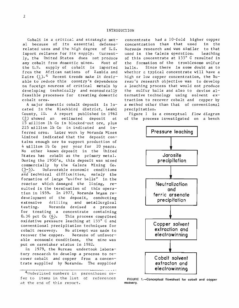
Figure 1 is a conceptual flow diagramof the process investigated on a bench
Pressure leaching
I
Jarositeprecipitation
•Neutralization
andferric arsenate
precipitation
,
Copper solventextraction andelectrowinning
,
Cobalt solventextracton andelectrowinning
FIGURE 1.-Conceptual f10wsheet for cobalt and copperrecovery.
the copperby solventacid and
scale. The process comprises (1) oxidative pressure leaching of the flotationconcentrate in an oxygen atmosphere at195 0 C, (2) precipitation of the majorportion of the iron and arsenic as sodiumjarosite, (3) neutralization of the filtrate from jarosite precipitation to remove the last traces of iron and arsenicas ferric-arsenate precipitate, (4) recovery of copper from the iron- andarsenic-free filtrate by solvent extraction with LIX 622 and electrowinning, and
(5) recovery of cobalt fromsolvent extraction raffinateextraction with a phosphinicelectrowinning.
Metal analyses in aqueous solutionswere deter-mined by atomic adsorptionspectrophotometry. Organic solutionswere digested in nitric acid-perchloricacid to destroy the organics; the metalsalts were dissolved in acid and analyzedby atomic adsorption.
DESCRIPTION OF FEED MATERIAL
The flotation concentrate used in thisinv~stigation was provided by Noranda.Table 1 shows the chemical analysis ofthe concentrate. For comparison, a concentrate analysis from a report of theNoranda Research Center is also includedin the table. The two concentrates wel:equite similar except for the higher levelof chalcopyrite in the concentrate
supplied to this laboratory; the difference resulted in a 10-~01d higher copperconcentration. The major mineral components present in both concentrates werepyrite, cobaltite, arsenopyrite, quartz,and silicate gangue minerals, with traceamounts of marcasite, magnetite, nativebismuth, pyrrhotite, sphalerite, and native copper.
OXIDATIVE PRESSURE LEACHING
Metal values were effectively dissolvedby leaching the concentrate with water atelevated temperatures under an oxygen atmosphere. Sulfuric acid, formed in situby contacting cobaltite flotation concentrate with water at elevated temperature and pressure in an oxidizing atmosphere, effectively dissolved metalvalues. Table 2 shows the effect ofleaching temperature on metal extraction in a 1-L Ti metal pressure reactor.Other test conditions were initial pulp
density of 10 pct solids, 50-psi oxygenoverpressure (oxygen pressure in excessof the saturated steam pressure at theoperating temperature), and 5-h leachingtime. A problem encountered at both 135 0
and 155 0 C was the formation of sulfurballs. In earlier industrial practiceat the Calera mill, these sulfur ballsoften grew to large dimensions and causedsevere mechanical difficulties. Typically, the balls contained, in weight percent, 0.36 As, 0.14 Co, 6.9 Cu, 35 Fe,
TABLE 1. - Analysis of Blackbird cobalt concentrate samples
Element Concentrate analysis, wt pct Element Concentrate analysis, wt pctThis .investigation Noranda This investigation Noranda
Ag•••••••• ' 0.18 '0.15 Mg•••••••• 0.142 0.058AI •••••.•• .60 .25 Moo ••••••• .04 .031As •••••••• 8 9.94 Ni .•••.••• .19 .13P....u •••••.•• 1.07 1.10 s......... 36.8 36.6Bi•.....•. .04 .41 Sh•••••••• .04 .02Ca•••••••• .06 .043 Se •••••.•• .02 .016Cd•••• g ••• <.01 .0005 Si02······ 7.4 6.8Co•••••••• 5.3 5.77 Te •••••••• ND .014Cu•••••••• 3.6 .36 Zn•••....• .03 .0061Fe•••••••• 35 3L6
ND Not determined. lTroy ounces per ton.

4
TABLE 2. - Effect of leaching temperature onmetal extraction
Leach Metal extracted, pct H2 SO4 intemperature, As Co Cu Fe Ni leach liquor,
°c giL135••••••••• 52.5 98.6 38.7 35.9 90.9 20.2155 ••••••••• 11.7 98.6 70.9 32.8 91.5 34175••••••••• 16.5 99.2 96.1 56.6 99.7 41195••••••••• 8.1 98.7 97 18.8 99.6 53
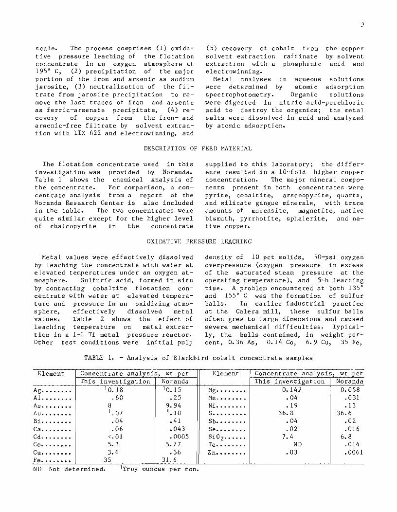
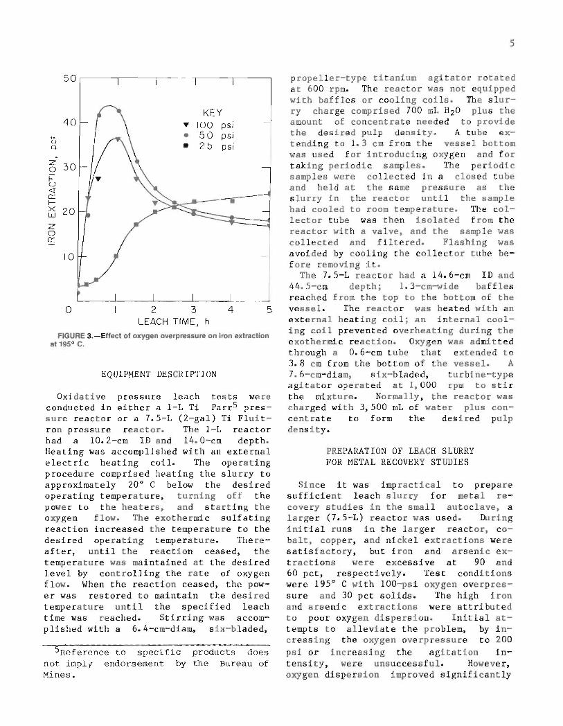
Figures 2 and 3 show the effect of oxygen overpressure on the rates of cobaltand iron extractions at 95 0 C and 10 pct
•+- 80ua.
2 345LEACH TIME, h
FIGURE 2.-Effect of oxygen overpressure on cobaltextraction at 1950 C.
ft
Z0f- 60u«0:::f- KEYx
'" 100 psiw 40~ • 50 psi« • 25 psim0 •u
20
solids. A 100-psi oxygen overpressureproduced the best combination of highcobalt extraction rates and minimal ironextraction. Maximum cobalt extractionwas achieved in approximately 2 h; however, iron extraction continued to decrease slightly at leaching times up to 5h. As a consequence, subsequent testwork was conducted using a 5-h retentiontime.
Initial pulp densities, ranging from 10to 30 pct solids, did not affect cobaltextraction; iron extraction increasedonly slightly at the higher densities.Subsequent test work was performed at thehigher pulp density because more concentrated leach solutions are produced andless autoclave capacity is required.
(2)
(1)
(3)
0.056 Ni, and 55.2 S. The higher proportion of copper and sulfur and the lowerproportion of arsenic, cobalt, and nickelrelative to the unleached concentrate indicates that these sulfur balls are derived primarily from chalcopyrite. Whenthe leaching temperature was raised tonear 195 0 C, an insoluble basic ferricsulfate, Fe203'2S03, formed; this reaction decreased both the sulfur ball formation and the iron extraction. Therefore, a 195 0 C leaching temperature wasadopted for subsequent test work on thehigh chalcopyrite concentrate. Lowerleaching temperature may be preferable for concentrates containing lesschalcopyri teo
The following equations represent themajor chemical reactions taking placeduring the oxidation pressure leach:
= 4 CUS04 + 4 Fe(OH)3 + 8 S.
Chalcopyrite:4 CuFeS2 + 4 H2S04 + 5 O2 + 2 H20
Pyrite:4 FeS2 + 15 02 + 2 H20
Cobaltite:4 CoAsS + 13 02 + 6 H20
Arsenopyrite:FeS2·FeAs2 + 7 02 + 2 H20
5
EQUIPMENT DESCRIPTION
FIGURE 3.-Effect of oxygen overpressure on iron extractionat 195 0 c.
5Reference to specific products doesnot imply endorsement by the Bureau ofMines.
PREPARATION OF LEACH SLURRYFOR METAL RECOVERY STUDIES
propeller-type titanium agitator rotatedat 600 rpm. The reactor was not equippedwith baffles or cooling coils. The slurry charge comprised 700 mL H20 plus theamount of concentrate needed to providethe desired pulp density. A tube extending to 1.3 cm from the vessel bottomwas used for introducing oxygen and fortaking periodic samples. The periodicsamples were collected in a closed tubeand held at the same pressure as theslurry in the reactor until the samplehad cooled to room temperature. The collector tube was then isolated from thereactor with a valve, and the sample wascollected and filtered. Flashing wasavoided by cooling the collector tube before removing it.
The 7.5-L reactor had a 14.6-cm ID and44.5-cm depth; 1.3-cm-wide bafflesreached from the top to the bottom of thevessel. The reactor was heated with anexternal heating coil; an internal cooling coil prevented overheating during theexothermic reaction. Oxygen was admittedthrough a 0.6-cm tube that extended to3.8 em from the bottom of the vessel. A7.6-cm-diam, six-bladed, turbine-typeagitator operated at 1,000 rpm to stirthe mixture. Normally, the reactor wascharged with 3,500 mL of water plus concentrate to form the desired pulpdensity.
Since it was impractical to preparesufficient leach slurry for metal recovery studies in the small autoclave, alarger (7.5-L) reactor was used. Duringinitial runs in the larger reactor, cobalt, copper, and nickel extractions weresatisfactory, but iron and arsenic extractions were excessive at 90 and60 pet, respectively. Test conditionswere 195 0 C with 100-psi oxygen overpressure and 30 pet solids. The high ironand arsenic extractions were attributedto poor oxygen dispersion. Initial attempts to alleviate the problem, by increasing the oxygen overpressure to 200psi or increasing the agitation intensity, were unsuccessful. However,oxygen dispersion improved significantly
542 3LEACH TIME, h
o
50
KEY40 'Y 100 psi- • 50 psi
u • 25 psia.~
Z 300~u<rn::~x 20wz0n::
10
Oxidative pressure leach tests wereconducted in either a 1-L Ti Parr5 pressure reactor or a 7.5-L (2-gal) Ti Fluitron pressure reactor. The 1-L reactorhad a 10.2-cm ID and 14.0-cm depth.Heating was accomplished with an externalelectric heating coil. The operatingprocedure comprised heating the slurry toapproximately 20° C below the desiredoperating temperature, turning off thepower to the heaters, and starting theoxygen flow. The exothermic sulfatingreaction increased the temperature to thedesired operating temperature. Thereafter, until the reaction ceased, thetemperature was maintained at the desiredlevel by controlling the rate of oxygenflow. When the reaction ceased, the power was restored to maintain the desiredtemperature until the specified leachtime was reached. Stirring was accomplished with a 6.4-cm-diam, six-bladed,

6
TABLE 3. - Results of large-scale leach tests
ND Not determlned.
Element or Ext ,(act ion, Leach liquor' Element or Extraction, Leach liquorcompound pct composition, lS/L compound pet composition giL
As •••••••• 26.4 8.6 H2S04' •••• ND 123Co•••••••• 99u3 17 Ni ..•..... 99.7 .77Cu••..•••• 99.5 13.8 Se •....... ND • allFe ••••••.. 41. 9 62 Z n••••.••• ND .096
,.
after the baffles were removed; thisallowed a vortex to form. These difficulties indicate that pilot-scale, continuous-leaching studies would be neededto optimize the reactor design.
After optimizing the 7.5-L reactor operation, several runs were conducted toprepare sufficient leach slurry for further studies. Table 3 shO'lo.lS the average
results from several tests at 195° C,laO-psi oxygen overpressure, and 30 petsolids in the initial slurry. The finalleach slurry contained 17.7 pet solids.Iron and arsenic extractions remainedhigher than expected from the small-scaletest results; however, these results maybe comparable to those of a large-scaleoperation.
LEACH LIQUOR PURIFICATION AND METAL RECOVERY
To prevent product contamination, ironand arsenic must be removed from theleach liquor prior to valuable metalrecovery. Preliminary testing showedthat iron could be removed by solventextraction with alkylphosphoric acids.This approach proved impractical fot' thefollowing reasons: (1) the high ironextraction, (2) the formation of a ferric-arsenate precipitate at the pHbest suited for iron extraction, and(3) stripping difficulties. As an alternative, jarosite precipitation was investigated to remove the iron together withthe arsenic.
JAROSITE PRECIPITATION
The formula for jarosite isMFe3(S04)2(OH)6, where M is an alkaliion. Jarosites can be formed at low temperatures; however, the formation rate isincreased significantly at temperaturesnear boiling. Sodium jarosite was formedin this investigation by adding Na2S04 tothe leach slurry at 95° C, adjusting thepH with milk of lime, and maintaining thepulp temperature at 95° C for the lengthof time shown in each test description.Forming the jarosite directly in theleach slurry, rather than in the filtrateafter removal of the leach solids, wasmore effective and reduced the number offiltration steps required. Attempts to
form the jarosite directly in the autoclave by adding Na2S04 and lime (CaO)near the end of the leach removed ironand arsenic, but reduced the cobalt extraction to 92 pet and formed a slo~
filtering slurry.
Sodium Sulfate Requirements
Sodium sulfate requirements for maximumiron and arsenic removal from the leachslurry were investigated in tests using(1) the stoichiometric amount needed toreact with all of the soluble iron and(2) a 40-pct excess. In both tes ts, theslurry was adjusted to pH 1.5 and heated4 h at 95° C. Iron precipitation increased from 94.4 to 99.1 pet and arsenicprecipitation increased from 96.6 to99.1 pct with the excess Na2S04' In subsequent tests, 40 pct excess Na2S04 wasused.
Effect of pH
Table 4 shows test results using various amounts of CaO to produce pH valuesranging from 1.27 to 2.07. Other testconditions were 40 pet excess Na2S04 and4 h heating at 95° C. Results show thatprecipitation at approximately pH 1.5produced maximum iron and arsenic removal without an excess loss of valuablemetals.
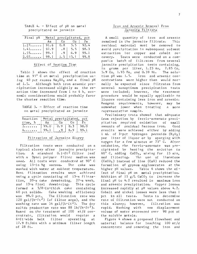
TABLE 4. - Effect of pH on metalprecipitated as jarosite
Final pH Metal precipitated, petAs Co Cu Fe
1. 27 •••.•• 91. 6 0.8 5. 5 92.41. 41 •••••• 97.9 .8 5. 5 98.31. 55...... 99.1 • 9 6.9 99.12. 07 •••••• 99.1 1.5 13. 1 99.8
Effect of Reation Time
Table 5 shows the effect of reactiontime at 95° C on met~l precipitation using 40 pet excess Na2S04 and a final pHof 1.5. Although both iron arsenic precipitation increased slightly as the reaction time increased from 1 to 4 h, economic considerations would probably favorthe shorter reaction time.
TABLE 5. - Effect of reaction timeon metal precipitated as jarosite
Reaction Metal preci itated, pettime, h As Co Cu Fe1••••••• 99.0 O. 9 8.3 98.04••••••• 99.1 • 9 6.9 99.1
Filtration of Jarosite Slurry
Filtration tests were conducted on atypical slurry after jarosite precipitation. A standard O. I-ft 2 filter leafwith a Dynel polymer filter medium wasused. All tests were conducted at 90° Cusing 15-in Hg vacuum. The cake waswashed with water at ambient temperature.Best filtration results were achievedusing a cycle consisting of 15-s filtration, 20-s cake dewatering, 27-s wash,and 13-s final dewatering. This cycleformed a 5/8-in-thick cake containing60 pet solids. Cake washing efficiencywas 99.0 pet. The filtration rate was120 gal/(h'ft 2 ) (of filter area), and thewashing rate was 54 gal/(h·ft 2 ). The drysolids production rate was 88 lb/(h·ft 2 ).Based on the treatment of 100 st/d concentrate, filtration would require a6-ft-wide belt filter operating at17.9 ft/min with a minimum filter lengthof 28 ft.
7
Iron and Arsenic Removal FromJarosite Filtrate
A small quantity of iron and arsenicremained in the jarosite filtrate. Thisresidual material must be removed toavoid precipitation in subsequent solventextraction for copper and cobalt recovery. Tests were conducted on a composiLe batch of filtLates from severaljarosite precipitation tests containing,i n g rams per 1it e r , 1. 2 5 As, 7• 8 5 Co,5.9 Cu, 1.95 Fe, and 0.39 Ni. The solution pH was 1.5. Iron and arsenic concentrations were higher than would normally be expected since filtrates fromseveral nonoptimum precipitation testswere included; however, the treatmentprocedure would be equally applicable toliquors containing less iron and arsenic.Reagent requirements, however, may besomewhat lower when treating a morerepresentative sample.
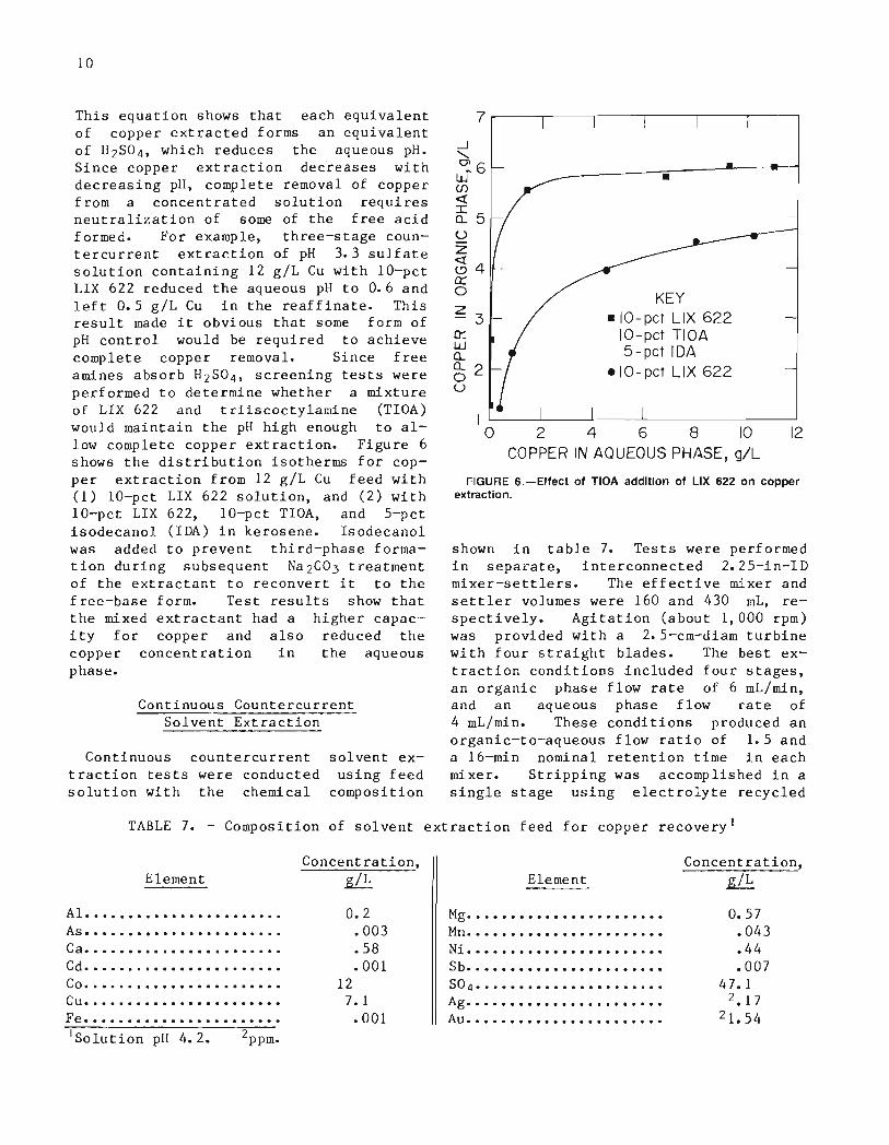
Preliminary tests showed that adequateiron rejection by ferric-arsenate precipitation required oxidation of smallamounts of residual ferrous iron. Goodresults were achieved either by adding1 mL of 3-pct hydrogen peroxide (H 20 2 )per liter of liquor or by sparging withoxygen for a few minutes at 75° C. Afteroxidation, the ferric-arsenate was precipitated by heating the solution to60° C, adding CaC0 3 , mixing for 15 min,and filtering. The use of limestone(CaC0 3 ) instead of lime (CaO) reduced theformation of gypsum agglomerates at thehigher pH values. Table 6 shows the ef'~
feet of final pH on metal precipitation.Addition of 15 g/L CaC0 3 to increase thefinal pH to 4.2 resulted in maximum ironand arsenic precipitation. Copper lossesincreased rapidly at pH values above 4.2.Cobalt and nickel losses were less than 1pet in all tests. Tests to determinerate of filtration were not conducted onthis slurry; however, filtration wasrapid. Washing with one displacementvolume of water recovered over 98 pct ofthe soluble metals.
Figure 4 shows a proposed flowsheet andmaterial balance for leaching 100 st/dconcentrate and ~emoving the iron and
8
Concentrate: 100 st IdIb
As .•... 16,000Co ..... 10,600Cu ...•.. 7,200Fe ..... 70,000N i ..... 380
Water: 466,832 Ib •Pt'· : Oxygen: 135,867 Ib I55,975 gal • ressure reoc Jon I
Milk of lime
Na2S04: I Jarosite Ib gal18,187 Ib I precipitation CoO .. 92,387 NApH20 .. 378,086 45,334
Wash water: 3 I 7 ,579 Ib38,079 gal J Filtration :
~•Filtrate: 9 I 3 , 8 I 5 Ib Filter coke: 669,83 I Ib101 ,002 gal Dry solids..... 349,688 IbIb giL H20(hydration).. 52, 162 Ib
As .. 38 0.045 H20(entralned).. 267 I 98 I IbCo .. /O,330 12.3Cu •. 6,403 7.6 IbFe •• 256 .30 As •........ 15,962N I •• 376 .45 Co •.......• 270
Cu ......... 797
3-pet-H20 2 solution: 8541bFe ......... 69,744N I •.......• 4
102 gal
I Neutralization and- ferric arsenate :CoC03: I I ,952 Iblprecipitation
IWash water: 37,672 Ib : CO2: 5,259 Ibl4,517 gal
I': Filtration :
lFiltrate: 930, 566 Ib Filter coke: 53.760 Ib
102,392 gal Dry solids..... 26 1826 IbIb giL H20(hydration) .. 5 ,430 Ib
As .. 1.75 0.002 H20(entroined).. 2 I ,504 IbCo .. 10,245.0 12.0Cu •. 6,061.0 7. I IbFe •. 0.85 .001 As ......... 36.3N i .. 373.0 .44 Co ...•..... 85.0
Cu •........ 342.0Fe .•....... 255.2N i ......... 3.0
Filtrate tocopper recovery
FIGURE 4.-Proposed flowsheet and material balance for leaching 100 stfd concentrate and removingthe Iron and arsenic.
9
TABLE 6. - Effect of pH on metal pre~ipitated
as ferric arsenate
Filtrate, CaC0 3 Metal precipitated, Filtrate composition,pH added, pct mg/L
giL As Cu Fe As Cu Fe1. 8 ...... 2 31. 5 0.01 9.0 480 5,200 1,900I. 9•....• 4 66 .03 20 220 5,200 1, 7002. o...... 6 73.3 .06 28 200 5,200 1,5002. 4...... 8 80 .07 38. 7 140 5,200 1,1502. 5..••.• 10 96.3 .16 87.1 20 5,200 2503. 6...... 12 98.9 ,,88 99.4 5 5,200 124. 2•••••• 1L, 99.5 309 99.9 3 5,000 14. 8•••••• 16 99.5 14.5 99.9 3 4,450 1
arsenic. The material balance is basedon the best laboratory test results foreach step of the process"
COPPER RECOVERY
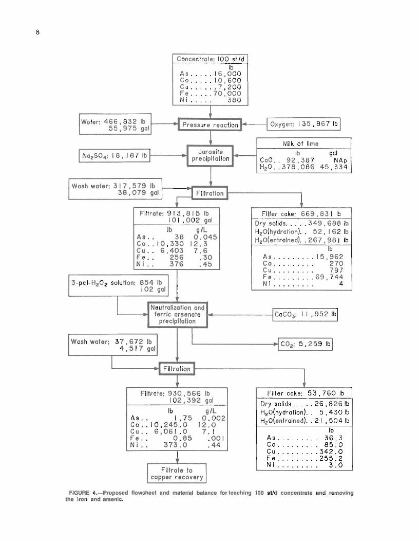
consequently, it was selected for furtherstudies.
pH Control
4
.,.
KEY• L1X 622• L1X 64.,. L1X 63
2 3EQUILIBRIUM pH
10-2 '-- --'-- -'- ----l... _
o
The following equation describes theextraction of copper by hydroxyoximes:
(2 R-H)org + (Cu 2+ + S04=)aq
(R2Cu)org + (2H+ + S04=)aq. (5)
.--..0«W
'f:' 103
ZW
U
~ 10 2
Wouz010 1
I-U<l:n:::~ 100wn:::w0..~ 10-1
U
FIGURE 5.-Effect of pH on copper extraction coefficient forvarious extractants.
Copper in the i~on" and arsenic-freefiltrate was recovered by a combinationsolvent extraction-electrowinning procedure. A hydroxyoxime-type extractant wasused to recover the copper, and thestripping cell was operated in a closedcircuit with the electrolytic cell. Theloaded strip liquor was fed directly tothe copper electrowinning cell, and thepartially depleted effluent electrolytewas recycled to the stripping operation.
Solvent Selection
Three of the more common chelating-typecopper extractants available, LIX 63,LIX 64, and LIX 622, were tested foreffectiveness in continuous countercurrent testingo The most effective,LIX 622, had the highest extraction coefficient at the lower pH values. Copperext~action coefficients were obtained byequilibrating equal volumes of 70-vol-pctextractant dissolved in kerosene withcopper-sulfate solution containing 6 giLCu at various pH values. The pH wasadjusted by adding concentrated H2S04or NH 40H as required. At pH 3, theloading for LIX 622, LIX 63, and LIX 64were 13.4, 15.0, and 7.3 giL Cu, respectively. Test results, shown in figure 5,indicate that LIX 622 is the most effective extractant at the lower pH values;
10
Continuous CountercurrentSolvent Extraction
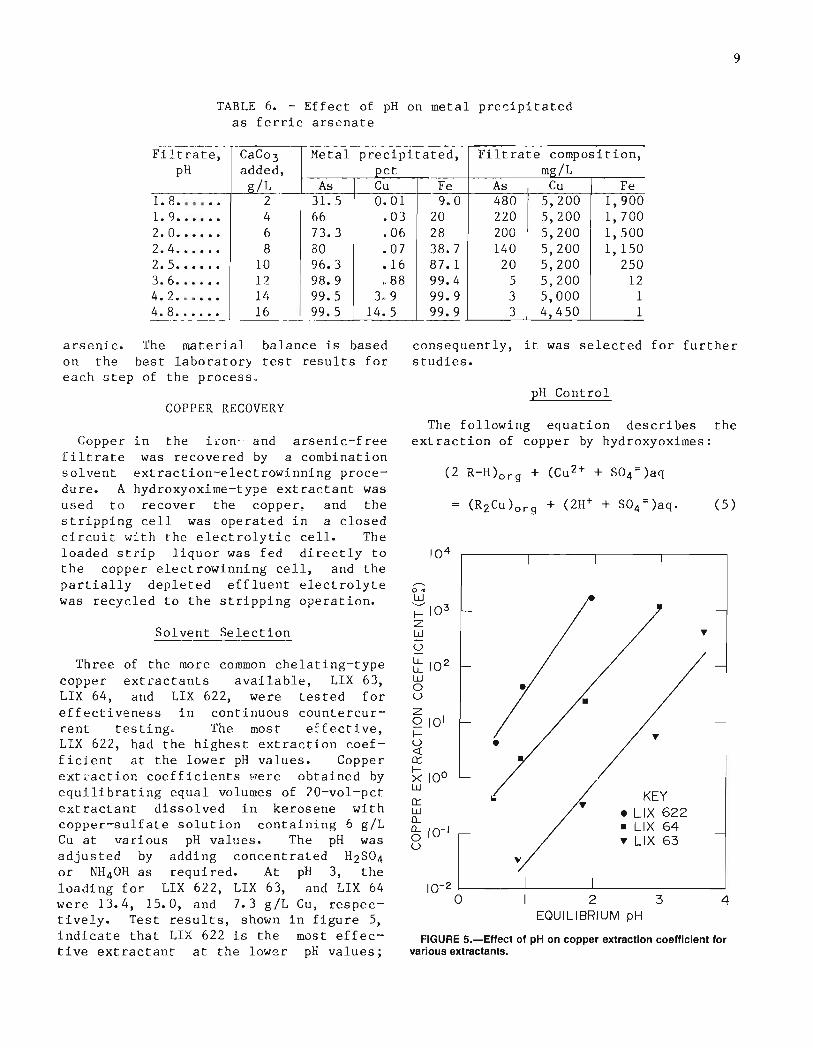
This equation shows that each equivalentof copper extracted forms an equivalentof H2S04, which reduces the aqueous pH.Since copper extraction decreases withdecreasing pH, complete removal of copperfrom a concentrated solution requiresneutralization of some of the free acidformed. For example, three-stage countercurrent extraction of pH 3.3 sulfatesolution containing 12 giL Cu with 10-pctLIX 622 reduced the aqueous pH to 0.6 andleft 0.5 giL Cu in the reaffinate. Thisresult made it obvious that some form ofpH control would be required to achievecomplete copper removal. Since freeamines absorb H2S0 4, screening tests wereperformed to determine whether a mixtureof LIX 622 and triiscoctylamine (TIOA)would maintain the pH high enough to allow complete copper extraction. Figure 6shows the distribution isotherms for copper extraction from 12 giL Cu feed with(1) 10-pct LIX 622 solution, and (2) with10-pct LIX 622, 10-pct TIOA, and 5-pctisodecanol (IDA) in kerosene. Isodecanolwas added to prevent third-phase formation during subsequent Na2C03 treatmentof the extractant to reconvert it to thefree-base form. Test results show thatthe mixed extractant had a higher capac'·'ity for copper and also reduced thecopper concentration in the aqueousphase.
7~----r---,----.--------'-----'----'
•
KEY• 10-pet L.IX 622
10-pet TIOA5-pet IDA
elO-pet L1X 622
-1"'-~6w
(f)
<t
~5uZ<34a:::o2
30:w0..0..2ou
rlGURE 5.-Effect of T10A addition of L1X 522 on copperextraction.
I o 2 4 6 8 10 12
COPPER IN AQUEOUS PHASE, giL
shown in table 7. Tests were performedin separate, interconnected 2. 25-in-IDmixer-settlers. The effective mixer andsettler volumes were 160 and 430 mL, respectively. Agitation (about 1,000 rpm)was provided with a 2.5-cm-diam turbinewith four straight blades. The best extraction conditions included four stages,an organic phase flow rate of 6 mL/min,and an aqueous phase flow rate of4 mL/min. These conditions produced anorganic-to-aqueous flow ratio of 1.5 anda 16-min nominal retention time in eachmixer. Stripping was accomplished in asingle stage using electrolyte recycled
solvent exusing feed
composition
Continuous countercurrenttraction tests were conductedsolution with the chemical
TABLE 7. - Composition of solvent extraction feed for copper recovery I
Concentration.Element ~ Element
Concentration.
~
AI. . . • . • • . • • • • • • . • . • • • . . • O. 2As. . . . . . . . . . . . . . . . . . . • . • • . 003Ca. . . . . . . . . . . . • . • . . . . . . . . . 58Cd....................... .001Co. • • . . • . . . . • • . • • • . • • • • . • 12cu....................... 7.1Fe....................... .001lSolution pH 4.2.
Mg•••••••••••••••••••••••Mn•••••••••••••••••••••••Ni •••.....••••.•••.•••.•.Sb•••••••••••••••••••••••SO 4 ••••••••••••••••••••••
Ag•••••••••••••••••••••••Au •••••••••••••••••••••••
0.57.043.44.007
47.12.17
21.54
11
Copper Electrowinning
Copper was electrowon from the loadedstrip liquor in a plastic cell 12.7 cmlong by 8.9 cm wide by 14.0 cm deep. Thecell contained three lead anodes, each7.6 em wide by 0.16 em (1/16 in) thick,and two copper starting sheets, each7.6 cm wide by 0.08 em (1/32 in) thick,that were immersed to a depth of 7.6 cmin the electrolyte. The spacing betweenthe anodes and cathodes was 1.3 em. Theelectrolyte contained a free sulfuricacid concentration of 150 giL. The cellwas operated at room temperature with acurrent density of 7.3 A/ft 2 of cathodearea. Most tests were run for 7 h ateach specified set of conditions. Copper
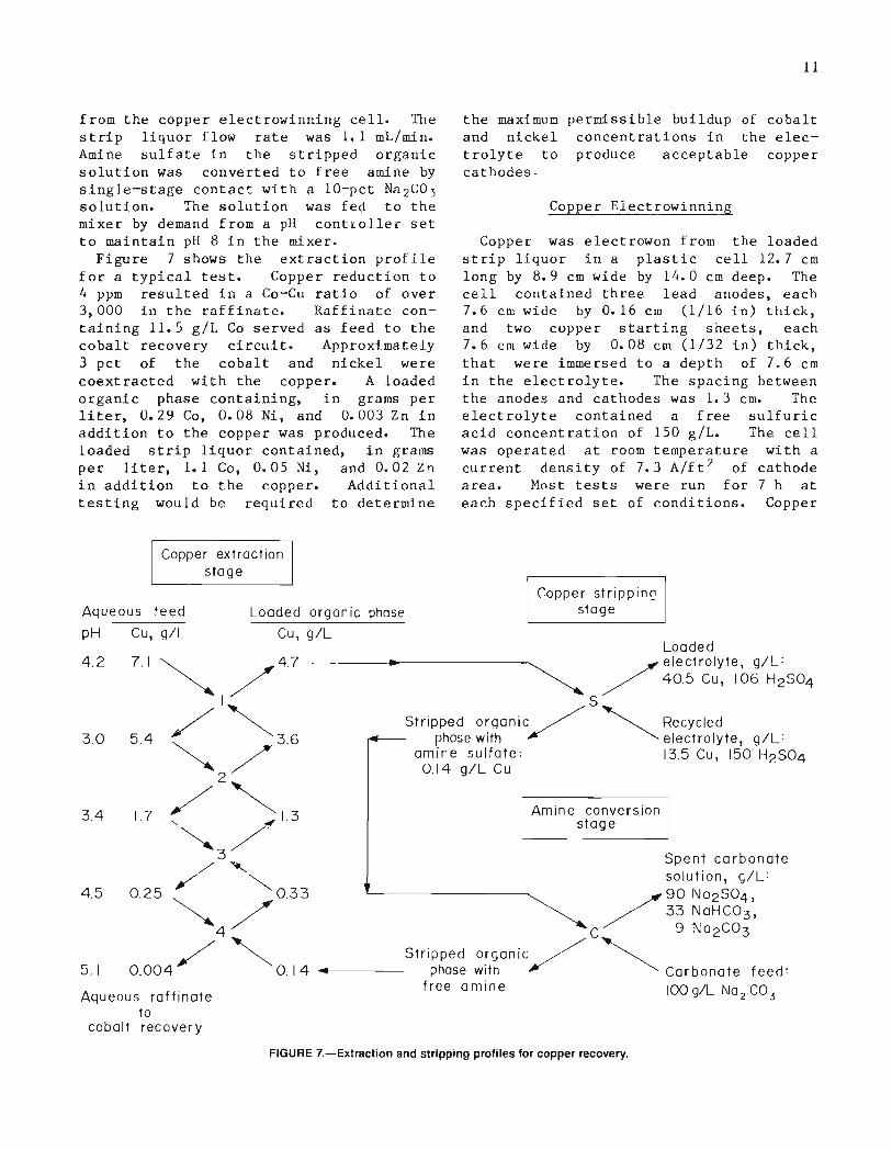
from the copper electrowinning cell. Thestrip liquor flow rate was 1.1 mL/min.Amine sulfate in the stripped organicsolution was converted to free amine bysingle-stage contact with a 10-pct Na2CO,solution. The solution was fed to themixer by demand from a pH controller setto maintain pH 8 in the mixer.
Figure 7 shows the extraction profilefor a typical test. Copper reduction to4 ppm resulted in a Co-Cu ratio of over3,000 in the raffinate. Raffinate containing 11.5 giL Co served as feed to thecobalt recovery circuit. Approximately3 pct of the cobalt and nickel werecoextracted with the copper. A loadedorganic phase containing, in grams perliter, 0.29 Co, 0.08 Ni, and 0.003 Zn inaddition to the copper was produced. Theloaded strip liquor contained, in gramsper liter, 1.1 Co, 0.05 Ni, and 0.02 Z!1in addition to the copper. Additionaltesting would be required to determine
the maximumand nickeltrolyte tocathodes.
permissible buildup of cobaltconcentrations in the elecproduce acceptable copper
Copper extractionstage
Aqueous feed
pH Cu, giL
Aqueous raffinateto
cobalt recovery
Copper strippin<]stage
Amine conversionstage
Loaded~ / electrolyte, giL:
/ 40.5 Cu, 106 H2S04
S
Stripped organic / '" Recycledphase with '/ ~ electrolyte, giL:
amine sulfate: 13.5 Cu, 150 H2S040.14 giL Cu
Loaded organic phase
Cu, giL
7.1~ /4.7
I
5.4 <"'36
2//'"1.7" /1.3~/.
/3'-. Spent ca rbonate/ ~ solution, giL:
0.25 '" 0.33 /90 Na2S04,""" / / 33 NaHC03,
4 C 9 Na2C03
/ ~ Stripped organic / '"0.004 0.14 ......1------- phase with / ~ Carbonate feed:
free amine 100 giL Na CO2 3
3.0
4.2
4.5
3.4
5.1
FIGURE 7.-Exlraction and stripping profiles for copper recovery.
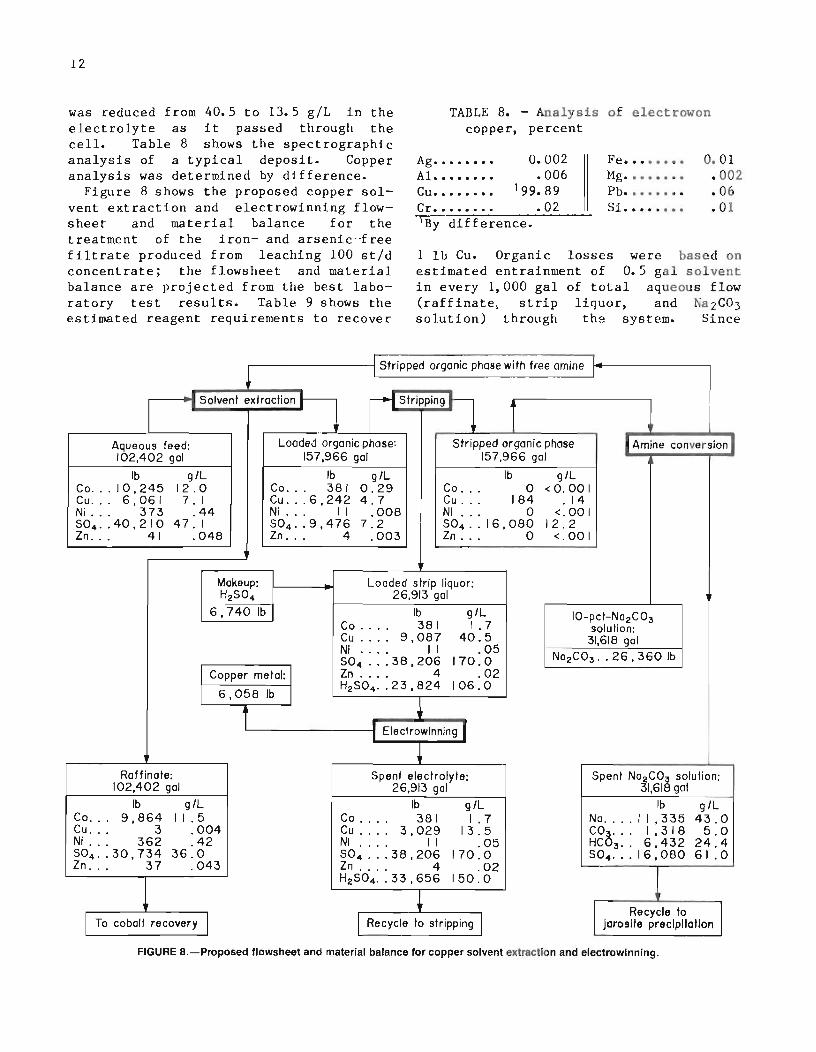
TABLE 8. - Analysis of electrowoncopper, percent
1 lb Cu. Organic losses were based onestimated entrainment of 0.5 gal solventin every 1,000 gal of total aqueous flow(raffinate, strip liquor, and Na2C03solution) through the system. Since
12
was reduced from 40.5 to 13.5 giL in theelectrolyte as it passed through thecell. Table 8 shows the spectrographicanalysis of a typical deposit. Copperanalysis was determined by difference.
Figure 8 shows the proposed copper solvent extraction and electrowinning flowsheet and material balance for thetreatment of the iron- and arsenic··freefiltrate produced from leaching 100 st/dconcentrate; the flowsheet and materialbalance are projected from the best laboratory test results. Table 9 shows theestimated reagent requirements to recover
Ag........ 0.002AI. • • • • • • • • 006Cu........ 199.89Cr. • • . • • . • .021By difference.
Fe........ 0.01Mg........ .002Ph. • . . . . • . .06Si. • • • • • • • .01
: Stripped organic phase with free amine :
i-: Solvent extraction r 5triPPing~ 1--
Aqueous feed: Loaded organic phose: Stripped organic phose IAmine conversion102,402 gal 157,966 gal 157,966 gal
Ib giL Ib giL Ib giLCo... IO,245 12.0 Co... 381 0.29 Co ... 0 <0.00 ICu... 6,061 7. I Cu ... 6,242 4.7 Cu ... 184 .14Ni ... 373 .44 NI ... I I .008 NI ... 0 <.001504, .40,210 47. I 504, .9,476 7.2 504 .. 16,080 12.2In ... 41 .048 In ... 4 .003 In ... 0 <.00 I
Makeup: Loaded strip liquor:H2 SO4 26,913 gal
6,740lb Ib giL 10-pcl-N02 C03Co .... 381 1.7 solution:Cu .... 9,087 40.5 31,618 galNI . . ~ . II .05 N0 2 C03 .. 26.360 IbS04 ... 38.206 170.0
Copper metal: In .... 4 .02
6,0581bH2 S04, .23.824 106.0
+: Electrowlnnlng I
Roffinote: Spent electrolyte: Spent N02 C03 solution:102,402 gal 26,913 gal 31,618 gal
Ib giL Ib giL Ib giLCo... 9,864 1 I .5 Co .... 381 1.7 No.... II ,335 43.0Cu ... 3 .004 Cu .... 3,029 13.5 CO&... 1,318 5.0NI ... 362 .42 NI I I 0·- HC 3 •• 6,432 24.4. 0S04 .. 30,734 36.0 S04 ... 38,206 170.0 504 ..• 16,080 61.0In . .. 37 .043 In .... 4 .02
1H2 S04.. 33,656 150.0
Recycle to II To cobalt recovery I I Recycle to stripping I Jarosite precipitation
FIGURE a.-proposed flowsheet and material balance for copper solvent extraction and electrowlnnlng.
13
TABLE 9. - Estimated reagentrequirements for copperrecovery
conversion of the amine sulfate to freeamine with Na2C03 forms a Na2S04 solutionthat probably could be recycled to thejarosite precipitation step, a creditcould be ~llowed for this Na2S04.
PhosphinicPhosphonic
RO~ ,-/0p/
R~ ~OH
Phosphoric
Work reported by Preston (~) indicatedthat the cobalt-nickel separation undercomparable conditions increases in the
Continuous CountercurrentSolvent Extraction
order phosphoric < phosphonic < phosphinic acid. This order of selectivity wasconfirmed in tests using sulfate solutions. Consequently, a phosphinic acidtype extractant, Cyanex 272, was selectedfor continuous countercurrent tests torecover cobalt.
1. 14.4.011.011.0055
'.063
Requirements,lb/lb Curecovei-ed
Reagent
IDA••••••••••••••••••••••••Kerosene•••••••••••••••••••'0.01 gal.
H2S0 4••••••••••••.••••••...Na 2C03- ••••••••••••••••••••LIX 622••.•••••••••••••••••TlOA•••••••••••••••••••••••
COBALT RECOVERY
Cobalt in the copper solvent extraction raffinate was recovered by (1) solvent extraction with Cyanex 272 (analkyl phosphinic acid-type extractant),(2) stripping the loaded extract withelectrolyte recycled from the cobaltelectrowinning cell, and (3) returningthe loaded strip liquor to the electro··winning cell for cobalt recovery. No attempt was made to recover the low concentration of nickel in the copper solventextraction raffinate. Since the onlycontaminant added to the aqueous solutionwas sodium, the levels of other contaminants were low, and the pH was near 7,the cobalt solvent extraction raffinate could be disposed of in an existingnatural stream.
Solvent Selection
Organophosphorus acids were consideredto be the most promising family ofreagents for cobalt recovery from thecopper extraction raffinate. Commercially available organophosphorus acids include phosphoric, phosphonic, and phosphinic acids. The following diagramsshow the structure of the three types.
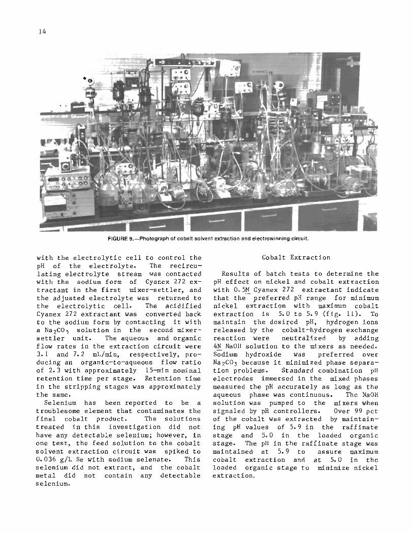
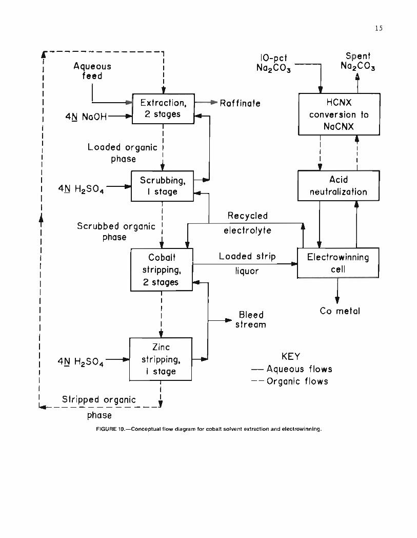
Continuous countercurrent solvent extraction tests were conducted using copper solvent extraction raffinate with thechemical composition shown in table 10.The organic extractant was unmodified0.5M Cyanex 272 extractant dissolved inkerosene. Tests were performed in separate, interconnected mixer-settlers withthe same dimensions as those used forcopper solvent extraction. Figure 9 is aphotograph of the cobalt solvent extraction and electrowinning circuit. Agitation (about 1,000 rpm) was provided withflat, 2.5-cm-diam, four-bladed paddles.The extraction circuit, shown in simplified form in figure 10, comprised twoextraction stages, one scrubbing stage,two low-acid cobalt stripping stages, andone high-acid zinc stripping stage. Additionally, a two-unit mixer-settlersystem was operated in closed circuit
TABLE 10. - Composition of feed solution l
for cobalt recovery, grams per liter
As ••••••••• 0.001 Fe ••••••••• 0.002Ca ••••••••• .60 Ni ••.•••••• .42Co••••••••• 11.5 SO 4 •••••••• 37Cu••••••••• .004 Zn.•.•••••• .043ISolution pH 7.
14
FIGURE 9.-Photograph of cobalt solvent extraction and electrowinning circuit.
with the electrolytic cell to control thepH of the electrolyte. The recirculating electrolyte stream was contactedwith the sodium form of Cyanex 272 extractant in the first mixer-settler, andthe adjusted electrolyte was returned tothe electrolytic cell. The acidifiedCyanex 272 extractant was converted backto the sodium form by contacting it witha Na2C03 solution in the second mixersettler unit. The aqueous and organicflow rates in the extraction circuit were3.1 and 7.2 mLlmin, respectively, producing an organic-to-aqueous flow ratioof 2.3 with approximately 15-min nominalretention time per stage. Retention timein the stripping stages was approximatelythe same.
Selenium has been reported to be atroublesome element that contaminates thefinal cobalt product. The solutionstreated in this investigation did nothave any detectable selenium; however, inone test, the feed solution to the cobaltsolvent extraction circuit was spiked to0.036 giL Se with sodium selenate. Thisselenium did not extract, and the cobaltmetal did not contain any detectableselenium.
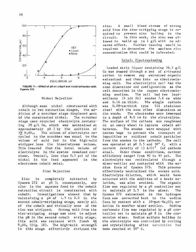
Cobalt Extraction
Results of batch tests to determine thepH effect on nickel and cobalt extractionwith Oo5M Cyanex 272 extractant indicatethat the preferred pH range for minimumnickel extraction with maximum cobaltextraction is 5.0 to 5.9 (fig. 11). Tomaintain the desired pH, hydrogen ionsreleased by the cobalt-hydrogen exchangereaction were neutralized by adding4N NaOH solution to the mixers as needed.Sodium hydroxide was preferred overNa2C03 because it minimized phase separation problems. Standard combination pHelectrodes immersed in the mixed phasesmeasured the pH accurately as long as theaqueous phase was continuous. The NaOHsolution was pumped to the mixers whensignaled by pH controllers. Over 99 pctof the cobalt was extracted by maintaining pH values of 5.9 in the raffinatestage and 500 in the loaded organicstage. The pH in the raffinate stage wasmaintained at 5.9 to assure maximumcobalt extraction and at 5.0 in theloaded organic stage to minimize nickelextraction,
15
4IIII
HCNX
IIII,
conversion toNaCNX
~..... Raffinate•.-
I
II
Loaded organic I
phase +
Extraction,4N NaOH-...... 2 stages f+---
"'----~---
~--------------1I I
Aqueous I
feed :
I
,
_ Scrubbing,-~
- I stageIII
Scrubbed organic :phase •
Acidneutralization
Cobaltstripping,2 stages
IIIII•
II _ Stripped organic ,I~------------
phase
-Zinc
stripping,I stage
I
KEY- Aqueous flows-- Organic flows
FIGURE 10.-Conceptual flow diagram for cobalt solvent extraction and electrowinning.
16
Cobalt Electrowinning
zinc. A small bleed stream of strongacid from the zinc·~tripping stage is required to prevent zinc buildup in thecircuit. In this work, th~ zinc was allowed to build up to 1 giL with no adverse effect. Further testing would berequired to determine the maximum zincconcentration that could be tolerated.
KEYg Cobolt• Nickel
80
uc.260of=u~ 40t-Xw
I00 ,-----,------,--,-----,------,---=:lII===,--~
Zinc Rejection
Nickel Rejection
Loaded strip liquor containing 36.5 giLCo was pumped through a bed of a~tivated
carbon to remove any entrained organicextractant and then into an electrowinning cell. The electrolytic cell had thesame dimensions and configuration as thecell described in the copper electrowinning section. The cell had two leadantimony (4 pct Sb) anodes 7.6 cm wideand 0.16 cm thick. The single cathodewas 0.08-cm-thick type 316 stainlesssteel with the same other dimensions asthe anode. The electrodes were immersedto a depth of 9.0 em in the electrolyte.The surface of the cathode was roughenedon an eme~y wheel to improve cobalt adherence. The anodes were wrapped withcanvas bags to prevent the transport ofimpurities or oxidized cobalt particlesfrom the anodes to the cathode. The cellwas operated at pH 2.5 and 50 0 C, with acurrent density of 15 A/ft 2 (of cathodearea). Under these conditions, currentefficiency ranged from 92 to 95 pct. Theelectrolyte was recirculated th~ough amixer--settler and contacted with the sodium form of Cyanex 272. This processeffectively neutralized the excess acid.Electrolyte dilution, whi~h would haveoccurred with the addition of a b~sic solution, was also avoided. The organicflow was regulated by a pH controller setto maintain pH 2.5 in the mixer. TheCyanex 272 extractant in the hydrogenform was converted back to the sodiumform by contact with a 10-pct-Na2C03 solution in another mixer settler. Sodiumcarbonate flow was regulated by a pH controller set to maintain pH 8 in the conversion mixer. Sodium sulfate buildup inthe electrolyte was controlled by coolingand crystallizing after saturation hadbeen reached at 50 0 C.
764 5EQUILIBRIUM pH
FIGURE H.-Effect of pH on cobalt and nickel extraction withCyanex 272.
20
Although some nickel coextracted withcobalt in two extraction stages, the addition of a scrubber stage displaced mostof the coextracted nickel. The scrubberstage used recycled electrolyte contain-"ing 28 giL Co, which was maintained atapproximately pH 3 by the addition of4N H2S0 4 , The volume of electrolyte recycled to the scrubber was equal to thevolume of acid fed to the high-acidstripper less the bleed-stream volume.This insured that the total volume ofelectrolyte in the system remained constant. Overall, less than 0.5 pct of thenickel in the feed appeared in theelectrowon cobalt metal.
Zinc is completely extracted byCyanex 272 at pH 3; consequently, anyzinc in the aqueous feed to the cobaltextraction circuit is coextracted withcobalt. Investigations showed that bymaintaining a pH of 1.5 to 2.0 in thesecond cobalt-stripping stage, neat"ly allof the cobalt and virtually none of thezinc was stripped. Strong acid from thezinc-~tripping stage was used to adjustthe pH in the second cobalt strip stage;this acid was replaced with fresh 4NH2S0 4 (fig. 10). The high-acid strengthin this stage effectivAly stripped the
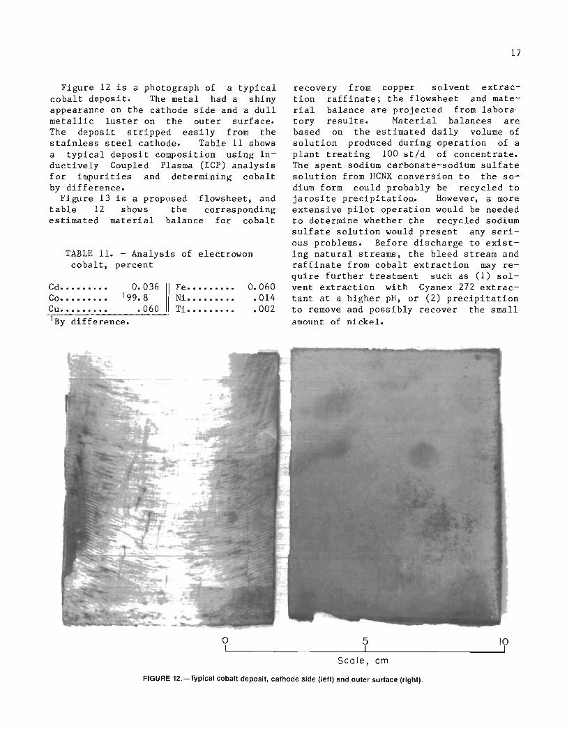
TABLE 11. - Analysis of electrowoncobalt, percent
Figure 12 is a photograph of a typicalcobalt deposit. The metal had a shinyappearance on the cathode side and a dullmetallic luster on the outer surface.The deposit stripped easily from thestainless steel cathode. Table 11 showsa typical deposit composition using Inductively Coupled Plasma (ICP) analysisfor impurities and determining cobaltby difference.
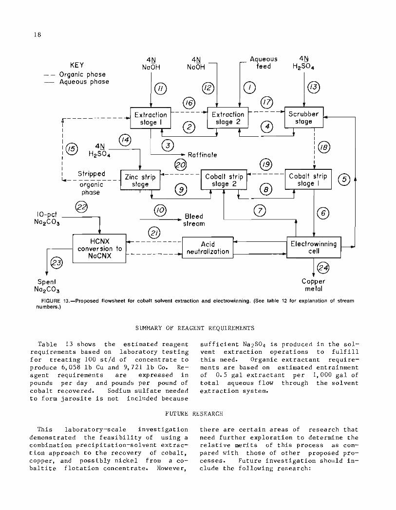
Figure 13 is a proposed flowsheet, andtable 12 shows the correspondingestimated material balance for cobalt
lBy difference.
Cd•••••••••Co•••••••••Cu ••••••.••
0.036'99.8
.060
Fe. • ••••••• 0.060Ni. . . • • . . . • . 014Ti......... .002
17
recovery from copper solvent extraction raffinate; the flowsheet and material balance are projected from labora'tory results. Material balances arebased on the estimated daily volume ofsolution produced during operation of aplant treating 100 st/d of concentrate.The spent sodium carbonate-sodium sulfatesolution from HCNX conversion to the sodium form could probably be recycled tojarosite precipitation. However, a moreextensive pilot operation would be neededto determine whether the recycled sodiumsulfate solution would present any serious problems. Before discharge to existing natural streams, the bleed stream andraffinate from cobalt extraction may require further treatment such as (1) solvent extraction with Cyanex 272 extractant at a higher pH, or (2) precipitationto remove and possibly recover the smallamount of nickel.
oI
5I
Scale, em
10I
FIGURE 12.-Typical cobalt deposit, cathode side (left) and outer surface (right).
18
KEYOrganic phaseAqueous phose
4NNoOH
®
4NNoOH -
@
Aqueousr- feed
(}) @
rElectrowinning r---
cell
@ ®t' ~------+ E t t' 1------. S bb
r-----------+ Extrac Ion x rac Ion cru eri stage I 0 stage 2 f4\ stage
"t. , \J • :® '-- ----1 L-- ----I I:0 4N 0 i@
I v..:::.J H2 SO.. Raffinate I
: @ @ ~~__ ~!~~~~ __ Zinc strip foI------·- Cobalt strip 4------ Cobalt strip '5'
organic stage '9' stage 2 '8' stage I \.:::.Jphase .t--__\:!.)__-Jf .1....-_"V__-.Jf
@ fiO\ '7'~ Bleed \!..)
stream
@HCNX f4---------- Acid
conversion toNaCNX 1----------+ neutralization
Coppermetal
FIGURE 13.-Proposed flowsheet for cobalt solvent extraction and electrowinning. (See table 12 for explanation of streamnumbers.)
SUMMARY OF REAGENT REQUIREMENTS
Table 13 shows the estimated reagentrequirements based on laboratory testingfor treating 100 stld of concentrate toproduce 6,058 lb Cu and 9,721 lb Co. Reagent requirements are expressed inpounds per day and pounds per pound ofcobalt recovered. Sodium sulfate neededto form jarosite is not included because
sufficient Na2S04 is produced in the solvent extraction operations to fulfillthis need. Organic extractant requirements are based on estimated entrainmentof 0.5 gal extractant per 1,000 gal oftotal aqueous flow through the solventextraction system.
FUTURE RESEARCH
This laboratory-scale investigationdemonstrated the feasibility of using acombination precipitation-solvent extraction approach to the recovery of cobalt,copper, and possibly nickel from a cobaltite flotation concentrate. However,
there are certain areas of research thatneed further exploration to determine therelative merits of this process as compared with those of other proposed processes. Future investigation should include the following research:

19
TABLE 12. - Estimated material balance for cobaltsolvent extraction and electrowinning
agentumptionbid-O~·_·_--
ooooooooo9 NaOH1 NAOH2 H2S043 H2S0 4ooooooo4 Na2C03o
_.-Flow Metal concentration, Metal flow rat_e, Ib/d Solu- Re
Stream' rate, giL Co Ni Zn tion consgal/day Co Ni Zn pH 1102,402
--I ..... 11.5 0.42 0.043 9,864.0 362.0 36. 7 7.02••••• 146,879 1.4 .465 .002 1, 723 574 2.4 5. 93••••• 152,328 .061 .28 .0004 81. 4 358.4 • 5 54••••• 26,634 19 1.8 .002 4,247 403.4 .4 2. 95..... 18,108 28 • 12 .001 4,247 20. 7 .2 1.96••••• 136,419 36.5 .13 .001 41,716 145.5 1. 2 4.27••••• 118,311 28 • 12 .001 27,748 123.4 1 1.98••••• 136,419 33.2 • 11 • 5 37,895 126. 1 568.4 1.69••••• 18,108 1.7 .063 1 256. 7 9.6 150.9 <0
10••••• 4,341 1. 7 .063 1 61. 8 2. 19 36.2 <011 .•••• 5,449 NAp NAp NAp NAp NAp NAp NAp 7,2612•.••• 17,843 NAp NAp NAp NAp NAp NAp NAp 23,8013.•••• 8,526 NAp NAp NAp NAp NAp NAp NAp 13,9314••••• 22,449 NAp NAp NAp NAp NAp NAp NAp 36,681S••••• 236,096 .008 .006 .015 15. 7 11. 8 29.5 NAp16.•••• 236,096 .84 .115 .016 1,657.5 227.8 31. 4 NAp17••••• 236,096 7. 1 • 21 .034 14,045.5 418.3 66. 1 NAp18••..• 236,096 7. 1 .018 .034 14,045.5 36. 1 65.9 NAp19••.•• 236,096 5. 17 .068 .32 10,224.5 16. 7 633. 1 NAp2O••••• 236,096 • 17 .012 • 11 334.2 23.6 216.6 NAp21 ••.•• 6,592 NAp NAp NAp NAp NAp NAp NAp22•.... 5,186 NAp NAp NAp NAp NAp NAp NAp 4,3223..... NAp NAp NAp NAp 9,721 1.5 0 NApNAp Not applicable.lCorresponds to stream numbers shown on figure 13.
TABLE 13. - Estimated reagent requirements for treating 100 st/d concentrate
Operation ReagentReagent
Ib/drequirements
Ib/lb Corecove red14.09.51.21.01
• 72. 7
.007
.007
.0034'.0063.25. 2.44.019
1.013
IDA•.•.•..••...•......•
Na2C03·················LIX 622 .
Kerosene•.•...•.•....•.
TlOA•••••••.•.••.••..•.
H2 SO 4••••••••••••••••••
Na2C03·················
Leaching. .. . . . . . . . . . . . . . . .. .. . . . . . . . . . Oxygen .Jarosite precipitation••••••••••.••••• Lime•••••••••••••••••••Ferric-arsenate precipitation••••••••• Limestone•••••••••••••.
3 pet H2 0 2 •••••••••••••
Copper solvent extraction............. H2S04 ••••••.••••••.•.•.
Cobalt solvent extraction•.••.•••••••• NaOH•••..•••.••••••••••
135,86792,38711,952
1102.46,740
26,360676733.5
155.931,07050,6154,324
Cyanex 272............. 180Kerosene............... 1125-,--- --L..__::....=....:=..:c:..::. -1---------'.-------
1Gallons.
20
Pilot-scale investigations should beconducted using a continuous feed reactorbecause it was difficu to cate results when seal up from a l-L to a7.5-L batch reactor.
The cobalt solvent extraction withits many recirculating streams should berun longer at s tate conditions todetermine whether any buildup of impurities in these streams would cause seriousproblems.
More work is needed to determinewhat treatment, if any, is needed to prepare the various effluent streams fordischarge to existing natural streams.
The disposition of the gold and silver should be determined and proceduresdeve to recover these precious metals. Based on an estimated recovery, annual gold and silver productionwould be 2,500 and 5,800 tr oz per year,
i vely.A comparison of economic evaluations
for both the precipitation-solvent extraction process described in this reportand the process described Harris,Monette, and St (~), should be madeto determine the most economical.
CONCLUS IONS
The ective of devising an alternative process for recovering cobalt andcopper from sulfate by liquidextraction rather than tation wasachieved. Over 91 pct the cobalt and84 pet of the copper were recovered fromcobaltite concentrate by a process thatinvolved (1) oxidative pressure leaching,(2) jarosite p tat ion, (3) ferric-arsenate p tation, (4) selectivesolvent extraction of copper witha mixed hydroxyomine-amine extractant,
(5) electrowinning of copper from recirculating acidic strip liquor, (6) selec"tive solvent extraction of cobalt fromcopper solvent extraction raffinate withan alkyl phosphinic acid extractant, and(7) electrowinning cobalt from recirculating weak acidic strip r. The electrowon copper was 99.89 pct pure, and theelectrowon cobalt was 99.8 pct pure. Aneconomic evaluation remains to bepe rf ormed.
REFERENCES
J. H., Jr. Cobalt, a MaBuMines Ie 8103, 1962,
Present, and Future. Pure and Appl.Chem., v. 1962, pp. 683-699.
6. Harris, G. B. , S. Monette, andR. W. St Hydrometallu cal Treatment of Blackbird Cobalt Concentrate.Paper rometallurgy: Research, ne-ve and Plant Practice. Metall.Soc. 1982, pp. 139-150.
7. Preston, J. S. Solventof Cobalt and Nickel byAcids. 1. Comparison of c,Phosphonic, and Phosphinic Acid terns.Hydrometall., v. 9, 1982, pp. 115-133.
PressureGarfield Refinery.
8, 19 pp. 1093-
1. Kirk, W. S. Cobalt. Sec. in BuMines Mineral Commodity Summaries 1985,pp. 36-37.
2. Biterials Survey.139 pp.
3. Mitchell, J. S.and Reduction at theMin. Eng. Y.), v.1095.
4. Cobalt Pressure Leachingand at Garfield. J. Met.,v. 9, No.3, 1957, pp. 343-345.
5. Fasse M. W., Jr. r Atmosric Extractive Metallurgy, Its Past,
u.s. GOVERNMENT PRINTING OFFICE: 1987 605·01 32 INT.-BU.OF MINES,PGH.,PA. 28592