redexim-blec box-graderuser manual and parts book redexim-blec box-grader 1800 / laser-grader 1800...
TRANSCRIPT

User Manual and Parts Book
REDEXIM-BLEC BOX-GRADER 1800 / LASER-GRADER 1800
Serial number:
Original manual
Kwekerijweg 8
3709JA Zeist
The Netherlands
Tel.: (31)30-6933227
Fax: (31)30-6933228
Email: [email protected]
www.redexim.com
ATTENTION:
IT IS OF THE UTMOST IMPORTANCE TO READ THIS USER MANUAL CAREFULLY PRIOR TO USING THE LASER-GRADER IN ORDER TO USE THE MACHINE SAFELY AND TO OBTAIN THE BEST RESULTS.
1724 English 952.120.008

2
FOREWORD
Congratulation on your Box-Grader purchase. For safe and long-lasting operation of this Box-Grader, it is necessary to read and to understand this user manual. It is impossible to work safely with this machine without complete knowledge of the content of the user manual.
The Box-Grader is not a machine that works independently. It is the user’s responsibility to use the correct shovel or other towing vehicle. The user must also check the towing vehicle/Box-Grader combination on safety aspects such as noise level, user instructions and risk analysis.
The following pages deal initially with the general safety instructions. Every user should know these safety instructions and apply them. At the end of this page, a registration card is inserted. This registration card should be returned to enable us to deal with potential future claims.
This user manual lists many instructions that are numbered in sequence. You should follow
this sequence. A is an indication of a safety instruction. A means a tip and/or note.
All information and technical specifications provided at the moment that this document is published are the most recent ones. Design specifications may be changed without prior notice.
WARRANTY CONDITIONS
WITH DELIVERY THIS BLEC-REDEXIM MACHINE IS GUARANTEED AGAINST MATERIAL DEFECTS.
THIS WARRANTY IS VALID FOR A PERIOD OF 12 MONTHS FROM THE PURCHASE DATE.
BLEC-REDEXIM WARRANTIES ARE SUBJECT TO THE ‘GENERAL CONDITIONS FOR SUPPLY OF PLANT AND MACHINERY FOR EXPORT, NUMBER 188’ THAT ARE PUBLISHED UNDER THE AUSPICES OF THE UNITED NATIONS ECONOMIC COMMISSION FOR EUROPE.
REGISTRATION CARD
For your own information, fill in the table below:
Serial number of the machine
Dealer name
Date of purchase
Remarks

3
!! SAFETY INSTRUCTIONS !!
Figure 1
The BLEC Box-Grader is designed for safe use. This can only be achieved if you completely follow the safety instructions described in this manual. Read and understand (Figure 1) the manual before you start using the BLEC-Redexim machine. If the machine is not used as described in this manual, this can result in injuries and/or damage to the machine.
INTENDED USE OF THE MACHINE AND OBLIGATIONS OF THE USER
Treating fields/lawns is the only purpose of the machine. Any other use is improper. The manufacturer will not accept any liability for damage resulting from improper use. All risks occurring with this are entirely at the expense of the user. All persons assigned to operate, maintain and repair the machine by the owner must completely read and understand the operation manual and in particular the chapter of Safety Instructions. The machine is manufactured according to the latest technical understanding and is safe to use. Modifications to the Box-Grader (including its operations) that have a negative impact on safety must be rectified immediately. The user is obliged to check the Box-Grader for visible damage and defects before using the Box-Grader. For safety reasons it is in principle not permitted to make changes or adjustments to the Box Grader (except those approved by the manufacturer). If modifications to the Box-Grader have been made, then the current CE marking is cancelled. The person that has made these modifications has to apply for a new CE marking himself. Following the use, maintenance and repair instructions prescribed by the manufacturer is also considered proper use of this machine.
The user is responsible for a safe combination of the Box-Grader and the towing vehicle. This entire combination must be tested for noise, safety, risk and user friendliness. User instructions should also be drafted. Dress appropriately during work activities to the Box-Grader. Wear sturdy shoes with steel toecaps, long trousers and tie up long hair. Do not wear loose clothing. The general applicable health & safety (Dutch: ARBO) regulations must also be followed in addition to the instructions in this user manual.
Relevant traffic regulations also apply in case of using public roads.

4
REQUIREMENTS FOR THE ENVIRONMENT AND TOWING VEHICLES
Inspect the area to be treated before using the Box-Grader. Remove loose obstacles and avoid irregularities.
As described in the Technical Data, always use the Box-Grader in combination with a towing vehicle that is suitable for this job.
Do not use the Box-Grader in the dark, in heavy rain/storm or on slopes with an angle larger than 20 degrees.
REQUIREMENTS DURING MAINTENANCE, REPAIR AND ADJUSTMENTS
Keep a record of the repair activities.
When unskilled people use, maintain or repair the machine, this could result in injuries to the user and to third parties. This must be avoided!
Use only original BLEC parts for maintenance or repairs because of the safety of the machine and of the user.
Only authorised technical personnel may carry out repairs to the Box-Grader.
In case of maintenance, adjusting and repairs, it is necessary to block the Box-Grader in order to prevent sinking away, driving off and/or sliding off.
If a hydraulic installation is present, you should always make it pressure-free before working on this installation.
Used oil/grease is harmful to the environment. Dispose of these substances according to the regulations that apply in your location.
REQUIREMENTS PRIOR TO AND DURING WORK ACTIVITIES TO THE MACHINE
Attach the Box-Grader to the towing vehicle according to the regulations. (Danger of injuries!)
NEVER use the Box-Grader in the absence of protective guards and safety stickers.
Check the Box-Grader for loose bolts, nuts and components before every operation.
Check whether you have a clear field of vision – both close by and far away – before you start moving.
All persons who are going to operate the Box-Grader must be familiar with all the functions and control elements of the Box-Grader before starting any work activities.
NEVER crawl under the Box-Grader. If necessary, tip over the Box-Grader to work at the bottom side.
If present, check the hydraulic hoses regularly and replace these when the hydraulic hoses are damaged or appear old. The hoses that are replaced should comply with the technical requirements of the manufacturer.

5
Location of the Safety Stickers
Figure 4
SAFETY STICKERS
Safety stickers are located on both sides of the Box-Grader (Figures 2 and 3). These safety stickers must always be clearly visible and legible and must be replaced if they have become damaged.
Figure 2
- In case of maintenance, adjustments and repair, always switch OFF the engine of the towing vehicle.
- Keep a distance of minimum 4 metres if the
machine is operating (except the operator).
Figure 3
- Prior to using the machine, the operators of the machine must read the user manual carefully.

6
EU DECLARATION We – Redexim BV, Utrechtseweg 127, 3702 AC Zeist, Holland – declare entirely under our own responsibility that the product: BOX-GRADER WITH A MACHINE NUMBER AS INDICATED ON THE MACHINE AND INDICATED IN THIS MANUAL to which this declaration refers, complies with the stipulation of the 2006/42/EC machine directive and with the NEN-EN-ISO 12100 : 2010 and NEN-EN-ISO 13857 : 2008 norms. Zeist, 26/09/2016
A.C. Bos Manager Operations & Logistics Redexim Holland
7
TABLE OF CONTENTS
WARRANTY CONDITIONS ...................................................................................................2
REGISTRATION CARD .........................................................................................................2
!! SAFETY INSTRUCTIONS !! .............................................................................................3
EU DECLARATION ...............................................................................................................6
1. TECHNICAL DATA OF THE BOX-GRADER .............................................................8
2. GENERAL DESCRIPTION .........................................................................................8
2.1 BOX SCRAPER KIT ...................................................................................................9
3. TECHNICAL DATA OF THE LASER-GRADER ....................................................... 10
3.1 LASER-GRADER KIT .............................................................................................. 10
4. FIRST INSTALLATION ............................................................................................ 11
5. ATTACHING AND DETACHING THE BOX-GRADER ............................................. 12
5.1 ATTACHING THE BOX-GRADER ........................................................................... 12
5.2 DETACHING THE BOX-GRADER ........................................................................... 13
6. ATTACHING AND DETACHING THE LASER-GRADER......................................... 13
6.1 ATTACHING THE LASER-GRADER ....................................................................... 13
6.2 DETACHING THE LASER-GRADER ....................................................................... 14
7. MACHINE SETTINGS .............................................................................................. 15
7.1 ADJUSTING THE RIPPING TINES .......................................................................... 15
7.2 ADJUSTING THE LIFT-HEIGHT OF THE LASER-GRADER’S WHEELS ............... 16
7.3 ADJUSTING THE HEIGHT OF THE TOW BAR ....................................................... 16
7.4 KNIFE OF THE BOX-GRADER ................................................................................ 17
8. TRANSPORTING THE MACHINE ............................................................................ 17
9. SAFETY WHEN USING THE MACHINE .................................................................. 18
9.1 THE WORKING SPEED ........................................................................................... 18
9.2 USING THE MACHINE ............................................................................................. 18
9.3 START/STOP PROCEDURE ................................................................................... 18
10. TROUBLE SHOOTING (PROBLEM ANALYSIS) ..................................................... 19
11. MAINTENANCE ....................................................................................................... 19
12. TECHNICAL INFORMATION: LUBRICATION POINTS BOX SCRAPER ................ 20
12.1 TECHNICAL INFORMATION: LUBRICATION POINTS LASER-GRADER ............. 20
8
1. TECHNICAL DATA OF THE BOX-GRADER
Type 1800
Recommended tractor Tractor with a 20-50 hp engine and minimum 480kg (1050 lbs) lifting capacity at 610mm behind the ball
Hydraulic connection of the tractor
One (1) single-acting valve or one (1) double-acting valve
Working width 1.8 m (70.8”)
Working speed Depending on the conditions and the required result
Three-point connection Cat. 1-2
Weight of the Box-Grader 325 kg (715 lbs)
Dimensions (L x W x H) 0.9x1.9x0.8 m (34.1”x73.6”x31.5”)
Number of ripping tines 8
Working depth of the ripping tines
25-75 mm (1”-2.9”)
Standard components Set of ripping tines
Optional Box Scraper kit
Box-Grader Swivel Bogy kit
Box-Grader Scraper kit Laser Pole kit
2. GENERAL DESCRIPTION
The Box-Grader 1800 can spread and level soil. By means of a Box Scraper kit or Wheel kit, these machines can be expanded to a grader/laser-grader that can level soil with great accuracy and control.
The height of the wheels can be adjusted independently per set of two. To move the two frames independently, it is necessary to remove the connecting pipe between the frames.
9
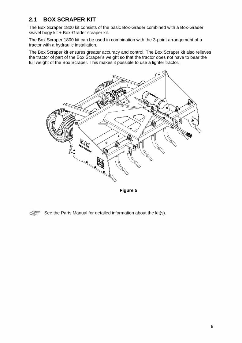
2.1 BOX SCRAPER KIT
The Box Scraper 1800 kit consists of the basic Box-Grader combined with a Box-Grader swivel bogy kit + Box-Grader scraper kit.
The Box Scraper 1800 kit can be used in combination with the 3-point arrangement of a tractor with a hydraulic installation.
The Box Scraper kit ensures greater accuracy and control. The Box Scraper kit also relieves the tractor of part of the Box Scraper’s weight so that the tractor does not have to bear the full weight of the Box Scraper. This makes it possible to use a lighter tractor.
Figure 5
See the Parts Manual for detailed information about the kit(s).

10
3. TECHNICAL DATA OF THE LASER-GRADER
Type 1800
Capacity of the towing vehicle 40 - 60 pk
Hydraulic connection of the tractor
One (1) single-acting valve or one (1) double-acting valve
Working width 1.8 m (70.8”)
Working speed Depending on the conditions and the required result
Weight of the Box-Grader 620 kg (1365 lbs)
Dimensions (L x W x H) 3.0x1.9x1.2 m (118”x75”x47.1”)
Number of ripping tines 8
Working depth of the ripping tines
25 - 75 mm (1”- 2.9”)
Wheel pressure 1.5 bar
Grease EP 2
Standard components Set of ripping tines
Optional Laser Pole kit
3.1 LASER-GRADER KIT
The Laser-Grader 1800 consists of the basic Box-Grader combined with a Laser-Grader 1800 wheel kit.
The Laser-Grader is suitable for use in combination with a single adjusting laser system or a double adjusting laser system. A different hydraulic valve and hoses are needed for a double adjusting laser system.
In a double adjusting laser system, the height of the wheels can be adjusted independently per set of two. For a correct functioning, there must be at least two lasers and a hydraulic valve to control the cylinders independently of each other.
The wheel can also be attached to each other for a single adjusting laser system.
Figure 6
See the Parts Manual for detailed information about the kit(s).

11
4. FIRST INSTALLATION
When using the Box-Grader for the first time, the machine has to be prepared as follows:
MAKE SURE THAT THE CABLE/CRANE/LIFT CAN HOIST MINIMUM TWICE THE WEIGHT OF THE MACHINE. (SEE CHAPTER 1.0 ‘TECHNICAL DATA’ FOR THE WEIGHT DETAILS.)
1. Attach cables to the hoisting points. 2. Using a crane, lift the machine approx. 100mm (4”) off the ground.
3. Pull the pallet from under the machine. Subsequently, carefully place the
machine on the ground.
!! NEVER CRAWL UNDER THE MACHINE !!
4. Mount any optional kits/parts.
See the Parts Manual for detailed information about mounting.
12
5. ATTACHING AND DETACHING THE BOX-GRADER
Attaching and detaching the Box-Grader has to be done carefully. Follow the instructions below:
5.1 ATTACHING THE BOX-GRADER
Prior to attaching the machine, check the following the points:
- Check whether the Box-Grader is undamaged and whether it is safe to attach and use the machine.
- Check whether the bolts and nuts are tightened with the correct torque. - Check whether all safety stickers are on the machine and whether these are
undamaged and easily readable. Never use the machine if it has damaged or unreadable stickers.
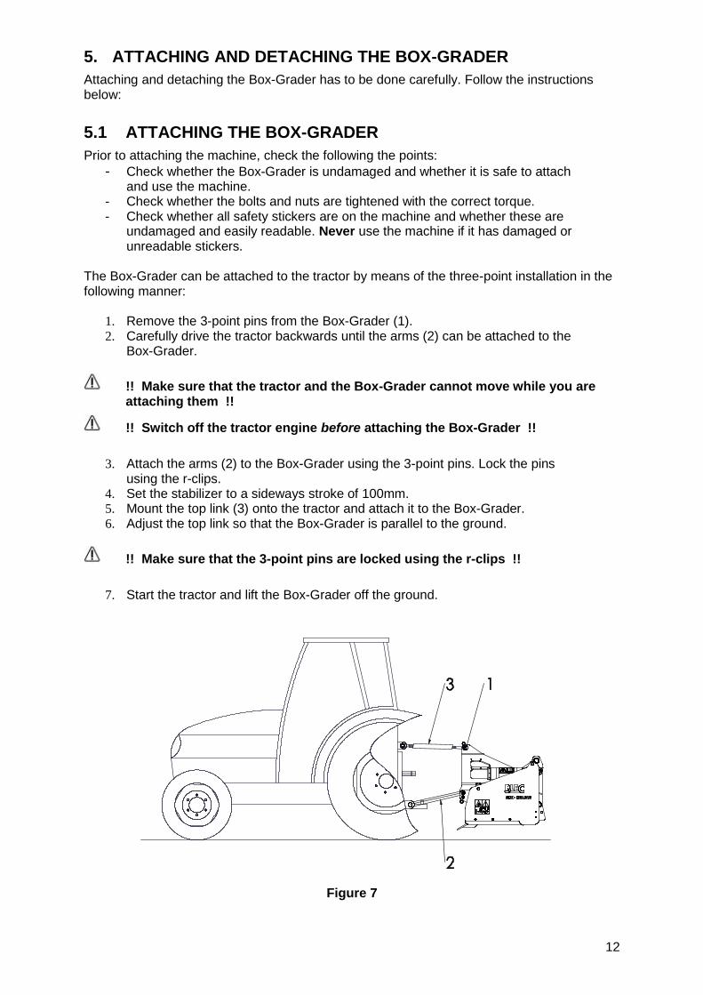
The Box-Grader can be attached to the tractor by means of the three-point installation in the following manner:
1. Remove the 3-point pins from the Box-Grader (1). 2. Carefully drive the tractor backwards until the arms (2) can be attached to the
Box-Grader.
!! Make sure that the tractor and the Box-Grader cannot move while you are attaching them !!
!! Switch off the tractor engine before attaching the Box-Grader !!
3. Attach the arms (2) to the Box-Grader using the 3-point pins. Lock the pins
using the r-clips. 4. Set the stabilizer to a sideways stroke of 100mm. 5. Mount the top link (3) onto the tractor and attach it to the Box-Grader. 6. Adjust the top link so that the Box-Grader is parallel to the ground.
!! Make sure that the 3-point pins are locked using the r-clips !!
7. Start the tractor and lift the Box-Grader off the ground.
Figure 7
13
5.2 DETACHING THE BOX-GRADER
The machine has to be detached in the following manner (see Figure 7):
1. Drive to a spot where the tractor and Box-Grader are in a horizontal position.
!! Make sure that the Box-Grader and the tractor cannot move while you are detaching them !!
!! Switch off the tractor engine before attaching the Box-Grader !!
2. Carefully place the Box-Grader on the ground. 3. Loosen the top link and remove it. 4. Loosen the lowest arms.
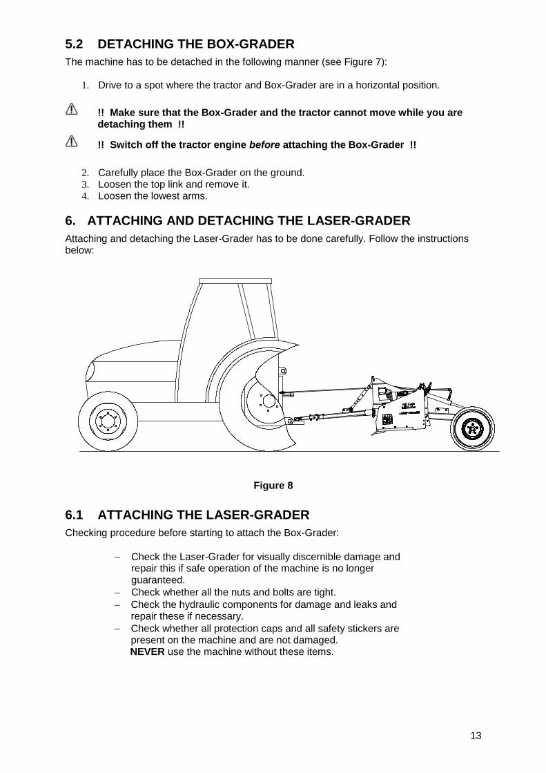
6. ATTACHING AND DETACHING THE LASER-GRADER
Attaching and detaching the Laser-Grader has to be done carefully. Follow the instructions below:
Figure 8
6.1 ATTACHING THE LASER-GRADER
Checking procedure before starting to attach the Box-Grader:
Check the Laser-Grader for visually discernible damage and repair this if safe operation of the machine is no longer guaranteed.
Check whether all the nuts and bolts are tight.
Check the hydraulic components for damage and leaks and repair these if necessary.
Check whether all protection caps and all safety stickers are present on the machine and are not damaged. NEVER use the machine without these items.

14
The attachment procedure is as follows (Figure 8):
1. Carefully drive the tractor backwards so that the towing hook can be attached to the tractor.
!! Make sure that the tractor is blocked well and cannot move on its own accord !!
!! Switch off the tractor before descending !!
2. Attach the Laser-Grader to the tractor by inserting the pin of the tractor’s hitch
point through the towing hook of the Laser-Grader and secure the pin. 3. Attach the hydraulic hoses to the tractor. 4. Start the tractor and activate the hydraulic port of the lifting mechanism. Lift
the machine.
6.2 DETACHING THE LASER-GRADER
The machine can be detached from the tractor in the following manner (See Figure 8):
1. Drive the Laser-Grader to a parking area with a firm / flat surface.
!! Make sure that the tractor is blocked well and cannot move on its own accord !!
2. Carefully lower the Laser-Grader onto the ground by activating the hydraulic
port for the set of wheels.
!! Make sure that the Laser-Grader stands stable on the ground before descending from the tractor !!
!! Switch off the tractor before descending !!
3. Detach the tow bar from the tractor.
4. Detach the hydraulic hoses.
!! Make sure that the Laser-Grader is stable !!
5. Start the tractor and drive off.
15
7. MACHINE SETTINGS
The Box-Grader and the Laser-Grader have various options for optimal settings.
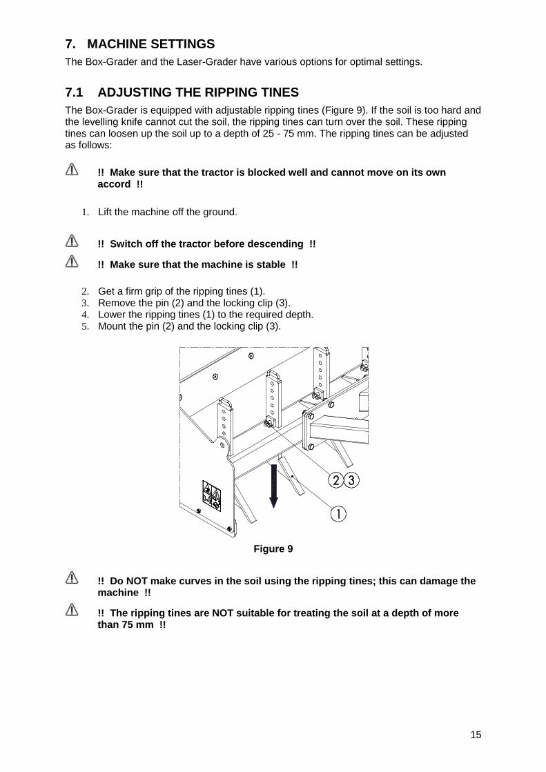
7.1 ADJUSTING THE RIPPING TINES
The Box-Grader is equipped with adjustable ripping tines (Figure 9). If the soil is too hard and the levelling knife cannot cut the soil, the ripping tines can turn over the soil. These ripping tines can loosen up the soil up to a depth of 25 - 75 mm. The ripping tines can be adjusted as follows:
!! Make sure that the tractor is blocked well and cannot move on its own accord !!
1. Lift the machine off the ground.
!! Switch off the tractor before descending !!
!! Make sure that the machine is stable !!
2. Get a firm grip of the ripping tines (1). 3. Remove the pin (2) and the locking clip (3). 4. Lower the ripping tines (1) to the required depth. 5. Mount the pin (2) and the locking clip (3).
Figure 9
!! Do NOT make curves in the soil using the ripping tines; this can damage the machine !!
!! The ripping tines are NOT suitable for treating the soil at a depth of more than 75 mm !!
16
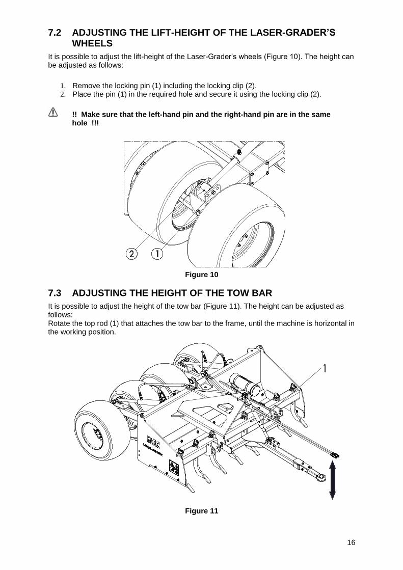
7.2 ADJUSTING THE LIFT-HEIGHT OF THE LASER-GRADER’S WHEELS
It is possible to adjust the lift-height of the Laser-Grader’s wheels (Figure 10). The height can be adjusted as follows:
1. Remove the locking pin (1) including the locking clip (2). 2. Place the pin (1) in the required hole and secure it using the locking clip (2).
!! Make sure that the left-hand pin and the right-hand pin are in the same hole !!!
Figure 10
7.3 ADJUSTING THE HEIGHT OF THE TOW BAR
It is possible to adjust the height of the tow bar (Figure 11). The height can be adjusted as follows: Rotate the top rod (1) that attaches the tow bar to the frame, until the machine is horizontal in the working position.
Figure 11
17
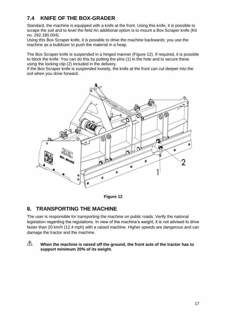
7.4 KNIFE OF THE BOX-GRADER
Standard, the machine is equipped with a knife at the front. Using this knife, it is possible to scrape the soil and to level the field An additional option is to mount a Box Scraper knife (Kit no. 292.180.004). Using this Box Scraper knife, it is possible to drive the machine backwards: you use the machine as a bulldozer to push the material in a heap. The Box Scraper knife is suspended in a hinged manner (Figure 12). If required, it is possible to block the knife. You can do this by putting the pins (1) in the hole and to secure these using the locking clip (2) included in the delivery. If the Box Scraper knife is suspended loosely, the knife at the front can cut deeper into the soil when you drive forward.
Figure 12
8. TRANSPORTING THE MACHINE
The user is responsible for transporting the machine on public roads. Verify the national
legislation regarding the regulations. In view of the machine’s weight, it is not advised to drive
faster than 20 km/h (12.4 mph) with a raised machine. Higher speeds are dangerous and can
damage the tractor and the machine.
When the machine is raised off the ground, the front axle of the tractor has to support minimum 20% of its weight.

18
9. SAFETY WHEN USING THE MACHINE
Before using the machine, you should check the following:
9.1 THE WORKING SPEED
The working speed is limited to 12 km/h (7.5mph). It is NOT recommended to drive faster because that will damage or cause excessive wear & tear to the machine and damage the subsoil.
9.2 USING THE MACHINE
Before using the machine in a location, you should check the following items:
1. Are there loose objects in the field? First remove these objects. 2. Are there slopes? The maximum slope is 20 degrees for this machine. 3. Are there cables/pipes buried in the ground? If so, determine their
depth and adjust the working depth of the machine to 60% of the depth of the cables/pipes.
4. Is there danger of flying objects (e.g., balls) that distract the attention of the driver? If so, the machine CANNOT be used.
5. Is there danger of sinking/sliding away? If so, postpone the processing until conditions improve.
6. If the soil is frozen or very wet, postpone the activities until conditions
improve.
7. Do not make sharp turns.
9.3 START/STOP PROCEDURE
The start procedure is VERY important. If this procedure is not executed as described below, it might result in serious damage to the machine. The start procedure is as follows:
1. Check the machine for loose components and look whether all components function properly.
!! If loose components are observed or components do not function properly, the problems must be solved before using the machine !!
2. Drive to the spot where the processing should take place. 3. Engage the tractor in the correct gear. 4. Slowly lower the machine until it reaches the required working depth. The
maximum depth that can be removed per round is 20 - 30 mm. 5. Make sure that the machine is horizontal in the working position. If not, adjust
the height of the tow bar / top rod (see Section 8.3). 6. If there is a rear-wheel, make sure that it always touches the ground;
otherwise, it is possible that the Box-Grader buries itself deeper into the ground and does not achieve a level condition of the surface that is treated.
Stopping occurs as follows:
1. Slowly lift the machine off the ground. 2. Go to the next location and start again as described above.

19
10. TROUBLE SHOOTING (PROBLEM ANALYSIS)
Problem Possible cause Solution
Treated surface is not level.
Wheel cylinders are not set to the same height.
Put the left-hand pin and the right-hand pin in the same hole.
Wheel pressure is not equal. Inflate the wheels up to the indicated wheel pressure.
Worn knife at the front Replace or repair the knife.
The tractor does not have sufficient traction.
Soil is too wet. Postpone treating the soil.
Machine is adjusted too deep.
Raise the machine so that the working depth becomes less deep.
Ripping tines too deep Raise the ripping tines (Section 7.1).
Machine does not reach its working depth.
Box Scraper knife is stuck, Remove the blocking pins from the Box Scraper knife (Section 7.4).
Machine is not level. Adjust the length of the tow bar / top rod (Section 7.3).
11. MAINTENANCE
Time schedule Check / Grease point Method
Before every use
Check for loose bolts / nuts.
Tighten loose bolts / nuts with the correct tightening moment.
Presence and readability of the safety stickers
Replace these if not present or damaged.
Check whether the ripping times are at the same height.
Put the ripping times at the same height.
Check the wheel pressure. Set the wheel pressure at 1.5 bar.
Check the hydraulic system. Replace or repair damaged components.
After every use
Clean the machine. Remove sand and dirt from the machine.
After the first 20 working hours
(new or repaired)
Check for loose bolts / nuts.
Tighten loose bolts / nuts with the correct tightening moment.
After every 50 hours Provide the lubrication points with grease.
Use EP2 grease 1 shot
Check the wheel pressure. Set the wheel pressure at 1.5 bar.
Check the wheel bolts. If necessary, tighten the wheel bolts.
20
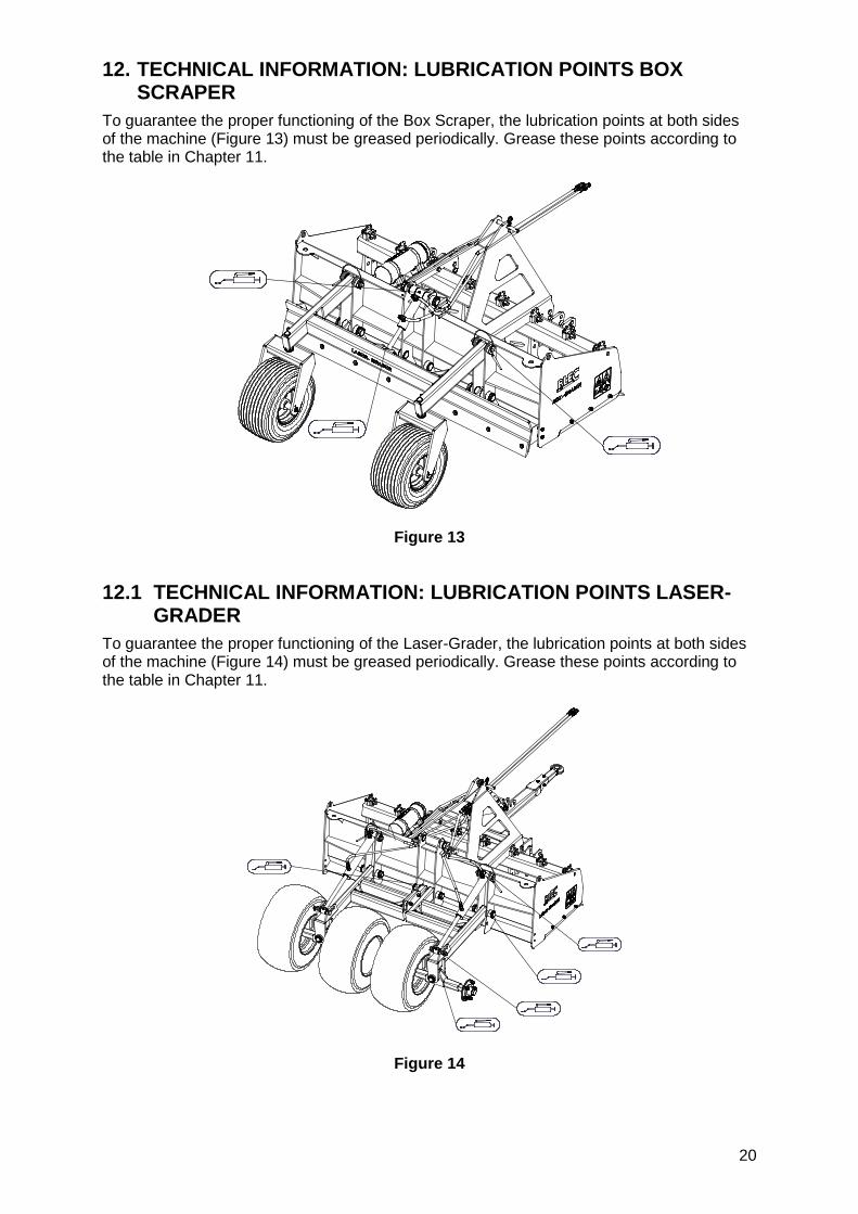
12. TECHNICAL INFORMATION: LUBRICATION POINTS BOX SCRAPER
To guarantee the proper functioning of the Box Scraper, the lubrication points at both sides of the machine (Figure 13) must be greased periodically. Grease these points according to the table in Chapter 11.
Figure 13
12.1 TECHNICAL INFORMATION: LUBRICATION POINTS LASER-GRADER
To guarantee the proper functioning of the Laser-Grader, the lubrication points at both sides of the machine (Figure 14) must be greased periodically. Grease these points according to the table in Chapter 11.
Figure 14