reduce metastability by using a user grey cell methodology
TRANSCRIPT

Blue Pearl Software, SJy Copyright 2014 1
Reduce Metastability by Using a User Grey Cell™ Methodology for IP and FPGA Clock Domain Crossing Analysis
2/19/2014
Shakeel Jeeawoody
Vice President, Marketing
This paper introduces a novel technique for Intellectual Property (IP) and FPGA clock domain crossing
(CDC) analysis using Blue Pearl’s User Grey Cell™ methodology rather than the traditional Black Box
methodology.
Growth of IP-based Design
As design complexity escalates, designers increasingly rely on commercial or existing IPs to meet project
deadlines rather than designing everything from scratch. According to Semico Research, over the next
couple of years, the number of IPs per design will increase from an average of 50 to a staggering 180.
The difficulty of IP integration and design verification will undoubtedly grow exponentially. Even today,
many design teams complain that it takes too long for integration and verification using existing
methodologies. Just imagine the resulting dreadful situations as the number of IP per design goes up. To
alleviate these types of issues, EDA vendors need to provide breakthrough methodologies. Previously,
Blue Pearl Software introduced the Grey Cell methodology, which was discussed at DAC 2012 and
elaborated on EETimes.
With the recently introduced User Grey Cell™ methodology, Blue Pearl enables IP providers and FPGA
designers to reduce the risk of missing CDC issues. In this paper, we illustrate how the recently
introduced patent-pending User Grey Cell™ methodology reduces metastability.
Leading cause of metastability
Designs today integrate components/IPs from many sources that operate with independent clocks with
different frequency and phase relationship. This is done to bring data into the design from different
sources or to change frequency in order to optimize power. The added complexity of disabling many
logic cones means verification engineers need to be more vigilant.

Blue Pearl Software, SJy Copyright 2014 2
Whenever there are setup or hold time violations in any flip-flop, it can enter a state where its output is
unpredictable. This state is known as metastable state. It could well be that the flip-flop will settle in a
known state. But due to dependencies on thermal and induced noise, one cannot be certain on the time
it takes to settle. The likelihood of a functional failure due to metastability increases with clock
frequency.
When components or IPs with different clock phase/frequency interface, the receiving logic flip-flop may
violate setup or hold time causing the output to not settle to a stable “1” or “0” state. This metastable
state can get propagated through the design as erroneous states causing functional failures. Hence it is
important for designers to find portions of their designs where CDC can occur. Designers then insert
logic to greatly reduce the likelihood of propagating erroneous data due to metastable signals.
Failure of the Black Box methodology
As discussed earlier, the required components/IPs come from varied sources. They could be acquired in
synthesizable RTL format, protected IP format, simulation models, or non-synthesizable formats. If the
IP is in the form of a synthesizable RTL, then it is relatively straightforward to do CDC analysis through it.
However, for the other formats, the IPs have traditionally been treated as black boxes i.e. the analysis
will not use any knowledge of the internals of the IP. In a black box methodology, the CDC analysis will
stop at each IP boundary and treat it as an end point with no relationship whatsoever with what’s inside
the IP.
As designers rely more and more on IPs, the number of black boxes included in the analysis is increasing.
Thus, the risk of missing critical CDC issues grows. Moreover, since the IPs are instantiated in
hierarchical designs, it quickly becomes impossible to manually trace and decide whether a particular
black box can cause a CDC issue.
Won’t IEEE P1735 solve the Black Box issue?
The IEEE project P1735 intends to describe IP encryption markup for design information formats, and
thus enable design flows that provide interoperability between IP sources, tools, integrators and users
of the IP. This is driven primarily by IP providers who want to protect their know-how and thus encrypt
their IP. P1735 provide guidelines for key management, together with encryption and decryption
algorithms. This enables inter-operable IP encryption and thus allows specific EDA tools to see the
“inside” of the IP.
Once P1735 is finalized, it will solve the CDC analysis for a synthesizable RTL IP assuming that once
decrypted, the tool has enough information to perform the analysis through the IP. However, this does
not completely address all the reasons why designers settle for a Black Box methodology. Designers still

Blue Pearl Software, SJy Copyright 2014 3
need to handle the non-synthesizable models, simulation models, behavioral models and/or still
incomplete models. For these components, encryption/decryption still does not help in enabling a
complete CDC analysis. Thus, P1735 still does not solve all the issues of using a Black Box methodology.
Even though the IPs can be encrypted and decrypted with proper key management, some IP developers
are still not convinced that the IP will not end up in the wrong hands. Consequently, Blue Pearl Software
developed the User Grey Cell methodology that works on all types of IP, without the need to ever ship
the proprietary information. In fact, designers can perform CDC analysis through the FPGA vendor
protected/generated IPs.
Basic CDC Analysis
Before we get into the details of User Grey Cell, let us do a quick refresher on basic CDC analysis.
A clock domain crossing occurs whenever data is transferred from a flip-flop driven by one clock to a
flip-flop driven by another clock. Traditional simulation and/or static timing analysis methods are not
sufficient to verify that the data is transferred consistently and dependably across clock domains. Thus,
CDC analysis tools emerged to assist designers in checking for these potential issues. Let’s point out that
some FPGA designers tend to wait to debug in the lab. However, it is better to use a verification tools on
the RTL rather than waiting for the lab.
A basic CDC analysis tool should check and report on some simple issues, e.g. existence of
unsynchronized and synchronized schemes, report even if one bit of a bus can cause CDC, check if data
is being clocked using both rising and falling edges, check if a fast clock transfers data to a slow clock
(potential data loss), and check if level sensitive latch data is combined with edge triggered data.
However, if an FPGA vendor generated IP, such as CoreGen™ or MegaFunction™, is included in the
design this is typically treated as a black box. Any information regarding the IP ports with clock
interactions is lost, and therefore the CDC analysis is not as thorough as it could be. This is solved via our
User Grey Cell Methodology.
What is a User Grey Cell?
A User Grey Cell, as depicted in Figure 1 below, contains more information than a black box. The User
Grey Cell reduces the amount of information in the complete proprietary RTL design to what is sufficient
for CDC analysis.

Blue Pearl Software, SJy Copyright 2014 4
Figure 1: User Grey Cell representation
The User Grey Cell provides clocking and register information that allows for an accurate CDC analysis.
When creating a Use Grey Cell, the user needs to specify only those ports that are relevant to the
current design, rather than specifying all the ports.
A User Grey Cell is specified in xml format. A default set is supplied in the Blue Pearl Software
distribution package, and a designer can create new User Grey Cells that will be recognized by the
software. Some key elements of the xml content include:
Cell attributes: This allows for matching between entity and architecture. Specify the name of the module and some of its properties, such as whether you are creating a synchronization cell.
Input and Output pins: Specification of a regular input or output pin requires either notation of a clock pin, in which case a DFF is inferred, or that the pin is asynchronous. You also have the option of specifying a reset pin along with a clock.
Clock pins: An inferred DFF for an input or output must be matched with a specified clock input pin. A clock output pin represents a new clock domain.
Reset pins: An inferred DFF for an input or output can be matched with a specified reset pin, as noted above.
The xml syntax is also flexible enough to allow for equation definition and parameterization of the pins.

Blue Pearl Software, SJy Copyright 2014 5
In Figure 2 below, a simple User Grey Cell xml is shown with the definitions of the input, output, reset,
and clock pins.
Figure 2: User Grey Cell in xml
Benefits of a User Grey Cell
So far, we have discussed how the User Grey Cell enables CDC analysis beyond what is possible with just
a black box methodology. Some other benefits, which may not be immediately evident include:
Since different models for different bus width are not required, the use of
parameterizable ports greatly reduces the number of models required, especially for
complex components such as memories and FIFOs.
Because clock and reset relationships for each pin are specified in the User Grey Cell,
the complexity of CDC setup and analysis is greatly reduced. This is true especially for
complex cores like DDR or PCI express that may have internal reset, clock network and
synchronizers.
A User Grey cell, when defined as a synchronization cell, allows for that cell to be used
as a synchronizer in the context of the design. A CDC analysis can be run with this User
Grey Cell labeled as synchronizer.
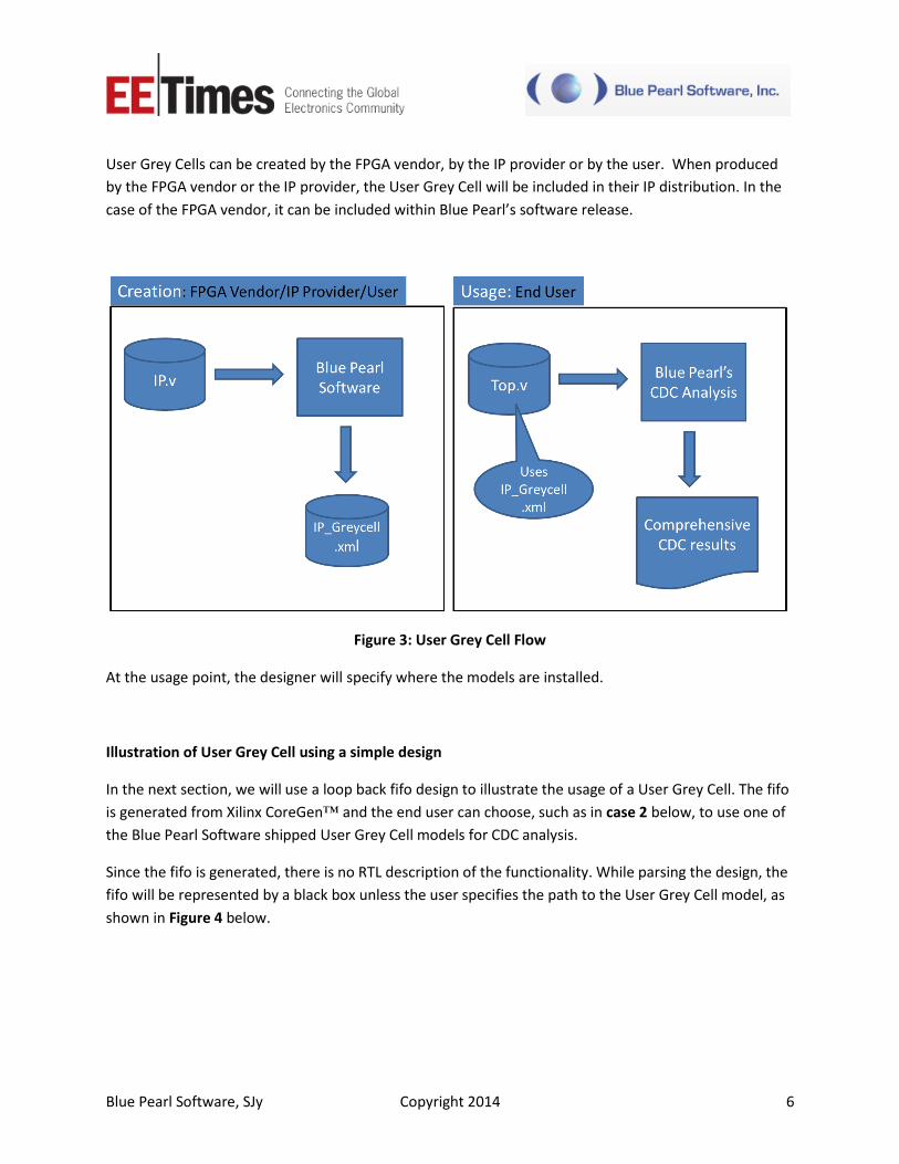
User Grey Cell Flow
A User Grey Cell flow can fill many of the holes left by black boxes. But first, let’s differentiate between
User Grey Cell creation and User Grey Cell usage, as shown in Figure 3 below.
Blue Pearl Software, SJy Copyright 2014 6
User Grey Cells can be created by the FPGA vendor, by the IP provider or by the user. When produced
by the FPGA vendor or the IP provider, the User Grey Cell will be included in their IP distribution. In the
case of the FPGA vendor, it can be included within Blue Pearl’s software release.
Figure 3: User Grey Cell Flow
At the usage point, the designer will specify where the models are installed.
Illustration of User Grey Cell using a simple design
In the next section, we will use a loop back fifo design to illustrate the usage of a User Grey Cell. The fifo
is generated from Xilinx CoreGen™ and the end user can choose, such as in case 2 below, to use one of
the Blue Pearl Software shipped User Grey Cell models for CDC analysis.
Since the fifo is generated, there is no RTL description of the functionality. While parsing the design, the
fifo will be represented by a black box unless the user specifies the path to the User Grey Cell model, as
shown in Figure 4 below.
Blue Pearl Software, SJy Copyright 2014 7
Figure 4: Specifying the path to the User Grey Cell model
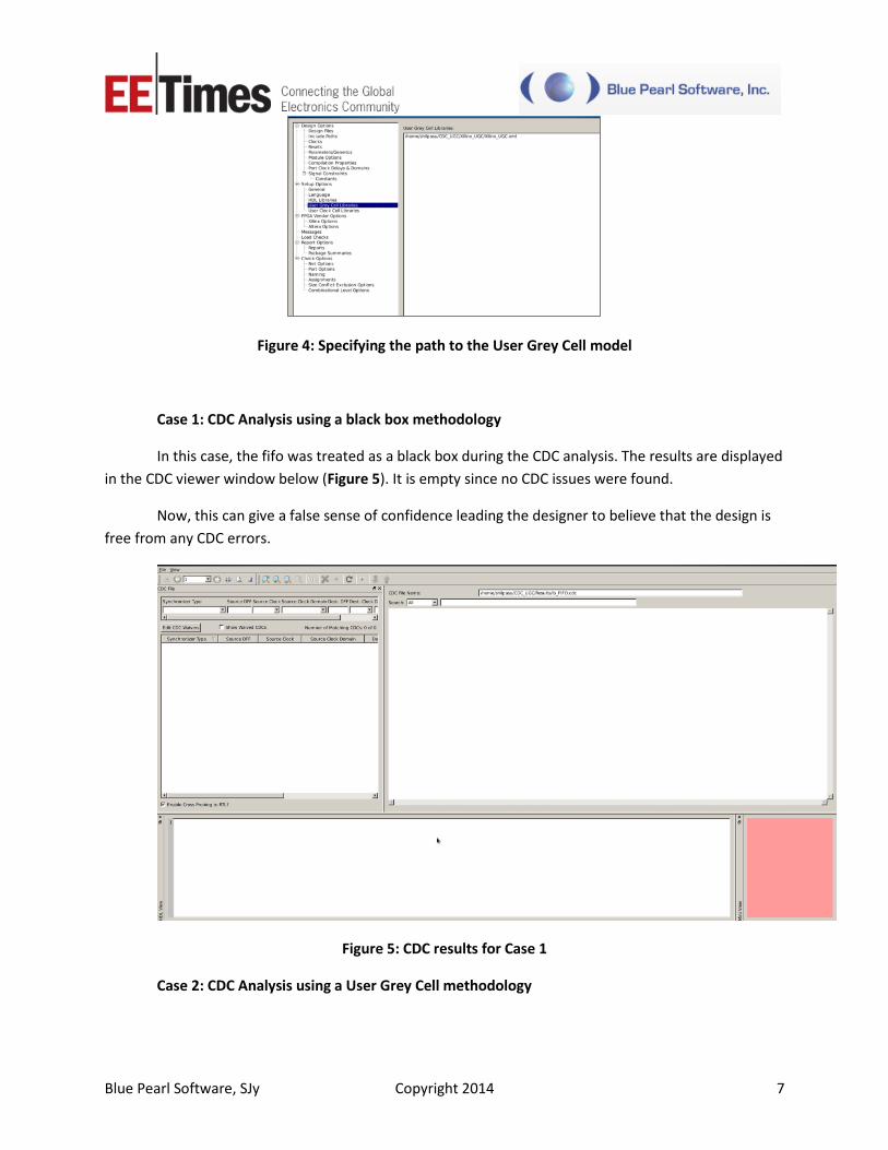
Case 1: CDC Analysis using a black box methodology
In this case, the fifo was treated as a black box during the CDC analysis. The results are displayed
in the CDC viewer window below (Figure 5). It is empty since no CDC issues were found.
Now, this can give a false sense of confidence leading the designer to believe that the design is
free from any CDC errors.
Figure 5: CDC results for Case 1
Case 2: CDC Analysis using a User Grey Cell methodology

Blue Pearl Software, SJy Copyright 2014 8
In this particular case, the end user created a User Grey Cell model for the fifo as shown below.
Figure 6: User Grey Cell for the generated FIFO
This time the user indicated that a User Grey Cell exist for the fifo and then ran the CDC analysis.
The results in the CDC Viewer (Figure 7) are quite different. Here we see six CDC violations.
Moreover, we can check if the fifo is connected properly in the design. One of the CDC violations
in this example is due to the “full” signal not being synchronized with “rdclk” in the “read” domain.
Figure 7: CDC results for Case 2

Blue Pearl Software, SJy Copyright 2014 9
What’s the Take Away?
Designers who are frustrated with or who have been burned by unexplained chip failures caused by
metastability issues now have an alternative to the black box method of verification. Using Blue Pearl’s
relatively easy to use User Grey Cell methodology, the chances of missing the metastability-causing CDC
problems can be significantly reduced.