reduced rating dynamic voltage … rating dynamic voltage restorer with energy optimized by using...
TRANSCRIPT

International Research Journal of Engineering and Technology (IRJET) e-ISSN: 2395 -0056
Volume: 03 Issue: 06 | June-2016 www.irjet.net p-ISSN: 2395-0072
© 2016, IRJET ISO 9001:2008 Certified Journal Page 2375
REDUCED RATING DYNAMIC VOLTAGE RESTORER WITH ENERGY
OPTIMIZED BY USING FUZZY LOGIC CONTROLLER
M.Madhuri1, K.Nagabhushanam2
1 PG Scholar, Department of EEE, JNTU Anantapur, Andhra Pradesh, India 2 Lecturer, Department of EEE, JNTU Anantapur, Andhra Pradesh, India ---------------------------------------------------------------------***-------------------------------------------------------------------- Abstract— In this paper, reduced rating dynamic voltage restorer(DVR) with the fuzzy logic controller is analyzed by using Tolal Harmonic distortions (THDs) .Different voltage injection schemes are used to reduce the rating of voltage source inverter(VSC)used in DVR. The reference load voltage is assessed utilizing the unit vectors. Synchronous reference frame theory is used for transformation of voltages. A battery storage system is used for energy optimization. The problem associated with conventional PI controller is eliminated by the fuzzy logic controller. voltage sag, swell, and harmonics are compensated using a reduced rating DVR. This paper presents the modeling and simulation of DVR using MATLAB/SIMULINK.
Keywords— power quality issues, dynamic voltage restorer , SRF theory, voltage harmonics, voltage sag
&swell, fuzzy logic controller, THD.
1. INTRODUCTION In recent, power quality issue is a major problem in a distribution system[1], due to expanded utilization of nonlinear loads and process industries .Because of these nonlinear loads power quality issues like voltage harmonics in supply voltage ,voltage sags& swells are arise. Custom power devices like dynamic voltage restorer(DVR),distribution static compensators (DSTATCOM) and unified power quality conditioner (UPQC) are raised to improve power quality problems. These custom power devices are introduced at the consumer point to meet the power quality issues. A dynamic voltage restorer can compensate the load voltage from the problems like voltage harmonics, voltage sags& swells.
Voltage sags & swells and voltage harmonics[9] are always not possible to eliminate because of finite clearing time of the fault. If these are not eliminated the device may damage or the entire system may collapse. so we have to protect each and every component of the system by a protective device. If it is done, the power system network may become bulky and complicated. So another solution to this provides an uninterrupted power supply(UPS) for longer power interruptions and a DVR is placed on the incoming supply for shorter power interruptions. The design of self -supported DVR is discussed in [6].
2. CONSTRUCTION AND OPERATION OF DVR: The basic circuit of DVR connected system is shown in fig-1.DVR is connected between supply and critical load through the series injection transformer. DVR consists of a voltage source inverter(VSC).DVR can inject the voltage such that load voltage is in constant magnitude and supply voltage is not constant.
Fig-1:Basic circuit of DVR
Phasor diagram of the voltage injection schemes[4] is shown in fig-2. VL is the voltage across the critical load when voltage sag occur. During the voltage sag, voltage is reduced to VS with a phase angle θ. Now DVR can inject the voltage such that load voltage is maintained constant. From the diagram, Vinj1 is the injection voltage of DVR such that it is in phase with the supply voltage.Vinj2 is the

International Research Journal of Engineering and Technology (IRJET) e-ISSN: 2395 -0056
Volume: 03 Issue: 06 | June-2016 www.irjet.net p-ISSN: 2395-0072
© 2016, IRJET ISO 9001:2008 Certified Journal Page 2376
injection voltage such that load voltage magnitude remains constant but leads the supply voltage VS by a small angle. Vinj3 is the injected voltage at which load voltage remains constant.Vinj4 is the injected voltage where the voltage is in quadrature with the current. In this case, self-supported DVR is used, in the first case minimum possible rating is achieved, then DVR is operated with a battery storage system.
Fig-2.phasor diagram of voltage injection schemes.
The three-phase connected DVR system is shown in fig-3.A three-phase supply is connected to the three-phase critical load through the series injection transformers. Lr and Cr represent the filter components to eliminate ripples in the injected voltage. A three leg voltage source converter with insulated–gate bipolar transistors (IGBT)is used in DVR and a battery storage system is connected to its DC bus.
Fig-3:Three phase connected DVR system
3. CONTROL OF DVR USING PI CONTROLLER
DVR can compensate the harmonics or voltage sags by injecting or absorbing the real or reactive power. when injected voltage and current is 90 degrees out of phase the compensation is made by injecting reactive power, then self -supported DVR is used. when voltage and current are in the same phase, then compensation is made by using real power ,then DVR is operated with battery storage .
3.1 control of DVR with in-phase injection voltage using Battery energy storage system( BESS)
The control block of DVR with in-phase injection scheme with BESS is shown in fig-4.The voltage, at PCC Vs and the load terminal voltage VL , are sensed for deriving IGBT gate signals. Load voltages, reference load voltages, and the voltage at PCC Vs are converted into rotating reference frame using park’s transformation.
DVR voltages are given by VDd=Vsd- VLd
VDq= VSa- VLq
The reference load voltages are obtained in rotating reference frame by
V*Dd=V*Sd-VLd
V*Dq=V*Sq-VLq
The error between the reference and actual DVR voltages is regulated using two proportional-integral controllers. The reference DVR voltages are given by
The actual and reference DVR voltages are given to pulse width modulation(PWM) controller to generate gating signals to a VSC of the DVR.

International Research Journal of Engineering and Technology (IRJET) e-ISSN: 2395 -0056
Volume: 03 Issue: 06 | June-2016 www.irjet.net p-ISSN: 2395-0072
© 2016, IRJET ISO 9001:2008 Certified Journal Page 2377
Fig-4:Control block of the DVR with BESS which uses the SRF method of control.
3.2 control of self -supported DVR
Fig-5:control block of self- supported DVR
The control block of self- supported DVR system is shown in fig-5. Low pass filter is used to eliminate ripples in the injected voltage. The d-axis and q -axis components are given by Vd= Vddc +Vdac
Vq=Vqdc +Vqac
To maintained dc bus voltage of capacitor which is connected to self -supported DVR system ,a PI controller is used at the dc bus voltage of the DVR.
Vcap(n) = Vcap(n-1)+ Kp1(Vde(n)-Vde(n-1)+ Ki1Vdc(n)
where Vde(n)-Vde(n-1) is the error between the reference V*
dc and sensed dc voltages Vdc at the nth sampling instant.Kp1 and Ki1 are the proportional and integral gains of the dc bus voltage PI controller.
The d-axis load voltage is given by V*d=Vddc- Vcap
VL=(2/3)1/2(vLa2 + vLb
2 +vLc2)1/2
PI controller is used to regulating the reference value
Vqr(n) =vqr(n-1)+Kp2(vte(n)-vte(n- 1))+Ki2vtc(n )
Here Vte(n)=V*L –VL(n) , Kp2 and Ki2 are the proportional and
integral gains of the PI controller.
The reference load quadrature axis voltage is given by
V*q=Vqdc+Vqac
The reference load voltages are obtained from park’s transformation. The gating signals are given to VSC of the DVR.
3.3 Energy Storage Unit:
Various devices like Flywheels, Lead acid batteries, Super-Capacitors and Superconducting Magnetic energy storage system can be used as energy storage devices. These devices can provide the desired real power through the energy storage units during voltage sag condition. The amount of active power supplied by the energy storage device is an important one, as it decides the compensation ability of DVR. Among all energy storage units, lead batteries are popular because of their high response during charging and discharging. The discharge rate mainly depends on the chemical reaction rate of the battery. Based on this discharge rate the available energy inside the battery is determined .
3.4 Total harmonic distortion
THD is defined as the ratio of root mean square value of all harmonic components of a signal to the fundamental component. Nonlinear loads are the main cause of harmonic voltages, because of these harmonics power quality problems may occur in a power system result in heating in the equipment and conductors, torque pulsation in motors and misfiring in variable speed drive. So we have to eliminate these harmonics. Harmonics may increase the current in the power system network. This is mainly in case of the 3rd harmonic component, which causes a sudden increase in zero sequence current, and increases the current in the neutral conductor. Harmonics have the frequencies that are integral multiples of fundamental frequencies of a signal. If the fundamental frequency is 50 Hz ,the 3rd and 5th harmonics are 150Hzs and 250Hzs respectively. so we have to maintain the THD value as low as possible.

International Research Journal of Engineering and Technology (IRJET) e-ISSN: 2395 -0056
Volume: 03 Issue: 06 | June-2016 www.irjet.net p-ISSN: 2395-0072
© 2016, IRJET ISO 9001:2008 Certified Journal Page 2378
4. FUZZY LOGIC CONTROLLER
The problems associated with traditional PI control are solved by using improved fuzzy logic controller. PI controllers are difficult to control because of tuning method. The advantage of the fuzzy logic controller is to achieve good operation by the variation of parameters. The primary graphical user interface(GUI)is shown in fig-6.GUI guide you through the movements of fuzzy prompting system plot. The FIS Editor handles the strange state issues for the system.
Fig-6:The Primary GUI Tools of the Fuzzy Logic Toolbox
The fuzzy logic is the relative importance of exactness .
We can use the Fuzzy Logic Toolbox programming with MATLAB specific figuring programming as an instrument for dealing with issues with the soft method of reasoning. Better performance can be observed using the fuzzy logic controller for power quality improvement. The instability can be eliminated by using the fuzzy tool . Fuzzy Logic Controller (FLC), approaching the human reasoning that makes use of the uncertainty, tolerance, and fuzziness in the decision- making process and manages to propose a very satisfactory operation, without the need of a complex mathematical model of the system, just by integrating the human knowledge with fuzzy rules. In addition, it has essential abilities to deal with inaccurate or noisy data; thus it is able to develop its control capability to those operating conditions where linear control techniques fail i.e., large parameter variations. Conceptually, fuzzy logic controllers are very simple as shown fig-7.
Fig.-7 Structure of Fuzzy Logic Controller
5.SIMULATION MODEL
Fig -8.simulation model of DVR connected system

International Research Journal of Engineering and Technology (IRJET) e-ISSN: 2395 -0056
Volume: 03 Issue: 06 | June-2016 www.irjet.net p-ISSN: 2395-0072
© 2016, IRJET ISO 9001:2008 Certified Journal Page 2379
6.RESULTS
Fig-9. The Performance of DVR during harmonics in supply voltage.
Fig-9. shows the compensation of harmonics in supply voltage. At 0.2 s harmonics occur up to 5 cycles.DVR is injected a compensation voltage to the system and load voltage is regulated to a constant amplitude
Fig-10. Source voltage ,DVR voltage,Load voltage under
Voltage Sag
Fig-10. shows the dynamic performance of the system
under voltage sag. At 0.2 s voltage sag occur up to 5
cycles.DVR is injected a compensation voltage to the
system and load voltage is regulated to a constant
amplitude.
Fig-11. Source voltage ,DVR voltage,Load voltage under
Voltage Sag
Fig-11. shows the dynamic performance of the system
under voltage swell. At 0.5s voltage swell occur up to 5
cycles. DVR is injected a compensation voltage to the
system and load voltage is regulated to a constant
amplitude.
Fig-12. source voltage ,DVR voltage,load voltage under
voltage sag and swell.
International Research Journal of Engineering and Technology (IRJET) e-ISSN: 2395 -0056
Volume: 03 Issue: 06 | June-2016 www.irjet.net p-ISSN: 2395-0072
© 2016, IRJET ISO 9001:2008 Certified Journal Page 2380
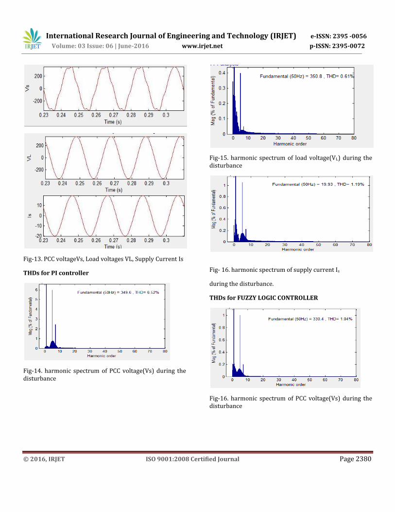
Fig-13. PCC voltageVs, Load voltages VL, Supply Current Is
THDs for PI controller
Fig-14. harmonic spectrum of PCC voltage(Vs) during the disturbance
Fig-15. harmonic spectrum of load voltage(VL) during the disturbance
Fig- 16. harmonic spectrum of supply current Is
during the disturbance.
THDs for FUZZY LOGIC CONTROLLER
Fig-16. harmonic spectrum of PCC voltage(Vs) during the disturbance
International Research Journal of Engineering and Technology (IRJET) e-ISSN: 2395 -0056
Volume: 03 Issue: 06 | June-2016 www.irjet.net p-ISSN: 2395-0072
© 2016, IRJET ISO 9001:2008 Certified Journal Page 2381
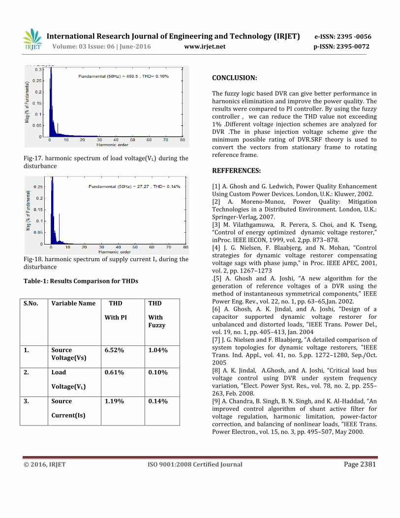
Fig-17. harmonic spectrum of load voltage(VL) during the disturbance
Fig-18. harmonic spectrum of supply current Is during the disturbance
Table-1: Results Comparison for THDs
S.No. Variable Name THD
With PI
THD
With Fuzzy
1. Source Voltage(Vs)
6.52% 1.04%
2. Load
Voltage(VL)
0.61% 0.10%
3. Source
Current(Is)
1.19% 0.14%
CONCLUSION: The fuzzy logic based DVR can give better performance in harnonics elimination and improve the power quality. The results were compared to PI controller. By using the fuzzy controller , we can reduce the THD value not exceeding 1% .Different voltage injection schemes are analyzed for DVR .The in phase injection voltage scheme give the minimum possible rating of DVR.SRF theory is used to convert the vectors from stationary frame to rotating reference frame.
REFFERENCES:
[1] A. Ghosh and G. Ledwich, Power Quality Enhancement Using Custom Power Devices. London, U.K.: Kluwer, 2002. [2] A. Moreno-Munoz, Power Quality: Mitigation Technologies in a Distributed Environment. London, U.K.: Springer-Verlag, 2007. [3] M. Vilathgamuwa, R. Perera, S. Choi, and K. Tseng, “Control of energy optimized dynamic voltage restorer,” inProc. IEEE IECON, 1999, vol. 2,pp. 873–878. [4] J. G. Nielsen, F. Blaabjerg, and N. Mohan, “Control strategies for dynamic voltage restorer compensating voltage sags with phase jump,” in Proc. IEEE APEC, 2001, vol. 2, pp. 1267–1273 .[5] A. Ghosh and A. Joshi, “A new algorithm for the generation of reference voltages of a DVR using the method of instantaneous symmetrical components,” IEEE Power Eng. Rev., vol. 22, no. 1, pp. 63–65,Jan. 2002. [6] A. Ghosh, A. K. Jindal, and A. Joshi, “Design of a capacitor supported dynamic voltage restorer for unbalanced and distorted loads, ”IEEE Trans. Power Del., vol. 19, no. 1, pp. 405–413, Jan. 2004 [7] J. G. Nielsen and F. Blaabjerg, “A detailed comparison of system topologies for dynamic voltage restorers, ”IEEE Trans. Ind. Appl., vol. 41, no. 5,pp. 1272–1280, Sep./Oct. 2005 [8] A. K. Jindal, A.Ghosh, and A. Joshi, “Critical load bus voltage control using DVR under system frequency variation, ”Elect. Power Syst. Res., vol. 78, no. 2, pp. 255–263, Feb. 2008. [9] A. Chandra, B. Singh, B. N. Singh, and K. Al-Haddad, “An improved control algorithm of shunt active filter for voltage regulation, harmonic limitation, power-factor correction, and balancing of nonlinear loads, ”IEEE Trans. Power Electron., vol. 15, no. 3, pp. 495–507, May 2000.

International Research Journal of Engineering and Technology (IRJET) e-ISSN: 2395 -0056
Volume: 03 Issue: 06 | June-2016 www.irjet.net p-ISSN: 2395-0072
© 2016, IRJET ISO 9001:2008 Certified Journal Page 2382
.
BIOGRAPHIES
M.Madhuri currently pursuing M.Tech Electrical Power Systems at JNTUA College Of Engineering and Technology Anantapur, Andhra Pradesh. Area area of interest is Power Systems.
K.Nagabhushanam, working as a lecturer in department of EEE, JNTU college of Engineering and Technology
Anantapur, AndhraPradesh.

International Research Journal of Engineering and Technology (IRJET) e-ISSN: 2395 -0056
Volume: 03 Issue: 06 | June-2016 www.irjet.net p-ISSN: 2395-0072
© 2016, IRJET ISO 9001:2008 Certified Journal Page 2383