reduced-temperature solid oxide fuel cell based on ysz thin … · 2013-03-29 · l36 j....
TRANSCRIPT
J. Electrochem. Soc., Vol. 144, No. 3, March 1997 © The Electrochemical Society, Inc.
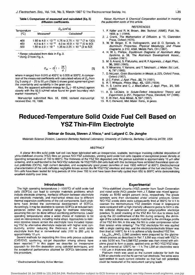
Table I. Comparison of measured and calculated (Eq. 5)diffusion coefficients.
Temperature Dff (cm2/s)(°C) Measureda Calculated b
400 1.95 to 4.0 x 10-'0 1.75 to 3.75 x 10-'0° (7 to 13D)450 4.3 to 8.1 x 10-' ° 6.0 to 10.8 x 10-' (5 to 9D)500 1.55 to 2.9 x 10⁻⁹ 1.35 to 2.25 x 10⁻⁹ (3 to 5D)
a Range calculated from data in Fig. 3.b Using D from Fig. 4.
Deft = D 1 + 2k [5]
where k ranged from 0.015 at 400°C to 0.005 at 500°C. A compar-ison of the measured coefficients with calculated values of De, fromEq. 5 using d = 25 to 50 pem (Table I) shows good agreement giventhe uncertainty and variability in the grain size.
Also, the apparent activation energy for De, (-85 kJ/mol) agreesclosely with the 92.5 kJ/mol value found for grain boundary etchmarker movement."
Manuscript submitted Nov. 18, 1996; revised manuscriptreceived Dec. 19, 1996.
Kaiser Aluminum & Chemical Corporation assisted in meetingthe publication costs of this article.
REFERENCES1. F Keller and R. H. Brown, Met. Technol. (AIME), Publ. No.
1659, p.1 (1944).2. J. Crank, The Mathematics of Diffusion, p. 15, Clarendon
Press, Oxford (1975).3. W. W. Binger, E. H. Hollingsworth, and D. O. Sprowls, in
Aluminum: Properties, Physical Metallurgy and PhaseDiagrams, p. 210, ASM, Metals Park, OH (1967).
4. H. W. L. Phillips, Equilibrium Diagrams of Aluminum AlloySystems, p. 58, The Aluminum Development Assoc.,London (1961).
5. M. S. Anand, S. P. Murarka, and R. R Agarwala, J. Appl. Phys.,36, 3860 (1965).
6. Y. Minamino, Y. Yamane, and T. Takahashi, J. Mater. Sci. Lett.,4, 797 (1985).
7. D. McLean, Grain Boundaries in Metals, p. 225, Oxford Press,Oxford (1957).
8. J. C. Fisher, J. Appl. Phys., 22, 74 (1951).9. R.T. Whipple, Philos. Mag., 45, 1225 (1954).
10. H. S. Levine and C. J. MacCallum, J. Appl. Phys., 31, 595(1960).
11. A. D. LeClaire, in Solute-Defect Interactions: Theory andExperiment, p. 251, Pergamon Press, Elmsford, NY (1986).
12. E.W. Hart, Acta Metall., 5, 597 (1957).13. R. C. Dorward, Met. Mater. Trans., In press.
Reduced-Temperature Solid Oxide Fuel Cell Based onYSZ Thin-Film Electrolyte
Selmar de Souza, Steven J. Visco,* and Lutgard C. De JongheMaterials Science Division, Lawrence Berkeley National Laboratory University of California, Berkeley, California 94720, USA
ABSTRACT
A planar thin-film solid oxide fuel cell has been fabricated with an inexpensive, scalable, technique involving colloidal deposition ofyttria-stabilized zirconia (YSZ) films on porous NiO-YSZ substrates, yielding solid oxide fuel cells capable of exceptional power density atoperating temperatures of 700 to 800°C. The thickness of the YSZ film deposited onto the porous substrate is approximately 10 Rim aftersintering, and is well bonded to the NiO/YSZ substrate. Ni-YSZ/YSZ/LSM cells built with this technique have exhibited theoretical open-cir-cuit potentials (OCPs), high current densities, and exceptionally good power densities of over 1900 mW/cm2 at 800°C. Electrochemicalcharacterization of the cells indicates negligible losses across the Ni-YSZ/YSZ interface and minor polarization of the fuel electrode. Thin-film cells have been tested for long periods of time (over 700 h) and have been thermally cycled from 650 to 800°C while demonstratingexcellent stability over time.
IntroductionThe high operating temperatures (-1000°C) of solid oxide fuel
cells (SOFCs) can lead to complex materials problems whichinclude electrode sintering, inerfacial diffusion between electrolyteand electrode materials, and mechanical stress due to differentthermal expansion coefficients of the cell components. Such prob-lems have limited the commercial development of SOFCs.Accordingly, it may be desirable to operate SOFCs at reduced tem-peratures (within the practical range for methane reforming),assuming this can be done without sacrificing performance. Loweroperating temperatures allow a wider choice of materials to beused as interconnects, including metal alloys. Approaches to mini-mize resistive losses across the electrolyte have included replac-ing YSZ by alternative electrolyte materials with higher ionic con-ductivity, and/or reducing the thickness of the solid oxideelectrolyte from that in conventional cells (100 to 200 plm) toapproximately 10 Lim.
Several methods for depositing thin films onto porous subtrates(CVD/EVD, sputtering, sol-gel deposition among others) havebeen reported. 5 In this paper we describe an inexpensiveapproach for thin-film deposition using colloidal techniques, andthe exceptional performance attained for SOFCs fabricated withthis procedure.
* Electrochemical Society Active Member.
ExperimentalYttria-stabilized zirconia (YSZ) powder from Tosoh Corporation
and nickel oxide (NiO) powder from J. T. Baker was mixed approx-imately as 50/50 weight percent (w/o), respectively. The anodepowders were then compacted under uniaxial pressure. GreenNiO-YSZ anode disks were subsequently fired at 950°C for 4 h tocoarsen the microstructure. YSZ powders mixed in isopropanolwere sonicated with a high intensity ultrasonic probe to form a sta-ble colloidal dispersion of submicron polycrystalline electrolyepowders. To avoid cracking of the YSZ thin film due to stress builtup by the 2D confinement of the film during sintering, the shrink-age of the substrate was carefully matched to the shrinkage profileof the YSZ thin film. In this way, the film is under compression ratherthan tension while sintering.6 The YSZ electrolyte film was appliedwith a single casting step, and the electrolyte/electrode bilayer wasthen fired at 1400°C for 4 h to achieve a fully densified YSZ film.
La085Sr015MnO3 (LSM) powders were prepared by the glycine-nitrate process as described in Ref. 7. LSM was mixed with YSZ ina ratio 50/50 w/o. The LSM/YSZ powder was then mixed with eth-ylene glycol to form a paste, applied onto an NiO-YSZ/YSZ bilay-er, and sintered at 1250°C for -1 h.The LSM air electrodes were-100 pLm in thickness after sintering.
Platinum mesh was used as the current collector for both theLSM air electrode and the Ni-cermet fuel electrode. Two wires werespot-welded to each current collector so that fuel cell potentialscould be measured at the noncurrent carrying leads.
L35
Downloaded 16 Jul 2009 to 131.243.54.244. Redistribution subject to ECS license or copyright; see http://www.ecsdl.org/terms_use.jsp

L36 J. Electrochem. Soc., Vol. 144, No. 3, March 1997 The Electrochemical Society, Inc.
ZrO,or ALO Soal
- LSMPtlcnds H2+3v%HO AIR
Pt contacts
Referem.eNi-ccrmct electrode
YSZ film
Ceramic adhesives were used to fix and seal the fuel cell/currentcollector structure to an alumina or zirconia tube which was usedas a fuel cell testing assembly (Fig. 1). Hydrogen saturated withH20 at room temperature was used as fuel. Air was used as oxi-dant and was supplied to the cathode by ambient flow. Since theH2/H20 stream was not preheated, there was some cooling of thefuel cell relative to the furnace temperature. A platinum referenceelectrode was bonded onto the thin electrolyte film, at several mil-limeters from the working electrode on the air side. Current inter-rupt and/or impedance spectroscopy was used to measure theohmic resistance of the fuel cell.
Results and DiscussionThe performance of SOFCs, H2 + 3 volume percent (v/o) H20,
Ni-YSZ/YSZ/La0855r05MnO3, air, were evaluated under currentcontrol. Figure 2 shows current-voltage (l-t' curves for a single celltested at 800°C. The maximum power density achieved was 1935mW/cm2 at a current density of 4.5 A/cm2 and cell voltage of 0.43V (LBNL cells typically exceed 1.8 W/cm2 at 800°C). This resultillustrates the exceptional performance achievable for YSZ thin-filmelectrolyte-based SOFCs operating at reduced temperatures. Cellsof this type have been operated at power densities of 800 mW/cm2for more than 700 h with no detectable loss in performance.
Figure 3 shows the voltage drop vs. current for a thin-film cell.The total voltage drop was separated into ohmic and nonohmiccontributions by the current interrupt method. The use of a refer-ence electrode allowed separation of anodic and cathodic contri-butions to cell polarization. The YSZ IR drop is estimated from theknown conductivity and thickness of the electrolyte (10 p.m). Ascan be seen from Fig. 3, even at very high current denesities, thevoltage drop due to a 10 p.m YSZ electrolyte film is almost negligi-ble. The remainder of the ohmic drop is probably due to contactresistance at the LSM/YSZ interface as well as minor lossesacross the current collectors. The ohmic loss across the Ni-YSZ/YSZ interface is essentially negligible. The polarization of theelectrodes (ii. + i) account for about 40% of the total voltagedrop. The cathodic polarization (,) was larger than the anodicpolarization (i) which was almost negligible for current densitiesbelow 2.0 A/cm2. The YSZ electrolyte JR drop represents about18% of the total voltage drop.
0 1000 2000 3000 4000 5000 6000 7000
Current Density (mA/cm2)
Fig. 2. I-V characteristics of a (H2 + yb H20), Ni-YSZ/YSZILSM, (air) fuel cell at 800°C.
0.2
0.00 1000 2000 3000 4000 5000 6000 7000
Current Density (mAicm2)Fig. 3. Separation of cell polarization components by cur-
rent interrupt techniques; total resistance calculated from theohmic drop (IR) of the cell; i, cathode polarization; i, anodepolarization, and the YSZ electrolyte IR drop.
Figures 4 and 5 show the cross sections of the Ni-cermetlYSZJPt and Ni-YSZIYSZ/LSM fuel cell structures, which have beenreduced in hydrogen at 800°C. It is observed that the thin-YSZelectrolyte film is uniformly continuous, pore free, and well adheredto the porous Ni-YSZ fuel electrode. The Ni-cermet is highly uni-form with an even distribution of pores and good particle to parti-cle contact. The LSM electrode (Fig. 5) appears to have a less uni-form structure when compared to the Ni-cermet which mayaccount for the larger cathodic polarization relative to anodic polar-ization over most of the I-V curve.
Fig. 4. Scanning electron micrograph of a Ni-cermet/YSZ/Ptthin-film fuel cell cross section. YSZ electrolyte film is 9 mthick. NiO-YSZ was reduced in situ with H2/H20 at 800°C toyield final Ni-YSZ cermet structure.
Fig. 1. Fuel cell testing assembly diagram.
1.2
1.0
0.8
0.6
0.4
>CD
cw0a-
Cathodic Polarization plusohmic drop of LSM and YSZ
0>
C
00a,0
1.1
1.0
0.9
0.8
0.7
0.6
0.5
0.4
0.3
0.2
0.1
0.0 .,.
2000
1800
1600 c-1400
L1200
1000
800
-600
-400
200
L0
Downloaded 16 Jul 2009 to 131.243.54.244. Redistribution subject to ECS license or copyright; see http://www.ecsdl.org/terms_use.jsp

J. Elect rochem. Soc., Vol. 144, No.3, March 1997 The Electrochemical Society, Inc. L37
ConclusionsA highly successful procedure has been developed which allows
deposition of thin-film ceramics on highly porous substrates. The
methodology is inexpensive and scalable. Thin-film SOFCs fabri-cated using these techniques demonstrate performances of closeto 2 W/cm2 at 800°C. Current interrupt techniques indicate themajority of the voltage loss at high current density is due to ohmiclosses, most likely associated with cathode/electrolyte contactresistance (0.1 i cm2). The exceptional performance of the thin-film SOFC5 implies that reduced temperature operation is possiblewhile still maintaining high power density.
AcknowledgmentThis research was supported by the Laboratory Technology
Research Program (ER-LTR), Office of Computational andTechnology Research, U.S. Department of Energy under a CRADA(Cooperative Research and Development Agreement) betweenErnest Orlando Lawrence Berkeley National Laboratory (BerkeleyLab) and The Electric Power Research Institute (EPRI), Palo Alto,CA 94303, under U.S. DOE Contract DE-ACO3-76SF00098.
Manuscript submitted Sept. 23, 1996; revised manuscriptreceived Oct. 20, 1996.
Lawrence Berkeley National Laboratory assisted in meeting thepublication costs of this article.
REFERENCES
1. N. W. Minh, J. Am. Ceram. Soc., 76, 563 (1993).2. A. Negishi, K. Nozaki, and T. Ozawa, Solid State lonics, 3/4,
443 (1981).3. A. 0. lsenberg, ibid., 3/4, 431 (1981).4. T.Setogushi,T.lnou, H.Takebe, K. Eguchi, K. Morinaga, and H.
Arai, This Journal, 139, 2875 (1992).5. U.B.Pal and S. C. Singhal, ibid., 137, 2937 (1990).6. 5. J. Visco, L.-S. Wang, S. Souza, L. C. De Jonghe, Mater. Res.
Soc. Symp. Proc., 369, 683 (1995).7. L. A. Chick. L. R. Pederson, G. D. Maupin, J. L. Bates, L. E.
Thomas, and G. I. Exartos, Mater. Lett., 10, 6 (1990).
Highly Selective Chemical Etching of Si vs. Si_GeUsing NH4OH Solution
FengWang,*Yi Shi,Jianlin Liu,Yang Lu,Sulin Gu,andYoudou ZhengDepartment of Physics and Institute of Solid State Physics, Nanjing University, Nanjing 210093, China
ABSTRACT
Highly selective chemical etching of Si vs. epitaxial Si1 Ge in NH4OH solution has been investigated. It was found the selectivity wasbetter than 80:1 even for a Si09Ge0, in 10 weight percent(w/o) NH4OH at 75°C. As the fraction xof Ge was increased, higher selectivity wasobtained due to the decrease of the etch rate of the Si - The achievement of the excellent selectivity in a Si/Si Ge/Si heterostructurewas clearly demonstrated by scanning electron microscopy. Surfaces of etched Si1, ,Ge, samples were analyzed using x-ray photoelectronspectroscopy. The high etch selectivity obtained in NH4OH is essentially due to a passivation-film effect at the Si1Ge surface.
IntroductionSelective chemical etching of Si or Si1 Ge,, has become a key
technique in the fabrication of Si1 Ge/Si heterojunction devices14and new kinds of structures.5'7 In the fabrication process of the het-erojunction device employing thin Si or Si1Ge layers, for exam-ple, it is often necessary to contact to buried Si or Si1 Ge layers.To make contact to buried Si,.,,Ge, layers one needs to etch Siand vice versa. Thin film bond and etchback silicon on insulator(BESOI) of good quality was fabricated using a strained Si07Ge03as an etch-stop layer. An important process of the fabrication wasto selectively etch Si over the Si0 7Ge53. Recently, we proposedand successfully fabricated Si quantum wires based on selectivelyremoving Si1 Ge, from a Si/Si1 AGe, trench array.7
During the last several years, therefore, the characteristics ofseveral chemical wet etchants for selectively etching Si1Ge
Electrochemical Society Student Member.
and/or Si on Si1 Ge/Si heterostructures have been investigat-ed.5"1 Among them, two aqueous etchants to selectively etch Siover Si Ge, were reported. One is the etchant composed ofKOH:K2Cr2O7:propanol:H2O. 6,10 A selectivity of 40:1 was obtainedrecently in etching Si over B-doped Si07Ge03, but it is completelyisotropic and requires the use of a hard mask.1° Another is the mix-ture of ethylenediamines, pyrocatechol, and water (EPW), whichwas reported to etch Si over Si/Si1 ,Ge,, (x> 0.2) with a high selec-tivity.11 For a practical application, however, a selective chemicaletching should be compatible with silicon integrated circuit (IC)processes. As a result, IC-compatible, nontoxic, anisotropic, sim-ple, and highly selective etchants become important for processinghigh performance devices. Solutions based on ammonium hydrox-ide-water mixtures have been widely used in Si IC processes.12Koyama et al. investigated the etch characteristics of Si Ge, alloyin an ammoniac wet cleaning solution NH4OH:H2O2:H2O. It wasobserved that the etch rate of Si .,Ge was in the order of
I. ' '
16.Ni—Cermet
...'.... '..vFig. 5. SEM micrograph showing cross section of a Ni-
Cermet/YSZ/LSM thin-film fuel cell that was thermally cycledand tested over 400 h.
Downloaded 16 Jul 2009 to 131.243.54.244. Redistribution subject to ECS license or copyright; see http://www.ecsdl.org/terms_use.jsp