reducing free play in an automotive steering system · project number: cab-mqp-0619 reducing free...
TRANSCRIPT

Project Number: CAB-MQP-0619
Reducing Free Play in an Automotive Steering System
A Major Qualifying Project Report
Submitted to the Faculty
of the
Worcester Polytechnic Institute
in partial fulfillment of the requirements for the
Degree of Bachelor of Science in Mechanical Engineering
by
Matthew Fulmer
______________________________
Date: 4 / 30 / 2009 Keywords: 1. steering system 2. free play 3. automobile
Approved: ____________________________ Prof. Christopher A. Brown, Advisor

2
The objective is to design three methods for reducing free play in an automotive
steering system. Existing mechanical steering systems are flawed because they
attempt to use interference to make up for the gradual onset of free play. The current
system combines an increase in steering torque and a reduction in free play in a give-
and-take fashion. This project attempts to work around that problem by coming up with
several design solutions that should reduce the risk of free play. One design involves a
pinion that uses rollers instead of gear teeth, in order to decrease friction. Another
design eliminates the mechanical gearbox and uses hydraulics to steer the vehicle. A
third design is similar to the previous one, but instead employs an electromechanical
servo to operate the system.

3
Table of Contents
Abstract 2
Introduction 4
Objective
Rationale
State-of-the-Art
Approach
Methods 9
Roller Pinion
Hydraulic
Electromechanical
Testing 19
Optimization 24
Discussion 27
Conclusion 29
Bibliography 30

4
Introduction
The objective of this project is to design three methods for reducing free play in
an automotive steering system. This objective is worth pursuing because the issue of
steering system free play is a real problem in the modern automotive industry. It is near
the top of the statistical list of most common steering failures. Strictly speaking,
“steering gear problems” is the number one issue at 1.8 percent, and “free play” comes
in second at 1.7 percent (Limpert 1982). If and when undue steering motion occurs, the
drivability of the vehicle decreases. Whether driving on back roads or on the freeway,
the performance of the vehicle is noticeably reduced. It can also throw the front end out
of alignment, which is hard on the wheel bearings, tires, and suspension. In a worst-
case scenario, reducing free play can even reduce the risk of sudden catastrophic
failure of major steering components. By improving the design and reducing the free
play, the driving experience is thus safer and more precise.
The cause of free play which I focused on was the gearbox, consisting of the
rack and the pinion. When the unit is assembled, the gears are installed tightly to
prevent the early onset of free play. However, this “interference” tactic also increases
the necessary steering torque, which is a disadvantage for the customer. Obviously,
there is a level of give-and-take with this approach, because it eventually contributes to
the exact problem that is being solved in the long run. This issue will be addressed later
in this section.
The current steering system for most vehicles is the rack and pinion, which uses
a mechanical gearbox to steer the vehicle (Nice 2000). Axiomatic design has been
used to form a design decomposition, to allow my later designs to meet the functional

5
requirements of this system. The other purpose of this decomposition is to show that
there is a design flaw which results in parameter coupling, which I will soon discuss.
The decomposition is shown below in Table 1.
Current Steering Device
DP
0:
Rack a
nd p
inio
n s
yste
m
D
P1
: In
cre
ase
inte
rfere
nce
D
P2
: D
ecre
ase
in
terf
ere
nce
D
P3
: In
pu
t d
evic
e
D
P4
: S
tee
rin
g s
ha
ft
D
P5
: R
ack a
nd
pin
ion
D
P6
: T
ie r
od
s
D
P7
: S
tee
rin
g k
nu
ckle
s
FR0: Transmit steering input X
FR1: Regulate free play development
X X O O O O O
FR2: Control steering torque
X X O O O O O
FR3: Accept steering input
O O X O O O O
FR4: Transmit input to system
O O O X O O O
FR5: Convert input to linear motion
O O O O X O O
FR6: Transfer work to wheels
O O O O O X O
FR7: Steer front wheels
O O O O O O X
TABLE 1: Decomposition of a current steering device
In summary, the rotary input to the steering wheel is transferred down the
steering shaft, through several universal joints, and arrives at a pinion gear. The turning
of the pinion pushes the rack gear left and right, which in turn manipulates a set of tie
rods. The tie rods operate the steering knuckles, onto which the front wheels are
mounted. With all of these design parameters in place, the wheels are successfully
steered as a result of the driver’s input (Nice 2001).
To facilitate my design process, a rack and pinion steering system was created in
SolidWorks. Specifically, it provided me with a foundation for additional designs. Some

6
of the dimensions were reverse-engineered from an existing steering unit for real-life
accuracy, such as the size of the housing, size of the rack, and distance between the
rack teeth. From that information, I was also able to determine that the pinion gear had
five teeth, simply by counting the number of rack teeth which were displaced during one
revolution of the steering shaft. In addition, the displacement of the rack told me that I
was dealing with a pinion gear that had a diameter of 0.725 inches including the teeth,
and just 0.425 inches without the teeth. Figure 1 shows an image of the initial model,
with a label for each of the design parameters from the decomposition in Table 1.
FIGURE 1: Current steering device
This model, like all of my models, is an assembly of many separate components.
By constructing the model in this manner, I was able to animate the assembly to see
how it would behave as a real-life steering device. Also, in this and every instance of my
solid models, the blue component represents the stationary “frame” of the vehicle, and
the steering system moves relative to this component. In the following sections, several

7
images of my new designs will be shown. Note that some of these images will show a
tighter view of the system than is shown in Figure 1.
By creating a number of new steering system designs, I am attempting to
decouple steering torque and free play. This problem is illustrated in Figure 2 and
further described below.
FIGURE 2: Coupling issue
This diagram presents two possible scenarios for constructing a current steering
device, both of which are flawed. Case one involves the installation of a tightly-built
gearbox. This feature reduces the risk of an early onset of free play by toughening up
the system right from the beginning. Once free play begins to appear, it will be stifled
by the proximity of the gear teeth, which will minimize it as much as possible. However,
this scenario results in a larger steering torque, which is a disadvantage for the
customer. In addition, free play is likely to occur just as quickly, because the tightness
of the gearbox increases the friction between the gears. This results in a steering
system whose purpose is defeated because of the way it is designed.

8
Case two takes a different approach by designing the gearbox with less extreme
interference. This decision also brings the steering torque back to a relatively normal
level. But once again, free play is no less inevitable. By building a gearbox which may
already contain some gaps, the onset of free play will occur just as quickly as with case
one. My goal is to develop better methods for reducing free play which can decouple
the aforementioned design parameters. My designs focus on this task by addressing the
problems of interference and friction in the gearbox, which are the main causes of free
play and excessive steering torque.

9
Methods
To solve the problem before me, I designed three conceptual methods for
reducing free play. The first design involved modifying several components of the
existing system, without making any large-scale changes. The second and third
designs stemmed from an assumption that the gearbox was the issue, and that it would
make sense to install a different system for moving the linkage.
Roller Pinion Steering System
The first design, instead of a conventional pinion gear, uses a new piece of
hardware in its place. Dubbed the “roller pinion”, the device consists of six rollers which
are installed on a Ferris wheel-style frame. To reduce friction, the rollers ride on the
frame using a set of small cylindrical bearings. The frame mounts directly to the end of
the steering shaft, and the solid shaft “tunnel” provides additional strength for the
component. This sub-assembly of the steering system is shown on the next page in
Figure 4.
The conception of the roller pinion stemmed from the fact that rolling contact
results in an “almost complete elimination of friction” (Esposito 1975). As the roller
pinion is turned by an input from the driver, the rollers are inserted into the rack in the
same manner that a round gear meshes with a straight gear. Accordingly, the rack is
modified to have semi-circular notches in order to accommodate the rollers. An
appropriate set of geometric parameters can be developed to allow the roller pinion to
mesh with the rack without binding up. Also, to make use of the gear housing from the
standard rack and pinion system, the roller pinion is designed to occupy the same

10
space as a conventional pinion gear. The layout of the system is shown below in Figure
3. Two of the design parameters are located outside of the boundaries of the image,
but they are the same as those shown in Figure 1.
FIGURE 3: Roller pinion steering device
FIGURE 4: Roller pinion with rollers installed

11
A major shortcoming of the current steering system is that free play and steering
torque are coupled in a give-and-take fashion. The roller pinion steering system
decouples those features because of the way that the pinion is designed. This
decoupling is represented in the axiomatic design decomposition for this system, shown
below in Table 2.
Roller Pinion Steering Device
DP
0:
Rack a
nd r
olle
r pin
ion
syste
m
D
P1
: F
riction
redu
ctio
n w
ith
rolle
rs
D
P2
: A
dju
st
dia
mete
r of
pin
ion
D
P3
: In
pu
t d
evic
e
D
P4
: S
tee
rin
g s
ha
ft
D
P5
: R
ack a
nd
rolle
r p
inio
n
D
P6
: T
ie r
od
s
D
P7
: S
tee
rin
g k
nu
ckle
s
FR0: Transmit steering input X
FR1: Regulate free play development
X O O O O O O
FR2: Control steering torque
O X O O O O O
FR3: Accept steering input
O O X O O O O
FR4: Transmit input to system
O O O X O O O
FR5: Convert input to linear motion
O O O O X O O
FR6: Transfer work to wheels
O O O O O X O
FR7: Steer front wheels
O O O O O O X
TABLE 2: Decomposition of a roller pinion steering device
The gearbox in this system does not need to be unusually tight, because contact
friction between the gears is not an issue. It only needs to be tight enough to ensure
that the roller pinion and the rack mesh properly. As a result, the steering torque is
merely based on the size of the pinion. With a smaller pinion, the steering torque will

12
decrease, and vice versa. Thus, the steering torque and free play parameters have
successfully been decoupled with this new design.
Hydraulic Steering System
The second steering system design takes a different approach to reducing the
issue of free play. Instead of attempting to reduce the friction in the gearbox, the gears
have been removed altogether. The steering wheel input from the driver is transmitted
electronically to an onboard computer. The computer then converts the information into
electrical signals which operate a pair of hydraulic pumps. In turn, the pumps drive a
pair of hydraulic cylinders which move the rack left and right. From there, the vehicle is
steered using the same tie rods and steering knuckles as the current steering system.
This ensures that the dimensions of the linkage are the same, allowing this and the
current steering system to have identical steering geometry. A solid model of the
hydraulic steering device is shown below in Figure 5. As usual, all of the design
parameters are labeled.
FIGURE 5: Hydraulic steering device

13
To assess the functionality of the hydraulic steering system, a new axiomatic
design decomposition was constructed. Another purpose of the decomposition is to
show that the coupling from Table 1 has been resolved by this new system. Elimination
of the gearbox is one feature which allows this system to decouple steering torque
control and free play development, as shown on the next page in Table 3. With gear
contact friction being an issue in the current steering system, removing the gearbox
effectively eliminates that problem. The other contributing feature of this system, the
force-feedback steering wheel, will be discussed shortly.
Hydraulic Steering Device
DP
0:
Hydra
ulic
syste
m
D
P1
: E
limin
ate
gea
rbo
x
D
P2
: A
dju
sta
ble
fo
rce
-fe
edb
ack
D
P3
: In
pu
t d
evic
e
D
P4
: D
rive
-by-w
ire c
on
trol un
it
D
P5
: H
ydra
ulic
ram
s
D
P6
: R
ack a
nd
tie
rod
s
D
P7
: S
tee
rin
g k
nu
ckle
s
FR0: Transmit steering input X
FR1: Regulate free play development
X O O O O O O
FR2: Control steering torque
O X O O O O O
FR3: Accept steering input
O O X O O O O
FR4: Transmit input to system
O O O X O O O
FR5: Convert input to linear motion
O O O O X O O
FR6: Transfer work to wheels
O O O O O X O
FR7: Steer front wheels
O O O O O O X
TABLE 3: Decomposition of a hydraulic steering device
This design solution can be compared to a fly-by-wire aircraft, which uses
hydraulics in order to move its control surfaces during flight. For added safety, this

14
steering system also exercises the aeronautical concept of redundancy. The presence
of two pumps and two hydraulic cylinders allows the driver to maintain control if one
side of the system malfunctions. If there is a problem, the system will isolate the
damaged hardware and provide the driver with the ability to get home safely.
Currently, there is a wide range of hydraulic devices on the market which could
drive a steering system of this caliber. Not only are they adequately powerful, but also
of the proper dimensions. The National Fluid Power Association manufactures a
hydraulic cylinder, part number 62205K756, which can provide the necessary force at
one hundred pounds per square inch of hydraulic pressure. With one cylinder pushing
at 491 pounds and one pulling at 412 pounds, the combined total would be 903 pounds.
This is twenty-eight pounds more than the minimum required steering force while the
vehicle is at rest (see page 19). The steering force can easily be increased by boosting
the hydraulic pressure of the system. The cylinders are also available in many stroke
lengths, but we would use a stroke of six inches to fulfill our minimum requirement of 5.2
inches (McMaster-Carr 2009).
The steering wheel would be equipped with a force-feedback feature to give the
driver more confidence when operating the vehicle. Otherwise, the driver would have
limited ability to judge the feel of the road when making steering corrections, primarily at
highway speeds. This feedback feature would be electronic and fully adjustable, to
allow the driver to modify the steering torque to suit his or her preferences. Force-
feedback is a feature common to gaming steering wheels, which means that the
technology would be easy to adapt. This technology is another key feature which
allows the hydraulic steering device to decouple the steering torque control and free

15
play development in Table 3. With no mechanical link between the steering wheel and
linkage, there is no risk of having large steering torque. With this being the final link in
the decoupling process, my hydraulic steering system succeeds in addressing the
fundamental problem which is being faced.
Of note, this steering device operates in a similar fashion to a number of
patented systems. Quoting the abstract of one such system, the patented device has “a
hydraulic steering cylinder for displacement of the steerable wheels”. It also features
“an electronic control and analysis device”, which functions in the same manner as my
drive-by-wire feature (Diekhans 1998). In another example, the steering system
includes “a hydraulic pump for generating hydraulic pressure, a hydraulic fluid reservoir,
a hydraulic cylinder, and a control valve arrangement” (Edson 2006).
Electromechanical Steering System
The third steering system design takes a similar approach to the hydraulic
system. By eliminating the gearbox and using other means to move the steering
linkage, free play development and steering torque control are successfully decoupled.
This steering system uses a gear-reduction motor to drive the steering linkage.
As with the hydraulic setup, the steering wheel is linked to the rest of the system
electronically. Inputs are converted into a source of power for the motor, which is
connected to a transfer plate via an armature. The bearing between the armature and
the transfer plate allows for rolling contact only, a method that has already been
exercised by the roller pinion system. The transfer plate is directly mounted to the rack
bar, which is pushed side to side and steers the vehicle. Though the preceding
16
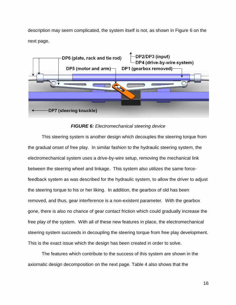
description may seem complicated, the system itself is not, as shown in Figure 6 on the
next page.
FIGURE 6: Electromechanical steering device
This steering system is another design which decouples the steering torque from
the gradual onset of free play. In similar fashion to the hydraulic steering system, the
electromechanical system uses a drive-by-wire setup, removing the mechanical link
between the steering wheel and linkage. This system also utilizes the same force-
feedback system as was described for the hydraulic system, to allow the driver to adjust
the steering torque to his or her liking. In addition, the gearbox of old has been
removed, and thus, gear interference is a non-existent parameter. With the gearbox
gone, there is also no chance of gear contact friction which could gradually increase the
free play of the system. With all of these new features in place, the electromechanical
steering system succeeds in decoupling the steering torque from free play development.
This is the exact issue which the design has been created in order to solve.
The features which contribute to the success of this system are shown in the
axiomatic design decomposition on the next page. Table 4 also shows that the

17
remainder of the steering system still meets the same requirements as those of the
current steering device.
Electromechanical Steering Device
DP
0:
Ele
ctr
om
ech
an
ica
l syste
m
D
P1
: E
limin
ate
gea
rbo
x
D
P2
: A
dju
sta
ble
fo
rce
-fe
edb
ack
D
P3
: In
pu
t d
evic
e
D
P4
: D
rive
-by-w
ire s
yste
m
D
P5
: G
ea
r re
du
ctio
n m
oto
r
D
P6
: P
late
, ra
ck a
nd t
ie r
od
s
D
P7
: S
tee
rin
g k
nu
ckle
s
FR0: Transmit steering input X
FR1: Regulate free play development
X O O O O O O
FR2: Control steering torque
O X O O O O O
FR3: Accept steering input
O O X O O O O
FR4: Transmit input to system
O O O X O O O
FR5: Convert input to linear motion
O O O O X O O
FR6: Transfer work to wheels
O O O O O X O
FR7: Steer front wheels
O O O O O O X
TABLE 4: Decomposition of an electromechanical steering device
As with the hydraulic steering system, there is a variety of equipment on the
modern market which could drive a device such as this one. Almost any motor can be
equipped with the necessary armature, so the only constraint is the torque of the motor.
The distance between the motor shaft and the bearing on the transfer plate varies from
two to four inches, so the maximum required torque is 3500 pounds per inch, which is a
lot. While shopping around, I was able to locate a motor whose gearbox is rated for
2400 pounds per inch of torque. This amount is then augmented by a torque multiplier
value, some of which were in the hundreds (MotorTech 2007). Though I was not able to

18
locate a specific motor for this system, I was able to recognize that there are gear-
motors available which have the necessary torque rating for this device. Also, because
many gear-motors are capable of spinning at a triple-digit number of revolutions per
minute, steering quickness is not an issue. The driver will still be capable of reacting to
danger as quickly as he or she would with a mechanical steering system.
The next step of the project is to analyze certain components of the new steering
systems, to see if they can stand up to the demands of vehicular control.

19
Testing
The steering system designs in this project did not reach the construction stage.
As a result, the analysis involved the use of finite element analysis on some of the key
components. These components included the pinion from design one, the rack bar from
design two, and the rack bar and transfer plate from design three. Appropriate
materials were chosen for each part prior to analysis.
To obtain an applied load value for finite element analysis, I measured the
steering input force for a real automobile. A torque wrench was attached to the steering
column of a Porsche 944, which uses a manual rack and pinion steering system similar
to the one in the introduction. With the car at rest, the shaft was turned through one
complete revolution, and the setting of the wrench was increased each time it clicked.
This occurred up to a torque of twenty-one foot-pounds, after which the wrench did not
click. This gave me an experimental force with which to test my solid models. With this
force value in hand, it was a simple matter of calculating the torque at the pinion. When
I reverse-engineered the physical steering device, I calculated that the inner radius of
the pinion (without the teeth) was 0.213 inches, and the outer radius (with the teeth)
was 0.363 inches. Therefore, the average distance from the center of the pinion to the
face of any tooth is 0.288 inches. By doing a simple torque conversion, twenty-one foot
pounds is the same as 875 pounds at 0.288 inches, or 437.5 pounds at each front
steering knuckle. These are reasonable values, considering that the tires have to be
twisted around while they are being pushed into the pavement by the weight of the car.
In order to interpret the results of finite element analysis, an appropriate lower
limit must be determined for the factor of safety. This number is a ratio of the breaking

20
strength of a material over the applied load. For example, if the load is exactly the
same as the breaking strength, the factor of safety is one. If the load is half of the
breaking strength, the factor of safety is two. Because of the sudden loads and load
reversals taking place in a steering system, the factor of safety should be at least equal
to two. Depending on the value for each of the analyzed components, they may or may
not be considered as candidates for design optimization.
First, I performed finite element analysis on the rack bars from the hydraulic and
electromechanical steering systems. In both of these components, the two mounting
points have to withstand a combined force of 875 pounds. So, 437.5 pounds was
applied laterally to each location, and the components were restrained where the tie
rods are installed at the ends. This configuration is shown in Figure 7 below. Both
components were tested using AISI 1020 steel as the material, and the analyses were
carried out.
FIGURE 7: Rack bar FEA setup
The hydraulic rack bar passed with a minimum factor of safety of 8.26, making it
many times stronger than necessary. The electromechanical rack bar also passed finite
element analysis, with a minimum factor of safety of 3.11. On the basis of these values,

21
both of the components are good candidates for optimization, and that process is
described in the next section.
The electromechanical transfer plate was also tested using finite element
analysis. The load and restraints were positioned as shown below in Figure 8, with the
same color configuration as used in Figure 7.
FIGURE 8: Transfer plate FEA setup
AISI 1020 was used as the material once again, but the result yielded a minimum factor
of safety of just 1.94. This value is a bit lower than two, so a quick adjustment was
made, changing the material to Alloy Steel. This metal is both lighter and stronger than
AISI 1020, so it should benefit the component in both of those ways. The result was a
new minimum factor of safety of 3.42, which is an acceptable result. This component,
like the rack bars, will be optimized in the next section.
Finally, the roller pinion was subjected to finite element analysis. Because of the
diminutive size of this component, Alloy Steel was chosen as a strong starting material.
The load and restraint locations are shown in Figure 9 on the next page, once again
using the same color configuration as Figure 7. Note that the restraints occur on both
ends of the pinion, and not just the end which is visible. They also continue through the
central tunnel inside of the component, because this is the location of the steering shaft
in the full assembly.

22
Figure 9: Roller pinion FEA setup
Unfortunately, the roller pinion did not pass finite element analysis. Even with
Alloy Steel as the material, the minimum factor of safety was just 0.08 which is
unacceptably low. The weak areas of the component are shown below in Figure 10.
FIGURE 10: Roller pinion with FOS < 2 indicated in red

23
As you can see, the downfall of this component is that the spokes, as well as the
end plates, are too thin. In order for this design to cope with 875 pounds of force, it will
have to be optimized. Otherwise, it will break as soon as the driver attempts to steer
the vehicle. This finite element failure is an excellent justification for optimization. The
only difference is that unlike the other three parts, this one will have to be strengthened
rather than weakened.

24
Optimization
For each of the four critical components which were analyzed using finite
element analysis, the minimum factor of safety was determined. For three of these
components, this value came out higher than needed. This result meant that the
components were much stronger than necessary, and could be made lighter and
cheaper without sacrificing their functionality. This is accomplished through a process
called optimization.
The two rack bars had excellent minimum factors of safety. The rack from the
hydraulic steering system had an outstanding minimum value of 8.26, and the one from
the electromechanical steering system had a minimum value of 3.11. The reason why
one of these parts had a higher factor of safety is that the mounting points for the
hydraulic rams are more substantial than the mounting brackets for the transfer plate.
As a result, I decided to optimize both racks in a way that would not affect those areas.
Because these components are almost identical, they can be optimized in many
of the same ways. I decided to hollow out both of them, leaving the outer shells and
mounting points the same. I removed a three-quarter inch diameter cylinder from the
inner center of the hydraulic rack, and a half-inch diameter cylinder from the
electromechanical rack. This brought the hydraulic bar’s factor of safety to 5.92 and the
electromechanical bar’s factor of safety to 2.67. Because the former of these values
was still high, I changed the material to AISI 304, which lowered the minimum factor of
safety to 3.48. This value is much closer to the desired value of two, and therefore
more practical for a steering system setup. In terms of weight savings, both
components started at around 5.7 pounds, and were lightened to 2.8 pounds and 4.4

25
pounds, respectively. Thus, these optimizations had the benefit of reducing both weight
and volume of material in both of their respective steering systems.
The transfer plate from the electromechanical device was also considered for
optimization. With a factor of safety of 3.42, the component is capable of having its
frame reduced without compromising the safety of the component. The extent of the
reduction is shown below in Figure 11.
FIGURE 11: Transfer plate optimization
On the original transfer plate, the perpendicular distance between the cutouts
and the long edges was one half of an inch. On the optimized version of the model this
distance was halved, to one quarter of an inch. The rounding fillets inside the cutouts
are strengthening features of the plate, and thus were kept in the design. The final
minimum factor of safety came out at 2.39, which is far closer to the intended value of
two. Also of note, the starting weight of the plate was 1.8 pounds, and the weight after
optimization was just 1.3 pounds using the same.
The roller pinion was the last component to be scheduled for optimization.
Unfortunately, the 0.08 factor of safety did not bode well for the eventual success of the
device, and those doubts were soon justified. Because of the specific function of the
roller pinion, the only areas that could be modified were the end plates and the central
tube. Even when the thickness of those areas was doubled, the design failed the finite
element analysis once again. With a final factor of safety of just 0.12, this component

26
will require more extensive optimization. The most likely scenario would involve an up-
scaling of the roller pinion, possibly to twice its original size.
To test this theory, I doubled the dimensions of the roller pinion, and performed
the finite element analysis again. Using the same Alloy Steel material, I determined a
new minimum factor of safety of 0.51. This may still be low, but it is a surprising result.
Having increased the dimensions by a factor of two, I managed to increase the factor of
safety by a multiple of four. If this trend holds true, the component will only have to be
doubled in size one more time to meet the design requirements.
In the end, three of my four critical components passed finite element analysis
and were successfully optimized. The fourth component will need more work, but
conceptually speaking, it is a definitely a design idea that is worth pursuing.

27
Discussion
At the beginning of this project, an objective was established. That objective has
clearly been met with the three new steering system designs which I have presented.
All of them still succeed in performing the duty of a current steering device, while also
addressing the fundamental problem of coupling between steering torque and free play
development.
The hydraulic and electromechanical steering systems certainly managed to
decouple these problems, but they also presented another safety-related difficulty. If
there is ever a power failure in the vehicle, the motor and hydraulic pumps will shut
down, resulting in a total loss of steering control. This shortfall requires that some type
of redundant safety mechanism be integrated into the vehicle’s electrical system. Once
that mechanism is in place, the vehicle will operate safely. This consideration is also a
good example of why the current steering system, despite its shortcomings, is the most
reliable of the bunch. If the car quits, the steering continues to work.
The roller pinion steering system, of course, carries on that tradition by using a
mechanical steering shaft. However, it also presents a unique challenge with its tiny
pinion. Because this component did not pass FEA, it needs to be strengthened in order
to work without breaking. This is no simple task, since the minimum factor of safety was
only 0.08 which is more than ten times less than unity. A number of different metals
were tested, but the results stayed the same. In the end, the best and most reliable way
to improve the strength of the roller pinion is to make it bigger. If the entire steering
system is scaled up by a multiplicative factor, the factor of safety will surely increase.
However, this will also increase the torque required to steer the vehicle, which in turn

28
can be remedied by increasing the length of the steering knuckles. This was one of the
situations which I encountered over and over again in the design process - whenever
one problem was solved, another coupled issue presents itself.
This design process was efficient in its use of foundation components. Though
each design had unique features, all of the steering systems were based on the same
basic frame. All of the linkages used the same geometry, and the rack housings were
identical except for the eventual deletion of the gearbox. This consistency shows that
such devices are easily able to be integrated into existing steering systems without
sacrificing extra space. The only exception is the hydraulic system, which will take up
more space because of its remotely-located pumps. They could also be quite heavy,
but that is a problem which will be addressed by someone who undertakes the task of
building such a device.

29
Conclusion
Based on the results of my project, I can claim that it is possible to design
methods for reducing free play in an automotive steering system. These designs are
capable of decoupling the problematic link between steering torque and free play which
exists in current steering systems. The designs can also be made to meet certain
functional and structural requirements, meaning that they have real-world potential
outside of a computer simulation.

30
Bibliography Diekhans, Norbert. Electrohydraulic Steering System. CLAAS KGaA, assignee. Patent
6,067,782. 30 Jan 1998. USPTO. 21 Apr 2009 <http://patft.uspto.gov/netacgi/nph-Parser?Sect1=PTO1&Sect2=HITOFF&d=
PALL&p=1&u=%2Fnetahtml%2FPTO%2Fsrchnum.htm&r=1&f=G&l=50&s1=6067782.PN.&OS=PN/6067782&RS=PN/6067782>
Edson, Joey D, et al. Electrically Acutated, Hydraulic Power Steering System. Fluid
Routing Solutions, Inc, assignee. Patent 7,487,856. 30 Aug 2006. USPTO. 27 Apr 2009 < http://patft.uspto.gov/netacgi/nph-Parser?Sect1=PTO2&Sect2=
HITOFF&p=1&u=%2Fnetahtml%2FPTO%2Fsearch-bool.html&r=5&f=G&l=50 &co1=AND&d=PTXT&s1=%22rack+pinion+steering%22&OS=%22rack+pinion+s
teering%22&RS=%22rack+pinion+steering%22> Esposito, Anthony. Machine Design. Columbus, OH: Charles E. Merrill Publishing
Company, 1975. Limpert, Rudolf. Vehicle System Components: Design and Safety. New York, NY:
John Wiley & Sons, 1982. McMaster-Carr. 2009. McMaster-Carr Supply Company. 27 Apr 2009.
<http://www.mcmaster.com/#62205k756/=1n9x1o> MotorTech. 2007. Motor Technology, Inc. 27 Apr 2009. <http://www.motortech.com/ dcgearmotorHILG2_GI.htm> Nice, Karim. "How Car Steering Works." 31 May 2001. HowStuffWorks.com.
<http://auto.howstuffworks.com/steering.htm> 19 Nov 2008. Nice, Karim. "How Gears Work." 16 Nov 2000. HowStuffWorks.com.
<http://science.howstuffworks.com/gear.htm> 1 Dec 2008.