reducing the energy consumption of zigbee with a...
TRANSCRIPT

Reducing the Energy Consumption of
ZigBee with a Power-saving MAC
Protocol
Pablo Suarez Hernandez
Stockholm, February 2008,Master Thesis
Saab Communication - Swedish Institute of Computer ScienceEscuela Superior de Ingenieros - Universidad de Sevilla


Reducing the Energy Consumption of ZigBee with a Power-savingMAC Protocol
Abstract
The ZigBee standard is a common choice for implementing wireless sensor net-works. For a mesh network topology the protocol lacks of adequate power-savingmechanisms, which limits the lifetime of a battery-powered ZigBee network toa few days. This short lifetime drastically restricts the possible applicationscenarios for ZigBee.
To expand the usefulness of ZigBee an implementation has been developed toreplace the default ZigBee MAC protocol with a power-saving protocol denom-inated X-MAC. The stack has been implemented in Contiki Operating System,which features a novel power profiling mechanism. This implementation hasbeen used to verify the power consumption reduction achieved by the stack,saving up to a 90% of energy, and leading to a ten-fold increase in networklifetime at the price of a slight increase of network latency.
I

II
Reducing the Energy Consumption of ZigBee with a Power-savingMAC Protocol
Acknowledgments
I would like to express my gratitude to my advisors, Carl-Gustav Renmarkerfrom Saab Communication and Adam Dunkels and Thiemo Voigt from SICS,for their constant help and support through the work, and for having providedan excellent work environment and all the resources I required. I also want tothank to Nicolas Tsiftes, Zhitao He, Niclas Finne, Joakim Eriksson and FredrikOsterlind, members of the NES group at SICS, for their assistance and forsharing with me their experience and knowledge. Thanks also to my supervisorin the Universidad de Sevilla, David Munoz de la Pena, for his encouragementand for all these years of advice and friendship.
I would like to mention all the wonderful people and friends with whom I sharedmy Swedish experience and that made it worth to stay so far away from home.Thanks specially to Jesus and Agustı, for the unique group we have formedsince our very first day here, and to the rest of the Kista Team that survivedour Erasmus year: Marıa Elena, Barbara, Claudia, Dani, Luis, and Pancho, andall those that are back home, for their friendship and for everything we haveshared.
Now that I am one step away from closing an important age of my life, I can‘thelp looking back to the years I spent studying in Sevilla. This has been atough road many times, but fortunately I never walked alone. I want to thankto the crew of Minas Friki, my flatmates and associates, for all that I learnedfrom them, for the wonderful years we spent together, and for the proud thatI feel of having been part of that adventure. I would also like to thank all myother awesome friends and mates that I made through the years, specially tothe Dungeoneros squad, who still form part of my life despite the distance.
Perhaps being apart from my loved ones is the biggest sacrifice that I have hadto make in my life. This applies to my friends, but specially to my family, myparents and my sister to whom I dedicate this thesis and whatever comes after.Thank you for your love and your support, and for being so close although sofar away.
III

IV
Reducing the Energy Consumption of ZigBee with a Power-savingMAC ProtocolCONTENTS
Contents
Abstract I
Acknowledgments III
Contents V
List of Figures IX
1 Introduction 1
2 Wireless Sensor Networks 3
2.1 Overview . . . . . . . . . . . . . . . . . . . . . . . . . . . . . . . 3
2.2 Target scenarios . . . . . . . . . . . . . . . . . . . . . . . . . . . 4
2.2.1 Environmental sensing . . . . . . . . . . . . . . . . . . . . 4
2.2.2 Security sensing . . . . . . . . . . . . . . . . . . . . . . . 5
2.2.3 Resource tracking . . . . . . . . . . . . . . . . . . . . . . 6
2.2.4 Other scenarios . . . . . . . . . . . . . . . . . . . . . . . . 7
2.3 Network performance evaluation: Parameters and metrics . . . . 8
2.3.1 Traffic load . . . . . . . . . . . . . . . . . . . . . . . . . . 8
2.3.2 Lifetime . . . . . . . . . . . . . . . . . . . . . . . . . . . . 9
2.3.3 Latency . . . . . . . . . . . . . . . . . . . . . . . . . . . . 9
2.3.4 Coverage . . . . . . . . . . . . . . . . . . . . . . . . . . . 9
2.3.5 Cost . . . . . . . . . . . . . . . . . . . . . . . . . . . . . . 10
2.3.6 Security . . . . . . . . . . . . . . . . . . . . . . . . . . . . 10
V
CONTENTS
3 The ZigBee Stack 11
3.1 Overview . . . . . . . . . . . . . . . . . . . . . . . . . . . . . . . 11
3.2 The Physical Layer (PHY) . . . . . . . . . . . . . . . . . . . . . . 14
3.2.1 Overview . . . . . . . . . . . . . . . . . . . . . . . . . . . 14
3.2.2 Frame format . . . . . . . . . . . . . . . . . . . . . . . . . 15
3.3 The Medium Access Control Layer (MAC) . . . . . . . . . . . . . 16
3.3.1 Overview . . . . . . . . . . . . . . . . . . . . . . . . . . . 16
3.3.2 Operating modes . . . . . . . . . . . . . . . . . . . . . . . 17
3.3.3 The CSMA/CA mechanism . . . . . . . . . . . . . . . . . 18
3.3.4 PAN start, network association and maintenance . . . . . 20
3.3.5 Transmission and reception of information . . . . . . . . . 20
3.4 The Network Layer (NWK) . . . . . . . . . . . . . . . . . . . . . 21
3.4.1 Overview . . . . . . . . . . . . . . . . . . . . . . . . . . . 21
3.4.2 Neighbor table . . . . . . . . . . . . . . . . . . . . . . . . 21
3.4.3 Network creation . . . . . . . . . . . . . . . . . . . . . . . 22
3.4.4 Network association . . . . . . . . . . . . . . . . . . . . . 22
3.4.5 Routing . . . . . . . . . . . . . . . . . . . . . . . . . . . . 23
3.5 The Application Layer (APL) . . . . . . . . . . . . . . . . . . . . 25
3.5.1 Overview . . . . . . . . . . . . . . . . . . . . . . . . . . . 25
3.5.2 Application objects and profiles . . . . . . . . . . . . . . . 26
3.5.3 Discovery and binding . . . . . . . . . . . . . . . . . . . . 26
3.5.4 ZDO . . . . . . . . . . . . . . . . . . . . . . . . . . . . . . 26
3.5.5 APS . . . . . . . . . . . . . . . . . . . . . . . . . . . . . . 27
4 The Contiki OS and the Tmote Sky Platform 29
4.1 Overview . . . . . . . . . . . . . . . . . . . . . . . . . . . . . . . 29
4.2 The Contiki Operating System . . . . . . . . . . . . . . . . . . . 30
4.2.1 General description and characteristics . . . . . . . . . . . 30
4.2.2 System architecture . . . . . . . . . . . . . . . . . . . . . 30
4.2.3 The Contiki kernel . . . . . . . . . . . . . . . . . . . . . . 30
4.2.4 Services . . . . . . . . . . . . . . . . . . . . . . . . . . . . 31
4.2.5 Protothreads . . . . . . . . . . . . . . . . . . . . . . . . . 32
4.2.6 Communication stacks . . . . . . . . . . . . . . . . . . . . 34
4.3 The Tmote Sky Platform . . . . . . . . . . . . . . . . . . . . . . 35
VI
CONTENTS
4.3.1 Microprocessor . . . . . . . . . . . . . . . . . . . . . . . . 36
4.3.2 Radio . . . . . . . . . . . . . . . . . . . . . . . . . . . . . 36
5 Power Saving Mechanisms for WSN 39
5.1 Overview . . . . . . . . . . . . . . . . . . . . . . . . . . . . . . . 39
5.2 Energy Waste . . . . . . . . . . . . . . . . . . . . . . . . . . . . . 40
5.3 MAC Protocols Strategies . . . . . . . . . . . . . . . . . . . . . . 40
5.3.1 Asynchronous protocols . . . . . . . . . . . . . . . . . . . 40
5.3.2 Synchronous protocols . . . . . . . . . . . . . . . . . . . . 41
5.4 Proposed MAC Protocols . . . . . . . . . . . . . . . . . . . . . . 41
5.4.1 S-MAC and T-MAC . . . . . . . . . . . . . . . . . . . . . 41
5.4.2 WiseMAC . . . . . . . . . . . . . . . . . . . . . . . . . . . 42
5.4.3 TRAMA . . . . . . . . . . . . . . . . . . . . . . . . . . . . 43
5.4.4 B-MAC and Z-MAC . . . . . . . . . . . . . . . . . . . . . 43
5.4.5 X-MAC . . . . . . . . . . . . . . . . . . . . . . . . . . . . 44
5.5 Other Approaches . . . . . . . . . . . . . . . . . . . . . . . . . . 46
6 Implementation 47
6.1 Software Architecture Overview . . . . . . . . . . . . . . . . . . . 47
6.2 ZigBee Stack Implementation . . . . . . . . . . . . . . . . . . . . 51
6.2.1 Functionalities Implemented . . . . . . . . . . . . . . . . . 51
6.2.2 Contiki main thread . . . . . . . . . . . . . . . . . . . . . 51
6.2.3 Application layer . . . . . . . . . . . . . . . . . . . . . . . 52
6.2.4 Network layer (NWK) . . . . . . . . . . . . . . . . . . . . 52
6.2.5 Medium access control layer (MAC) . . . . . . . . . . . . 54
6.2.6 Physical layer (PHY) . . . . . . . . . . . . . . . . . . . . 56
6.3 The X-MAC Protocol Implementation . . . . . . . . . . . . . . . 57
7 Evaluation 61
7.1 Technical and Practical Aspects . . . . . . . . . . . . . . . . . . . 62
7.2 Scenario 1: Single-hop Energy Consumption . . . . . . . . . . . . 65
7.3 Scenario 2: Single-hop with Contention . . . . . . . . . . . . . . 71
7.4 Scenario 3: Multi-hop . . . . . . . . . . . . . . . . . . . . . . . . 76
8 Conclusions and Future Work 83
VII

CONTENTS
A Frame Formats 87
A.1 PHY layer . . . . . . . . . . . . . . . . . . . . . . . . . . . . . . . 87
A.1.1 PPDU format . . . . . . . . . . . . . . . . . . . . . . . . . 87
A.2 MAC layer . . . . . . . . . . . . . . . . . . . . . . . . . . . . . . 88
A.2.1 General MAC frame format . . . . . . . . . . . . . . . . . 88
A.2.2 Beacon frame format . . . . . . . . . . . . . . . . . . . . . 89
A.2.3 ACK frame format . . . . . . . . . . . . . . . . . . . . . . 90
A.2.4 MAC command frames . . . . . . . . . . . . . . . . . . . 90
A.3 NWK layer . . . . . . . . . . . . . . . . . . . . . . . . . . . . . . 91
A.3.1 General NWK frame format . . . . . . . . . . . . . . . . . 91
A.3.2 NWK command frames . . . . . . . . . . . . . . . . . . . 92
A.4 APL layer . . . . . . . . . . . . . . . . . . . . . . . . . . . . . . . 92
A.4.1 General APL frame format . . . . . . . . . . . . . . . . . 92
B Implementation Details 95
B.1 Global Variables . . . . . . . . . . . . . . . . . . . . . . . . . . . 95
B.2 Functions Implemented . . . . . . . . . . . . . . . . . . . . . . . 97
Bibliography 99
VIII

Reducing the Energy Consumption of ZigBee with a Power-savingMAC ProtocolLIST OF FIGURES
List of Figures
3.1 ZigBee protocol stack. . . . . . . . . . . . . . . . . . . . . . . . . 12
3.2 Star and peer-to-peer topologies [24]. . . . . . . . . . . . . . . . 13
3.3 Cluster tree topology [24]. . . . . . . . . . . . . . . . . . . . . . . 14
3.4 PPDU frame format [24]. . . . . . . . . . . . . . . . . . . . . . . 16
3.5 Superframe structure in beacon based mode [24]. . . . . . . . . . 17
3.6 The CSMA mechanism [24]. . . . . . . . . . . . . . . . . . . . . . 19
4.1 The Rime stack [17]. . . . . . . . . . . . . . . . . . . . . . . . . . 34
4.2 The Tmote Sky node. . . . . . . . . . . . . . . . . . . . . . . . . 36
5.1 X-MAC transmission and reception mechanisms [10]. . . . . . . . 45
6.1 Proposed software architecture. . . . . . . . . . . . . . . . . . . . 48
6.2 Data transmission procedure [24]. . . . . . . . . . . . . . . . . . . 50
6.3 General MAC frame format [24]. . . . . . . . . . . . . . . . . . . 55
6.4 X-MAC powercycle basic scheme. . . . . . . . . . . . . . . . . . . 59
6.5 X-MAC read function basic scheme. . . . . . . . . . . . . . . . . 60
7.1 Scenario 1 scheme . . . . . . . . . . . . . . . . . . . . . . . . . . 66
7.2 Receive mode power consumption, sender node. . . . . . . . . . . 67
7.3 Receive mode power consumption, sink node. . . . . . . . . . . . 68
7.4 Transmit mode power consumption, send node. . . . . . . . . . . 68
7.5 Round trip time. . . . . . . . . . . . . . . . . . . . . . . . . . . . 69
7.6 Scenario 2 scheme . . . . . . . . . . . . . . . . . . . . . . . . . . 72
7.7 Receive mode power consumption with contention and contentionlevel detected. Sender nodes. . . . . . . . . . . . . . . . . . . . . 73
7.8 Receive mode power consumption with contention. Sink node . . 73
IX
LIST OF FIGURES
7.9 Transmit mode power consumption with contention. . . . . . . . 74
7.10 Round trip time with contention. . . . . . . . . . . . . . . . . . . 74
7.11 Scenario 3 scheme. . . . . . . . . . . . . . . . . . . . . . . . . . . 76
7.12 Receive mode power consumption in multihop scenario. . . . . . 78
7.13 Receive mode power consumption in multihop scenario. Com-parision of X-MAC configurations. . . . . . . . . . . . . . . . . . 78
7.14 Round trip time in multi-hop scenario. . . . . . . . . . . . . . . . 79
A.1 PPDU frame format . . . . . . . . . . . . . . . . . . . . . . . . . 87
A.2 General MAC frame format . . . . . . . . . . . . . . . . . . . . . 88
A.3 Frame control field . . . . . . . . . . . . . . . . . . . . . . . . . . 88
A.4 Beacon frame format . . . . . . . . . . . . . . . . . . . . . . . . . 89
A.5 Format of the GTS information field . . . . . . . . . . . . . . . . 89
A.6 Format of pending address field . . . . . . . . . . . . . . . . . . . 90
A.7 Format of the beacon specification field . . . . . . . . . . . . . . 90
A.8 Format of the ACK frame. . . . . . . . . . . . . . . . . . . . . . . 90
A.9 Mac command frame general format . . . . . . . . . . . . . . . . 91
A.10 Network frame general format . . . . . . . . . . . . . . . . . . . . 91
A.11 Frame control field . . . . . . . . . . . . . . . . . . . . . . . . . . 91
A.12 NWK command frames general format . . . . . . . . . . . . . . . 92
A.13 General APL frame format . . . . . . . . . . . . . . . . . . . . . 93
A.14 Frame control field of the APS general frame . . . . . . . . . . . 93
X

Reducing the Energy Consumption of ZigBee with a Power-savingMAC Protocol1. Introduction
Chapter 1
Introduction
The increasing number of wireless-based applications and technologies is chang-ing the mentality and the rules of most Information Technologies systems. Inthe recent years, developments in the semiconductor industry have enabled theappearance of small, cheap and simple devices, known as sensor nodes. Thesenodes are capable to sense a number of physical magnitudes, to transmit andreceive information to and from other nodes, and to benefit from the low powerconsumption of its components, resulting in an extended power autonomy.
The introduction of this technology in the industry has allowed the developmentof a number of new applications, and the improvement of many existing ones.These applications range from domotics and automation products to civil de-fense systems and military applications. This market has been growing duringthe recent years. Many companies are starting to show interest in new devel-opments and new products based on wireless sensors are being introduced inthe market. Also, research groups around the world are constantly workingand improving the existing technology, and the wireless sensor network (WSN)development community grows every year with students that find this area in-teresting and full of possibilities.
The Networked Embedded Systems Group of the Swedish Institute of ComputerScience (SICS), located in Stockholm, is an acclaimed and remarkable researchgroup in this field. They have developed their own operating system, Contiki,which is now one of the most popular among users and developers of wirelesssensor systems. Contiki was developed for memory-constrained embedded sys-tems, like the wireless sensor nodes. It has a number of advanced features,it is easy to port and has already been implemented in a number of differentplatforms.
One of the main challenges that the development of this kind of network presentsis to decrease the power consumption as much as possible, extending the life-time of the battery powered nodes long enough to be considered a good optionfor scenarios where battery replacement must be done as seldom as possible.Extending the battery life long enough can greatly improve the possible ap-plications and boost the commercial success. It is therefore one of the mainsubjects being researched by WSN developers.
1

There are several approaches to this goal. Many of them focus in medium ac-cess control (MAC) protocols. MAC protocols are used in every shared-mediumnetwork. Their main task is to avoid collisions among nodes trying to ac-cess the channel at the same time. There exist a number of developed MACprotocols that have been in use for a long time, like time multiplexing basedschedules (TDMA) or channel assessments procedures (CSMA), that have beenimplemented in many different kinds of wireless networks. However, the specialrequirements of wireless wensor networks have motivated the development ofmore specific MAC protocols that also deal with energy efficiency as well asother relevant factors like scalability or latency.
SAAB Communication delivers solutions based in WSN in a wide range of prod-ucts, and is interested in further development of this technology, specially in thefield of energy efficiency and robustness. Although no standard exists that fullymeets SAAB’s requirements, the use of existing standards is desirable sincevaluable work has been put into making the design choices defining them.
The ZigBee-IEEE 802.15.4 stack is one of the most popular choices for WSNdevelopment. The set covers network forming, routing and security protocols.Still, further development is required to obtain improved performance in termsof energy consumption in mesh-based networks.
This Master Thesis is the result of a research project carried out for SAAB Com-munication in collaboration with SICS. Hardware and all the required resourceswere provided by both organizations. This work also represents the author’s fi-nal project of its Telecommunication Engineering program at the “Universidadde Sevilla”.
The aim of this work has been to implement a version of the ZigBee stack usingthe Contiki operating system, and to improve it by developing a MAC proto-col in order to save as much energy as possible in different scenarios. Severalexperiments were realized to determine the performance of the designed imple-mentation, and important conclusions and future work ideas were obtained.
The rest of the report is structured as follows: Chapter 2 provides a generalintroduction and description of the most relevant characteristics and considera-tions regarding wireless sensor networks. Chapter 3 provides a description of theZigBee standard, focusing on the different layers of the standard. Chapter 4 pro-vides background information of the Contiki OS and the Tmote Sky platform.Chapter 5 covers different existing alternatives of power saving mechanismsfor wireless sensor networks, describing several MAC protocols already devel-oped. Chapter 6 describes the implementation that was developed to achievethe objectives described above. Chapter 7 provides detailed results of severalexperiments carried out to determine the performance of the designed imple-mentation. Finally, the thesis is concluded in chapter 8 with a summary of themain conclusions and several proposals for possible future work ideas.
2
Reducing the Energy Consumption of ZigBee with a Power-savingMAC Protocol2. Wireless Sensor Networks
Chapter 2
Wireless Sensor Networks
2.1 Overview
New applications based on embedded systems and mobile technologies havecaused a significant growth in wireless communication systems. Those relatedwith Internet, such as web browsing or e-mail, require high data throughputand bandwidth. The Institute of Electrical and Electronic Engineers (IEEE)published the standard 802.11, defining wireless local area networks. This stan-dard is used in the majority of these services. There are a number of versionsof this standard, working in different frequency bands and providing differenttransmission rates and communication ranges. The version 802.11.n is currentlyunder development and it will allow data rates of up to 300Mbit/s [2].
Wireless personal area networks (WPANs)[29] are based strictly in ad-hoc com-munication and do not employ any kind of fixed infrastructure. IEEE stan-dardized the previous development performed by the Bluetooth Special InterestGroup (SIG)[1] creating the 802.15 group[2]. More recently, a special typeof WPANs has been defined, with lower throughput requirements and gener-ally involving sensing mechanisms. These are known as low-rate WPANs (LR-WPANs), or more commonly, wireless sensor networks (WSNs) [22].
A very clarifying initial definition of a WSN is proposed by Hill [23]. Theequation:
Sensing + CPU + Radio = Thousands of potential applications
defines accurately the wide range of different possibilities that the combinationof equipment able to sense different physical magnitudes (temperature, move-ment or light) with tiny, embedded electronic systems and wireless communica-tion capabilities can provide.
A WSN consists of a large number of sensor nodes that employ wireless commu-nication to transmit information between each other. The sensor nodes are tinyembedded devices with low computational and memory capacities that featurea number of sensing devices. Such devices can autonomously form a network
3

2.2. Target scenarios
through which the collected sensor data is transported. A WSN is normallyconsidered a wireless ad-hoc network, featuring self-configuration and quick de-ployment capacities, as well as support for multi-hop routing.
Sensor nodes are typically equipped with a radio transceiver, a low-capacitymicrocontroller, a power source (generally a battery) and sensing equipment fordifferent magnitudes. Their size can vary depending on their complexity andtheir integration level. Previous work [36] have proposed large scale networksusing tiny nodes of microscopic dimensions and very low cost. The present stateof technology however require further development to fulfill the ideal require-ments of this kind of deployment.
There are many potential applications and services employing a wireless sen-sor network [34]. Each of them have their own requirements and constraints,based on the present-day technological status. Factors like price, size or batterylifetime of the nodes must be taken into account in order to develop successfulproducts and services. Given the special characteristics of WSN, and the lackof infrastructure or nodes with higher capacity, one of the main challenges con-sists of adequately designing individual nodes according to the expected systemrequirements. It is therefore important to determine the different target appli-cations, and to identify the special requirements and characteristics in a networklevel, that determine the design of the individual nodes in both hardware andsoftware levels.
Sensor networks have many potential applications and scenarios. They are de-scribed in next section. There are also a number of design parameters andperformance factor, that depend on the chosen application, and that are de-scribed in section 2.3.
2.2 Target scenarios
Previous work [23, 11] agree in defining the following different types of appli-cations as the most relevant and representative scenarios. Combinations of thecharacteristics of each basic application result in a vast number of possibilitiesthat prove the versatility of WSNs and justify the efforts made in the develop-ment of this kind of systems.
2.2.1 Environmental sensing
The low-cost, long battery lifetime and scalability of a WSN can be applied tothose activities based on the measuring of different values in different points ina large area. A scientist can deploy a network of tiny nodes that would providereadings on different physical magnitudes, and transmit the information to asink node after transmitting it through the network. Given that the system canwork for a long time, long-term trends or seasonal changes can be easily loggedand studied.
Another possible scenario might consist in the real-time monitoring of differ-ent magnitudes in the crop fields of a farm, integrating the WSN with other
4
2. Wireless Sensor Networks
kind of automated devices, developing the concept of “Intelligent Agriculture”.If the amount of water required in different areas of crop fields can be accu-rately determined thanks to the monitoring of rainfall in different plots thatcan be thousands of square kilometers large, money and precious resources canbe saved.
It is important to keep in mind that the sensor nodes that form a WSN caninclude a great variety of sensing devices, so a scientist, farmer, or any potentialuser can obtain information about almost any measurable magnitude, includingtemperature, sound, vibration, pressure, motion or pollutants.
In this specific scenario, the network requires to have a high number of nodesscattered in a large area, meaning that multi-hop capabilities are required. Anetwork coordinator, that may have higher computational capacity, is the finaldestination of all messages issued by the sensing nodes. Data rates in this kindof scenario are very low, although this may differ depending on the quality andfrequency of the measures to be taken, as well as the real-time requirements ofthe selected application. Given that it is likely that the nodes would be dis-tributed evenly, the most usual network topology is that of a “mesh network”.It is therefore important to have a good routing strategy to optimize the trans-mission of the messages through the network and to the final destination node.Another option is to implement a tree-based routing network, if the design pa-rameters determine that it is a better solution to have a number of high capacitynodes that may work as a sink for a number of child nodes.
Nodes deployed in the target area send information periodically. Depending onthe requirements of the application the frequency of transmissions may vary, butfor a typical environment monitoring scenario rates are expected to be between1 and 15 minutes between messages [23], since generally, the parameters beingmeasured change slowly enough as to be correctly studied with such frequencyrate.
Battery lifetime is a crucial parameter in this case. Given that most of theenergy consumed by a node is caused by the radio operation, either sending orreceiving packets or simply waiting in listen mode for an incoming transmission[30], sensing nodes must remain in sleep mode most of the time, in order to saveas much energy as possible. Still, most of the nodes are not in range of the finaldestination, so there must be a synchronization procedure that provides reliablecommunication in a multi-hop network while allowing the nodes to spend asmuch time as possible in sleep mode in order to save energy.
The most important performance parameters of this kind of applications are:
• Long lifetime.
• Low data rates—latency is not critical.
• Topologies allowing to cover a vast area (multi-hop capacity).
2.2.2 Security sensing
One of the earliest proposed uses of WSNs was related with military defensivesystems and surveillance applications [11]. The versatile elements that form
5
2.2. Target scenarios
a WSN provide a wide range of solutions in both the fields of military andcivilian defense and security. A WSN is specially suitable to guard defensiveperimeters, alerting when non-authorized access occurs in a secure area, ormonitoring critical parameters in certain locations as temperature or radiationin power plants.
The capacity to detect movement and anomalies can be specially interesting andvaluable in restricted facilities, that require the highest security levels, such asairports, harbors or other military installations. Furthermore, sensor nodes canbe used to identify targets or locate friendly troops in a battlefield, or can alsobe used for tasks as control of civilian activities, tracking different parameterslike movement or implementing elements like acoustic microphones.
A WSN can be integrated in a high scale, integral security system, operatingalong with other kind of sensors and surveillance equipment, like radars or smartcameras. This can become a very powerful tool for both police forces and privatesecurity companies, improving the efficiency of police forces and private guardsand contributing to a safer world.
Taking a closer look at the characteristics of this kind of network, a very impor-tant feature is that, instead of collecting information, the nodes only transmitdata when certain events occur, triggering alarms that should spread throughthe network so that security operators can take appropriate actions.
Reliability is also a key requirement. Every node should send periodically asignal to notify the network that it is working properly. This way, controllers candetect possible security violations in areas where nodes have stopped working,and replace the fallen nodes as soon as possible. Additionally, other robustnessrequirements should be taken into account. For instance solutions may includeimplementing a mesh topology network in order to have redundancy in theavailable routes in an eventual node malfunction or even an electronic attackon the network.
Another important feature of this kind of networks is the requirement to have alow latency value for alarm messages. If a security violation occurs, immediateactions may be required to be taken, and therefore alarm situations should bereported generally within a second. In a large-scale network, this can represent achallenge because every hop supposes an additional delay. Additionally, power-saving schemes must be adapted to provide a reasonable battery lifetime whileensuring the required latency value.
The most important performance parameters of this kind of applications are:
• Robustness and reliability.
• Low latency.
• Low data rates.
2.2.3 Resource tracking
Assets tracking and supply chain management are interesting fields for the im-plementation of WSNs. In large-scale industrial activities, real time information
6
2. Wireless Sensor Networks
on the location of relevant resources or people can improve the performance ofmany operations. Given that one of the most interesting characteristics of sen-sor nodes is its mobility, attaching these nodes to moving components within aproductive process can result in an improvement of productivity (and profit).
Sensor nodes can be tracked while moving through any area within the range ofa sensor network. In this case, moving nodes are attached to valuable resources,while static ones can control flows within the process or provide real-time in-ventory information. Additionally, customers may benefit of the existence of aWSN by tracking products through different stages of a delivery process, if theyare allowed to access the tracking information that the network can provide.
In this kind of scenario, nodes attached to moving objects can actually be consid-ered passive emitters, since all they have to do is send a tracking signal regularlyin intervals that can be considered long enough as to allow a very high powerautonomy. On the other hand, static nodes tracking the location and status ofthe moving ones could be placed in fixed positions and be line-powered.
It is also important that the network is ready to modify its routing schemesince a number of the elements conforming it will be constantly moving. In adeployment involving a high number of elements being tracked, having cheapand simple tracking devices to tag the different elements is a requirement. Costshould be low enough as to consider replacing the nodes that stop working fornew ones.
Unlike in the previous proposed scenarios, mobility in this case is a key factorthat must be considered when designing the network. The system needs to becapable of supporting a network topology that changes in time as the trackingnodes change their location.
The most important performance parameters of this kind of applications are:
• Mobility of devices, re-configuration of network topology on the run.
• Low data rates.
• Low cost.
2.2.4 Other scenarios
The three scenarios described provide a wide idea of the possibilities that a WSNcan achieve. The simplicity of the nodes deployed makes it easy to combinedifferent elements to fulfill other requirements in each specific case. This is whyan important phase in the network design is to determine the exact requirementsthat the system will have, and to express them in the appropriate terms sothat they can be considered as design constraints for the elements forming thenetwork.
7

2.3. Network performance evaluation: Parameters and metrics
2.3 Network performance evaluation: Parame-ters and metrics
The preliminary study of the different target scenarios and applications allowsto extract performance objectives and parameters that determine the suitabilityof a network for different usages.Different networks have different objectives andrequirements. Several authors [23, 11] have proposed a number of metrics thatmust be considered when studying the performance and design of WSN fordifferent target applications:
• Traffic load.
• Lifetime.
• Latency.
• Coverage.
• Cost.
• Security.
Hill [23] states that some of these parameters are interrelated. Power-savingmechanisms involving synchronization or long sleep periods can increase the la-tency. Higher traffic rates will generally involve longer listen periods, decreasingthe battery lifetime.
This set of parameters must be determined carefully, considering both the net-work requirements and the sensor nodes characteristics.
2.3.1 Traffic load
Traffic load is determined by the amount of information that the WSN is re-quired to transmit. In data collecting scenarios the accuracy of the obtainedinformation depends on the number of samples considered. In cases where thenetwork tracks for events such as alarm, the traffic load is likely to be very lowunless many control messages are included in the network to maintain track ofthe different nodes and their status.
The network dependency on the traffic load is evident. Energy consumptiongenerally depends on the number of packets transmitted, since most transmis-sion schemes vary their parameters to be able to carry the amount of expectedtraffic while consuming the less possible energy by turning the radio off period-ically. An excess of traffic in the network can also have an impact in latency ifthe network is not capable of handling all the frames, resulting in higher delays.
Another aspect that must be considered is that in some cases it is required thatthe network is designed to handle a sudden change of traffic rate caused by anexternal event (like an alarm) that require a higher transmission throughput inorder to fulfill the application requirements.
8

2. Wireless Sensor Networks
2.3.2 Lifetime
In most scenarios a very interesting option of a WSN consists of being ableto place a number of nodes in a vast operational area, whether a field beingstudied in a environmental monitoring application or a security perimeter ora critical location in security sensing applications. Many times, this involveshaving unattended nodes for as long time as possible. This is limited by thebattery life of the device, so each node should perform its tasks while trying tominimize its power consumption as much as possible.
Given that a node performs different operations, it is important to have anaccurate knowledge on how the energy is spent in order to address the problem.Raghnathan et al [30] have proved that most of energy consumption in a sensornode is related with the radio operation. Furthermore, for most low-powerconsumption microcontrollers their consumption compared to the radio devicecan be neglected.
In order to extend the battery lifetime transmissions and receptions must bescheduled so that the radio can be turned off during long periods. This has animpact on other system metrics, mainly latency. This problem is one of the keypoints of this thesis, and is addressed in further sections.
2.3.3 Latency
Latency is a critical parameter in security and surveillance applications in whichintrusions or anomalies must be notified immediately to the authorized person-nel. One consequence of the high consumption of the radio devices is that theminimization of the energy spent in listen mode affects the latency. Communi-cation protocols trying to save power by periodically turning the radio off cannotguarantee an immediate reception of incoming packets, resulting in higher delaysfor the information.
The trade-off between power consumption and response time is extensively stud-ied in chapter 5 of this report, and is one of the most relevant results of theexperiments performed.
2.3.4 Coverage
Coverage is one of the most important parameters related with the specific sce-nario that a WSN is designed for. Depending on the requirements, the numberand the transmission power of the nodes is affected, resulting in the desiredphysical range of the network. If multi-hop communications are introduced inorder to extend the network coverage, latency is also increased because of thenecessity to perform more than one transmission to reach a final destination.
Scalability is also related with coverage, since a user might be interested inincreasing the network range by adding more nodes to a deployed system. Thenetwork must be capable of scaling itself in order to adapt to the requirementsof each specific situation.
9

2.3. Network performance evaluation: Parameters and metrics
2.3.5 Cost
Given the logical relation between the overall system capacity and the cost, it isimportant to properly calibrate the system performance requirements in orderto minimize the budget of the product. An extensive knowledge of both theavailable equipment and the application requirements can provide affordablesolutions in each case.
Other parameters of the network may have an impact on the economic cost, butit is a fact that most of available equipment in the WSN field is versatile enoughas to work in different configurations and with different requirements. Anotheraspect that must also be considered when determining the cost of a system isthe capacity of self reparation and self awareness of the status of the network.
Maintenance and reparation of the network also determine the economic ex-penses for a WSN deployment. Minimizing them is possible if the designednetwork is capable of auto configuring itself for any topology or application, aswell as providing accurate information on failing elements and indicating solu-tions to the user. A WSN must be considered as a tool that non-technicallyskilled users can employ. Having a user-friendly interface and the autonomyexposed above increases the final value of the product.
2.3.6 Security
Once again, security requirements and its impact on the other network parame-ters depend on the application implemented. Obviously, those scenarios relatedto defensive or security system have higher requirements in this field.
The security requirements must be addressed from different points of view.Information encryption and authentication are measures to be considered toprotect the data transmitted. The result of using these techniques is a higheramount of traffic in the network, which can affect the system overall performancesince more redundancy traffic is inserted in the system.
Robust systems must also be designed to face unexpected events or even elec-tronic attacks from hostile parties. Increasing the number of nodes in a mesh-network topology provides a route redundancy that can be helpful to deal withthese situations, with a higher economic cost. Other solutions include usingmulti-channel devices.
Summarizing, a number of different applications have been presented. Theseapplications motivate the development of special protocols and standards ca-pable of meeting the requirements in each case, given a number of parametersthat determine the validity and the performance of a wireless sensor network.
10
Reducing the Energy Consumption of ZigBee with a Power-savingMAC Protocol3. The ZigBee Stack
Chapter 3
The ZigBee Stack
Many wireless monitoring and control applications require low data rates andlong battery lifetime. Standards for general-purpose networking like the IEEE802.11 do not fulfill these requirements, since they are designed for infrastructurebased networks that prioritize higher transmission speeds employing devices thatare normally line-powered.
To fulfill the WSN general requirements, a number of standards and protocolshave been developed in order to obtain a feasible solution that enables the useof tiny sensor nodes for all the possible potential applications described before.
For this special kind of wireless systems, the IEEE has developed the 802.15.4specification [24] which is widely used in most WSN-based applications. TheIEEE specification describes the physical and the medium access control layersof the protocol stack.
Different options have been developed for the network and application layersthat can be combined with the 802.15.4 standard to provide different function-alities depending on the target applications. One of such options is ZigBee[7], developed by the ZigBee Alliance [3], an association of companies workingtogether to develop and improve this protocol stack.
This chapter provides a deep study of the 802.15.4-ZigBee stack, covering themain features and providing detailed descriptions of the different layers thatdefine the functionality of the standard.
3.1 Overview
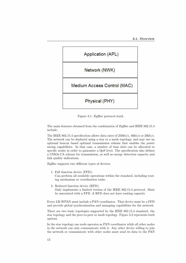
To start with, it is important to understand the difference between the IEEE802.15.4 and the ZigBee standards. ZigBee only specifies the NWK and APLlayers of the stack, and it is built upon the 802.15.4 standard that provide bothPHY and MAC services and functionalities. However, the name of ZigBee isusually applied to the whole stack. Figure 3.1 presents the proposed protocolarchitecture.
11
3.1. Overview
Figure 3.1: ZigBee protocol stack.
The main features obtained from the combination of ZigBee and IEEE 802.15.4include:
The IEEE 802.15.4 specification allows data rates of 250kb/s, 40kb/s or 20kb/s.The network can be deployed using a star or a mesh topology, and may use anoptional beacon based optional transmission scheme that enables the powersaving capabilities. In that case, a number of time slots can be allocated tospecific nodes in order to guarantee a QoS level. The specification also definesa CSMA-CA scheme for transmission, as well as energy detection capacity andlink quality indications.
ZigBee supports two different types of devices:
1. Full function device (FFD):Can perform all available operations within the standard, including rout-ing mechanism or coordination tasks.
2. Reduced function device (RFD):Only implements a limited version of the IEEE 802.15.4 protocol. Mustbe associated with a FFD. A RFD does not have routing capacity
Every LR-WPAN must include a PAN coordinator. That device must be a FFDand provide global synchronization and managing capabilities for the network.
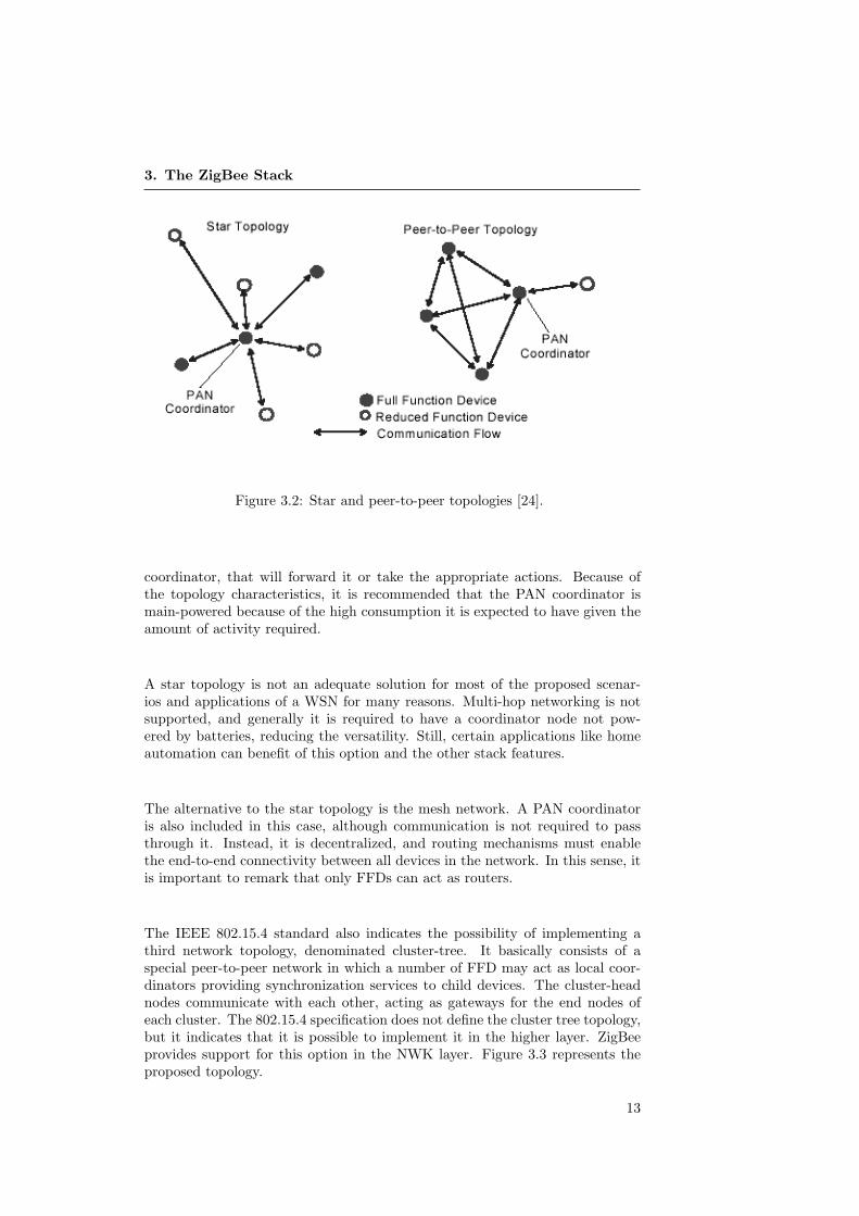
There are two basic topologies supported by the IEEE 802.15.4 standard: thestar topology and the peer-to-peer or mesh topology. Figure 3.2 represents bothoptions.
In the star topology one node operates as PAN coordinator while all other nodesin the network can only communicate with it. Any other device willing to jointhe network or communicate with other nodes must send its data to the PAN
12
3. The ZigBee Stack
Figure 3.2: Star and peer-to-peer topologies [24].
coordinator, that will forward it or take the appropriate actions. Because ofthe topology characteristics, it is recommended that the PAN coordinator ismain-powered because of the high consumption it is expected to have given theamount of activity required.
A star topology is not an adequate solution for most of the proposed scenar-ios and applications of a WSN for many reasons. Multi-hop networking is notsupported, and generally it is required to have a coordinator node not pow-ered by batteries, reducing the versatility. Still, certain applications like homeautomation can benefit of this option and the other stack features.
The alternative to the star topology is the mesh network. A PAN coordinatoris also included in this case, although communication is not required to passthrough it. Instead, it is decentralized, and routing mechanisms must enablethe end-to-end connectivity between all devices in the network. In this sense, itis important to remark that only FFDs can act as routers.
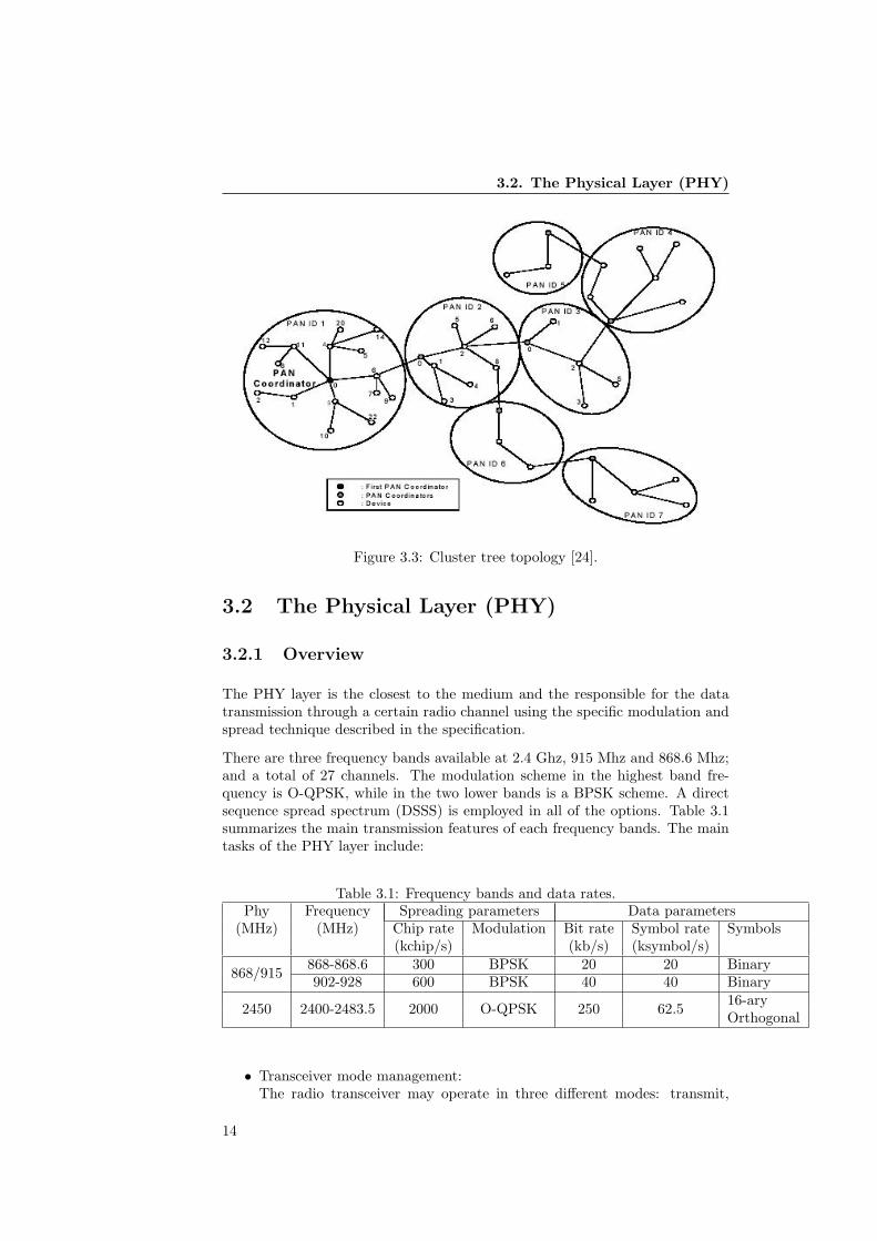
The IEEE 802.15.4 standard also indicates the possibility of implementing athird network topology, denominated cluster-tree. It basically consists of aspecial peer-to-peer network in which a number of FFD may act as local coor-dinators providing synchronization services to child devices. The cluster-headnodes communicate with each other, acting as gateways for the end nodes ofeach cluster. The 802.15.4 specification does not define the cluster tree topology,but it indicates that it is possible to implement it in the higher layer. ZigBeeprovides support for this option in the NWK layer. Figure 3.3 represents theproposed topology.
13
3.2. The Physical Layer (PHY)
Figure 3.3: Cluster tree topology [24].
3.2 The Physical Layer (PHY)
3.2.1 Overview
The PHY layer is the closest to the medium and the responsible for the datatransmission through a certain radio channel using the specific modulation andspread technique described in the specification.
There are three frequency bands available at 2.4 Ghz, 915 Mhz and 868.6 Mhz;and a total of 27 channels. The modulation scheme in the highest band fre-quency is O-QPSK, while in the two lower bands is a BPSK scheme. A directsequence spread spectrum (DSSS) is employed in all of the options. Table 3.1summarizes the main transmission features of each frequency bands. The maintasks of the PHY layer include:
Table 3.1: Frequency bands and data rates.Phy Frequency Spreading parameters Data parameters
(MHz) (MHz) Chip rate Modulation Bit rate Symbol rate Symbols(kchip/s) (kb/s) (ksymbol/s)
868/915 868-868.6 300 BPSK 20 20 Binary902-928 600 BPSK 40 40 Binary
2450 2400-2483.5 2000 O-QPSK 250 62.5 16-aryOrthogonal
• Transceiver mode management:The radio transceiver may operate in three different modes: transmit,
14
3. The ZigBee Stack
receive (or listen) and sleep. The PHY layer turns the device to theappropriate mode upon request of the MAC sub-layer.
• Energy detection (ED):The PHY layer can use the transceiver to perform an estimation of thepower signal present in a specific channel of the supported band. Thisdata can be used by the system, typically to perform a channel assessmentoperation.
• Link quality indication (LQI):A measurement can be performed in incoming packets to determine thestrength/quality relation of a radio link. This information is availablefor the upper layers that can use it with several network maintenanceoperations.
• Clear channel assessment (CCA):Using the ED capability previously described the PHY layer can determineif a channel is idle before starting a transmission.
• Channel frequency selection:The PHY layer is able to tune the transceiver to the appropriate physicalchannel indicated by the MAC layer.
To perform these tasks, the PHY layer features two different services that pro-vide an interface between the MAC layer and the physical radio channel. Theseare the physical data service (PD-DATA) and the physical layer managemententity (PLME). The PD-DATA entity supports the transport of frames betweenpeer MAC layer entities, while the PLME provides a management service inter-face that allow management functions to be invoked. The PLME also maintainsa database of managed parameters belonging to the PHY layer. This is denom-inated PHY PAN information base (PIB). The PIB contains attributes thatdefine different aspects related with the interaction of the device with the phys-ical medium, such as the output power or the current channel in use. Theseattributes can be modified using the management entity of the PHY layer.
3.2.2 Frame format
The PHY layer frames receive the denomination of PPDU (physical protocoldata unit). Its format is shown in Figure 3.4.
A PPDU consists of a synchronization header, which allows receiving devices tosynchronize to the bit stream; a PHY header, containing the frame length value;and the MAC layer payload. Outgoing frames are generated in the PHY layerby adding the header fields to the MAC payload provided by the MAC layer.In the case of incoming frames, the PHY layer extracts its header informationbefore notifying the MAC data entity the reception of the frame.
15

3.3. The Medium Access Control Layer (MAC)
Figure 3.4: PPDU frame format [24].
3.3 The Medium Access Control Layer (MAC)
3.3.1 Overview
The MAC layer of the IEEE 802.15.4 protocol provides an interface between thePHY layer an the higher layers of the stack. The MAC layer handles access tothe physical radio channel and is responsible for the following tasks:
• Generation of beacon frames, if the device is a coordinator and the networkis configured to work in a beacon based mode.
• Synchronization to network beacons.
• PAN association and disassociation support.
• Device security.
• Management of the CSMA-CA mechanism for channel access.
• Management of the GTS mechanism for allocated time slots.
• Provide a reliable link between peer MAC entities.
The MAC layer provides an interface between the next higher layer in the stack(in this case the ZigBee NWK layer) and the PHY layer. As in the PHY layer,two services are defined that provide the required functionalities: The MACdata service, denominated Mac Common Part Sublayer (MCPS) and the MACmanagement service, denominated Mac Layer Management Entity (MLME).These services provide the required interface between the NWK and the PHYlayers, using the PD-DATA and PLME entities and the corresponding ones inthe NWK layer. There is also an implicit interface that allows the MLME to usethe MCPS data service in order to transmit several types of command frames.
The MAC layer maintains a database including information of different param-eters related with the configuration and the operating modes of the device,denominated MAC PIB. These attributes are required to manage the MAClayer, and are accessed and modified by the MLME entity.
One of the most important tasks of the MAC layer is to provide a reliable andcollision free access to the channel. The IEEE 802.15.4 specification definestwo possible options that determine the operating mode of the whole network,depending on the use or not of a beacon enabled mode.
16

3. The ZigBee Stack
3.3.2 Operating modes
Beacon enabled mode
When the beacon enabled mode is active, a superframe structure is used toschedule communication between devices. The PAN coordinator defines theformat of the superframe and notifies it to the other nodes including the infor-mation in periodic beacon frames.
The superframe consists of 16 equally sized slots followed by an inactive periodpreviously defined. A frame can be divided in 3 different parts: ContentionAccess Period (CAP), Contention Free Period (CFP) and an Inactive Period(IP). Figure 3.5 depicts this superframe structure.
Figure 3.5: Superframe structure in beacon based mode [24].
During the CAP, any device willing to communicate must compete for the chan-nel using a slotted CSMA/CA mechanism. In this case the backoff time of thecontention mechanism is aligned with the superframe slot boundaries, so a nodethat is unable to transmit during a time slot of the superframe because ofchannel contention is not allowed to try again until next slot. The CSMA/CAprocedure is described in a later subsection.
The coordinator can also configure the superframe structure to include a con-tention free period. This option allows to meet QoS requirements by allocatinga number of guaranteed time slots (GTSs) to applications that require specificlow latency or throughput values. All contention-based communications musthave been completed before the start of the CFP. Such periods can last longerthan one superframe slot, and are allocated to devices that are allowed transmitwithout collision problems during their GTS.
GTS management is performed by the PAN coordinator. It maintains infor-mation about the number of GTS periods allocated, their length and positionwithin the superframe, as well as information concerning which node can useeach slot. A device willing to be assigned a CFP slot must request it to thecoordinator using a command frame that shall include the main parameters toreconfigure the superframe. Upon reception of the request message, the PANcoordinator sends an acknowledgment frame and determines if the requestedreserved slots can be allocated in the superframe structure.
When the allocation is confirmed, devices are notified using information fieldsincluded in the beacon frames, with all the required parameters that allow the
17
3.3. The Medium Access Control Layer (MAC)
non-coordinator devices to know the format of the upcoming superframe periodas well as details on their GTS allocation.
The coordinator can also decide to define some of the superframe slots as inac-tive. No transmissions are performed in such periods, and devices may enter insleep mode until next beacon frame is received. This way power consumptioncan be decreased in scenarios with low traffic rates, being possible to increasethe CAP or the CFP if the coordinator detects higher amounts of packets.
The beacon-based operating mode is not compatible with a mesh topology,which clearly reduces the ZigBee capabilities in this kind of systems.
Non-beacon enabled mode
When the network is configured by the PAN Coordinator to work in a nonbeacon-enabled mode, the superframe structure and beacon frames are notpresent in the system. In this case, access to the medium is controlled by theunslotted CSMA/CA mechanism. No power-consumption reduction options areavailable in this case. The upper layers can arbitrarily order to turn the radio offduring some periods, but a MAC protocol is required to achieve an acceptableperformance while reducing energy consumption and avoiding collisions in themedium.
Given that this is the only available option for mesh-based topologies, the devel-oping of such MAC protocols and introducing them in the stack is an importantissue that this thesis focuses on, as will be described in later sections.
3.3.3 The CSMA/CA mechanism
The MAC layer uses the CSMA/CA procedure to determine if the channel isidle for the device to start a transmission. This procedure is based on backoffperiods, and must be performed before beginning to transmit. If the channelis detected to be idle, the transmission can be carried out immediately after.Figure 3.6 in next page describes the CSMA/CA mechanism.
There are two different versions of this procedure, depending if the network isoperating in a beacon-enabled scheme or not. The difference lies in the bound-aries of the backoff periods, since in the slotted version they must be alignedwith the superframe slot boundaries, while in the unslotted case the backoffperiods of each device are independent.
Three variables are required to schedule the access to the medium:
• The number of times that the CSMA/CA algorithm is required to backoffwhile attempting to access the current channel (NB in Figure 3.6).
• The contention window length, which defines the number of backoff peri-ods that the channel must be sensed as idle before starting a transmission,and that is only used in the slotted version (CW in figure 3.6).
• The backoff exponent, defining the number of backoff periods that thedevice must wait between assessments attempts (BE in Figure 3.6).
18

3. The ZigBee Stack
Figure 3.6: The CSMA mechanism [24].
19

3.3. The Medium Access Control Layer (MAC)
Additionally, a maximum number of clear channel assessments attempts is de-fined and stored in an internal variable.
3.3.4 PAN start, network association and maintenance
The MAC layer is also responsible of a number of tasks related with the creationand maintenance of a PAN. A FFD can create a PAN after performing a channelscan to determine a suitable channel to use in the newly created network.
After a command from the NWK layer is received, the process begins when thedevice restarts its parameters to the initial configuration. Afterward, a channelscan is performed, and when a suitable option is found the PHY layer tunes thetransceiver to the appropriate frequency and PAN identifier is chosen. The nexthigher layer is notified of these values, and subsequently starts its operation ascoordinator by sending a beacon frame, if this operation mode is selected. Thiswill make neighbor devices aware of the existence of the new network, and theymay join it upon request.
If a device tries to associate to an existing network a scan provides the joiningdevice information on active networks operating within range. The next higherlayer is notified of the network chosen and its parameters, and the MLME issuesa command frame requesting the association to the coordinator of the chosennetwork. When it is received, an acknowledgment frame is automatically gen-erated and transmitted, and the coordinator decides whether the operation canbe completed or not. If there are enough resources available, the coordinatorindicates the joining device its new network address using an association re-sponse command. This special frame is also generated indicating a failure inthe process if the PAN coordinator does not have available resources to allow anew device joining the network.
3.3.5 Transmission and reception of information
The transmission of data packets depends of the configuration of the network,specifically if the beacon enabled mode is in use. If the beacon scheme is enabled,a transmitting device must wait for the next slot in the superframe structureand compete for the channel with other surrounding nodes, or use its GTS slot ifallocated as described before. If the beacon mode is not enabled, the unslottedCSMA/CA mechanism is performed before transmitting data.
Reception of incoming packets can only be accomplished if the transceiver isactive and in receive mode when the incoming frame is detected in the channel.A device receives every transmission complying the standard specification thatis performed in the tuned channel. There is no way to filter frames that are notdestined to the node unless they do not comply the PHY layer conditions toreceive a frame (FCS code check) before they are processed in the MAC layer.Therefore, only those frames with the appropriate PAN identifiers and destina-tion address fields are either notified to the next higher layer or considered formanaging actions in the MAC layer. All other received frames are discarded.
20
3. The ZigBee Stack
3.4 The Network Layer (NWK)
3.4.1 Overview
The network layer provides functionalities to the MAC layer and an interface tothe Application layer. All ZigBee devices must be capable of both joining andleaving a network. Additionally, FFDs must provide the following functionalitiesimplemented in the NWK layer:
• Start a new network, acting as coordinators and allow new devices join it.
• Configuration of joining devices, address assignment.
• Maintain information about neighbor nodes within transmission range.
• Provide routing capacity enabling multi-hop networks.
• Route discovery, route maintenance and route repair.
• Unicast, multicast and broadcast communication.
• Reliable link between peer NWK entities.
The NWK layer provides two services in a similar fashion as the previouslydescribed layers. These are the NWK data service, or NLDE, and the NWKmanagement service or NLME. The interface between the application and theMAC layer is performed via the MCPS and the MLME described before. TheNLDE and the NLME also include an interface that allow them to interact ifthe task requires so.
The NLME also maintains a database of attributes required to manage theNWK layer of a device denominated Network IB. The attributes are accessedor modified using NLME primitives, and include information about the networkparameters and status, as well as specifying some device capacities related withthe networking operations.
3.4.2 Neighbor table
The neighbor table of a device contains information of every device within trans-mission range. It is updated every time a device receives any frame from thecorresponding network. An entry exist for each neighboring device, with thefollowing fields:
• The extended and network addresses of the neighboring device.
• The device type, and the relationship between the neighbor and the cur-rent device..
• The link quality indicator.
• Beacon tracking information.
21

3.4. The Network Layer (NWK)
3.4.3 Network creation
Only a ZigBee FFD with coordinator capabilities can start a new network.This process requires functionalities at different layers, and has partly beendescribed in the MAC layer subsection. Upon request of the next higher layer,the NLME entity commands the start of the procedure by ordering the MAClayer to perform a channel scan.
When results of a successful energy scan are received, the NLME determinesthe ones that are suitable to support the new network, favoring the channelswith no networks or the ones with a lower number of detected networks. Whena channel has been chosen, a PAN Id value is determined and the MAC layer isnotified of the new network configuration. When a confirmation notification isreceived from the MAC layer, the next higher layer is notified of the status ofthe network creation process.
Subsequently, the coordinator must notify the MAC layer that new devices areallowed to join the network, so that the coordinator accepts incoming frames ofdevices willing to join.
3.4.4 Network association
This procedure was partly described in the MAC subsection, since part of thefunctionality is implemented by the lower levels. The procedure for joining a net-work begins upon request of the next higher layer. The NWK layer requests theMAC layer to perform a channel scan in order to discover operating networkswithin communication range. Once the MAC layer signals the completion ofthe scan, the NWK has information on the parameters of the surrounding avail-able networks and the neighboring devices belonging to them. Subsequently,the NWK layer choses one of such networks, and issues a request frame to itscoordinator device.
The procedure continues as described in the MAC layer description, by issuingassociation request command frames. If the attempt is successful, the 16-bitlogical address assigned to the node in the network is received, and is used inany further transmission. Additionally, parameters in the NIB are updated.
If the joining attempt is unsuccessful, the next higher layer is notified anddepending on the reasons of the failure different actions are taken. For instance,if there are other possible available parents in the neighbor table the device mayattempt to join the network by associating with them.
The coordinator device procedure logically represents the other end of the op-erations described above. When the join requests reach the NWK layer of apotential coordinator, they check if there are enough resources to be allocatedfor the new child, like available positions in the neighbor table, available net-work short addresses, etc. If the request is granted, the NLME of the parentdevice create a new entry for the new child in its neighbor table with the sup-plied information, and indicate the successful association with the appropriateresponse frame as described in the MAC subsection.
22
3. The ZigBee Stack
A shorter procedure is also available for devices willing to re-join the networkafter having lost connection with it. Furthermore, it is also possible for a parentdevice to directly associate a device if the 64-bit address of the child is provided.
3.4.5 Routing
ZigBee coordinators and routers must provide the following functionality:
• Relay data frames on behalf of higher layers or other ZigBee routers tothe appropriate destination.
• Participate in route discovery for subsequent data transmissions, as wellas in route repair or maintenance.
• Maintain routing tables to store information about available routes.
The NWK layer maintains a routing table that stores information about differentparameters of already discovered routes. This table is used to determine whatis the next-hop in the path of a multi-hop communication. This table containsthe following fields:
• Destination address (2 bytes): The 16-bit address of the destination de-vice.
• Status (3 bits): Indicate if the route is active, being discovered or inactive.
• Control flags (3 bits): Indicate if the route is many-to-one, if a route recordis required or if the address represents a group address.
• Next hop address: The 16-bit address of the next hop on the way to thedestination.
Additionally, a route discovery table is maintained, which holds different pa-rameters employed in the route discovery procedure. The route discovery tableinclude the following information:
• Route Request ID (1 byte): Sequence number for a route request commandthat identifies a route request.
• Source Address (2 bytes): The 16-bit address of the route request’s initia-tor.
• Sender Address (2 bytes): The 16-bit address of the device that sent themost recent route discovery request to the present device correspondingto this entry identifier and Source Address. This field is used as next-hopfor subsequent reply command frames.
• Expiration time (2 bytes): Countdown timer indicating the number ofmilliseconds until the discovery operation expires.
23
3.4. The Network Layer (NWK)
Routing mechanism
When a data frame is received in the NWK layer, either from the next higherlayer or from the MAC layer, a procedure to successfully deliver the frame to itsfinal destination is started. The device shall check its routing table for an entrycorresponding to the final destination of the frame. If such entry exists, and ifthe route is marked as active in the status field, the frame is forwarded usingthe MAC data entity (MCPS) using the Next-hop field of the correspondingfield of the routing table as MAC destination address.
If the device has a routing table entry corresponding to the routing destinationof the frame, but the status field indicates that the route is being discovered, thedata frame can be buffered pending for the completion of the route discoveryprocess.
Other options include using tree routing in those topologies and network con-figurations that allow it, or generating a source-routed frame, which includesthe addresses of all the different hops until the end node, determined before thetransmission by the original sender device.
If a device has no routing capacity, or if no routing table entry corresponds tothe routing destination of the frame, it is discarded, and the NLDE issues aerror notification to the next higher layer.
Route discovery
The route discovery process is a key element of any network protocol. In ZigBee,a network discovery can be unicast, multicast or many-to-one, depending onthe number of devices discovering and being discovered. Basically, the device ordevices try to establish a route until a destination address, that can be eitherthe regular short address of a single node, a broadcast address or a multicastgroup ID.
The route discovery process is initiated by a ZigBee router or coordinator NWKlayer by request of the next higher layer by specifically issuing a discovery requestcommand. Alternatively, the process can be also started if a frame is generatedin the NWK layer or received by the MAC layer with a field indicating that aroute should be discovered if the final destination address of the frame is notamong the entries of the routing table.
If the device has available space in its routing table, a new entry is createdwith the address to be discovered as destination address, and the status fieldindicating that discovery is underway. Additionally, a route discovery tableentry is created that maintains temporary information about the procedure.Afterward, a route request command frame is generated indicating the finaladdress of the discovery procedure and dispatched using the previously describedMAC mechanism. This frame is broadcasted to all nodes within transmissionrange.
When other devices receive the route request command frame, they check if theaddress being discovered matches their own. If not, they can check if the addressis already in their routing table. If so, the discovery frame is forwarded to the
24
3. The ZigBee Stack
next hop address, and otherwise, it is broadcasted. The intermediate node mayattempt to start its own discovery process using the same forwarded frame. Thisprocedure is performed until either the route is successfully discovered or untilthe route discovery tables timeouts counters expire, signaling a failure in thediscovery attempt in the originator device.
If the device address matches the one included in the discovery frame, a responseis created and sent back to the previous node in the path. The response framefollows the same route that the discovery frame followed, but in the reverse way.Upon reception to an intermediate device, the next hop in the way back to theoriginator is available in the route discovery table. Intermediate devices thatattempted to discover the same route update their routing tables as well.
3.5 The Application Layer (APL)
3.5.1 Overview
The layer in the top of the stack described by the ZigBee specification is the Ap-plication Layer (APL). It consists of several sublayers: the Application Support(APS) sublayer, the ZigBee Device Object (ZDO) and the manufacturer-definedapplication objects.
The APS is responsible for:
• Maintaining tables for binding, or matching two devices together basedon their services.
• Forwarding messages between bound devices.
• Address mapping from 64 bit long address mode to 16 bit NWK shortaddresses.
• Fragmentation and reassembly of data transport.
The APS performs its tasks using two different entities similarly to the lowerlayers. The Application Support Sub-Layer Data Entity (ASPDE) provide thedata service to the Network layer and both the ZDO and the application objects.The Application Support Sub-Layer Management Entity (ASLME) provide amanagement interface to allow the application to interact with the stack. TheZDO is responsible for:
• Defining the role of the device within the network (FFD, RFD or PANCoordinator).
• Discovering devices on the network and determining the application ser-vices they may provide.
• Initiating and responding to binding requests.
• Establishing a secure link between network devices.
This thesis does not focus in application development or interaction, so this onlya brief introduction to the main concepts of the application layer are described.
25
3.5. The Application Layer (APL)
3.5.2 Application objects and profiles
Application objects are hosted in ZigBee devices. Data between them is trans-mitted using the APSDE. The application objects have an overall control of thewhole ZigBee stack functionalities, issuing commands and receiving informationas was described in the different lower layers descriptions. ZigBee supports upto 240 application objects, each interfacing on an indexed endpoint.
At this point, it is important to consider a node as a platform with severaldevices and components, with one radio chip among them. Different elementscan define their own application objects, and normally they require their ownlogical communication channel. Individual parts of the nodes are subunits,containing one device description in each subunit.
The new level of sub-addressing allow different components to work individually.Each application object also includes information about data attributes theycontain.
Application profiles are agreement for messages, message formats and processingactions that allow applications to create a distributed application between localinstallations in different devices. These profiles are a mean to unify differenttechnical solutions with the ZigBee standard.
3.5.3 Discovery and binding
Following a similar procedure as with the NWK case, ZigBee devices can dis-cover each other by issuing query messages that are broadcasted by the lowerlayers. The discovery can consist of either finding out the long or short addressof a specific device. Furthermore, apart from discovering the surrounding de-vices, applications must also obtain information on what kind of services thesenodes can provide. Service discovery can be accomplished by issuing a queryfor each endpoint on a previously discovered device.
Once a device has been discovered, ZigBee allows to create logical links betweencomplementary application devices and endpoints. This concept is denominatedBinding. A binding table is implemented with information about this logicallink. Binding is always performed after the establishment of a communicationlink.
3.5.4 ZDO
According to the specification, ZigBee Device Objects is an application whichemploys resources belonging to the APS and the lower layers to implementfunctionalities of ZigBee End Devices, ZigBee Routers or ZigBee Coordinators.
The ZigBee Device Objects reside in the APL above the APS sublayer. They areresponsible for initializing all the stack components according to the specifiednode type, as well as assembling configuration information from end applicationsand to manage the network, security issues, etc.
26
3. The ZigBee Stack
3.5.5 APS
The APS sublayer provides an interface between the NWK and APL layersthrough a set of services that can be used by the ZDO and the manufacturer-defined application objects. It consists of a data entity (APSDE) and a man-agement entity (APSME), similarly to the other layers previously described.
The APSDE provides a data service to the network layer and both the ZDOand application objects, allowing the transport of application data units betweentwo or more devices. The APSME provides a management service that allowsan application to interact with the rest of the stack. Among other functions,this entity is in charge of matching devices together based on their services andneeds (binding), as well as security tasks.
27

3.5. The Application Layer (APL)
28

Reducing the Energy Consumption of ZigBee with a Power-savingMAC Protocol4. The Contiki OS and the Tmote Sky Platform
Chapter 4
The Contiki OS and theTmote Sky Platform
4.1 Overview
Sensor nodes are generally constrained in memory and computational capacity.The small physical size and the low cost intended for the devices impose alimit that must be taken into account when designing an application. Typicalplatforms are equipped with a code memory of around 100 kilobytes and aRAM memory of 20 kilobytes approximately. These limitations motivate thedevelopment of specifically oriented operating systems for this kind of hardware.
A widespread operating system specially designed for these constrained devicesis TinyOS [26]. Other options include SensorWave [9] and Mantis [8].
Contiki [18] is one of such operating systems. It has been developed by AdamDunkels and the members of Networked Embedded Systems Group at theSwedish Institute of Computer Science. Its characteristics make Contiki anappropriate choice as operating system for a WSN. Contiki was chosen to im-plement a ZigBee stack version and its modifications to improve the energyconsumption of nodes in mesh networks.
A number of hardware platforms designed for researchers and developers existin the market. The Moteiv Tmote Sky [6] provide a versatile solution thanksto its USB port and higher memory capacities compared to other platforms. Ituses the CC2420 radio chip, compliant with the IEEE 802.15.4 specification.The stack developed was implemented and tested in Tmote Sky nodes.
This chapter provides background information about the Contiki OS and itscomponents, as well as a brief general description of the Tmote Sky platform.
29
4.2. The Contiki Operating System
4.2 The Contiki Operating System
4.2.1 General description and characteristics
Contiki is a lightweight operating system designed for memory-constrained de-vices. It is highly portable and has been successfully implemented in a numberof platforms.
Contiki main features a multitasking kernel based in events. A pure multi-threading system can be implemented using optional libraries. Contiki usesprotothreads, a novel programming technique that allows linear coding in eventdriven systems. The use of a special communication stack called uIP allowsTCP/IP networking. There are other components included, like a simple webbrowser, a personal web server and a telnet client.
Contiki is implemented in the C language and has been ported to the MSP430microcontroller and the Tmote Sky platform, among many other systems. Thetypical Contiki configuration requires 2 kilobytes of RAM and 40 kilobytes ofROM.
Contiki also includes two complete communication stacks called Rime and uIP.Rime is a light weight stack that provides a wide range of communication op-tions. uIP is a RFC compliant TCP/IP stack that enables Internet connectivityin sensor nodes.
4.2.2 System architecture
There are two different parts in any Contiki system: The core and the loadedprograms. The core includes the Contiki kernel, the program loader, a selectionof common support libraries and a communication stack consisting of driversand functions that allow to handle the communication hardware. The core iscompiled and stored in the nodes, while the application program is loaded inthe system using the program loader, part of the Contiki core. This can beachieved using the communication stacks implemented or storing it previouslyin any available external memory device.
4.2.3 The Contiki kernel
The Contiki kernel is event-driven, allowing different applications to be loadedand unloaded at runtime, and provides multitask functionalities. The eventdriven solution provides concurrency for systems that do not have enough re-sources to implement a complete multi-threaded model.
In the multi-threaded model, each thread requires a stack with an unknownmaximum size, and therefore it is not a suitable option for memory-constrainedsystems.
In an event driven system, different processes are implemented as event handlers.All processes running in the system share the same memory stack, with the
30
4. The Contiki OS and the Tmote Sky Platform
concurrency problems that this represents. Generally, a complex state-machinemodel is required that is a source of a number of programming difficulties [35].
Contiki implements a solution that can be considered a hybrid of the two modelspreviously exposed. The kernel is event-driven, but preemtive multi-thread canbe implemented as an optional library. The kernel consists of an event schedulerthat sends events to processes running in the system and that periodically callprocesses handlers. Once a process handler has been called, the kernel cannotpreempt it so it must either run until completion or release the control to thescheduler.
Events in Contiki can be synchronous or asynchronous. The main differencelies in when the event is processed: The asynchronous ones are queued by thekernel, meaning that they are processed some time later, while synchronous onescause the target process to be immediately scheduled. Once the target processhas finished processing, control is returned to the posting process.
Another inter-process mechanism is provided by the kernel. A process can bepolled, meaning that a high-priority event is scheduled. These are normallyused by processes that operate closer to the hardware.
The event scheduling is performed at a single level, and given the nature of theprocesses they cannot preempt each other. Instead, they can only be preemptedby interrupts, which can be hardware or software based. Interrupts are neverdisabled in order to support real-time applications. An event is not allowed tobe posted by an interrupt handler to avoid concurrency problems in the eventhandler.
A single memory stack is shared by all processes being executed. This is relatedwith the use of protothreads, described later in this section.
4.2.4 Services
A service is defined in Contiki as a process that provides functionalities to otherprocesses. Services can be dynamically replaced at run-time and therefore aredynamically linked. Components like communication protocols, sensor applica-tions, etc, are typical examples of services.
This kind of processes are managed by an special layer right below the kernel.This service layer maintains information of running services that can be usedto identify and manage them. Services consist of a process implementing them,and a function table with pointers to functions that are called depending on thesituation.
An application program calls a service through a interface stub. Such stub islinked with the application, using the service layer to find the service process.Once the appropriate service process has been found, its process ID is storedand used for future requests concerning that service. The application programis not aware that a service is being called.
Since services can be replaced at real-time operation, and given that the param-eter used as the identifier is the corresponding process ID value, if such serviceprocess is replaced the new one must retain the process ID of the previously
31
4.2. The Contiki Operating System
implemented one. This is accomplished by a special mechanism implemented inthe kernel.
4.2.5 Protothreads
Contiki implements its processes using a lightweight stackless thread-like con-struct called Protothreads [19]. Protothreads have been a major contributionto the embedded systems programming techniques and they are currently in usein other kinds of systems and environment apart from Contiki.
The main objective is to implement a simple, sequential flow of control avoidingstate machines. In a regular event-driven system, blocking a process in orderto release control to other parts of the system is done by manually splitting therunning function in two parts; one for the code before the blocking call and onefor the code after the blocking call. Programming in such conditions is diffi-cult since the use of most simple programming structures becomes complicated.Additionally, it is normally not trivial to determine at which point should thefunction call resume the execution, specially for complex applications involvingmany possible situations.
Protothreads provide linear code execution for event-driven systems implementedin C. Threads supported by this construct allow a blocking context in event-driven systems, without the memory requirements of regular multithread stacks.Protothreads are very lightweight, since all protothreads run on the same stack.Context switching between different protothreads is performed using stack rewind.
A protothread runs within a single C function. Despite other functions canbe called from within the protothread, no block operations can be done in thecalled functions. Instead, a separate protothread must be spawned if a functionmust include a blocking procedure.
The fact that protothreads do not require their own memory stack suppose themain advantage of this kind of structure. Depending on the architecture, aprotothread only require between two and twelve bytes of state memory. Un-fortunately, it is also the main source of problems of protothreads, since localvariables do not preserve their value after a protothread is blocked, so workingwith local variables requires additional attention.
Summarizing, protothreads can be considered as a combination of events andthreads. Protothread can block and wait like threads, and are stackless likeevents.
Implementation
Protothreads are implemented in Contiki with a number of macros and functionsthat define the basic functionalities of this kind of structure. Specific sourcecode and details can be found in the Contiki reference manual [16]. Here a basicdescription is given of the most relevant ones.
The statement PT INIT initializes the protothread. This initialization mustbe done before starting to execute the protothread. A protothread must have
32
4. The Contiki OS and the Tmote Sky Platform
a beginning and an end point, which are declared with the PT BEGIN andPT END statements. These define the protothread environment, and all otherrelated statement must be placed between both points.
The possibility of having a mechanism to block the protothreads in a controlledway is implemented by the PT WAIT statements. There are three different op-tions that bring more flexibility to the programming process: PT WAIT UNTIL,PT WAIT WHILE, and PT WAIT THREAD. All these three statements blockthe protothread, checking if either a while or until condition is true, or wait-ing for a child protothread to finish its execution. If the condition checked istrue the first time the protothread reaches the blocking statement, it continuesto execute without interruption. Otherwise it is checked every time that theprotothread is invoked. Additionally, it is possible to unconditionally block aprotothread using the PT YIELD statement.
Using the PT SPAWN statement, a new child protothread is generated. Thecalling protothread blocks until the child exits. This is specially useful whendesigning a hierarchical structure of functions calls at different levels with block-ing requirements. It is also possible to set a timer that determines when aprotothread is called with PT SCHEDULE.
Local continuations must be taken into account in order to fully understand thefundaments and behavior of protothreads. These are the low-level mechanismthat actually implement the protothread mechanism. They are similar to or-dinary continuations [32] but they do not capture the program stack. Instead,only the state of execution inside a function is captured. This include the pointin the function where the program is being executed and the values of localvariables.
A protothread consists of a function and a single local continuation, whichis set before a blocking statement. When the protothread is invoked again,the protothread resumes the local continuation, and subsequently, either theblocking condition is checked or the protothread function is resumed normallyfrom that point.
Processes and protothreads
Processes in Contiki are implemented as protothreads running on top of the OSkernel. The protothread is invoked whenever an event is posted to the process.The event might represent a timer event, an alarm by the sensor unit in thenode, the indication of an incoming packet, etc. User designed processes canblock and wait for incoming events using the process blocking statements.
When using a process, similar statements than the ones defined for protothreadsmust be used. PROCESS BEGIN, PROCESS END, PROCESS INIT, PRO-CESS WAIT UNTIL, PROCESS WAIT WHILE , PROCESS YIELD and PRO-CESS PT SPAWN perform basically the same operations than the protothreadversions. There are also additional functions available to the user to post eventsof different priorities.
Posting an event to a process requires 3 arguments: The target process de-scriptor, an event identifier and a pointer that can be used to pass additionalinformation such as parameters to the process being called.
33
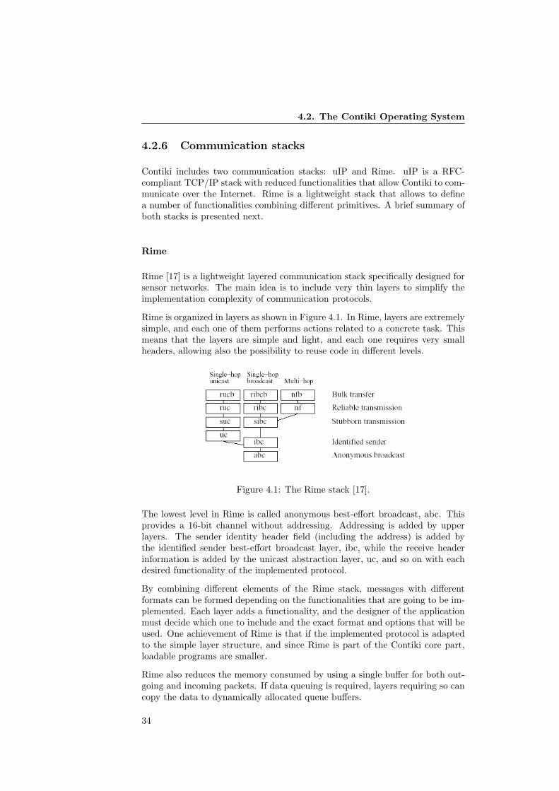
4.2. The Contiki Operating System
4.2.6 Communication stacks
Contiki includes two communication stacks: uIP and Rime. uIP is a RFC-compliant TCP/IP stack with reduced functionalities that allow Contiki to com-municate over the Internet. Rime is a lightweight stack that allows to definea number of functionalities combining different primitives. A brief summary ofboth stacks is presented next.
Rime
Rime [17] is a lightweight layered communication stack specifically designed forsensor networks. The main idea is to include very thin layers to simplify theimplementation complexity of communication protocols.
Rime is organized in layers as shown in Figure 4.1. In Rime, layers are extremelysimple, and each one of them performs actions related to a concrete task. Thismeans that the layers are simple and light, and each one requires very smallheaders, allowing also the possibility to reuse code in different levels.
Figure 4.1: The Rime stack [17].
The lowest level in Rime is called anonymous best-effort broadcast, abc. Thisprovides a 16-bit channel without addressing. Addressing is added by upperlayers. The sender identity header field (including the address) is added bythe identified sender best-effort broadcast layer, ibc, while the receive headerinformation is added by the unicast abstraction layer, uc, and so on with eachdesired functionality of the implemented protocol.
By combining different elements of the Rime stack, messages with differentformats can be formed depending on the functionalities that are going to be im-plemented. Each layer adds a functionality, and the designer of the applicationmust decide which one to include and the exact format and options that will beused. One achievement of Rime is that if the implemented protocol is adaptedto the simple layer structure, and since Rime is part of the Contiki core part,loadable programs are smaller.
Rime also reduces the memory consumed by using a single buffer for both out-going and incoming packets. If data queuing is required, layers requiring so cancopy the data to dynamically allocated queue buffers.
34
4. The Contiki OS and the Tmote Sky Platform
The code size of the layers is very small, and varies from 100 bytes of the ibc layer(identified sender best-effort broadcast) to 226 of the suc and ruc (stubborn andreliable unicast). Dunkels [17] describes some evaluation figures that prove theadvantages of using a low weight communication stack included in the operatingsystem core like Rime.
uIP
The uIP TCP/IP [15] communication stack was designed to allow small, memory-constrained 8-bit micro-controller based systems to communicate using the TCP/IPsuite. TCP/IP is one of the most used standard for communications, includingits usage in the Internet, it is clear the great advance that its implementationmeans for the WSN field. Enabling connectivity with Internet allows a numberof new applications and the improvement of existing ones.
The uIP stack is designed to comply only the absolute minimal set of featuresneeded for a TCP/IP basic communication. Such a reduced version is com-patible with most existing sensor nodes in the market. uIP includes reducedversions of IP, ICMP, UDP and TCP protocols. Contiki uses uIP as one of thecore communication stacks.
uIP is implemented as a main loop that checks if there are incoming packetsor if a periodic timeout has expired. If a packet has arrived, a function thathandles it is invoked. The function starts different actions depending on thedata carried by the incoming packet.
Periodic timeouts are used to launch TCP mechanisms depending on timers.Different timers are set depending on the actions performed by the node andthe requirements of the incoming packets. If as a result of the timer expirationdata packets are produced, they are sent using the regular uIP mechanism.
Given that the RAM memory is very reduced in the platforms where uIP isintended to be used, some TCP/IP mechanisms are not applied. Only one bufferfor both incoming and outgoing packets is implemented. Information stored insuch buffer cannot be overwritten by new incoming or outgoing packets, so theymust be processed immediately or stored in secondary buffers, depending on thememory capacity of the specific platforms.
uIP is a reduced version of the TCP/IP suite, and therefore not all the func-tionalities are included, although it complies the minimum requirements of thestandard. Complete information about the functionalities not implemented canbe found in the uIP reference documents [15].
4.3 The Tmote Sky Platform
The Tmote Sky is an ultra low power wireless module for use in sensor networks,monitoring applications, and rapid application prototyping. By using industrystandards, integrating humidity, temperature, and light sensors, and providingflexible interconnection with peripherals, Tmote Sky enables a wide range ofmesh network applications. It features the MSP430 microcontroller from Texas
35

4.3. The Tmote Sky Platform
Instruments and the CC2420 radio chip from Chipcon. Figure 4.2 shows aTmote Sky node.
Figure 4.2: The Tmote Sky node.
4.3.1 Microprocessor
The Tmote Sky features the Texas Instruments MSP430 F1611 microcontroller.The MSP430 is a low-power unit with 10kbyes of RAM, 48kbytes of flash mem-ory and 128 bytes of information storage. The processor consumes very lowcurrent for both active and sleep modes, allowing a battery lifetime of yearswithout replacing batteries. The internal digitally controlled oscillator allowsfrequencies of up to 8Mhz. Additionally, a 32kHz eternal oscillator is available.
A number of ports are available for different input and output signals, includingmonitoring of the battery voltage, UART, timers, etc.
Communication with host computer is performed using the USB port includedin the board. Tmote Sky nodes appear as COM ports, and if multiple nodes areconnected to the same computer, each one receives a different port identifier.The COM port can be read by an application, allowing the host computer toobtain output information generated by the node.
More detailed information is available in the MSP430 documentation availablein the MSP430 data sheet [4].
4.3.2 Radio
Tmote Sky nodes use the Chipcon CC2420 radio chip [5]. It is a IEEE 802.15.4compliant radio and provide the PHY layer and some MAC hardware-implementedfunctionalities. Reliable communication is achieved thanks to a high sensitivityvalue. The radio also features some low-consumption attributes that make it avery popular choice in many different node models based in the IEEE specifica-tion.
36
4. The Contiki OS and the Tmote Sky Platform
Different configuration options exist to achieve the best performance in differ-ent applications. Parameters like the RF channel or output power, the ClearChannel Assessment mode or different security options are programmed usingseveral configuration registers.
The radio chip is capable of performing some processing on both incoming andoutgoing packets that may simplify the software-based operations of the protocolstack implemented, such as address recognisation and filtering. Additionally,when a frame is generated, the synchronization header is automatically includedin the sent information, and upon reception it is automatically recognized andused for synchronization. The FCS, Frame Check Sequence is also automaticallyincluded in transmitted packets and verified by hardware. An option existsalso to automatically generate acknowledge frames following the IEEE 802.15.4specification, if the corresponding option bit is activated upon reception of anincoming packet.
CC2420 radio chip has a built-in RSSI (Received Signal Strength Indicator) thatprovides a digital value of the energy detected in the channel. This informationis used for the Clear Channel Assessment functionality that is employed by theCSMA-CA based transmission. This CCA information is available in a pin thatcan be accessed normally.
Tmote Sky features an internal antenna. It consists of a Inverted-F wire monopolewith the top section folded down to be parallel with the ground plane. The com-munication range is of 50 meters indoors and upwards of 125 meters outdoors.
37

4.3. The Tmote Sky Platform
38

Reducing the Energy Consumption of ZigBee with a Power-savingMAC Protocol5. Power Saving Mechanisms for WSN
Chapter 5
Power Saving Mechanismsfor WSN
5.1 Overview
Battery lifetime is one of the most important characteristics of a WSN. In orderto implement a sensor network for most applications described in section 2, thenodes must be capable of working for a time long enough without replacingbatteries. WSNs may be deployed in areas with difficult access, and replacingbatteries normally requires to halt the system activities. A combination ofextended lifetime and low costs open a wide range of possibilities and potentialapplications.
The objective of extending the lifetime of a node can be approached from differ-ent points of view. Nodes generally consist of a number of components, includinga microcontroller, a radio chip and other periferals. As described in previouswork [30], the most significant amount of power consumption is caused by ra-dio operations. Microcontrollers and other electronics components are generallydesigned with low consumption characteristics, and although technology pro-vides better results every day, reasonable improvements can only be achievedby minimizing the time that the radio spends either in transmit or receive mode.
The MAC layer controls how a node accesses the physical channel, either totransmit or to listen for possible incoming transmissions. At the MAC levela number of protocols have been designed to optimize the listening periodsscheduling. MAC protocols turn the radio off during some periods followingdifferent criteria. The protocols must also maintain the reliability of the com-munication links although the nodes are not constantly listening. Schedulingthe listen and sleep periods of the transceiver to be able to process all the trafficwhile saving power is the main design challenge of MAC protocols development.
Some of the most relevant proposed protocols are presented in this chapter,including X-MAC, which was chosen to improve the power-saving characteristicsof the ZigBee stack. Also, some other approaches to the objective of extending
39
5.2. Energy Waste
the battery lifetime are introduced, like power-aware routing or solar-powerednodes.
5.2 Energy Waste
The main causes of energy waste in WSNs have been described by Demirkolet al [14]. Given the characteristics of radio communications, the two mostimportant are idle listening and overemitting. Idle listening consists of havingthe transceiver active when no incoming packets are received, and overemittingconsists of having to repeat the transmission of a packet because the destinationnode is not listening. An active transceiver consumes the same amount of energyregardless if a transmission occurs or not. Therefore, energy is wasted becauseof the fact that a node can not be aware of when is it going to receive a packet.
If more than a frame is transmitted at the same time a collision occurs. Gener-ally, all collided packets must be retransmitted, therefore increasing the powerconsumption and the traffic load in the network. In cases with high traffic ratesand a poor scheduling mechanism this can become a major problem if more andmore packets must be retransmitted, worsening the characteristics of the wholesystem.
Another proposed reason of energy waste is overhearing, i.e., receiving packetsthat are destined to other nodes. Given that no filtering of incoming packetsoccurs until the MAC layer is reached generally is not possible to deal with thisproblem unless a mechanism is introduced that notifies all nodes in the area ofwhich one is the destination node of the next transmission.
This normally is achieved by transmitting control packets. These can be usedby a MAC protocol also for other tasks but they introduce energy waste as aresult of control packet overhead. Obviously, a MAC protocol should use theminimum possible number of control packets.
5.3 MAC Protocols Strategies
A MAC protocol decides when and how competing nodes access a to sharedmedium. In the event of a collision, a MAC protocol deals with it using a con-tention resolution algorithm. Basically, a MAC protocol can try to specificallyavoid such collisions by scheduling transmissions originated in different nodesso that they do not interfere with each other, or use a mechanism to detect thecollision and retry after a period of time. Therefore, MAC protocols can bedivided in two groups: synchronous or asynchronous.
5.3.1 Asynchronous protocols
Asynchronous protocols do not use any kind of time scheduling to avoid collisionsbetween different nodes in the network. This provides a lot of flexibility, andremoves the problem of having to synchronize independent clocks.
40
5. Power Saving Mechanisms for WSN
There are several approaches of this kind of protocols. The special characteris-tics of WSNs do not allow the use of some mechanisms applied in other kind ofsystems, like the RTS/CTS messaging used in the IEEE 802.11. The 802.15.4specification proposes the use of a simple backoff based contention access mech-anism. When a transmitting node detects a collision in the medium, it triesagain after a random period of time.
It is usual that this kind of protocols implement a duty cycle to sample thechannel waiting for incoming communications while spending most of the timesleeping. The idea is to transmit a preamble signal before a communicationbegins that is received by a node when it activates its radio. If such preambleperiod is longer than the sleep interval, the sender is guaranteed to be able totransmit to its target. There are different variations of this scheme, and themost efficient one is implemented in X-MAC [10].
Other more complex implementations require to use a second channel for sig-naling information. Obviously, this increases the cost of the hardware andthe power efficiency is compromised because of the operation of two differenttransceivers.
5.3.2 Synchronous protocols
Synchronous protocols schedule their transmission following different patternsso that different nodes do not attempt to transmit at the same time. Time isdivided into slots and nodes wake up at the beginning of each slot to transmitand receive information. A proper scheduling policy can allow the nodes to havea deterministic access to the medium with all the advantages it represents.
There are many possible allocations schemes. A central node can have authorityand regulate the channel access allocating slots to different nodes. A fixedframed structure can be used instead. This kind of system provide a naturalway to conserve energy. A node can turn off the radio during those slots inwhich it does not have to transmit or receive information.
The main problem of this kind of protocol is that it is required to have a reliabletime synchronization for all devices in the system. In a distributed system likea WSN, this is not a trivial task. Additionally, many allocation schemes arenot compatible with multi-hop networking or mesh topologies, and this kind ofprotocol generally can not handle topology changes or sudden change of trafficloads properly.
5.4 Proposed MAC Protocols
5.4.1 S-MAC and T-MAC
S-MAC (Sensor-MAC) [38] is based on locally managed synchronizations thatare used to schedule periodic sleep-listen periods. S-MAC allows to use differentlengths for each period in each node.
41
5.4. Proposed MAC Protocols
Because of the clock drift between different nodes, a mechanism is implementedthat allows the nodes to be able to inter-operate. Neighboring nodes periodicallyexchange relative time stamps, and they use this information to set up differentvirtual clusters. Nodes broadcast information about their schedules to all othernetworks, using special synchronization packets.
If multiple nodes want to transmit to the same destination, they must contendfor the channel. The same mechanism than the one proposed in the IEEE802.11 specification is implemented, using packets to request and acknowledgepermission to transmit.
It is possible that a node is within transmission range of other devices belongingto different virtual clusters. In such cases, the nodes must follow the schedulesof both clusters, meaning that the listen periods will be longer and the powerconsumption is likely to be higher.
Another important feature of S-MAC is the possibility of dividing long messagesinto frames that are sent in a burst. This way energy is saved by minimizingcommunication overhead. However, fairness is reduced and this can cause con-flict when adapting the protocol to already established standards like the IEEE802.15.4.
S-MAC is improved by adding an adaptive component to the duty cycle [13].The new protocol is denominated T-MAC. Basically, the listen period end isdetermined on the run by each node. As before, messages are sent in a burst,so when a node stops receiving packets it determines that the burst is over andtherefore returns to sleep. This way the duty cycle parameters vary dependingon the traffic load conditions.
The main drawback of this proposal is the increase of latency, and the fact thatthe optimal performance is achieved when information can be sent in a burst,so it is no suitable to use in a number of applications.
5.4.2 WiseMAC
WiseMAC protocol [21] uses preamble sampling to decrease idle listening. Thistechnique consists of the transmission of a preamble that precedes each datapacket to notify the receiving node that the sender is trying to communicatewith it.
Nodes sample the channel periodically. If a node starts listening and detectsthe channel busy (because of the preamble transmission), it remains in listeningstate until a data packet is received or the medium becomes idle again.
In WiseMAC, the length of the preamble is equal to the sampling period. Un-fortunately, WiseMAC does not prevent problems related with collisions, andalso at the end of the preamble the receiving node might not be ready. Further-more, the energy spent in transmitting the preamble and listening to packetseven when they are not destined for the node are also an important source ofenergy waste.
WiseMAC allows to determine the length of the preamble dynamically. Thenodes obtain information from its neighbors schedule. Information is refreshed
42
5. Power Saving Mechanisms for WSN
with every data exchange by attaching information in the acknowledgment mes-sage. With that information, the protocol schedules transmissions so that thesampling time of the receiver occurs during the preamble sequence sending.
5.4.3 TRAMA
TRAMA [31] consists of a classical TDMA scheme with improved energy ef-ficiency. In this protocol, for each time slot a node is designated transmitterwithin a two-hop neighborhood.
A time slot can be either random-accessed or scheduled-accessed. Random-accessed periods are accessed using a contention-based mechanism. These pe-riods are used to gather information about the two-hop topology of each node,and to determine the length of the transmission period required. This way, ev-ery node receives one time slot in which it has priority to transmit. Optionally,nodes can communicate that they are not going to use their time slot, allowingnon-owners to contend for the medium.
TRAMA presents longer sleep periods and less collision problems than regularCSMA, but on the other hand, a random access period is required to exchangeinformation. The protocol description requires the scheduled transmission pe-riod to be seven times longer than the random access period. Given that theradio is always active during the random access period in order to exchange theschedules information, and without considering transmissions in the scheduledtransmission period, this means that the duty cycle is at least 12.5%, consider-ably high in many cases.
5.4.4 B-MAC and Z-MAC
B-MAC [28] is a CSMA based protocol that implements an adaptive preamblesampling scheme to minimize idle listening in a similar way as WiseMAC. B-MAC uses low power listening (LPL) for low power communication.
Any node using LPL turns on the radio to check for activity. If it is detected, thenode stays on until an actual packet is received. Otherwise it returns to a sleepperiod to save energy. Prior to sending information, the sender node must senda preamble sequence to notify the surrounding nodes that it has information totransmit.
The preamble length must be equal to the period between channel samplings.In practice, this limits the maximum length of sleeping periods since the powerconsumption is related with the time that the radio is active sending the pream-ble, or after waking and detecting it, waiting for the actual packet.
The LPL mechanism implemented in B-MAC is not very efficient since a lotof energy is wasted because of overhearing and overemitting. The fact that anode cannot determine the target destination of a packet during the preambleperiod decreases the energy efficiency. This problem is addressed by X-MAC,improving the LPL mechanism.
43
5.4. Proposed MAC Protocols
Z-MAC [33] was developed by basically including a TDMA schedule to the B-MAC protocol in order to improve contention resolution. A time slot is assignedwhen the network is created using a distributed algorithm. The principle of thisnew implementation is that after the assignment, both owners and non-ownersof the time slots try to access the channel to transmit information.
The transmission procedure also begins with the preamble sequence. To priori-tize the owner nodes transmissions, they begin their preamble procedure beforenon-owners do. Therefore, if a non-owner accesses the channel and finds thata preamble was already started by the owner of the time slot, it aborts it owntransmission and tries again in the next slot. Optionally, Z-MAC can be config-ured so that only the owners of each slot can compete for the channel, in caseswith a lot of traffic involved.
5.4.5 X-MAC
X-MAC [10] is a duty cycled based MAC protocol that implements an improvedversion of LPL. As in the B-MAC and WiseMAC protocols, the sender transmitsa preamble that lasts at least as the sleep period of the receiver node. When thereceiver node detects the preamble, it stays awake waiting for the actual packetto arrive.
In the regular LPL mechanism like the one used in B-MAC, a significant amountof energy is wasted as part of the process. The transmitter always has to com-plete a preamble transmission during all the sleep period of the duty cycle,independently of when does the target node actually activates its radio. Logi-cally, the same problem affects the receiver node, since it must keep the radioactive in listen mode until the preamble is completed before the actual packet isreceived. Furthermore, nodes that are not the destination of the communicationstarted by the sender also detect the preamble and stay awake since they cannotdetermine if they are the destination of the actual packet.
X-MAC introduces simple changes in the LPL procedure that removes thesesources of waste in terms of energy consumption. This is achieved by includinginformation about both the sender and the receiver of the upcoming packetin the preamble, and by sending a special acknowledgment packet back whenthe target node receives the preamble packet and is ready to receive the actualframe. The sender, upon reception of that acknowledgment, halts the preamblesequence transmission and sends the actual packet.
Attaching an identifier of the transmitter and target nodes of a communicationin a preamble packet can be achieved by including the short address field ofboth nodes, or any other acceptable identify parameter
For the protocol to function correctly, between the short preamble packets shortpauses must be introduced, during which the transmitter turns the radio on tolisten mode waiting for the preamble acknowledgment to arrive. If no suchpacket is received after a short period of time, then a new preamble packetis transmitted and so subsequently, creating a strobed preamble. Figure 5.1depicts the transmission procedure in detail.
44

5. Power Saving Mechanisms for WSN
Figure 5.1: X-MAC transmission and reception mechanisms [10].
Buettner et al [10] also propose an adaptive mechanism to determine the optimalvalues for the duty cycle scheme in terms of minimizing the power consumptionwhen transmitting or receiving packets. This is based in a mathematical esti-mation of the power consumption. The following expressions [10] represent theexpected energy to send and receive a packet
Es = PTxSp + PRxSal)(1/(Rl − Sp)/(Rl + Rs)) + SdPTx
=(PTxSp + PRxSal)(Rl + Rs)
Rl − Sp+ SdPtx (5.1)
Er =(PsRs + PRxRl)
1− (1− Pd(t))(Rl+Rs)+ PTxRa + RdPRx (5.2)
In the two previous expressions, Pd(t) represent the probability of receiving apacket in any given interval. PTx and PRx are the radio power consumptionin transmit and receive modes. Ps is the power consumption in sleep mode.Sp,Sal and Sd denote the duration of the sender’s preamble, acknowledgmentlisten and frame transmission periods. Rl and Rs denote the receiver sleep andlisten periods.
The paper proposes to perform a linear interpolation, by computing a numberof optimal Rl and Rs values. During the node operation, the traffic load canbe estimated online, so the duty cycle scheme can be dynamically modified.However, given that it is a requirement that all nodes implement the sameduty cycle and since different nodes can detect different amounts of traffic, thehigher layers must coordinate the adaptive mechanism so that every device inthe network uses the same duty cycle parameters.
X-MAC was chosen because of its simplicity and its versatility. Since no timesynchronization schemes are introduced, clock drift problems are not present. Itsadaptability and the mathematical description provided make a very interestingchoice to develop power efficient solutions for mesh network topologies. X-MACwas implemented in Contiki and introduced as a MAC protocol for the ZigBeestack. The details concerning the implementation and the results obtained arepresented in later chapters of this report.
45

5.5. Other Approaches
5.5 Other Approaches
MAC protocols improve the devices performance greatly, but extending the bat-tery lifetime to an acceptable level to start considering a WSN a semi-permanentsolution cannot be achieved by simply implementing these techniques.
There are other approaches that can also extend the battery lifetime of a WSN.Depending on the case, they can be used independently or combining them withthe use of MAC protocols to obtain an integral solution to extend the batterylifetime. These include methods like power aware routing [27], solar-poweredhardware [25] or new coding schemes that optimize the energy consumption [39].
46
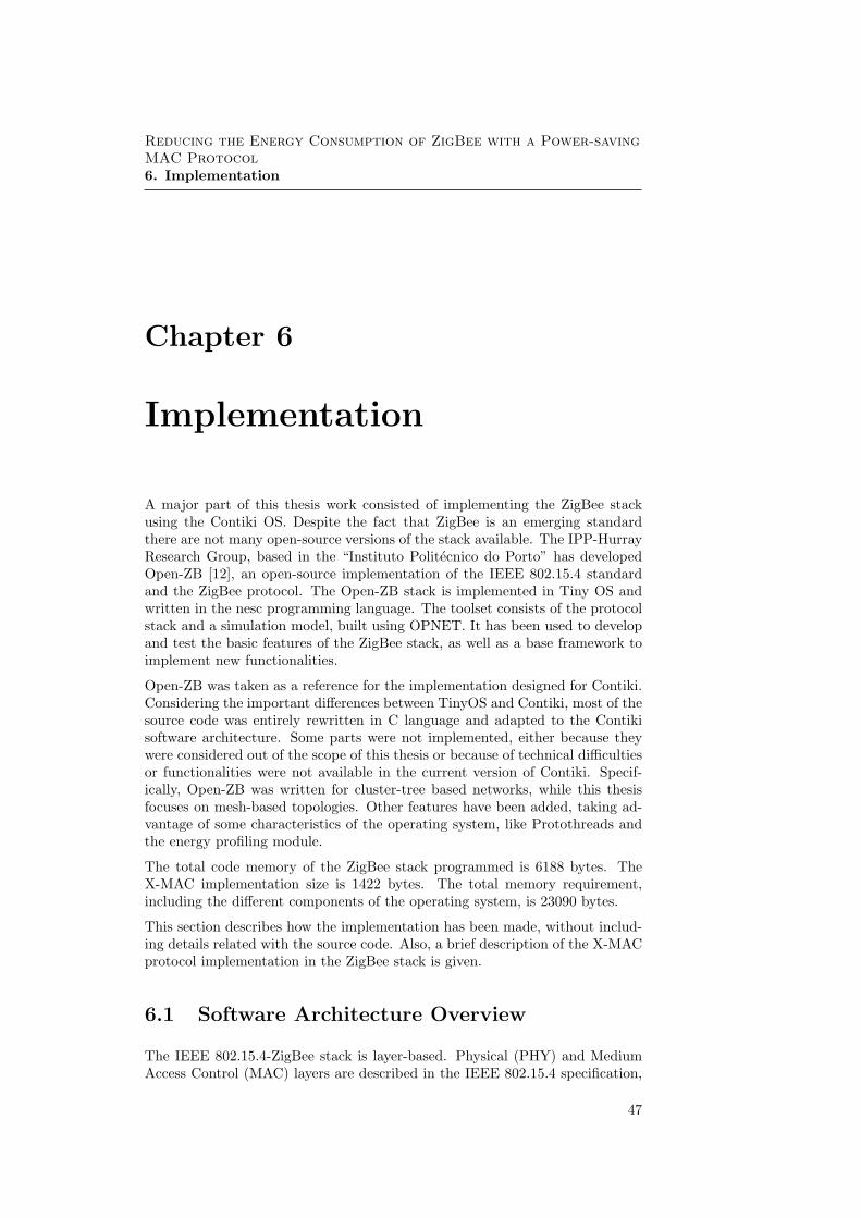
Reducing the Energy Consumption of ZigBee with a Power-savingMAC Protocol6. Implementation
Chapter 6
Implementation
A major part of this thesis work consisted of implementing the ZigBee stackusing the Contiki OS. Despite the fact that ZigBee is an emerging standardthere are not many open-source versions of the stack available. The IPP-HurrayResearch Group, based in the “Instituto Politecnico do Porto” has developedOpen-ZB [12], an open-source implementation of the IEEE 802.15.4 standardand the ZigBee protocol. The Open-ZB stack is implemented in Tiny OS andwritten in the nesc programming language. The toolset consists of the protocolstack and a simulation model, built using OPNET. It has been used to developand test the basic features of the ZigBee stack, as well as a base framework toimplement new functionalities.
Open-ZB was taken as a reference for the implementation designed for Contiki.Considering the important differences between TinyOS and Contiki, most of thesource code was entirely rewritten in C language and adapted to the Contikisoftware architecture. Some parts were not implemented, either because theywere considered out of the scope of this thesis or because of technical difficultiesor functionalities were not available in the current version of Contiki. Specif-ically, Open-ZB was written for cluster-tree based networks, while this thesisfocuses on mesh-based topologies. Other features have been added, taking ad-vantage of some characteristics of the operating system, like Protothreads andthe energy profiling module.
The total code memory of the ZigBee stack programmed is 6188 bytes. TheX-MAC implementation size is 1422 bytes. The total memory requirement,including the different components of the operating system, is 23090 bytes.
This section describes how the implementation has been made, without includ-ing details related with the source code. Also, a brief description of the X-MACprotocol implementation in the ZigBee stack is given.
6.1 Software Architecture Overview
The IEEE 802.15.4-ZigBee stack is layer-based. Physical (PHY) and MediumAccess Control (MAC) layers are described in the IEEE 802.15.4 specification,
47

6.1. Software Architecture Overview
while Network (NWK) layer is described in the ZigBee specification, as well asthe Application (APL) layer.
Implementing a multi-layered protocol is always a complex challenge. The waydifferent levels work and interact is highly dependent on the protocol specifica-tion and the operating system characteristics. Having different levels communi-cating with each other, embedding them in a global application or implementingthe multi-layered structure in any other way is a crucial aspect of any protocolstack software architecture.
Given that Contiki supports multiple independent processes, a natural approachconsists of programming one for each entity or service described in the protocolspecification. This way, the implementation would follow the protocol descrip-tion in all aspects, such as the clear differentiation of the different layers andthe use of almost the same primitives to communicate between them. It wouldalso be easy to add or modify parts of the code, since the different processeswould have independent structures and the whole stack would be highly mod-ular. Figure 6.1 depicts the structure of this approach for the ZigBee stack.
Figure 6.1: Proposed software architecture.
In this structure, threads communicate only by passing messages in the formof event posts. There are no callback functions, and the distinction of thedifferent entities of the protocol is clear. The processes consist of a loop thatwaits until an event is posted. That would represent that either the higheror the lower layer requested an action from the process. This event mightrepresent, for example, that an incoming frame has been received, that the nextupper layer wants to send a packet, or that a change in different configurationparameters controlled by the process is required. After completing the required
48

6. Implementation
action, the process would go back to a yield status until next event occurs.This means that, for a typical action like sending a packet, a number of inter-process messages are required, since the operation consists of several steps that,following the specification, are carried out at several levels. These include forexample checking that the channel is free, turning the radio on, passing eachlayer payload to the next lower layer and adding headers, etc. In this case thisinvolves different threads.
It is important to remark that in Contiki, a process must release control, oryield, so that other threads can perform its assigned actions. In many cases, fortasks that require operations at different layers, a running process must post anevent to the process that is supposed to run immediately after and then sleep,so that the different steps are taken in the right order. The message sent usingthe process post mechanisms can include information, such as parameters to beused by the next higher or lower layer or data payloads.
For example, if the MAC layer has a data frame to transmit, the transmissionprocess would follow the sequence depicted in Figure 6.2.
According to the procedure depicted in the next page, the MCPS process wakesup when the transmission request is received. Subsequently, each phase of theprocess is carried out. For each request to the PHY layer, an event to theappropriate process is issued. The MCPS process blocks until the responsefrom the lower layer is received, also via a posted event. Therefore, sending aframe requires 17 events posts.
Despite the fact that this solution presents advantages in terms of modularity,it also presents important flaws. Basically, the inter-process communication us-ing event posting requires too much time (around 2000 cycles compared to 4cycles required to call a function). In applications with very strict synchroniza-tion requirements, this represents a major problem, especially considering thatmany events can happen almost simultaneously, and that most actions requirea number of steps and events posts. This would make the implementation ex-tremely inefficient, since most of the time used by the CPU would consist ofposting events to yield immediately afterward. Additionally, if several actionsoccur at the same time, an extremely complex code would be required in or-der to successfully handle the different steps of different processes, given thecharacteristics of protothreads.
This stack was partly developed, and it became evident that the proposed struc-ture was not suitable because of the problems described above.
A different approach was considered, focusing on the functionality more than thelayered structure of the protocol specification. The new architecture relies oncallback functions: The different layers of the protocol stack are all implementedusing functions that are called when the action that is being realized requiresso.
In this case, the separation of the different layers is not so strict. There arenot different processes implementing different layers, instead the functions areavailable to any process being run. However, it remains clear which functionsimplement tasks corresponding to the different layers, and the source code atone level can be modified without altering the behavior of the other ones so theimplementation can still be considered modular.
49
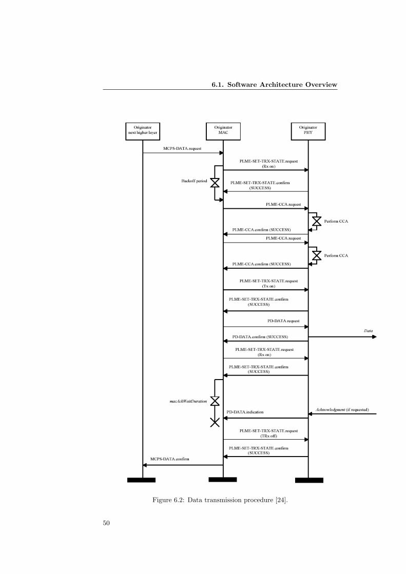
6.1. Software Architecture Overview
Figure 6.2: Data transmission procedure [24].
50
6. Implementation
The implementation designed focuses in testing the protocol performance indifferent cases. Therefore, above the network layer, an Upper Layer processwas introduced, to control the experiments in each case. That Upper Layercan be considered as a substitute for the application layer, since no other ap-plication services are required to perform the experiments and check the powerconsumption of the stack. It basically consists on a process that schedules packettransmissions depending on the scenario. This is the only process executed thatdoes not belong to the Contiki OS kernel.
Perhaps one of the most important differences is the way incoming and outgoingpackets are handled. In this case, when the radio chip detects an incomingframe, an interrupt signal is handled by a function that simply calls a predefinedfunction, which is part of the MAC protocol implemented in each case. A MACprotocol is defined as a Contiki service, that specifies the functions that shouldbe called depending on the event that must be handled. More information canbe found in the MAC layer subsection.
After this introduction to the software architecture, a deeper description of theimplementation is given, focusing on the most important functionalities andprocedures in the different layers.
6.2 ZigBee Stack Implementation
6.2.1 Functionalities Implemented
The current version implements a simplified version of the CSMA/CA mech-anism, both direct and indirect transmission mechanisms, the construction offrames and information recovery from incoming frames. Several types of framesare defined, like ACK frames or command frames.
Mechanisms like association, network creation or route discovery are also in-cluded. Information bases of the different layers are defined, and can be modifiedusing different functions.
There are also some functionalities not implemented, such as the beacon-basedtransmission scheme, the channel scan process, and the application layer speci-fications.
6.2.2 Contiki main thread
Every application that runs under Contiki starts with a main thread that ini-tializes and configures most hardware and software components that are used.Different calls to different functions perform the initialization of the componentsusing the parameters specified in the main function. Also, the user can choosewhat MAC protocol to initialize. Several internal processes required by differentelements of the operating system (such as timers or sensors) are started. Usersprocesses are also started and afterwards, the main-thread enters a loop waitingfor events or interrupts to occur.
51
6.2. ZigBee Stack Implementation
6.2.3 Application layer
The ZigBee specification defines the Application layer as three different compo-nents:
• The Application Support Sublayer (APS).
• The ZigBee device objects (ZDO).
• Manufacturer defined application objects.
Since the APL layer is the closest to the application developed for differentpurposes, it has not been developed for the current stack, since the developmentof a specific application was out of the scope of this master thesis.
Instead, a simple application process was developed in order to control andperform the different experiments that were carried out to test the reliability andperformance of the stack written. This Upper Layer (UL) is located above theNWK layer, and it employs the lower layers elements like a regular applicationprocess.
The UL is defined as a Contiki process that works independently from therest of the system, but that makes use of the available stack functions. Thesefunctions can notify events such as incoming frames. Apart from the usualinitialization tasks at the beginning of the program, the Upper Layer processschedules outgoing frames at different rates depending on the experiment that isbeing carried out. Frames are generated upon completion of countdown timers.The process is generally blocked until a packet is scheduled, or until an incomingframe wakes it up in order to process the received information.
An auxiliary application designed to store and recover information concerningpower consumption and latency in scenarios in which the nodes are not con-nected to a computer is also controlled from the UL process. This is achievedby storing the information in a file kept in the Tmote Sky platform memory.
Replacing this simple application for others developed for certain purposes canbe done without altering the structure of the stack, since this UL employs thelower layers in the same way than a normal application would do.
6.2.4 Network layer (NWK)
The ZigBee NWK Layer functionalities controls the correct operation of theIEEE 802.15.4 MAC layer and provide a service interface to the applicationlayer. The network services include the generation of frames to transport theapplication layer PDUs to an appropriate device, either the final destinationor the next destination in a multi-hop communication. The network layer alsocontrols a number of network management tasks, such as establishing new net-works, joining and leaving networks, neighbor and route discoveries, etc.
The NWK layer is implemented using a number of functions that are employedto manage different elements, in which the routing information and the other
52
6. Implementation
network layer data are stored. These elements are the NIB, network layer in-formation base, and a number of tables in which routes, neighbor nodes speci-fications, etc, are kept for each node.
In order to complete a number of actions related with network managementoperations, such as route or neighbor discovery, requests to join, etc, the NWKlayer makes use of the MAC functionalities, issuing command frames that aretransmitted using the procedures explained in the MAC implementation sub-section. Sending and receiving network command frames makes no difference atthe MAC level with any other kind of transmitted information, since the MAClevel considers the network frame as part of the MSDU or MAC level payload.
An important amount of the network layer information is stored in three differ-ent tables: The neighbor table, the routing table and the route discovery table.They are implemented as arrays of a fixed number of elements with the differentfields described in the specification.
The routing table contains information for each possible destination node aboutthe next-hop address in the route as well as some other information concerningthe status of the link. This is implemented using a element defined as rout-ing table element, that contains the destination and next-hop addresses as wellas a control byte.
The route discovery table is only used in the route discovery process, and storessome temporary information. It contains both source and sender addressesfields, an identifier and, according to the specification, a countdown timer. Theaddresses fields and identifier are implemented as regular elements in the de-fined type route discovery element. The countdown timer is not properly im-plemented yet, the present version simply sets a timeout timer when any routediscovery starts, but in the future a more appropriate solution will be includedso that each route discovery has its own timer.
The neighbor table of each node contains information on every device withintransmission range. According to the specification, some of the informationfields included in this table are related with the beacon-based transmissionmechanism. Since this implementation does not include such functionality, thesefields were removed in order to save memory. The fields implemented includeboth the extended and network addresses fields, information about the neighbordevices capabilities, etc.
Both the NIB and the described tables contain all the required information ofthe NWK level of a ZigBee-based network. Several functions exist to performdifferent actions, most of them taking the contents of such tables either as inputor as a target to obtain or update new information.
An important function of the NWK layer is to provide routing capabilities tothe nodes. When an incoming frame is received, the MAC header containsa destination address field that must be either the node own address or thebroadcast address for the frame to be processed by the NWK layer. If thisis the case, the NWK header also includes an address field, determining thefinal destination of the payload included in the frame. If the node is the finaldestination and it is a data frame, the next higher level is notified. If it is thefinal destination and it is a command frame, the required action is performed
53

6.2. ZigBee Stack Implementation
and, depending on the specific action and the options selected, notified back tothe original sender. If the node is not the final destination, the node checks itsrouting table to determine if the final address is included. If so, a new frameis generated using the next-hop address of the routing table as the next MAClevel address, and the frame is sent following the procedure described in thelower levels implementation details.
The route discovery procedure has also been implemented. When a processstarts the procedure to discover a route to a new device, a flag is activatedand a route request command frame is broadcasted to all surrounding nodes,using the MAC layer services as described in the specification. Route discoverytable and routing table entries are created, and a timer is set. When a routediscovery frame is received, the process route discovery function is called. Thefunction checks if the node is the target of the discovery frame. If so, the nodeautomatically records a route entry to for the originator device, and issues aroute discovery response frame to the originator. Otherwise, the intermediatedevices also create a route discovery table and a routing table entries, sets atimer and re-broadcast the frame. Eventually, a response frame will be received,and the new route information will be stored or updated, or the route discoverytimer will expire. In the current version, all nodes are assumed to have routingcapacity.
6.2.5 Medium access control layer (MAC)
The IEEE 802.15.4 MAC layer is responsible for implementing a number of func-tions related with the use of a MAC protocol as well as other dealing with thecontrol of the physical layer. The IEEE standard defines two possible options:a beacon-based MAC protocol, and a CSMA-CA MAC protocol. Given that,no beacon protocol is included in this implementation, and since the channelassessment is performed by the physical layer (as mentioned in the PHY layerdescription), the MAC layer deals mostly with frame generation and recovery ofpayloads and header fields, as well as acknowledgment control. A version of theX-MAC protocol has been developed and introduced in the ZigBee stack (seesection 6.3).
The access to the medium in order to transmit or receive information actuallybegins in the MAC level. For the outgoing packet case, when a higher layer hasinformation to send, the MAC level creates a frame and requests the physicallevel to transmit it. When an incoming frame is detected in the medium, aninterrupt signal is handled by a function that calls a predefined function that ispart of the MAC protocol implemented. A MAC protocol consists of a Contikiservice that defines a number of functions that handle different events and op-erations related with the medium access. In the read case, the MAC functionaccesses the information received by the radio device by using the next-lowerlevel (PHY) driver, that also defines a function that recovers information fromthe FIFO buffer. That information is later processed in the MAC level.
The MAC protocol defines the procedures to access the medium when there isinformation to transmit. In the most simple case it simply passes the outgoingpacket to the physical layer and the transmission is performed immediately.
54

6. Implementation
More complex protocols can include a time scheduling algorithm or performseveral preliminary actions, like the TDMA or the X-MAC cases. The resulthowever is always the same: A frame generated by the node is transmitted, oran incoming packet is read and processed. The rest of the stack is independentfrom the MAC protocol used, so it can be easily replaced. The MAC protocolis declared and initialized in the Contiki main thread.
The outgoing and incoming frames are treated in a very different way before orafter being processed at the physical level. To start with, in the incoming packetcase, when a sequence of bits is received in the MAC level, it is unknown whattype of frame is it, and therefore the structure and the layout of the sequenceof bytes stored in the buffer is unknown. Depending on the frame type, and onthe different options included in the frame header, the MAC layer must takedifferent actions and the next higher layer will be notified in different ways.
Once the incoming information has been stored in the buffer, the function pro-cess incoming mpdu is called to recover the MAC level information. The maingoal of this step is to obtain the MAC frame header values and MAC payloador MSDU, departing from the physical payload or PSDU that was obtained inthe physical level processing of the incoming packet. The function receives thenumber of received bytes as a parameter. Figure 6.3 shows the general MACframe format.
The first thing that the function determines is the type of incoming frame in thebuffer, which is determined in the frame control field of the MAC header. Read-ing the first byte and storing it provides that information, so further processingis done depending on the type of received frame.
Figure 6.3: General MAC frame format [24].
The frame control field also includes information about the address type used.As was described in a previous section, there are two addressing modes in a IEEE802.15.4 based network: 64 bits IEEE addresses, or 16 bits short addresses. Also,in some cases, the source address field may not be present. The fact that anincoming message can implement the addresses in any mode and that it is notknown beforehand makes the incoming packet processing a bit tricky. However,reading the frame control field before actually processing the rest of the frameprovides enough information about the format of the bytes in the buffer as tofill the different fields and recover the payload.
After learning about the frame type and the address fields mode, the appropri-ate function is called to recover the rest of parameters of the MAC level header.
55
6.2. ZigBee Stack Implementation
There exists one function for each possible format, based on the possible com-binations of addresses field types. These functions read the buffer byte by byte,assigning values to the different fields of the headers depending on the formatestablished in the frame control field. The payload is also copied to anotherbuffer, so it can be accessed by the next upper layer. Also, if the correspondingfield of the incoming header determines that a acknowledgment is expected inthe source node, one ACK frame is automatically generated and sent beforefurther processing the incoming information, according with the IEEE 802.15.4specification.
After the MAC header and payload are recovered from the read buffer, thenode checks the destination address field of the received frame. If the addressfield is not the node address or the broadcast address, the frame is discarded.Otherwise, the next upper layer is notified of the incoming packet in differentways depending on the type of the received frame. This notification to the nexthigher layer is performed as a function call. Different command frames havedifferent functions to perform the desired action. If a data frame is received,the MAC payload is stored in a different buffer that is accessed by the NWKlayer.
The sending procedure in the MAC level is similar to the reception, but work-ing in the reverse direction. The MAC layer receives a series of transmissionoptions and a payload, and must create a frame with the format described inthe specification that is passed to the physical level for the actual transmission.The create mpdu function is called when a data frame is to be created. Theinput parameters are a number of options that determine the parameters of thetransmission as well as the format and the contents of the frame. Accordingto these parameters, the frame is created and stored in the send buffer. After-wards, the MAC protocol is notified that a frame must be sent and dependingon how the protocol schedules transmissions, a different procedure occurs untilthe frame is actually sent using the PHY layer as described before.
If the transmission options indicates that the next upper layer requires an ac-knowledgment, a timer is set when the frame is generated, programmed to expireafter a timeout period has expired. If no ACK frame is received in that timeperiod, the next upper layer is notified, and if an ACK is received the timerstops. The next higher layer decides which actions should be taken, dependingon the frame type and other parameters.
An important part of the MAC layer is referred to the implementation of theMAC protocol. As was stated before, the IEEE 802.15.4 presents a beaconbased protocol that is not suitable for the mesh-based networks that are themain subject of this thesis. In a later subsection the details about the X-MACimplementation that was built above the PHY layer are presented.
6.2.6 Physical layer (PHY)
The physical layer is the closest to the medium, and basically deals with the acti-vation and deactivation of the radio transceiver, the energy detection and chan-nel assessment, and sending and receiving data through the physical medium.
56

6. Implementation
This is the level that is more dependent of the hardware, since an importantpart of the level functionality require access to hardware registers and buffers.
Because of simplicity reasons, most of the physical level implementation is basedin the CC2420 radio driver included in the Contiki OS. The driver is a Contikiservice that defines a number of function that handle different operations. In thephysical level case, this acts as an interface for the MAC layer. After a deviceinitialization function (called by the Contiki main thread) has completed itstasks (setting default parameters such as the physical channel, the transmissionpower and other transmission options), a process is started that yields, passingcontrol to other processes of the system. When a packet is detected in the radiomedium, the interruption function calls the MAC driver read function, and thatone polls the process. When the process wakes, a function that reads the FIFObuffer is called, and after completing its operations the information is stored ina buffer.
The PHY layer implements two buffers to store the frames before being trans-mitted or after being received. There is one buffer for the outgoing packets andanother one for the incoming packets. The MAC layer stores its payload andheader in the send buffer for the PHY layer to copy it to the FIFO buffer ofthe radio chip. When a packet is received, it is copied to the read buffer for thehigher layers to access the information.
The read function in this case is the simple cc2420 read, as defined by the driverservice. This function basically accesses the value of the incoming packet length(the first byte of any incoming packet after the preamble) and stores the physicallevel payload in the read buffer. An automatic check of the preamble and footersequences is performed to validate the integrity of the received packet. Whenthe physical reception is completed, the information can be accessed from theupper layer in the buffer. The read function also returns the payload lengthvalue.
The other main function in the physical level is simple cc2420 send. This func-tion receives the physical level payload to be transmitted (stored in the sendbuffer), and the outgoing packet total length. Before actually sending the infor-mation to the physical channel, the send function performs a CCA operation tocheck if the channel is clear. This is one of the features of the radio chip. If thechannel is available, the physical payload is copied in the FIFO buffer, and thelength as well as the preamble sequence and the footer are automatically addedbefore sending.
There are other functions that implement other functionalities and that can beaccessed by the next higher layer to control different parameters of the radiotransceiver. Apart from turning the radio on and off, all the parameters of thePhysical Information Base (PIB) can be modified using functions included inthe physical driver. Also, the CC2420 registers can be manually modified.
6.3 The X-MAC Protocol Implementation
The X-MAC implementation was perhaps the most important challenge of thepresent thesis work. The NES group at SICS has been working with an initial
57
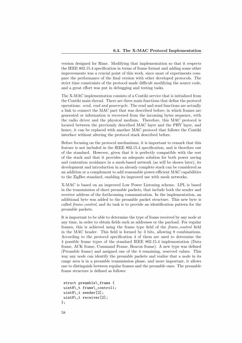
6.3. The X-MAC Protocol Implementation
version designed for Rime. Modifying that implementation so that it respectsthe IEEE 802.15.4 specification in terms of frame format and adding some otherimprovements was a crucial point of this work, since most of experiments com-pare the performance of the final version with other developed protocols. Thestrict time constraints of the protocol made difficult modifying the source code,and a great effort was put in debugging and testing tasks.
The X-MAC implementation consists of a Contiki service that is initialized fromthe Contiki main thread. There are three main functions that define the protocoloperations: send, read and powercycle. The read and send functions are actuallya link to connect the MAC part that was described before; in which frames aregenerated or information is recovered from the incoming bytes sequence, withthe radio driver and the physical medium. Therefore, this MAC protocol islocated between the previously described MAC layer and the PHY layer, andhence, it can be replaced with another MAC protocol that follows the Contikiinterface without altering the protocol stack described before.
Before focusing on the protocol mechanisms, it is important to remark that thisfeature is not included in the IEEE 802.15.4 specification, and is therefore outof the standard. However, given that it is perfectly compatible with the restof the stack and that it provides an adequate solution for both power savingand contention avoidance in a mesh-based network (as will be shown later), itsdevelopment and introduction in an already complete stack can be considered asan addition or a complement to add reasonable power-efficient MAC capabilitiesto the ZigBee standard, enabling its improved use with mesh networks.
X-MAC is based on an improved Low Power Listening scheme. LPL is basedin the transmission of short preamble packets, that include both the sender andreceiver address of the forthcoming communication. In the implementation, anadditional byte was added to the preamble packet structure. This new byte iscalled frame control, and its task is to provide an identification pattern for thepreamble packets.
It is important to be able to determine the type of frame received by any node atany time, in order to obtain fields such as addresses or the payload. For regularframes, this is achieved using the frame type field of the frame control fieldin the MAC header. This field is formed by 3 bits, allowing 8 combinations.According to the protocol specification 4 of them are used to determine the4 possible frame types of the standard IEEE 802.15.4 implementation (Dataframe, ACK frame, Command Frame, Beacon frame). A new type was defined(Preamble frame) and assigned one of the 4 remaining, reserved values. Thisway any node can identify the preamble packets and realize that a node in itsrange area is in a preamble transmission phase, and more important, it allowsone to distinguish between regular frames and the preamble ones. The preambleframe structure is defined as follows:
struct preamble\_frame {uint8\_t frame\_control1;uint8\_t sender[2];uint8\_t receiver[2];};
58

6. Implementation
The X-MAC protocol defines an adaptive duty cycle schedule. This is imple-mented with the powercycle function. It consists basically of a loop includedin a protothread, that periodically blocks and is resumed after the expirationof a timer. The loop controls the duty cycle by checking several flag variablesand turning the radio on and off. Right after starting one of the periods ofthe duty cycle (either the sleep or the listen period), the transceiver is in theappropriate state, and the protothread yields since the powercycle function isno longer needed until a timer, with the value of the current duty cycle phaseperiod, expires. It is important to remind that this function does not controlthe transmission or reception of data, only the radio status scheduling accord-ing with the duty cycles parameters. A basic scheme of the powercycle loop isdescribed in Figure 6.4.
while(1) {if(we_are_sending) {PT_WAIT_UNTIL(transmission_complete);}radio->off;set_timer(xmac_off_time);PT_WAIT_UNTIL(timer_expires);...if(we_are_sending) {PT_WAIT_UNTIL(transmission_complete);}radio->on;set_timer(xmac_on_time);PT_WAIT_UNTIL(timer_expires);}
Figure 6.4: X-MAC powercycle basic scheme.
In the listen periods, the radio is on, meaning that a node is able to detecttransmissions in the medium. Generally, if a packet is detected in the air, itis likely to be a preamble packet, since the protocol specifies that a number ofthese are sent prior to the transmission of the actual packet. As always, if apacket is detected, the interrupt will cause the call to the read function.
If the node is the destination of the preamble packet, a flag is activated toprevent the powercycle function to turn the radio off if the listening periodsuddenly ends. Immediately after receiving the preamble packet, a preambleacknowledgment (with the same format as the preamble frame) is sent, so thatthe sender realizes that the destination node is listening and waiting for theactual packet to be transmitted. That frame will be received shortly afterward,and the process incoming mpdu function is called, beginning the processing ofthe frame in the MAC layer, as was previously described.
If a node overhears a preamble targeted to another node, then it is aware thatthe sender is trying to communicate with a different target. In order to saveenergy the radio is immediately turned off in this case, since the node shouldnot expect any message during or immediately after the transmission of anotherframe. Additionally, a flag indicating this situation is turned on to indicate
59
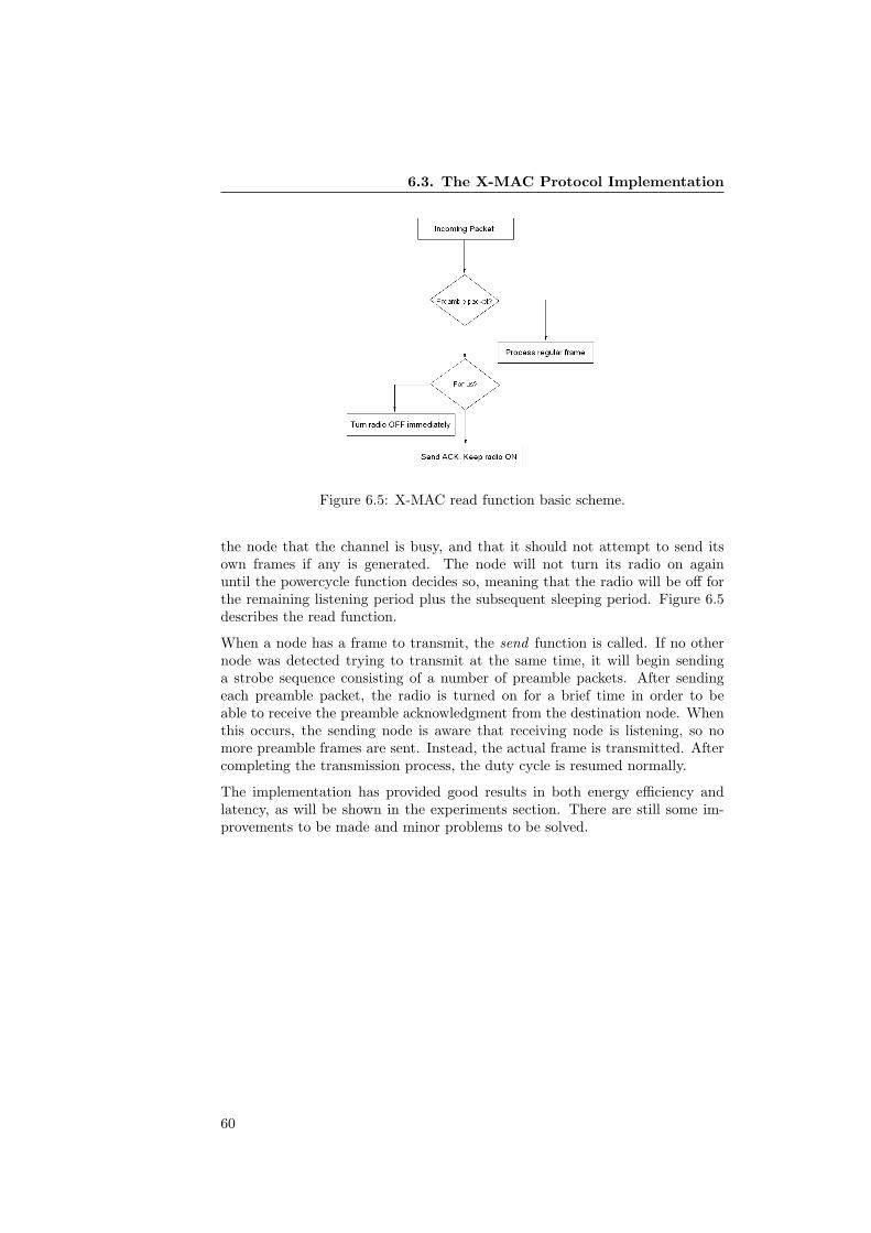
6.3. The X-MAC Protocol Implementation
Figure 6.5: X-MAC read function basic scheme.
the node that the channel is busy, and that it should not attempt to send itsown frames if any is generated. The node will not turn its radio on againuntil the powercycle function decides so, meaning that the radio will be off forthe remaining listening period plus the subsequent sleeping period. Figure 6.5describes the read function.
When a node has a frame to transmit, the send function is called. If no othernode was detected trying to transmit at the same time, it will begin sendinga strobe sequence consisting of a number of preamble packets. After sendingeach preamble packet, the radio is turned on for a brief time in order to beable to receive the preamble acknowledgment from the destination node. Whenthis occurs, the sending node is aware that receiving node is listening, so nomore preamble frames are sent. Instead, the actual frame is transmitted. Aftercompleting the transmission process, the duty cycle is resumed normally.
The implementation has provided good results in both energy efficiency andlatency, as will be shown in the experiments section. There are still some im-provements to be made and minor problems to be solved.
60

Reducing the Energy Consumption of ZigBee with a Power-savingMAC Protocol7. Evaluation
Chapter 7
Evaluation
To determine the performance of the X-MAC protocol implementation writtenfor Contiki, modified to be compatible with the IEEE 802.15.4 packets in thephysical medium, a number of experiments were carried out. The objective ofthese experiments is to quantify the power consumption on a number of TmoteSky nodes in different scenarios and using different parameters.
IEEE 802.15.4 provides two different alternatives of MAC protocols that couldbe chosen to compare X-MAC with. The first MAC option employs a regularCSMA-CA scheme to deal with collisions in the channel. This system how-ever does not provide good power-saving performance, since radio is active allthe time (unless the application layers decides to turn it off) and no controlmechanism exists to reduce power consumption using synchronization or dutycycling.
A superframe-TDMA based system is also supported. Using this mode thepower-saving capabilities of the standard are enabled. One node in the net-work is designated Coordinator, and sends beacons to synchronize the rest ofnodes. Communication is scheduled in a TDMA based scheme using the bea-con as a reference. This mechanism is specially appropriate for certain kinds oftopologies, like the cluster-tree or the star distributions, but not for the meshtopology.
TDMA-based schemes are not suitable to be implemented in mesh-networkswithout additional functionalities. Specifically, the IEEE 802.15.4 beacon-basedMAC protocol does not support a mesh-network topology. This is the X-MACimplementation is compared with the CSMA/CA, since it is the only availableoption of ZigBee for mesh networks.
The main goal of developing a new MAC protocol for the ZigBee stack is toobtain a solution that is energy-efficient as well as suitable to be implementedin a mesh-based network. X-MAC was chosen for this purpose. To determinethe performance of the new protocol, X-MAC has been compared with a MACprotocol implemented in Contiki named NULLMAC. NULLMAC consists of a100% duty cycle scheme. As can be expected, the power consumption for anydevice using this option is extremely high, and battery lifetime is estimated tobe only a few days. NULLMAC is very similar to the CSMA-CA protocol in
61
7.1. Technical and Practical Aspects
the ZigBee specification, and given that the topology that is being implementedis mesh-based, it is the only available option in the regular ZigBee standard.
This section describes the experiments designed to evaluate the X-MAC pro-tocol performance. An introduction on the energy estimation module includedin Contiki is provided. Some other practical aspects of how the experimentswere performed are also included. The results presented show that a significantquantity of energy can be saved by implementing X-MAC, extending the batterylifetime and enabling the deployment of semi-permanent WSN systems.
7.1 Technical and Practical Aspects
Energy estimation with Contiki.
One of the most crucial parameters in a sensor node is its power consumption.When designing applications or developing solutions for different scenarios, es-timating the power consumption of the different nodes forming a system is veryimportant in order to obtain an appropriate, reliable and optimized system.
Unfortunately, for most of popular platforms it is not possible to measure theenergy consumption using hardware mechanisms. , A software based energymeasurement mechanism was introduced by Dunkels et al [20], and later in-cluded in Contiki 2.1 as a module. This module allows to measure and estimatethe energy consumption of different components inside a sensor node. Thispower profiling mechanism, called ENERGEST, can provide valuable estima-tions to developers and users of any platform that implements Contiki, makingit possible to find out where in the system is the energy spent.
ENERGEST provides reliable energy estimations using an intentionally simplemechanism. This simplicity allows the application to be implemented withoutmodifications to any protocol stack being used, and without altering the be-havior of any application designed. Each power-consuming component’s activetime accumulates in a register variable. One function is invoked to activate ordeactivate the accumulation of each component timer, whenever the peripheralis activated or deactivated. Given the formula:
Power =Energy
T ime= V oltage · Current
multiplying the active time for the current and the voltage of each peripheral(available in the platform data sheet) results in the energy spent by each com-ponent.
A simple but illustrative example can be found in how the listening power isestimated. MAC protocols implemented in Contiki call two different functionsof the radio driver to turn on or off the listening mode of the transceiver. Eachof these functions send commands to different registers in the CC2420 chip toperform the selected operation, and also invoke the corresponding call to theENERGEST module. Therefore, if the radio is turned on, the time stamp isstored in a register, and when it is turned off again the difference between
62
7. Evaluation
time stamps is obtained. This value is multiplied for the current drain valueavailable in the data sheet. Multiplying again for the voltage supplied, theenergy consumed during the listen period is obtained.
The accuracy of the ENERGEST module has been proved by comparing theresults of the estimation with the actual lifetime of sensor nodes [20], althoughfurther research is required to validate the results and to improve the accuracy.
Contiki file system
Contiki includes an interface that allows to keep a file system in the nodesmemory. Reading and writing files is a very interesting feature in applicationsthat require to log events information to be extracted and analyzed later. In thiscase, those experiments in which not all the nodes are connected to a computerneed a mechanism to store information about power consumption and latencyin order to be analyzed afterward.
The Contiki File System allows this, storing in a file all the relevant informationas well as numerical values concerning energy consumption and time stamps todetermine latency.
After the experiment is completed, a simple application was designed so thatthe data is recovered after the User button in the Tmote Sky board is pressed.This must be done after connecting the node to the computer serial port inorder to store the information in a regular text file, that can be analyzed later.
In spite of the memory constraints considerations, the system proved to workadequately and was used in multi-hop experiments in which the nodes were notdirectly connected to the computer.
IEEE 802.15.4 and Wi-Fi coexistence
In the earlier experiments an unexpectedly high packet loss rate was detected.After checking several aspects of the testbed and debugging the source codelooking for errors, it turned out that the problem was caused by the interfer-ence originated by the Wi-fi routers present in the area of the experiments.Additionally, and in some cases, the transmission power of the nodes was inten-tionally lowered in order to achieve the multi-hop scenarios without involvinga very scattered deployment of the devices, which worsened the problem, sincethe nodes were more susceptible to the interference.
Wheeler [37] provides a complete description about the problems caused by theinterference between the two cited standards. There are a number of channelsthat can be affected by such interference. There are also other ones that arenot affected and therefore, they were use for the experiments. Obviously, otherpeople in the area working in the same frequency band also try to use the samechannels, so making sure that there are no other interfering networks is animportant consideration for any successful experiment.
63
7.1. Technical and Practical Aspects
Duty cycle design constraints
A duty cycle is defined by the expression:
Duty Cycle =Listen time
Listen time + Sleep time
When designing the duty cycle scheme of the X-MAC protocol, both the sleepingand listening times must be established to determine the exact behavior of theimplementation. The length of the listen period is a key factor in this case.In the current version, it is estimated that the minimum time allowed for theprotocol to work properly is 20ms. With a 20ms window the listening period islong enough to receive a preamble packet.
Having a longer listen period affects the performance. Although in situationswith a lot of traffic involved, like the first two scenarios studied in this section,it may improve the power consumption figures, in networks with less traffic loadit proved not to be a good choice. In every experiment presented in this sectionthe listen period is 20ms.
Results
The tables present the results of the experiments providing information aboutthe power consumption and the round trip times for each scenario in differentsituations. A node power is expected to spend most of its power in radio-related operations. The radio transceiver can be either in sleep, transmit orreceive modes, each with different current drains that determine the power con-sumption.
The transmission mode activation is linked with certain events, in this case thegeneration of a new frame to be transmitted in the node. For the receiver mode,the radio is either constantly listening in the NULLMAC case or periodically inthe X-MAC case, so energy is consumed with or without incoming packets.
For the transmit mode, the average energy consumed per each frame transmittedis obtained. Depending on the traffic load (the number of frames generated persecond) the power consumption is affected. The result is expressed in mW.
For the receive energy, the values presented represent the average consumptionper second. Unlike the transmission mode, that is only activated for a few mil-liseconds when a packet is sent, the receive mode is periodically (in the X-MACprotocol) or almost permanently (in the NULLMAC protocol) activated. Thesame amount of energy is spent with or without incoming frames. Therefore,the average energy consumption per second has been considered, since it pro-vides a complete and accurate description of the situation. Every second theenergy consumed is sampled and later the average value is obtained. This resultis expressed in mJ/s, or mW.
The rest of the components consume a neglectable amount of energy comparedwith the radio operations. Assuming that the transmission mode is activatedonly in certain moments when a frame must be transmitted, the receive mode
64
7. Evaluation
consumption is the most relevant figure, and it can be considered as an estima-tion of the total average energy consumption per second (or average power) ofthe whole platform. Averaging the values obtained for different seconds allowsto have a standardized measurement that includes periods with data transmis-sions or receptions and periods without traffic in which the duty cycle operationis performed. In both previous cases, a comparison between the X-MAC andNULLMAC implementations is included.
For the NULLMAC case, given the special characteristics of that protocol, in-stead of performing measurements of receive-mode power consumption in eachcase it was decided to always use the same value, corresponding to the consump-tion of the radio if it is permanently active and in receive-mode. The reason isthat in this case, this is the mode that is in use almost constantly, except thetime periods spent for transmission of packets. These periods can be neglectedsince the radio chip need only a few milliseconds for each transmission.
Latency is defined as the time period between the transmission and the receptionof a message between two nodes in the network. This period of time is one ofthe basic parameters of the network, and one of the most important ones whenanalyzing the performance and the capabilities of a system.
Since each node has an independent clock, no time synchronization can beachieved for time results. Because of this, all latency measurements have beenperformed in terms of round trip times. Every packet received by a node re-quires that an ACK frame is sent back to the sender. The originator of theframe stores the time stamps of the instants in which the data frame is gener-ated and the ACK packet is received. This is actually one of the most commoncommunication patterns between nodes. The round trip time provides impor-tant information on how the network behaves in terms of delays and latency.There are no problems due to clock synchronizations or drifts. The delay timecan be roughly estimated to be a half of the measured RTT. Also, adding theadditional traffic of the ACK frames provides a more realistic scenario in whichto perform the experiment.
7.2 Scenario 1: Single-hop Energy Consump-tion
The first scenario is the simplest one. It consists of only 2 nodes, sendingmessages to each other. The main objective of this first experiment was tocheck the capacity of the implemented X-MAC protocol to reduce the powerconsumption in a basic case. The results of such a simple scenario were used toimprove several functionalities of the protocol that was later used in the morecomplex cases. It also provided some basic ideas and relations on how the powerconsumption is affected by the traffic load or some parameters of the X-MACimplementation. Another important motivation for this basic experiment was tocheck how latency is affected by implementing a protocol that features sleepingtimes, compared to the case were the radio is always available such as in theNULLMAC protocol.
65

7.2. Scenario 1: Single-hop Energy Consumption
Only 2 nodes are used in this scenario. Both of them were connected to aUSB port to a computer, so the main figures that were being studied could beobtained easily using the serial communications port, and including functionsto output these values when different events occur, like printf.
The Upper Layer process of the program used for this experiment was designedso that one of the nodes (from now on, the sender) sent packets of fixed lengthat different rates. The other node (sink) would do nothing but sending backan acknowledgment packet, as specified in the IEEE specification. Despite bothnodes have different roles, there is very little difference between their behavior interms of energy consumption since both of them are sending packets regularly,either a regular data frame or a ACK frame. Transmission in both cases followsthe same procedure, and the only difference lies in the format of the framestransmitted in each case.
For this scenario, the sender node generates a data frame at different ratesdefined by the upper layer process. These frames consist of a 100 bytes lengthpayload and a header formed by addresses in long format and the other usualcontrol fields. Totally, the data frame size including the length byte is 128 bytes.The ACK frames sent back by the sink consist of a header of a packet of 7 bytes.
Figure 7.1 shows the scenario basic scheme.
Figure 7.1: Scenario 1 scheme
Using different traffic load values provides results on how dependent the perfor-mance of the protocol is and how much power is saved depending on the amountof information sent. Also, different parameters for the duty cycle parameters ofthe X-MAC implementation provide different results for different traffic loads,
66
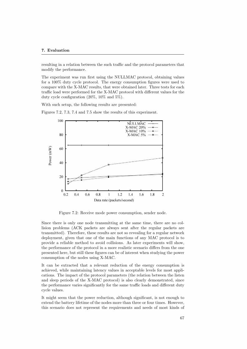
7. Evaluation
resulting in a relation between the such traffic and the protocol parameters thatmodify the performance.
The experiment was run first using the NULLMAC protocol, obtaining valuesfor a 100% duty cycle protocol. The energy consumption figures were used tocompare with the X-MAC results, that were obtained later. Three tests for eachtraffic load were performed for the X-MAC protocol with different values for theduty cycle configuration (20%, 10% and 5%).
With such setup, the following results are presented:
Figures 7.2, 7.3, 7.4 and 7.5 show the results of this experiment.
Figure 7.2: Receive mode power consumption, sender node.
Since there is only one node transmitting at the same time, there are no col-lision problems (ACK packets are always sent after the regular packets aretransmitted). Therefore, these results are not so revealing for a regular networkdeployment, given that one of the main functions of any MAC protocol is toprovide a reliable method to avoid collisions. As later experiments will show,the performance of the protocol in a more realistic scenario differs from the onepresented here, but still these figures can be of interest when studying the powerconsumption of the nodes using X-MAC.
It can be extracted that a relevant reduction of the energy consumption isachieved, while maintaining latency values in acceptable levels for most appli-cations. The impact of the protocol parameters (the relation between the listenand sleep periods of the X-MAC protocol) is also clearly demonstrated, sincethe performance varies significantly for the same traffic loads and different dutycycle values.
It might seem that the power reduction, although significant, is not enough toextend the battery lifetime of the nodes more than three or four times. However,this scenario does not represent the requirements and needs of most kinds of
67

7.2. Scenario 1: Single-hop Energy Consumption
Figure 7.3: Receive mode power consumption, sink node.
Figure 7.4: Transmit mode power consumption, send node.
68

7. Evaluation
Figure 7.5: Round trip time.
WSN, or at least the ones that this thesis focuses on. The X-MAC implemen-tation obtains better results for scenarios in which the expected traffic load ismuch lower than in this case.
Generally, increasing the traffic rate increases the receive energy for any node.As was described earlier, the transmission procedure requires that strobes ofpreamble packets are sent before the actual packet is transmitted. The sendernode must, after sending each of these preamble packets, turn the radio on inorder to detect a special preamble packet acknowledgment signaling that thereceiver has detected the sender transmission and that it is ready to receive thepacket. The receive mode energy consumption is therefore very sensitive to theload of the network, since a lot of traffic implies that this procedure is carriedout more often.
For example, for the lowest traffic load tested in this case, a 5% duty cyclepresents the best result of the three options, saving almost a 80% of the NULL-MAC implementation behaviour with the same traffic load. Having such a con-figuration means that the node spends listening only 20ms out of every 400ms.If transmissions occur very seldom, like in that case, it seems reasonable to havesuch a low cycle value. However, the worst obtained results corresponds to thesame configuration dealing with a traffic load eight times larger (2 packets persecond). Having a very long sleep period in a duty cycle system can decreasethe performance because of the longer preamble send/receive sequence that isrequired to reach the receiver. If the network deals with a low traffic load, this iscompensated by the energy save caused by having the radio off for a long time.If traffic increases, the energy consumption is obviously affected. The RTT isalso affected by the duty cycle scheme but not by the traffic load. Since thereare no collision problems, the transmission mechanism should take the sametime on average under the same cycle conditions.
69
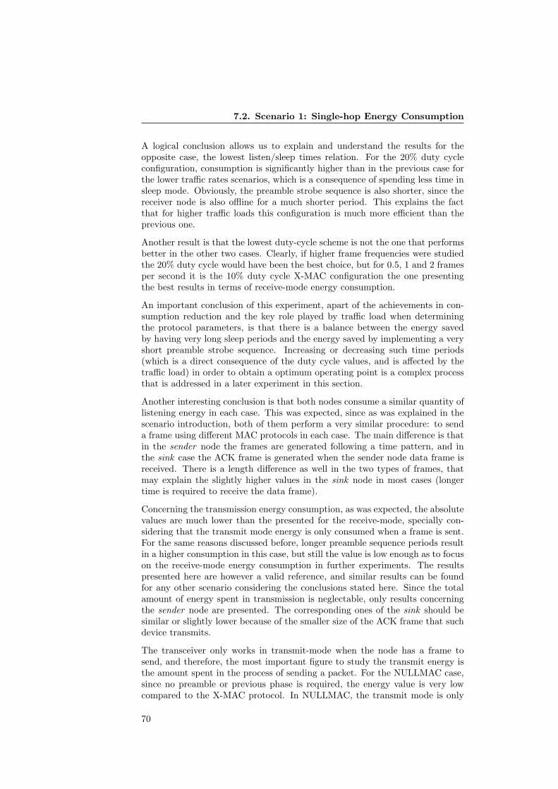
7.2. Scenario 1: Single-hop Energy Consumption
A logical conclusion allows us to explain and understand the results for theopposite case, the lowest listen/sleep times relation. For the 20% duty cycleconfiguration, consumption is significantly higher than in the previous case forthe lower traffic rates scenarios, which is a consequence of spending less time insleep mode. Obviously, the preamble strobe sequence is also shorter, since thereceiver node is also offline for a much shorter period. This explains the factthat for higher traffic loads this configuration is much more efficient than theprevious one.
Another result is that the lowest duty-cycle scheme is not the one that performsbetter in the other two cases. Clearly, if higher frame frequencies were studiedthe 20% duty cycle would have been the best choice, but for 0.5, 1 and 2 framesper second it is the 10% duty cycle X-MAC configuration the one presentingthe best results in terms of receive-mode energy consumption.
An important conclusion of this experiment, apart of the achievements in con-sumption reduction and the key role played by traffic load when determiningthe protocol parameters, is that there is a balance between the energy savedby having very long sleep periods and the energy saved by implementing a veryshort preamble strobe sequence. Increasing or decreasing such time periods(which is a direct consequence of the duty cycle values, and is affected by thetraffic load) in order to obtain a optimum operating point is a complex processthat is addressed in a later experiment in this section.
Another interesting conclusion is that both nodes consume a similar quantity oflistening energy in each case. This was expected, since as was explained in thescenario introduction, both of them perform a very similar procedure: to senda frame using different MAC protocols in each case. The main difference is thatin the sender node the frames are generated following a time pattern, and inthe sink case the ACK frame is generated when the sender node data frame isreceived. There is a length difference as well in the two types of frames, thatmay explain the slightly higher values in the sink node in most cases (longertime is required to receive the data frame).
Concerning the transmission energy consumption, as was expected, the absolutevalues are much lower than the presented for the receive-mode, specially con-sidering that the transmit mode energy is only consumed when a frame is sent.For the same reasons discussed before, longer preamble sequence periods resultin a higher consumption in this case, but still the value is low enough as to focuson the receive-mode energy consumption in further experiments. The resultspresented here are however a valid reference, and similar results can be foundfor any other scenario considering the conclusions stated here. Since the totalamount of energy spent in transmission is neglectable, only results concerningthe sender node are presented. The corresponding ones of the sink should besimilar or slightly lower because of the smaller size of the ACK frame that suchdevice transmits.
The transceiver only works in transmit-mode when the node has a frame tosend, and therefore, the most important figure to study the transmit energy isthe amount spent in the process of sending a packet. For the NULLMAC case,since no preamble or previous phase is required, the energy value is very lowcompared to the X-MAC protocol. In NULLMAC, the transmit mode is only
70

7. Evaluation
activated for the short period that it takes for the radio to transmit the 128bytes frame. On the other hand, X-MAC requires to send a preamble sequencebefore sending the final packet, so the transmit energy in that case includes thepreamble phase transmission and the data frame transmission.
7.3 Scenario 2: Single-hop with Contention
In the first scenario, the power saving capabilities of the X-MAC protocol weredemonstrated. The previous scenario only tests the capacity of 2 nodes, andtherefore no collisions contention problems are found. However, in most net-work topologies, it is usual that more than one node is operating withing range.MAC protocols must deal with contention avoidance mechanisms, and the per-formance of the whole system can be severely affected if there is too much trafficin the area and collisions are not properly dealt with.
For this experiment, 3 nodes are used in a similar way that in the previous case.2 of the nodes run the same program as the sending node in the Experiment1 (sender1 and sender2 ). These nodes send packets to a third node (sink).The main parameters and elements are basically the same as before, with theaddition of a third node that competes for the channel with the original sender.Figure 7.6 depicts the scenario.
The goal of this second experiment is to check if the X-MAC implementationused in the previous scenario is suitable to work in a situation in which morethan one node try to transmit with other transmitting nodes present in theircommunication range. It is expected that the power-saving capacity of theprevious test is affected because of the collisions caused by many nodes tryingto access the channel.
According to Buettner et al [10], if the channel is busy at the moment of startinga new transmission, the node must be aware of that, since the device thatis actually using the medium must have sent the preamble sequence at thebeginning of its transmission. If such preamble has been detected by the nodetrying to start a new communication, a flag variable indicating that other nodeis using the channel prevents the communication to start until a sleep period ofthe duty cycle expires. As a consequence, in networks dealing with a lot of trafficthe latency of the system is expected to be higher and to be traffic-dependent.
For this experiment, packets have again the same format as in the previous case.Frames consist of a 100 bytes length payload and a header formed by addressesin long format and the other control fields. The total length is, as before, 128bytes.
Once again, traffic load is a crucial parameter that clearly determines the per-formance of the protocol. In this case, higher values mean not only that thenode has to deal with many transmissions trying to save as much energy aspossible, but also they must be prepared to do so in the presence of packets notdestined for them while assuring a reliable communication with the sink node.In this case, the X-MAC is configured to have a duty-cycle scheme with a 10%of the time spent in listening mode, since this was the setting that provided theoverall better results in most cases of the previous experiment.
71

7.3. Scenario 2: Single-hop with Contention
Figure 7.6: Scenario 2 scheme
The same measurements as in the previous scenario were performed, and theparameters are also the same. Only one duty cycle configuration is used thistime. Figures 7.7, 7.8, 7.9 and 7.10
Ideally, if there were not contention problems in the channel, the numericalresults of this experiment would be almost the same as in the first scenario.However, it can be extracted from the results that as a consequence of the nodessharing the same channel in scenarios with relatively high traffic load the perfor-mance of individual nodes is affected in both latency and energy consumptionresults.
In the case in which both sender nodes transmit 2 packets per second, a to-tal of 4 packets per seconds are transmitted in the channel. If these packetswere equally distributed, 250ms would be required as the maximum RTT valueto avoid collision problems. Even in this ideal situation, and considering theRTT values obtained in the previous experiment, this time seems to be tooshort to avoid collisions problems in the channel. The packets generation isnot distributed, worsening the situation. This explains the very high number ofcollisions that nodes have to deal with in this case, which clearly increase theRTT. It is important to remind that if the channel is busy at the moment ofthe transmission, the node must wait for a complete cycle before being allowed
72
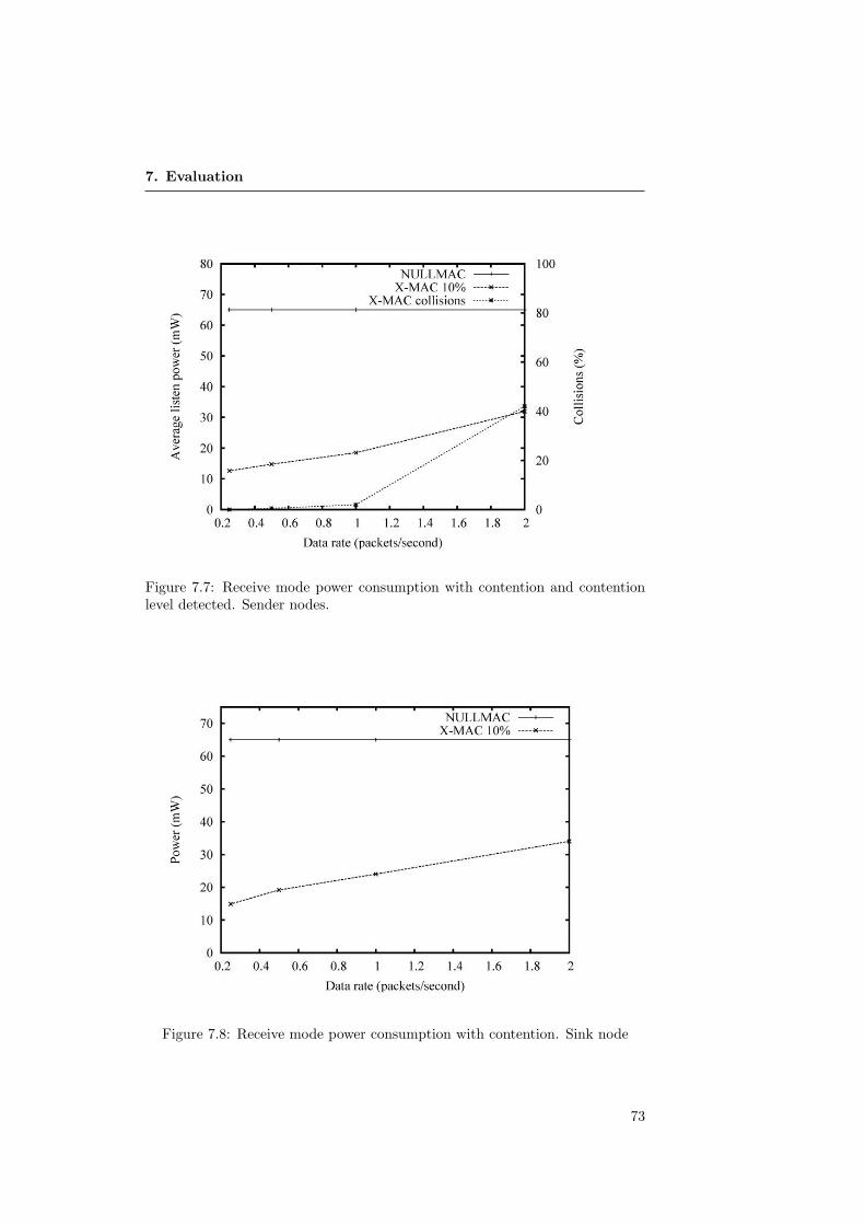
7. Evaluation
Figure 7.7: Receive mode power consumption with contention and contentionlevel detected. Sender nodes.
Figure 7.8: Receive mode power consumption with contention. Sink node
73

7.3. Scenario 2: Single-hop with Contention
Figure 7.9: Transmit mode power consumption with contention.
Figure 7.10: Round trip time with contention.
74

7. Evaluation
to attempt to transmit again. This feature of the X-MAC protocol results in anadditional average delay of 200 ms for the 10% duty cycle configuration used ifa collision is detected. The result obtained for latency in this case is consistantwith the previous one, since it is is close to adding that delay to the single nodelatency in a 42% of the cases.
The receive-mode energy result is also worse in this case than in the single-node scenario. The explanation lies in the fact that generally, when more trafficis present in the area, strobe sequences are longer since the destination nodenormally enters in a sleep period after having finished dealing with other trans-missions. Additionally, even during the node own strobe period it is possiblethat it receives a preamble packet from another node that has not detected thesender node own preamble sequence and has started its own, which results inthe sender node having to start again its preamble sequence once the channelis free again.
All these effects of a very busy channel are not so relevant in the cases wheretraffic conditions do not provoke such a high number of collisions like the pre-vious case. For instance, when each node sends 1 packet per second only a 2%of these were affected by collisions, and for a transmission schedule of 1 packetevery 2 second only a 0.5% are affected. As can be extracted for the results,in those cases the Receive-mode energy is slightly lower comparing the valueswith the appropriate ones from the previous experiment for the sender nodes.Assuming that the nodes are not affected anymore by collisions when the trafficload decreases (or at least not as much as in the earlier case), the explanationlies in the fact that each node still detects eventual preamble sequences thatare not destinated for the listening node. In that case, and according to the X-MAC specification, the listen period is immediately halted and the node turnsits radio off, resulting in the shortening of the listen period of the duty cycle,so in overall the nodes spend less time with the radio on.
The absence of collision problems also means that RTT-latency results are notgreatly affected in the cases with less traffic present, being similar to the onespresented for the previous experiment.
In the first scenario, both the sender and the sink node performed very similaroperations. Given that an ACK frame was required for every data frame trans-mitted by the sender, both of them had to deal with almost the same traffic inthe same conditions. In this case however, the sink node must process twice thetraffic of the individual sender nodes, since an ACK frame is required for eachframe generated in each of the senders. Having to deal with much more trafficcompared to the equivalent previous situations or to the other nodes included inthis scenario explains the worse results that the sink node presents in this case.For every traffic load the sink node consumes more energy in the receive-modethan the other nodes or the sink itself in the Experiment 1. Actually, consider-ing that the traffic load the sink deals with is twice the traffic generated in eachnode, comparing results of Experiments 1 and 2 provides very similar values,since the ‘1 packet per second’ in Experiment 2 is equivalent to ‘2 packets persecond’ in Experiment 1 and so on.
Another conclusion that can be extracted is that a high traffic load in this casealso affects in the transmit-mode energy spent per packet. Longer preamble
75
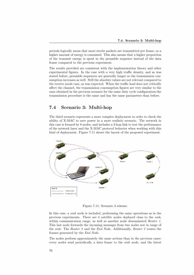
7.4. Scenario 3: Multi-hop
periods logically mean that more strobe packets are transmitted per frame, so ahigher amount of energy is consumed. This also means that a higher proportionof the transmit energy is spent in the preamble sequence instead of the dataframe compared to the previous experiment.
The results provided are consistent with the implementation theory and otherexperimental figures. In the case with a very high traffic density, and as wasstated before, preamble sequences are generally longer so the transmission con-sumption increases as well. Still the absolute values are not relevant compared tothe receive mode case, as was expected. When the traffic load does not criticallyaffect the channel, the transmission consumption figures are very similar to theones obtained in the previous scenario for the same duty cycle configuration-thetransmission procedure is the same and has the same parameters than before.
7.4 Scenario 3: Multi-hop
The third scenario represents a more complex deployment in order to check theability of X-MAC to save power in a more realistic scenario. The network inthis case is formed by 8 nodes, and includes a 3-hop link to test the performanceof the network layer and the X-MAC protocol behavior when working with thiskind of deployment. Figure 7.11 shows the layout of the proposed experiment.
Figure 7.11: Scenario 3 scheme.
In this case, a sink node is included, performing the same operations as in theprevious experiments. There are 4 satellite nodes deployed close to the sink,within communication range, as well as another node denominated Router 1.This last node forwards the incoming messages from two nodes not in range ofthe sink : The Router 2 and the End Node. Additionally, Router 2 routes theframes generated by the End Node.
The nodes perform approximately the same actions than in the previous cases:every nodes send periodically a data frame to the sink node, and the latest
76
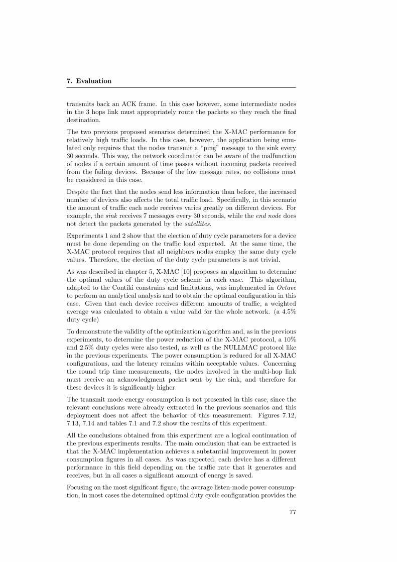
7. Evaluation
transmits back an ACK frame. In this case however, some intermediate nodesin the 3 hops link must appropriately route the packets so they reach the finaldestination.
The two previous proposed scenarios determined the X-MAC performance forrelatively high traffic loads. In this case, however, the application being emu-lated only requires that the nodes transmit a “ping” message to the sink every30 seconds. This way, the network coordinator can be aware of the malfunctionof nodes if a certain amount of time passes without incoming packets receivedfrom the failing devices. Because of the low message rates, no collisions mustbe considered in this case.
Despite the fact that the nodes send less information than before, the increasednumber of devices also affects the total traffic load. Specifically, in this scenariothe amount of traffic each node receives varies greatly on different devices. Forexample, the sink receives 7 messages every 30 seconds, while the end node doesnot detect the packets generated by the satellites.
Experiments 1 and 2 show that the election of duty cycle parameters for a devicemust be done depending on the traffic load expected. At the same time, theX-MAC protocol requires that all neighbors nodes employ the same duty cyclevalues. Therefore, the election of the duty cycle parameters is not trivial.
As was described in chapter 5, X-MAC [10] proposes an algorithm to determinethe optimal values of the duty cycle scheme in each case. This algorithm,adapted to the Contiki constrains and limitations, was implemented in Octaveto perform an analytical analysis and to obtain the optimal configuration in thiscase. Given that each device receives different amounts of traffic, a weightedaverage was calculated to obtain a value valid for the whole network. (a 4.5%duty cycle)
To demonstrate the validity of the optimization algorithm and, as in the previousexperiments, to determine the power reduction of the X-MAC protocol, a 10%and 2.5% duty cycles were also tested, as well as the NULLMAC protocol likein the previous experiments. The power consumption is reduced for all X-MACconfigurations, and the latency remains within acceptable values. Concerningthe round trip time measurements, the nodes involved in the multi-hop linkmust receive an acknowledgment packet sent by the sink, and therefore forthese devices it is significantly higher.
The transmit mode energy consumption is not presented in this case, since therelevant conclusions were already extracted in the previous scenarios and thisdeployment does not affect the behavior of this measurement. Figures 7.12,7.13, 7.14 and tables 7.1 and 7.2 show the results of this experiment.
All the conclusions obtained from this experiment are a logical continuation ofthe previous experiments results. The main conclusion that can be extracted isthat the X-MAC implementation achieves a substantial improvement in powerconsumption figures in all cases. As was expected, each device has a differentperformance in this field depending on the traffic rate that it generates andreceives, but in all cases a significant amount of energy is saved.
Focusing on the most significant figure, the average listen-mode power consump-tion, in most cases the determined optimal duty cycle configuration provides the
77

7.4. Scenario 3: Multi-hop
Figure 7.12: Receive mode power consumption in multihop scenario.
Figure 7.13: Receive mode power consumption in multihop scenario. Compari-sion of X-MAC configurations.
78
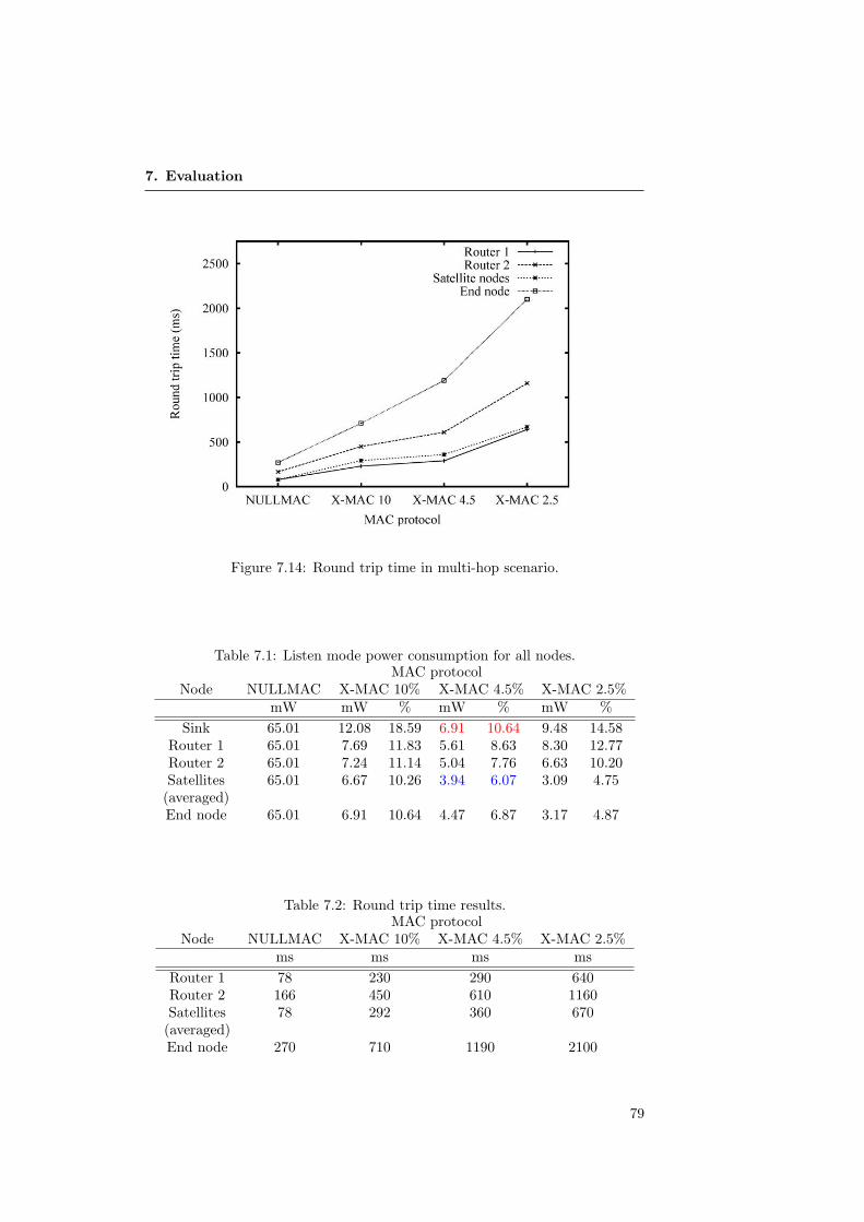
7. Evaluation
Figure 7.14: Round trip time in multi-hop scenario.
Table 7.1: Listen mode power consumption for all nodes.MAC protocol
Node NULLMAC X-MAC 10% X-MAC 4.5% X-MAC 2.5%mW mW % mW % mW %
Sink 65.01 12.08 18.59 6.91 10.64 9.48 14.58Router 1 65.01 7.69 11.83 5.61 8.63 8.30 12.77Router 2 65.01 7.24 11.14 5.04 7.76 6.63 10.20Satellites 65.01 6.67 10.26 3.94 6.07 3.09 4.75
(averaged)End node 65.01 6.91 10.64 4.47 6.87 3.17 4.87
Table 7.2: Round trip time results.MAC protocol
Node NULLMAC X-MAC 10% X-MAC 4.5% X-MAC 2.5%ms ms ms ms
Router 1 78 230 290 640Router 2 166 450 610 1160Satellites 78 292 360 670
(averaged)End node 270 710 1190 2100
79

7.4. Scenario 3: Multi-hop
best results. This demonstrates the validity of the model implemented. How-ever, given that the mathematical expressions of the model are built using thetraffic load as the main variable, for some devices the averaged traffic load calcu-lated differs significantly of their actual situation and other configurations savemore energy (like the satellite nodes and the end node, that save more energy ifa 2.5% duty cycle is used). One practical conclusion obtained from that obser-vation is that having a homogeneous network topology makes the optimizationestimations converge to the real solution. An alternative solution would consistof modifying the X-MAC protocol so that it can work with different duty cyclesfor different devices in the network.
The optimal duty cycle configuration presents its better result for the satellitenodes (a save of a 93.3% or 61.07 mW), and the higher consumption for thesink (a save of 89.3% or 58.1 mW). When considering the global consumptionof the network, the node consuming more energy is a limiting factor, speciallyif such node performs critical tasks, like in this case. Therefore, the main resultthat can be extracted is that the optimized X-MAC configuration can extendthe the battery lifetime of the whole network by almost ten times.
An important result of the previous scenarios is that the listen consumptionincreases with traffic. In this case, Router 1 and Router 2 are acting as routersbecause they have to forward messages from other nodes to the sink. Thesetwo devices as well as the sink present a higher power consumption because ofthe increased amount of traffic that they send and receive. With the optimalduty cycle configuration, around a 90% of energy is saved compared to theNULLMAC implementation, which is an excellent result.
It is also observed that the end node and the satellite nodes, which do not actas routers, present lower consumptions. Among these, the end node presentsa slightly higher consumption in all cases. The explanation lies in the factthat satellite nodes were located close to the sink. According to the X-MACprotocol, when they detect a preamble sequence targeted to the sink, they turntheir radio off immediately to save energy until the detected transmission iscompleted. Given that all the traffic of the network has the sink node as thefinal destination, these satellite nodes detect a lot of traffic not destined forthem so the described procedure occurs very often, which explains the lowerconsumption compared to the end node.
It can also be observed that those nodes transmitting using a multi-hop linkrequire longer times to make their information reach the final destination andreceiving the ACK packet back as was expected. This effect can suppose asignificant impact for those devices located far away from the sink, since for someduty cycle configurations the round trip time can be of more than 1 second inthe optimal case. However, considering that this parameter measures a two-waycommunication, the proposed configurations maintain an acceptable responsetime even for node 90 which is 3 hops away from the sink.
For the transmit mode energy, no relevant information is extracted in this case.Transmissions occur very seldom in this case, so the energy consumed in thetransmission procedure can be again neglected when considering the total powerconsumption of the platform.
Summarizing, the X-MAC implementation proposed is a suitable solution for
80

7. Evaluation
scenarios with low traffic rates and multi hop links. Thanks to the optimizationmechanism included the consumption results are even better, but still a methodto determine the average traffic load of the network is required.
81

7.4. Scenario 3: Multi-hop
82
Reducing the Energy Consumption of ZigBee with a Power-savingMAC Protocol8. Conclusions and Future Work
Chapter 8
Conclusions and FutureWork
Wireless sensor networks have a wide range of possibilities. A number of ap-plications can benefit from the low cost and versatility of tiny sensor nodes.As was described in chapter 2, each of these applications have specific require-ments that must be considered when designing the network characteristics andparameters.
To reach an optimal solution not only in terms of power consumption, but also inmost other performance parameters, a crucial first step consists of choosing theright equipment and network architecture for the specific application required.A significant effort must be made in the early design stages to determine whichof the available options are the most suitable in each case.
The use of an already developed standard provides a number of advantages toboth the developer and the final user. ZigBee is an excellent choice for mostWSN potential applications, but it must be combined with a MAC protocolto achieve acceptable low power consumption characteristics when the beaconbased operation mode is not available.
The developed version of X-MAC has proved to be a suitable option for thiskind of scenario. As the experiments performed show, power consumption issignificantly reduced in all cases while the rest of network parameters maintainacceptable values. Specifically, the X-MAC performance results in the multi-hopscenario, with consumption values obtained between a 95% and a 90% below theregular ZigBee implementation are an excelent demostration of the possibilitiesof this protocol.
The election of an appropriate duty cycle scheme depends on the traffic loadthat the network must process. The use of an optimization application provideanalytically obtained parameters that have been proved to be the best ones.The modification of the X-MAC implementation to allow an adaptive recon-figuration of the duty cycle parameters depending on the traffic load detectedwould improve the protocol versatility and the general performance in most
83
applications, specially those that must deal with sudden changes in the traffictriggered by, for example, an alarm event.
Furthermore, the design of the network also has an impact in the power con-sumption reduction. If an homogeneous topology is deployed, the optimizationalgorithm provides more accurate results, since the traffic load would be equallydistributed through the network. Another possibility that should be consideredis to perform the optimization estimation taking the traffic expected in the sinknode as the input parameter, since it is generally the device receiving the trafficof all the nodes, consuming more power and becoming a critical element of thenetwork.
Another relevant experiment result is the existing trade-off between latency andenergy consumption in duty cycles schemes. This is an expected consequence ofimplementing longer sleep periods in order to save energy. Since the nodes spendlonger times with the radio turned off to save energy, communication cannot beperformed immediately. This must be considered during the design phase of thenetwork in order to meet the requirements of the specific applications in termsof response time.
Buettner et al [10] propose a minimum listen period of 20msecs, based on thelimitations imposed by the TinyOS implementation of X-MAC that they devel-oped. The optimization application actually presents better values for shorterlistening periods, but they have been discarded such configurations are not sup-ported. If that limit can be lowered new possible duty cycle configurationswould be available, achieving the same connectivity while significantly reducingthe power consumption. The NES group at SICS is currently working in thispossibility.
The application of mathematical and statistical tools to describe and predictnetwork behavior is clearly a great advantage that provides designers and de-velopers the possibility of designing products with very specific constraints orrequirements, and to predict the behavior in critical situations. Further researchshould be conducted in this field considering a network scope instead of focusingon the single devices behavior.
Apart from the development of MAC protocols, extending the battery lifetimeshould be studied as the combination of different solutions at different levels toobtain an integral system adapted to the requirements and characteristics of aspecific scenario should be considered. The combination of a suitable MAC pro-tocol with hardware specifically designed to recharge batteries obtaining energyfrom the medium [25] can also be considered and in some conditions provide analmost permanent status for a WSN. Other proposals [27] have demonstratedthat it is possible to save significant amounts of power by implementing smartrouting techniques that consider the consumption of each node in the network.
The recent addition of the ENERGEST module to Contiki 2.1. allows thenodes forming a WSN to be aware of how much power are they consuming.Further improvement in the batteries models could allow the nodes to knowhow much battery life they have left. Apart from the advantages that theaccess to this information provide to the application and users of the network,this could be used to optimize the routing protocols. If a node periodicallybroadcasts information about its battery state to its neighbors, the routing
84
8. Conclusions and Future Work
table may be modified to contain this information as well, and in the cases wheremore then one route is available, the nodes would be able to choose the one thattransmits the information to the node with more battery remaining. This waythe power depletion in the network would be evenly distributed, extending thetotal lifetime.
Summarizing, the combination of X-MAC and other MAC protocols with com-munications stack such as ZigBee can extend the battery lifetime of nodes form-ing a WSN, as demonstrated in the experimental results presented in this report.This enables the use of WSNs for a number of applications. Still, further de-velopment is required in the field of MAC protocols (specifically in the X-MACimplementation) as well as in other possible solutions to achieve an integralsolution that extends the battery lifetime of the nodes as to be considered asemi-permanent solution.
85

86
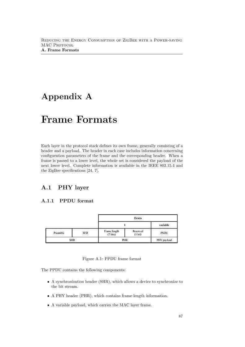
Reducing the Energy Consumption of ZigBee with a Power-savingMAC ProtocolA. Frame Formats
Appendix A
Frame Formats
Each layer in the protocol stack defines its own frame, generally consisting of aheader and a payload. The header in each case includes information concerningconfiguration parameters of the frame and the corresponding header. When aframe is passed to a lower level, the whole set is considered the payload of thenext lower level. Complete information is available in the IEEE 802.15.4 andthe ZigBee specifications [24, 7].
A.1 PHY layer
A.1.1 PPDU format
Figure A.1: PPDU frame format
The PPDU contains the following components:
• A synchronization header (SHR), which allows a device to synchronize tothe bit stream.
• A PHY header (PHR), which contains frame length information.
• A variable payload, which carries the MAC layer frame.
87

A.2. MAC layer
A.2 MAC layer
A.2.1 General MAC frame format
Figure A.2: General MAC frame format
The following fields are included in the MAC general frame:
• Frame control field.
Figure A.3: Frame control field
The frame control field is 2 bytes long and includes information definingthe frame type, addressing fields and other control flags.
• Sequence Number field.The sequence Number field is 1 byte length and specifies the sequenceidentifier for the frame. The sequence number of the next frame to besent is stored in the MAC PIB and is increased every time a frame isgenerated.
• Destination PAN Identifier field.The Destination PAN Identifier is an optional field, and is 2 bytes inlength. It specifies the unique PAN identifier of the intended recipient ofthe frame. A value of 0xffff represents the broadcast PAN identifier.
• Destination Address field.The Destination Address is an optional field that can be 2 or 8 byteslength. It specifies the address of the intended recipient of the frame. A16-bit value of 0xffff specifies the broadcast short address
• Source PAN Identifier field.The Source PAN Identifier is an optional field, 2 bytes long. When presentit specifies the PAN Identifier of the originator of the frame.
88

A. Frame Formats
• Source Address field.The Source Address is an optional field that can be 2 or 8 bytes length.It specifies the address of the originator of the frame.
• Auxiliary Security field.The Auxiliary Security Header optional field has a variable length andspecifies information required for security processing. It specifies the typeof security applied to the frame.
• Frame Payload field.The Frame payload field has a variable length and contains informationspecific to the different frame types.
• FCS field.The FCS field consists of a checksum code used to verify the integrity ofthe received frame.
A.2.2 Beacon frame format
The beacon frame format is illustrated in figure A.4.
Figure A.4: Beacon frame format
The payload in this case is formed by four information fields: a GTS fieldand a pending information field, used to implement the beacon functionalitiesdescribed in Chapter 3, a Superframe Specification that determines the config-uration of the superframe scheme used. and a Beacon Payload. These fields arespecified in Figures A.5, A.6 and A.7.
Figure A.5: Format of the GTS information field
89

A.2. MAC layer
Figure A.6: Format of pending address field
Figure A.7: Format of the beacon specification field
A.2.3 ACK frame format
The ACK frame format is illustrated in figure A.8.
Figure A.8: Format of the ACK frame.
A.2.4 MAC command frames
The MAC command frame general format is illustrated in figure A.9.
The command field includes information related with the specific task that theframe performs. More information is available in [24].
90
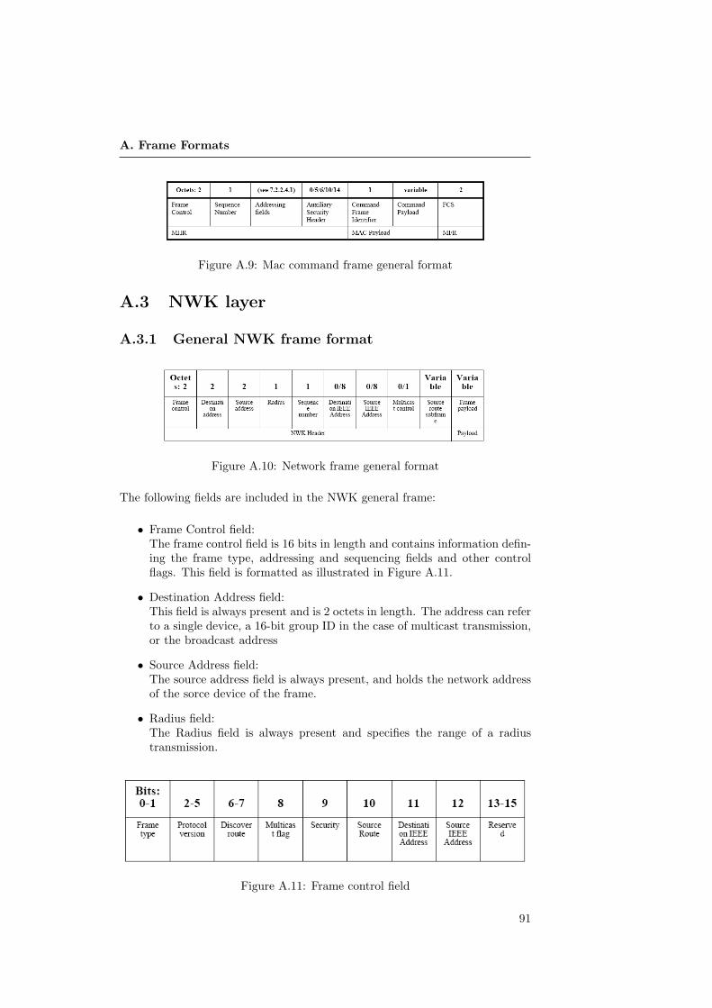
A. Frame Formats
Figure A.9: Mac command frame general format
A.3 NWK layer
A.3.1 General NWK frame format
Figure A.10: Network frame general format
The following fields are included in the NWK general frame:
• Frame Control field:The frame control field is 16 bits in length and contains information defin-ing the frame type, addressing and sequencing fields and other controlflags. This field is formatted as illustrated in Figure A.11.
• Destination Address field:This field is always present and is 2 octets in length. The address can referto a single device, a 16-bit group ID in the case of multicast transmission,or the broadcast address
• Source Address field:The source address field is always present, and holds the network addressof the sorce device of the frame.
• Radius field:The Radius field is always present and specifies the range of a radiustransmission.
Figure A.11: Frame control field
91
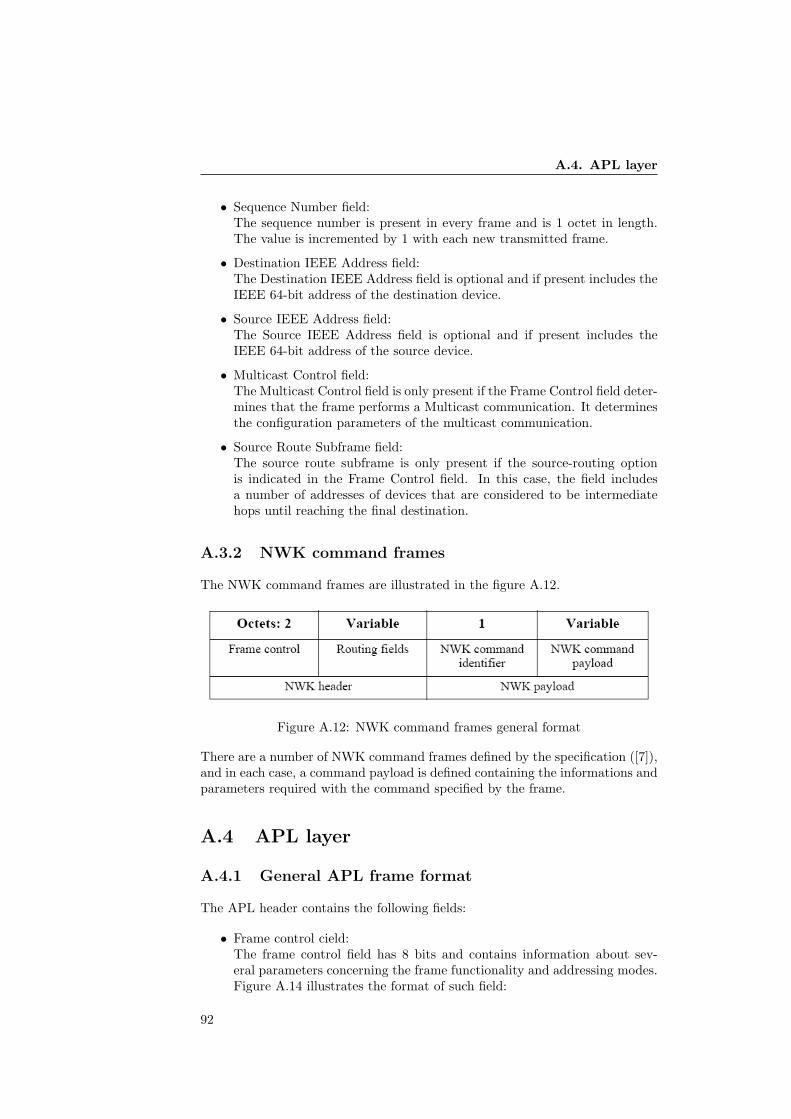
A.4. APL layer
• Sequence Number field:The sequence number is present in every frame and is 1 octet in length.The value is incremented by 1 with each new transmitted frame.
• Destination IEEE Address field:The Destination IEEE Address field is optional and if present includes theIEEE 64-bit address of the destination device.
• Source IEEE Address field:The Source IEEE Address field is optional and if present includes theIEEE 64-bit address of the source device.
• Multicast Control field:The Multicast Control field is only present if the Frame Control field deter-mines that the frame performs a Multicast communication. It determinesthe configuration parameters of the multicast communication.
• Source Route Subframe field:The source route subframe is only present if the source-routing optionis indicated in the Frame Control field. In this case, the field includesa number of addresses of devices that are considered to be intermediatehops until reaching the final destination.
A.3.2 NWK command frames
The NWK command frames are illustrated in the figure A.12.
Figure A.12: NWK command frames general format
There are a number of NWK command frames defined by the specification ([7]),and in each case, a command payload is defined containing the informations andparameters required with the command specified by the frame.
A.4 APL layer
A.4.1 General APL frame format
The APL header contains the following fields:
• Frame control cield:The frame control field has 8 bits and contains information about sev-eral parameters concerning the frame functionality and addressing modes.Figure A.14 illustrates the format of such field:
92
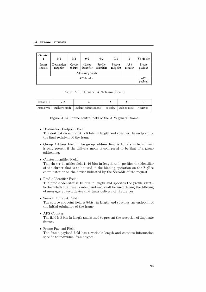
A. Frame Formats
Figure A.13: General APL frame format
Figure A.14: Frame control field of the APS general frame
• Destination Endpoint Field:The destination endpoint is 8 bits in length and specifies the endpoint ofthe final recipient of the frame.
• Group Address Field: The group address field is 16 bits in length andis only present if the delivery mode is configured to be that of a groupaddressing.
• Cluster Identifier Field:The cluster identifier field is 16-bits in length and specifies the identifierof the cluster that is to be used in the binding operation on the ZigBeecoordinator or on the device indicated by the SrcAddr of the request.
• Profile Identifier Field:The profile identifier is 16 bits in length and specifies the profile identi-fierfor which the frme is intendend and shall be used during the filteringof messages at each device that takes delivery of the frames.
• Source Endpoint Field:The source endpoint field is 8-bist in length and specifies tne endpoint ofthe initial originator of the frame.
• APS Counter:The field is 8 bits in length and is used to prevent the reception of duplicateframes.
• Frame Payload Field:The frame payload field has a variable length and contains informationspecific to individual frame types.
93

A.4. APL layer
94
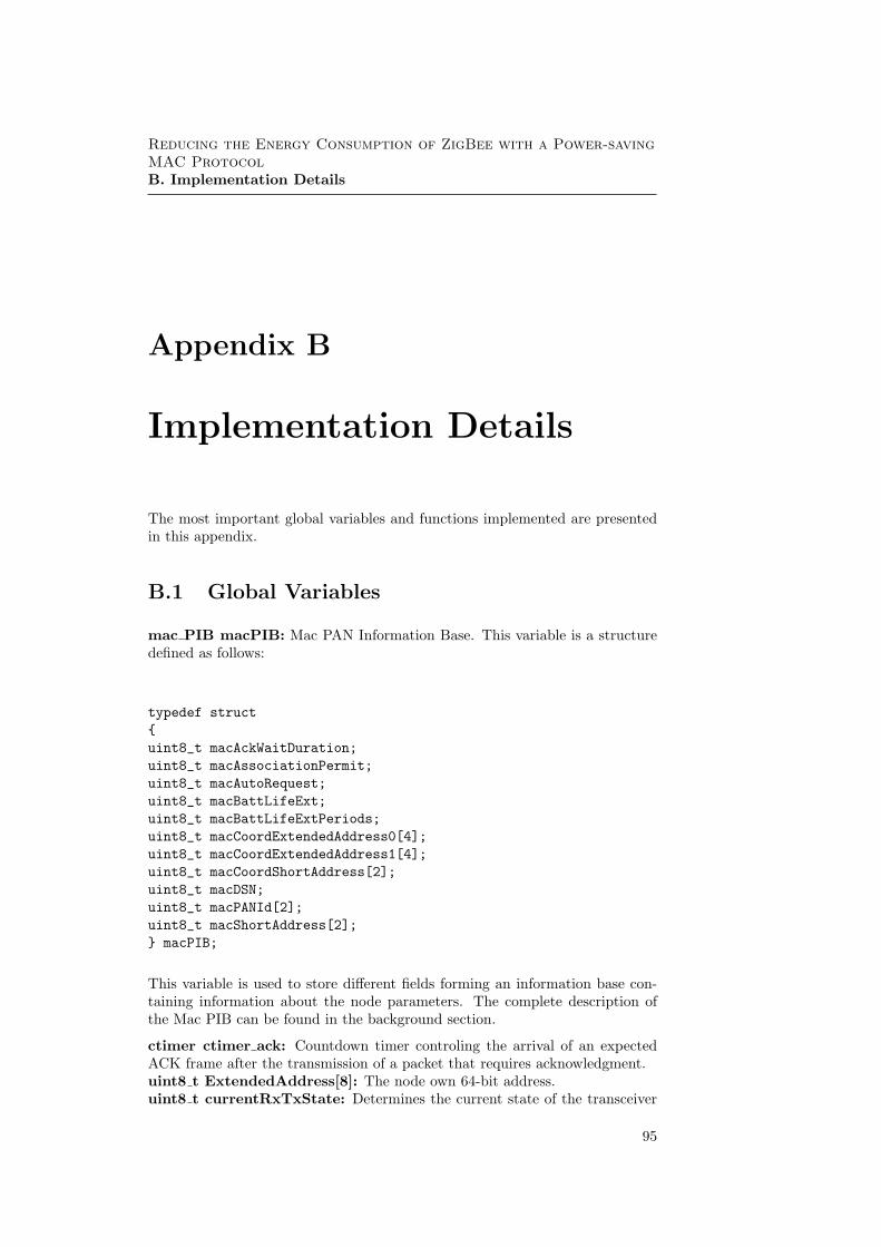
Reducing the Energy Consumption of ZigBee with a Power-savingMAC ProtocolB. Implementation Details
Appendix B
Implementation Details
The most important global variables and functions implemented are presentedin this appendix.
B.1 Global Variables
mac PIB macPIB: Mac PAN Information Base. This variable is a structuredefined as follows:
typedef struct{uint8_t macAckWaitDuration;uint8_t macAssociationPermit;uint8_t macAutoRequest;uint8_t macBattLifeExt;uint8_t macBattLifeExtPeriods;uint8_t macCoordExtendedAddress0[4];uint8_t macCoordExtendedAddress1[4];uint8_t macCoordShortAddress[2];uint8_t macDSN;uint8_t macPANId[2];uint8_t macShortAddress[2];} macPIB;
This variable is used to store different fields forming an information base con-taining information about the node parameters. The complete description ofthe Mac PIB can be found in the background section.
ctimer ctimer ack: Countdown timer controling the arrival of an expectedACK frame after the transmission of a packet that requires acknowledgment.uint8 t ExtendedAddress[8]: The node own 64-bit address.uint8 t currentRxTxState: Determines the current state of the transceiver
95

B.1. Global Variables
(RX ON,TX ON or TRX OFF).uint8 t CapabilityInformation: Contains information about the device type,the power source or security capabilites of the node.indirect transmission element indirect trans queue[INDIRECT BUFFER SIZE]:Indirect transmission buffer used to store the mesages that are going to be trans-mitted upon the request of the destination device. The indirect transmission elementstructure type is defined as follows:
typedef struct{uint8_t handler;uint16_t transaction_persistent_time;uint8_t hdr_length;uint8_t payload\_length;uint8_t header[28];uint8_t payload[127];}indirect_transmission_element;
More information on indirect transmissions can be found in the background sec-tion.
uint8 t indirect trans count: Total number of messages in the indirect trans-mission buffer.uint8 t receive buffer[]: Receive buffer where the bits sequence conformingan incoming frame is stored.uint8 t send buffer[]: Send buffer where the bits sequence conforming anoutgoing frame are stored before being transmitted.phyPIB phy PIB: Used to store the physical layer PAN Information Base.The phyPIB structure is defined as:
typedef struct{uint8_t phyCurrentChannel;uint8_t phyChannelsSupported;uint8_t phyTransmitPower;} phyPIB;
routing table element routing table[MAX ROUTING ELEMENTS]:Maintains information about routes to different devices. The routing table ele-ment is defined as follows:
typedef struct routing_table_element{ \uint8_t DstAddr[2];uint8_t NextHop[2];uint8_t RouteControl;}routing_table_element;
96

B. Implementation Details
neighbortableentry neighbortable[MAX NEIGHBOR ELEMENTS]:Maintains information about the neighboring devices. The routing table elementis defined as follows:
typedef struct{uint16_t PAN\_Id;uint32_t Extended\_Address0;uint32_t Extended\_Address1;uint16_t Network\_Address;uint8_t Device\_Type;uint8_t Relationship;uint8_t LQI;uint8_t Logical_Channel;} neighbortableentry;
routing discovery element discovery table[MAX ROUTING ELEMENTS];Maintains information about the routes being discovered. The route discoveryelement is defined as follows:
typedef struct route_discovery_element{uint8_t RouteRequestID;uint8_t SourceAddress[2];uint8_t SenderAddress[2];}route_discovery_element;
B.2 Functions Implemented
void route discovery unicast(uint8 t DstAddr[2],uint8 t Radius):This function initiates the discovery process, by setting the routing table androute discovery table parameters and broadcasting a discovery frame. A timeris set to expire after a timeout period.
void route frame(uint8 t DstAddr[2],uint8 t Radius):This function is called when a frame with a NWK address not matching thedevice is received. The node searches in its routing table for an entry with theappropriate destination address, and if it is found, copies the frame payload toa new generated frame that is transmitted to the next-hop address present inthe table entry.
void process incoming mpdu(int len):This function is called after the reception of a frame in the MAC layer. Theextracts header fields from the bits sequence stored in the buffer. Such valuesare stored in variables defined as different structures depending on the frameformat that is being processed. When the operation is completed the next higher
97
B.2. Functions Implemented
layer is notified, and the MAC payload is stored in a different buffer availableat the higher layer. See Figure ()
void create mpdu(MAC HDR send hdr,uint8 t msdu[],uint8 t msdu len):This function is called by the network layer when it requests to create a MACframe. It receives the header fields in the send hdr variable, the MAC payload inthe msdu buffer argument, and its lenght as a separate parameter. The functioncreates a MAC frame with the format specified by the header fields parameters,and stores it in the send buffer so that it is made available to be sent after beingrequested to the MAC protocol. Alternatively, a create cmd frame function ex-ists that performs the same operation but creating different types of commandframes that are later transmitted following the same procedure.
MPDU HDR XX get mac header xx(void):A number of ‘get mac header xx´ functions have been written. The xx mustbe replaced of l,s or n, standing for Long, short or non-present address typesfor the sender and receiver nodes. These functions are called from the pro-cess incoming mpdu function, and they access the read buffer byte by byte inorder to extract information for the different fields. The format of the framestored in the buffer is already known when calling this function, since this isdetermined by the address types of the frame that were previously extractedin the process incoming mpdu function. A number of variable structures havebeen defined to store the header fields, with the appropiate addressess fields ineach case.
void build ack(uint8 t sequence,uint8 t frame pending):This function creates an ACK frame and stores it in the send buffer. Thearguments are the sequence number and the frame pending bit, fields of theACK frame header.
simple cc2420 send(const u8 t *payload, u16 t payload len):The send function is called when the frame to be sent has been formed in theMAC layer and is stored in the adequate buffer. A pointer to that buffer and itslength are the arguments received by this function. The function automaticallyperforms a CCA operation, performing a reduced version of the CSMA/CAmechanism before the packet is put in the transmission FIFO buffer.
u16 t cc2420 read(u8 t *buf, u16 t bufsize):The read function receives as arguments the buffer where to store the readinformation from the cc2420 FIFO buffer, as well as its maximum size. Thefunction returns the number of bytes read and stored in the buffer, not includingthe preamble and footer sequences. The function also performs an automaticcheck of the redundancy code included in such sequences.
98
Reducing the Energy Consumption of ZigBee with a Power-savingMAC ProtocolBIBLIOGRAPHY
Bibliography
[1] Bluetooth Special Interest Group. http://www.bluetooth.org/. 3
[2] IEEE 802.15 Work Group. http://www.ieee802.org/15/. 3
[3] The ZigBee Alliance web site. http://www.zigbee.org. 11
[4] Msp430 Datasheet. Texas Instruments, 1999. 36
[5] CC2420 Datasheet. Chipcon AS, 2004. 36
[6] Tmote Sky Datasheet. Moteiv Co. Ltd, 2006. 29
[7] ZigBee Specification 2006. ZigBee Alliance, Dec. 2006. 11, 87, 92
[8] Abrach, H., Bhatti, S., Carlson, J., Dai, H., Rose, J., Sheth,A., Shucker, B., Deng, J., and Han, R. Mantis: system support formultimdal networks of in-situ sensors. In Proc. WSNA’03 (Nov. 2003). 29
[9] Boulis, A., Han, C., and Srivastava, M. B. Design and implemen-tation of a framework for efficient and programmable sensor networks. InProc. MOBISYS’03 (May 2003). 29
[10] Buettner, M., Yee, G., Anderson, E., and Han, R. X-MAC: Ashort preamble mac protocol for duty-cycledwireless networks. Tech. rep.,University of Colorado at Boulder, 2006. IX, 41, 44, 45, 71, 77, 84
[11] Callaway, E. Wireless sensor networks : architectures and protocols.Auerbach Publications, 2004. 4, 5, 8
[12] Cunha, A., Alves, M., and Koubaa, A. An IEEE 802.15.4 protocolimplementation(in nesc/tinyos): Reference Guide v1.2. Tech. rep., IPP-HURRAY, Instituto Politecnico do Porto, 2007. 47
[13] Dam, T. v., and Langendoen, K. An adaptive energy-efficient MACprotocol for wireless sensor networks. In SenSys03 (Los Angeles, CA, nov2003), pp. 171–180. 42
[14] Demirkol, I., Ersoy, C., and Alagoz, F. Mac protocols for wirelesssensor networks: a survey. IEEE Communications Magazine (2006). 40
[15] Dunkels, A. The uip embedded tcp/ip stack. the uip 1.0 reference manual.Tech. rep., Swedish Institute of Computer Science, 2006. 35
99
BIBLIOGRAPHY
[16] Dunkels, A. Contiki 2.1. Reference Manual, 2007. 32
[17] Dunkels, A. Rime — a lightweight layered communication stack for sensornetworks. In Proceedings of the European Conference on Wireless SensorNetworks (EWSN), Poster/Demo session (Delft, The Netherlands, Jan.2007). IX, 34, 35
[18] Dunkels, A., Gronvall, B., and Voigt, T. Contiki - a lightweightand flexible operating system for tiny networked sensors. In Proceedingsof the First IEEE Workshop on Embedded Networked Sensors (Emnets-I)(Tampa, Florida, USA, Nov. 2004). 29
[19] Dunkels, A., Schmidt, O., Voigt, T., and Ali, M. Protothreads:Simplifying event-driven programming of memory-constrained embeddedsystems. In Proceedings of the Fourth ACM Conference on EmbeddedNetworked Sensor Systems (SenSys 2006) (Boulder, Colorado, USA, Nov.2006). 32
[20] Dunkels, A., Osterlind, F., Tsiftes, N., and He, Z. Software-basedon-line energy estimation for sensor nodes. In Proceedings of the FourthWorkshop on Embedded Networked Sensors (Emnets IV) (Cork, Ireland,June 2007). 62, 63
[21] El-Hoiydi, A., and Decotignie, J.-D. WiseMAC: An ultra low powerMAC protocol for multi-hop wireless sensor networks. In First Int. Work-shop on Algorithmic Aspects of Wireless Sensor Networks (ALGOSEN-SORS 2004), Lecture Notes in Computer Science, LNCS 3121 (July 2004),Springer-Verlag, pp. 18–31. 42
[22] Garcia-Hernandez, C., Ibarguengoytia-Gonzalez, P., Garcıa-Hernandez, J., and Perez-Dıaz, J. Wireless sensor networks and ap-plications: a survey. IJCSNS International Journal of Computer Scienceand Network Security, VOL.7 No.3. (2007). 3
[23] Hill, J. L. System Architecture for Wireless Sensor Networks. PhD thesis,University of California, Berkeley, 2003. 3, 4, 5, 8
[24] IEEE 802.15 Working Group for WPAN. IEEE Standard for Infor-mation technology Telecommunications and information exchange betweensystems Local and metropolitan area networks Specific requirements Part15.4: Wireless Medium Access Control (MAC) and Physical Layer (PHY)Specifications for Low-Rate Wireless Personal Area Networks (WPANs),2006. IX, 11, 13, 14, 16, 17, 19, 50, 55, 87, 90
[25] Jeong, J., Jiang, X. F., and Culler, D. E. Design and analysis ofmicro-solar power systems for wireless sensor networks. Tech. rep., Electri-cal Engineering and Computer Sciences. University of California at Berke-ley, 2007. 46, 84
[26] Levis, P. Tinyos 2.0 overview. Tech. rep., Computer Systems Laboratory,Stanford University, 2006. 29
100
BIBLIOGRAPHY
[27] Li, Q., Aslam, J. A., and Rus, D. Online power-aware routing inwireless ad-hoc networks. In Mobile Computing and Networking (2001),pp. 97–107. 46, 84
[28] Polastre, J., Hill, J., and Culler, D. Versatile low power mediaaccess for wireless sensor networks. In SenSys04 (Baltimore, MD, Nov.2004), pp. 95–107. 43
[29] Prasad, R., and Munoz, L. WLANS and WPANs towards 4G wireless.Artech House Publishers, 1993. 3
[30] Raghnathan, V., Schurgers, C., Park, S., and Srivastrava, M. B.Energy-aware wireless microsensor networks. IEEE Signal Processing Mag-azine (March 2002). 5, 9, 39
[31] Rajendran, V., Obraczka, K., and Garcia-Luna-Aceves, J.Energy-efficient, collision-free medium access control for wireless sensornetworks. Wireless Networks 12, 1 (2006), 63–78. 43
[32] Reynolds, J. C. The discoveries of continuations. LISP and SymbolicComputation 6, 3–4 (1993), 233–247. 33
[33] Rhee, I., Warrier, A., Aia, M., and Min, J. Z-MAC: a hybrid MACfor wireless sensor networks. In SenSys05 (San Diego, CA, 2005), pp. 90–101. 44
[34] Romer, K., and Mattern, F. The design space of wireless sensor net-works. IEEE Wireless Communications Magazine (2004). 4
[35] von Behren, R., Condit, J., and Brewer, E. Why events are a badidea (for high-concurrency servers). In HOTOS’03: Proceedings of the 9thconference on Hot Topics in Operating Systems (Berkeley, CA, USA, 2003),USENIX Association, pp. 4–4. 31
[36] Warneke, B., Last, M., Liebowitz, B., and Pister, K. S. Smartdust: Communicating with a cubic-millimeter computer. Computer, vol 34(2001). 4
[37] Wheeler, A. Avoiding rf interference between wifi and zigbee. Tech. rep.,The ZigBee Alliance, 2006. 63
[38] Ye, W., Heidemann, J., and Estrin, D. An energy-efficient MAC pro-tocol for wireless sensor networks. In 21st Conference of the IEEE Com-puter and Communications Societies (INFOCOM) (2002), vol. 3, pp. 1567–1576. 41
[39] Zurita, B. Adaptive source and channel coding algorithms for energysaving in wireless sensor networks. Master’s thesis, Kungliga TekniskaHogskolan, Stockholm, 2006. 46
101