reducing the time to market for new bmc applications part design and rapid prototyping for bmc
TRANSCRIPT
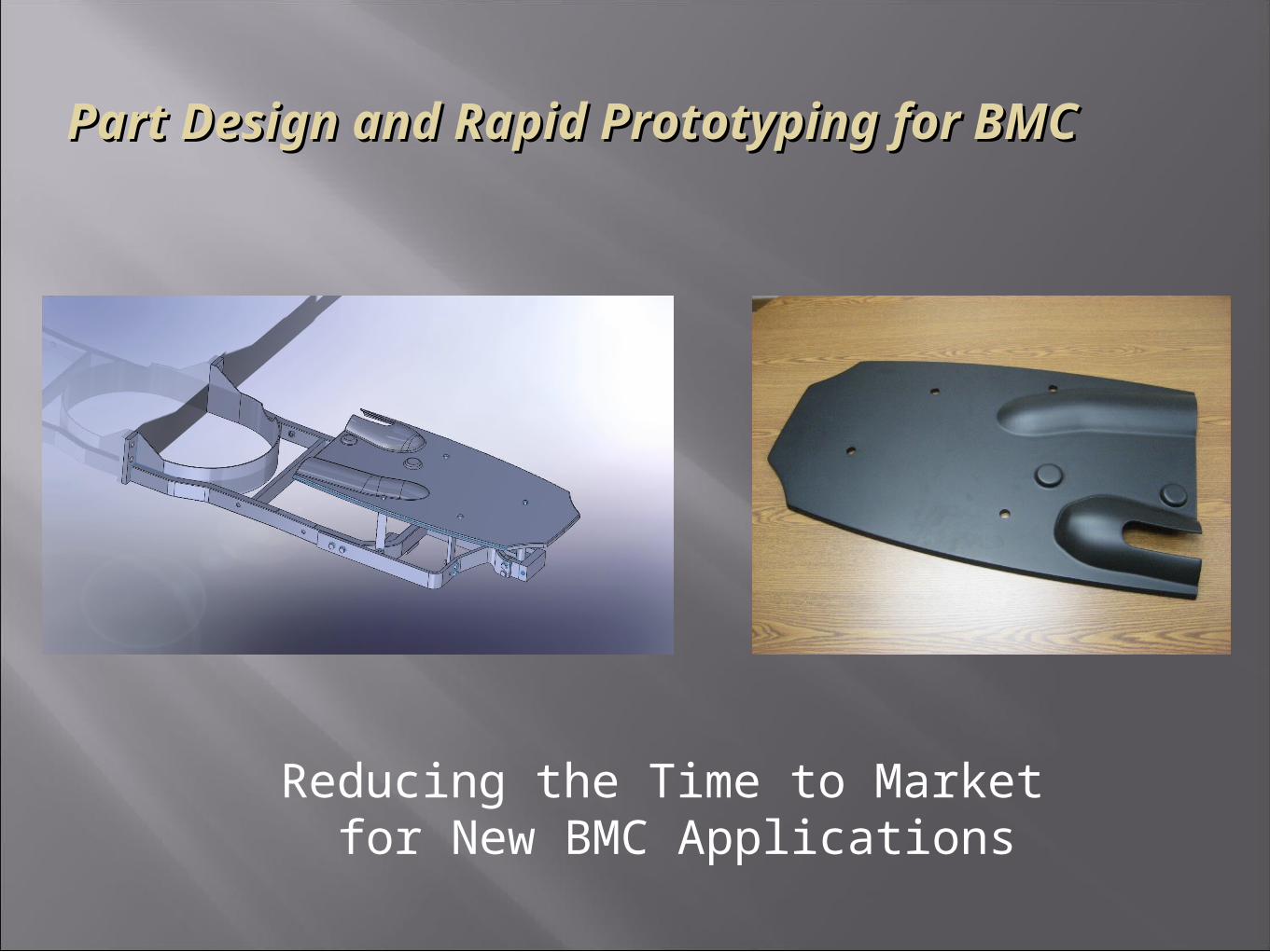
Reducing the Time to Market for New BMC Applications
Part Design and Rapid Prototyping for Part Design and Rapid Prototyping for BMCBMC
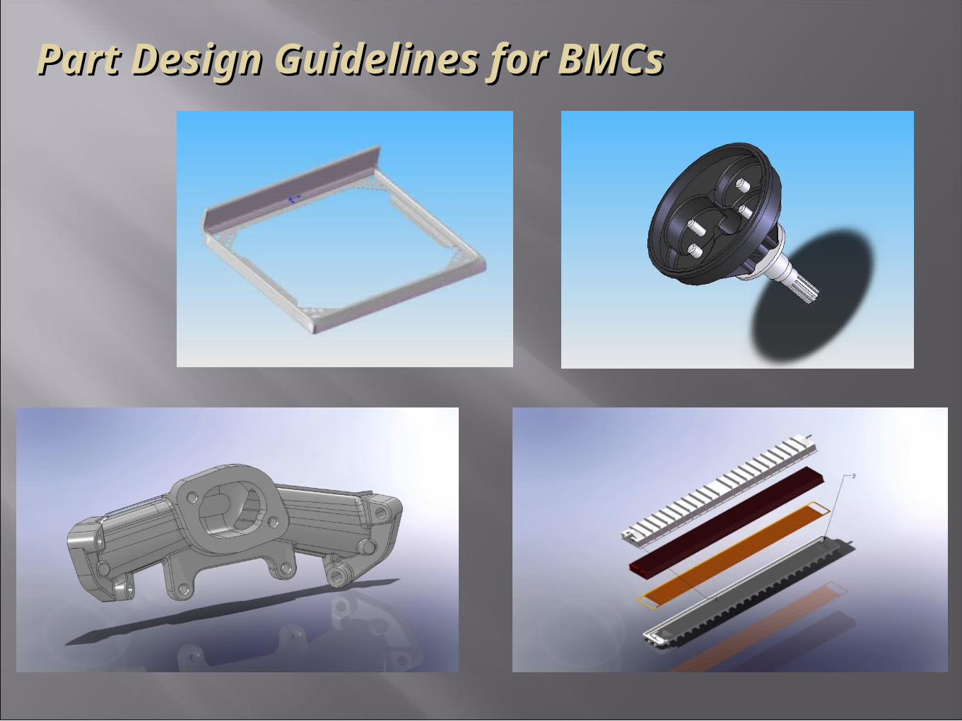
Part Design Guidelines for BMCsPart Design Guidelines for BMCs
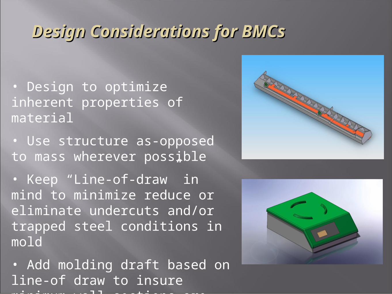
Design Considerations for BMCsDesign Considerations for BMCs
• Design to optimize inherent properties of material
• Use structure as-opposed to mass wherever possible
• Keep “Line-of-draw” in mind to minimize reduce or eliminate undercuts and/or trapped steel conditions in mold
• Add molding draft based on line-of draw to insure minimum wall sections are maintained
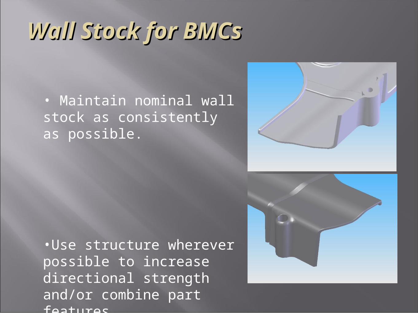
Wall Stock for BMCsWall Stock for BMCs
• Maintain nominal wall stock as consistently as possible.
•Use structure wherever possible to increase directional strength and/or combine part features
Wall Stock for BMCsWall Stock for BMCs
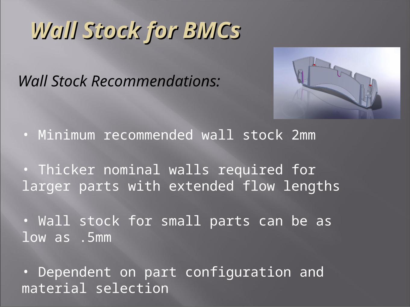
Wall Stock Recommendations:
• Minimum recommended wall stock 2mm
• Thicker nominal walls required for larger parts with extended flow lengths
• Wall stock for small parts can be as low as .5mm
• Dependent on part configuration and material selection
Wall Stock for BMCsWall Stock for BMCs
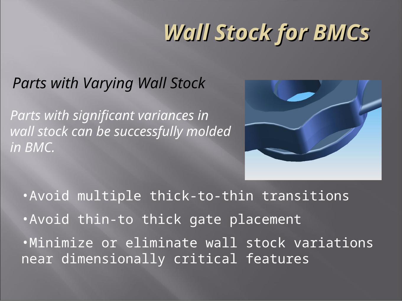
Parts with Varying Wall Stock
Parts with significant variances inwall stock can be successfully moldedin BMC.
•Avoid multiple thick-to-thin transitions
•Avoid thin-to thick gate placement
•Minimize or eliminate wall stock variations near dimensionally critical features
Molding DraftMolding Draft
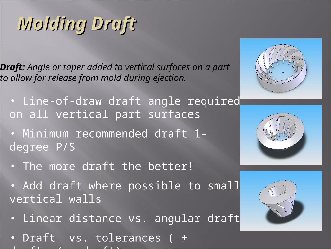
• Line-of-draw draft angle required on all vertical part surfaces
• Minimum recommended draft 1-degree P/S
• The more draft the better!
• Add draft where possible to small vertical walls
• Linear distance vs. angular draft
• Draft vs. tolerances ( + draft / - draft)
Draft: Angle or taper added to vertical surfaces on a partto allow for release from mold during ejection.
Molding DraftMolding Draft
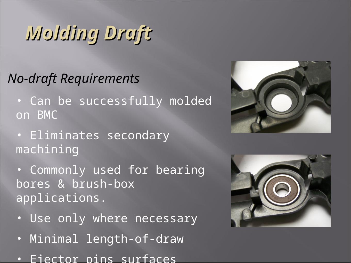
No-draft Requirements
• Can be successfully molded on BMC
• Eliminates secondary machining
• Commonly used for bearing bores & brush-box applications.
• Use only where necessary
• Minimal length-of-draw
• Ejector pins surfaces adjacent to feature
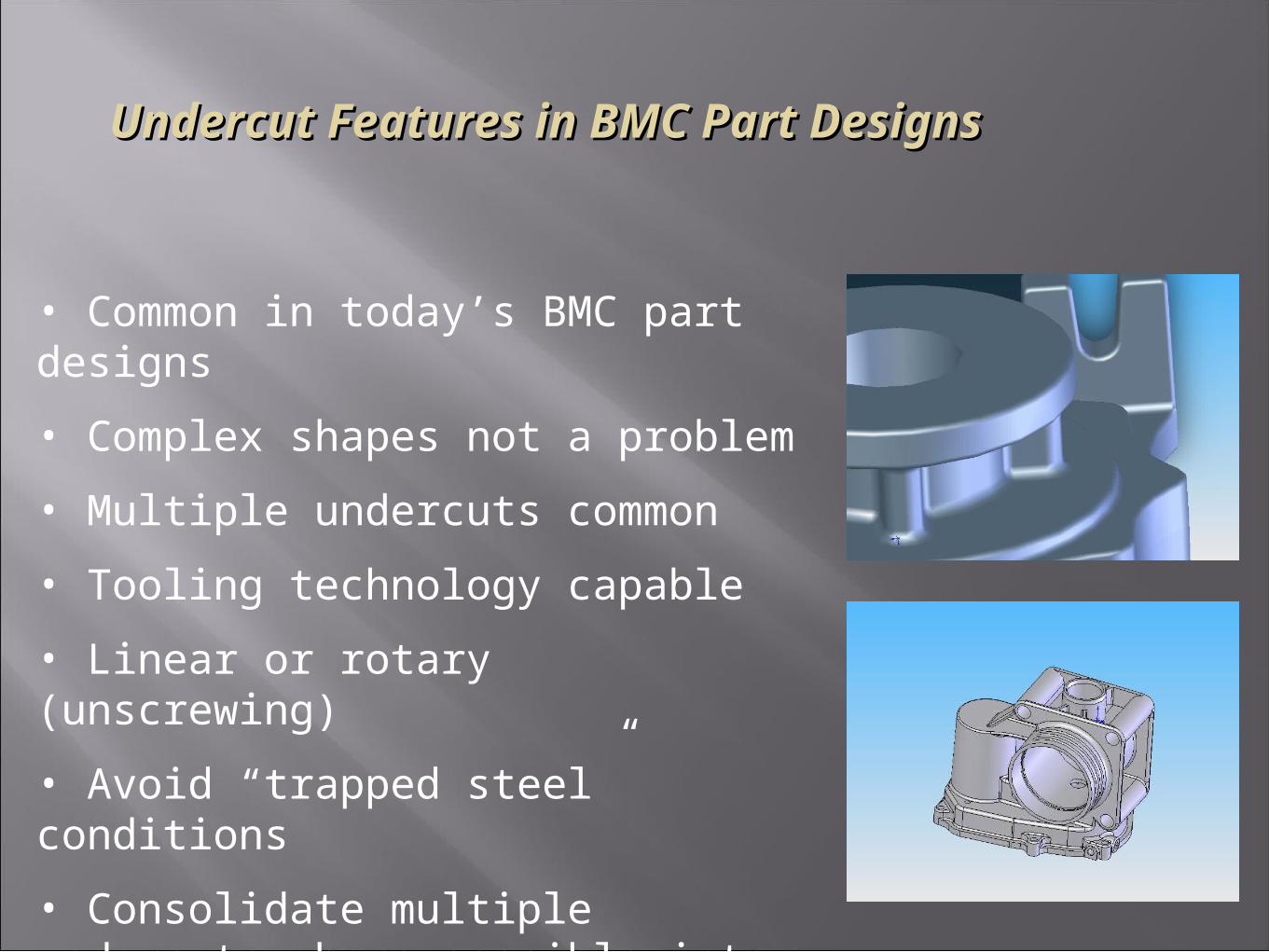
Undercut Features in BMC Part DesignsUndercut Features in BMC Part Designs
• Common in today’s BMC part designs
• Complex shapes not a problem
• Multiple undercuts common
• Tooling technology capable
• Linear or rotary (unscrewing)
• Avoid “trapped steel” conditions
• Consolidate multiple undercuts where possible into same line-of-draw
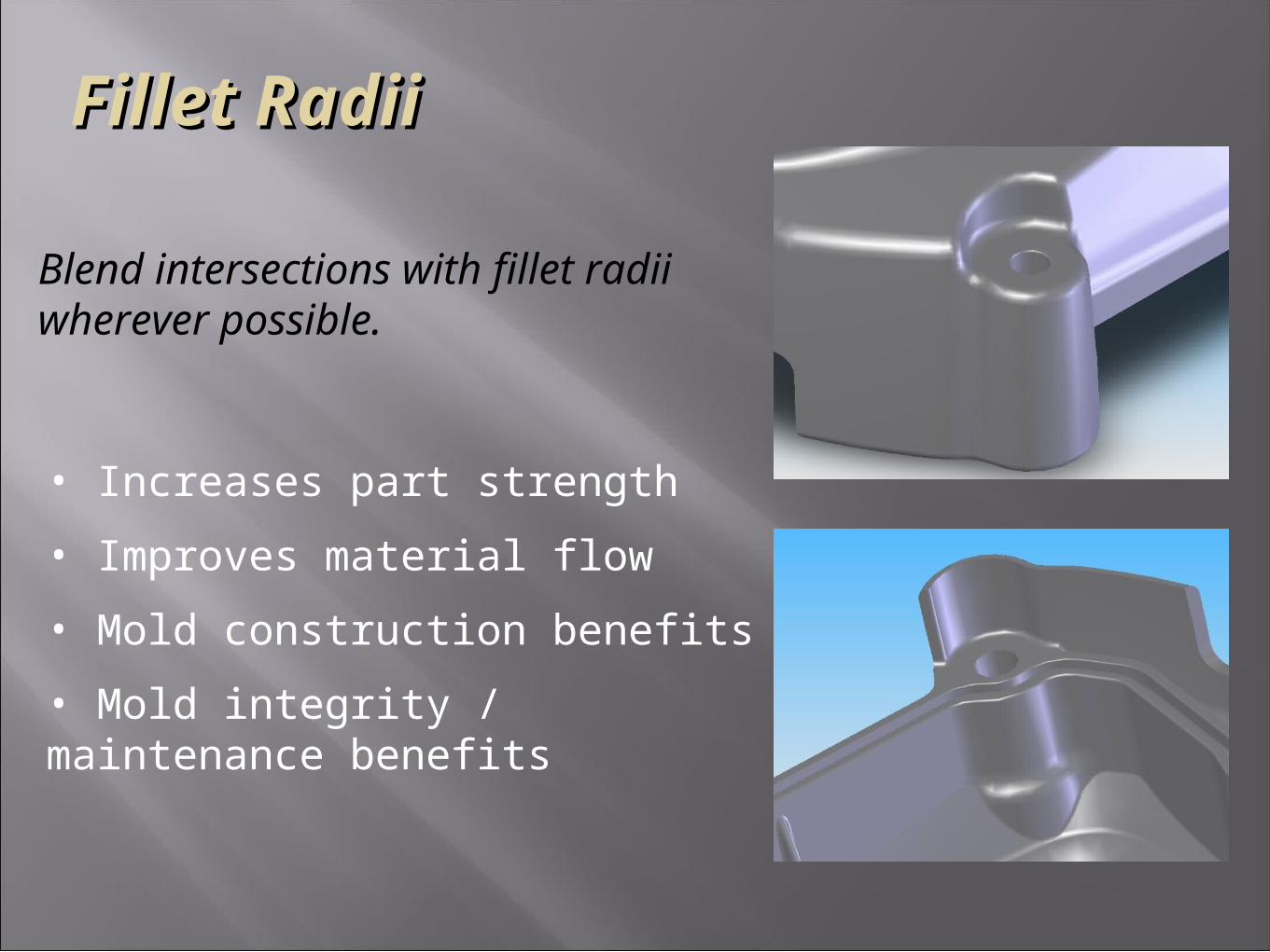
Fillet RadiiFillet Radii
Blend intersections with fillet radii wherever possible.
• Increases part strength
• Improves material flow
• Mold construction benefits
• Mold integrity / maintenance benefits
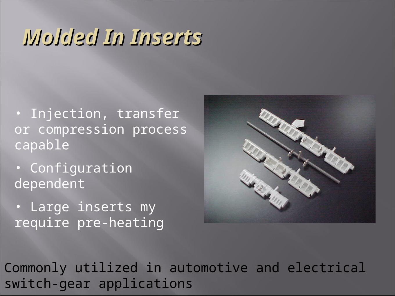
Molded In InsertsMolded In Inserts
• Injection, transfer or compression process capable
• Configuration dependent
• Large inserts my require pre-heating
Commonly utilized in automotive and electrical switch-gear applications
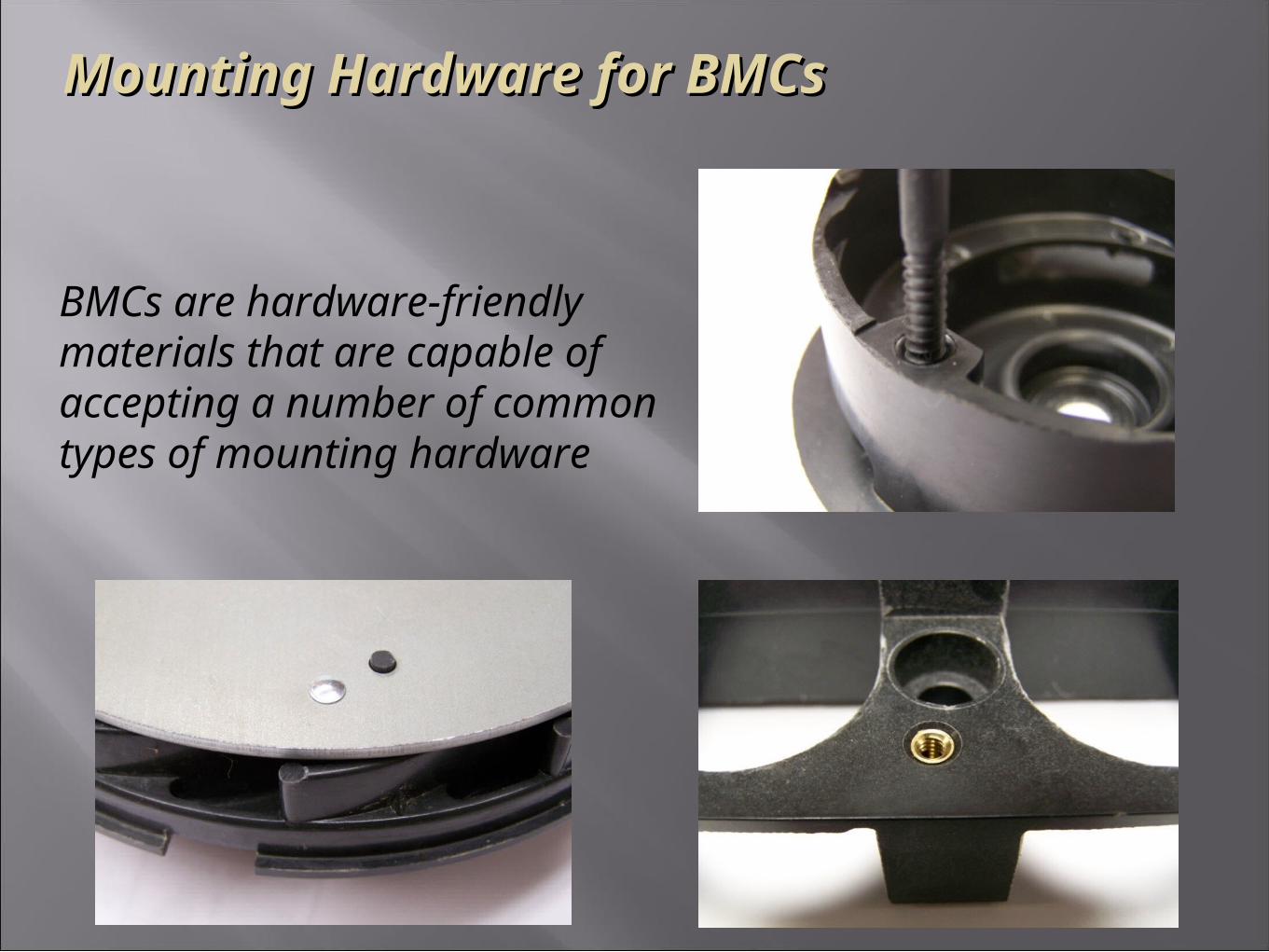
Mounting Hardware for BMCsMounting Hardware for BMCs
BMCs are hardware-friendly materials that are capable of accepting a number of common types of mounting hardware
Mounting Hardware for BMCsMounting Hardware for BMCs
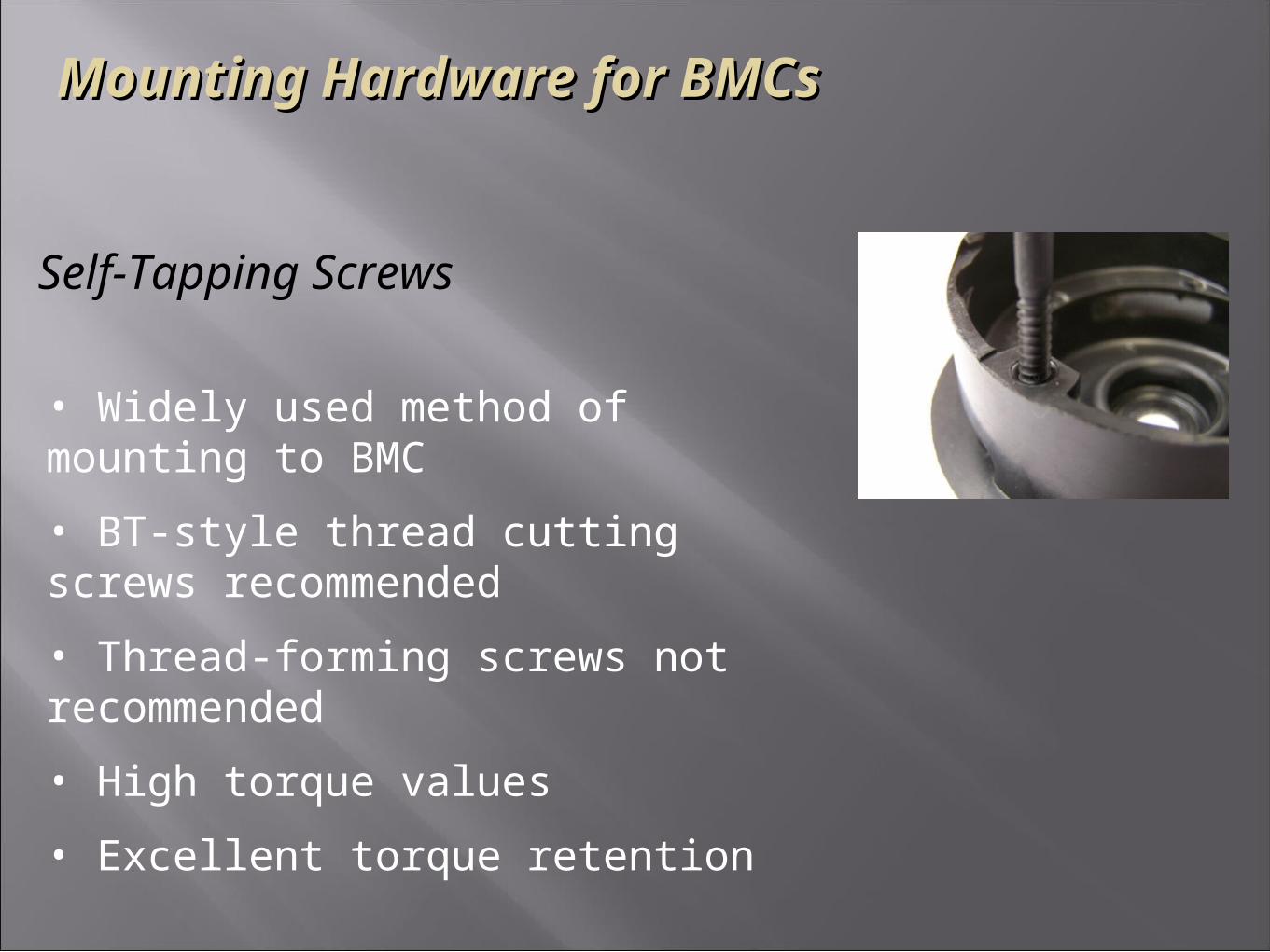
Self-Tapping Screws
• Widely used method of mounting to BMC
• BT-style thread cutting screws recommended
• Thread-forming screws not recommended
• High torque values
• Excellent torque retention
Mounting Hardware for BMCsMounting Hardware for BMCs
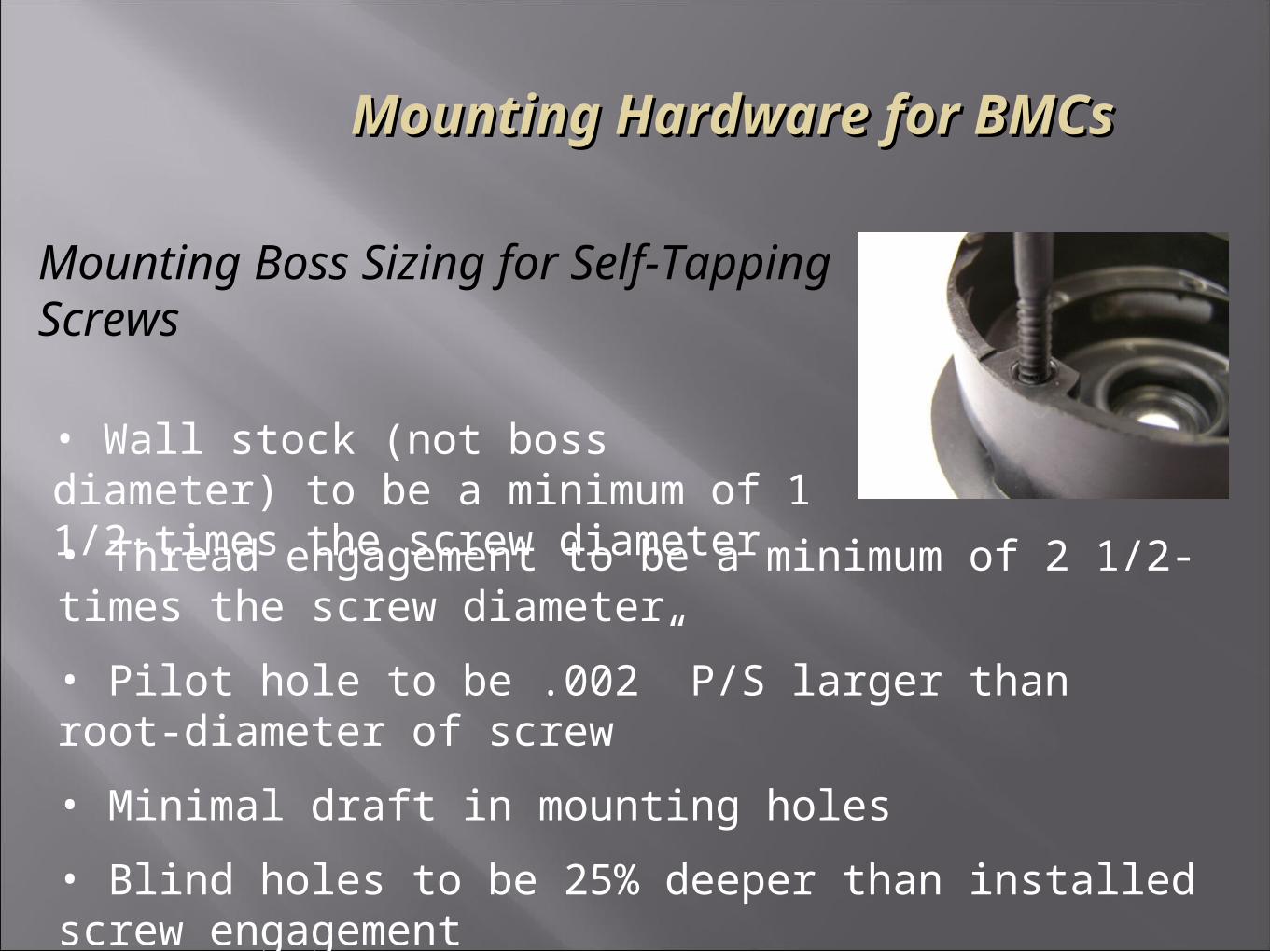
Mounting Boss Sizing for Self-Tapping Screws
• Wall stock (not boss diameter) to be a minimum of 1 1/2-times the screw diameter
• Thread engagement to be a minimum of 2 1/2-times the screw diameter
• Pilot hole to be .002” P/S larger than root-diameter of screw
• Minimal draft in mounting holes
• Blind holes to be 25% deeper than installed screw engagement
Mounting Hardware for BMCsMounting Hardware for BMCs
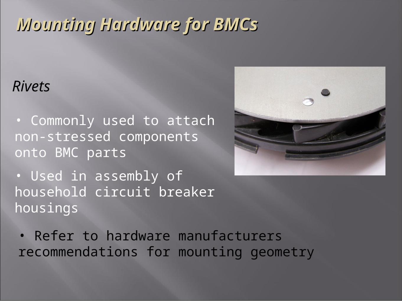
Rivets
• Commonly used to attach non-stressed components onto BMC parts
• Used in assembly of household circuit breaker housings
• Refer to hardware manufacturers recommendations for mounting geometry
Mounting Hardware for BMCsMounting Hardware for BMCs
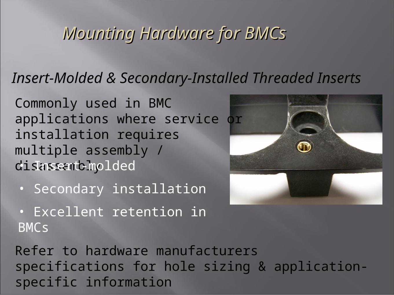
Insert-Molded & Secondary-Installed Threaded Inserts
Commonly used in BMC applications where service or installation requires multiple assembly / disassembly
• Insert-molded
• Secondary installation
• Excellent retention in BMCs
Refer to hardware manufacturers specifications for hole sizing & application-specific information
Snap Features in BMC Part DesignsSnap Features in BMC Part Designs
Given the range of flex modulus achievable in BMCs, snap details are possible provided that they can be designed with an interference that can operate within the flex-range of the material grade selected.
Feel free to contact BMCI’s Technical Group if you have a proposed snap design and would like to review it for feasibility in BMC.
Direct Conversion from Metal Direct Conversion from Metal DesignDesign
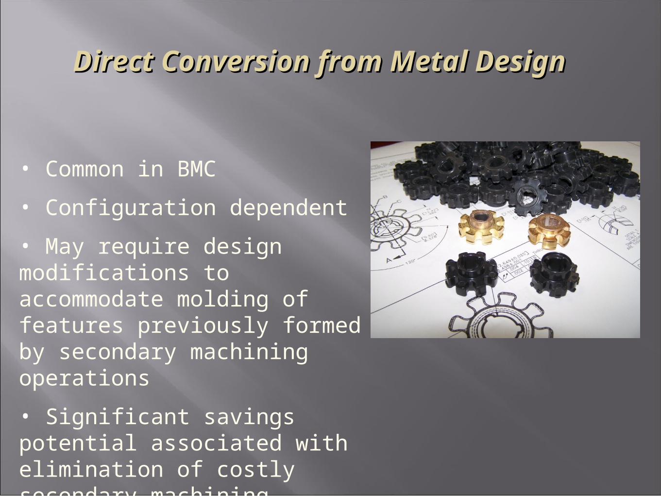
• Common in BMC
• Configuration dependent
• May require design modifications to accommodate molding of features previously formed by secondary machining operations
• Significant savings potential associated with elimination of costly secondary machining operations
Direct Conversion from Metal Direct Conversion from Metal DesignDesign
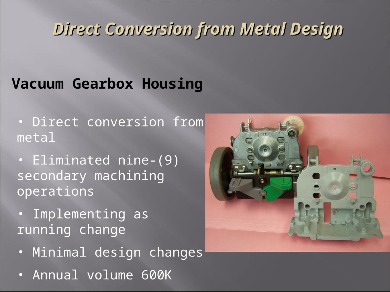
• Direct conversion from metal
• Eliminated nine-(9) secondary machining operations
• Implementing as running change
• Minimal design changes
• Annual volume 600K
• Annual savings : $690K
Vacuum Gearbox Housing
Part Consolidation Through Part Consolidation Through ConversionConversion

Part Consolidation Through Part Consolidation Through ConversionConversion
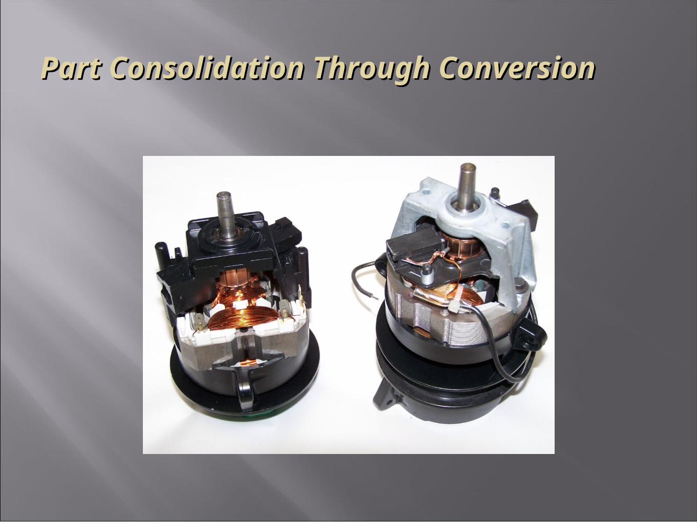
• Incorporation of multiple part features into one design
• Part count reduction
• Lower assembly tooling costs
• Reduced assembly labor
• Elimination of secondary machining operations
• Overall lower assembly cost
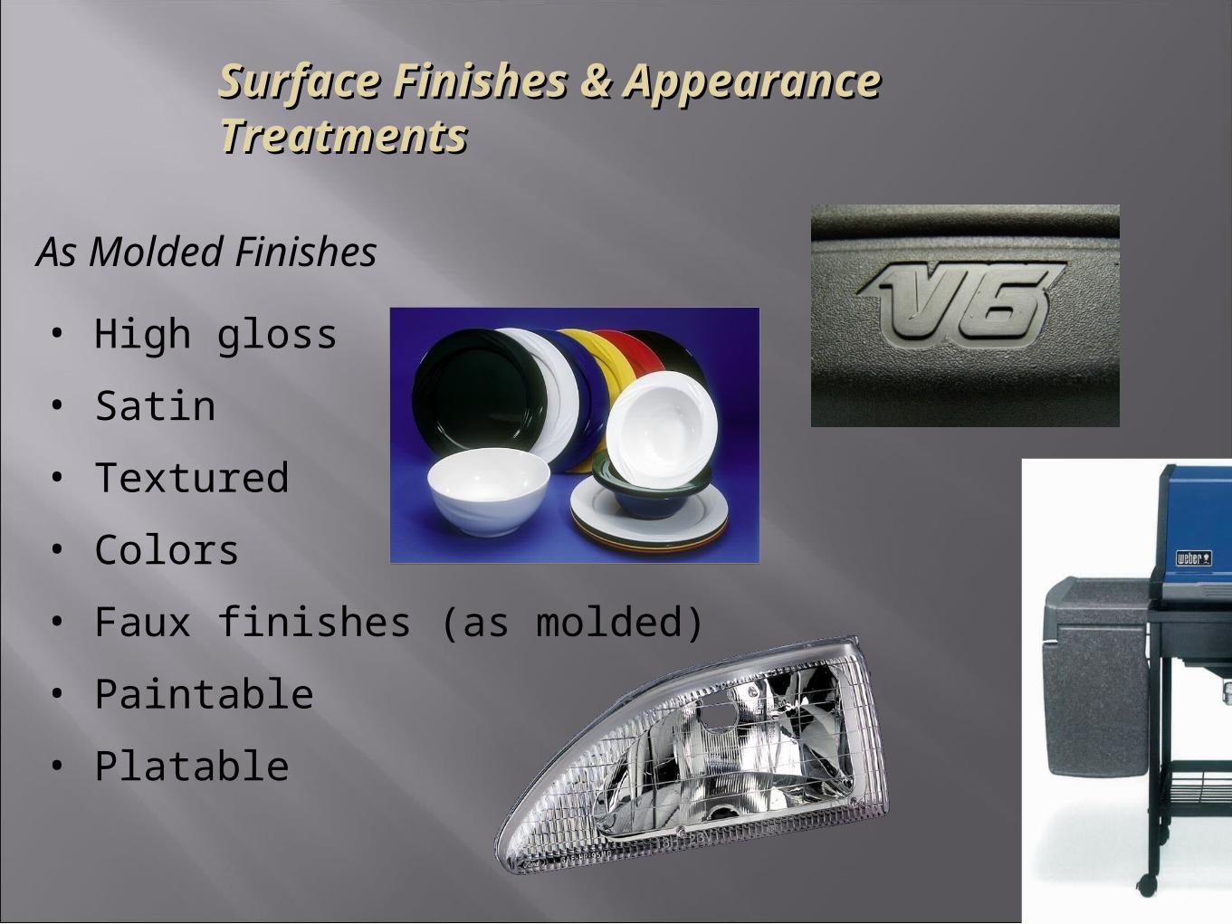
Surface Finishes & Appearance TreatmentsSurface Finishes & Appearance Treatments
As Molded Finishes
• High gloss
• Satin
• Textured
• Colors
• Faux finishes (as molded)
• Paintable
• Platable
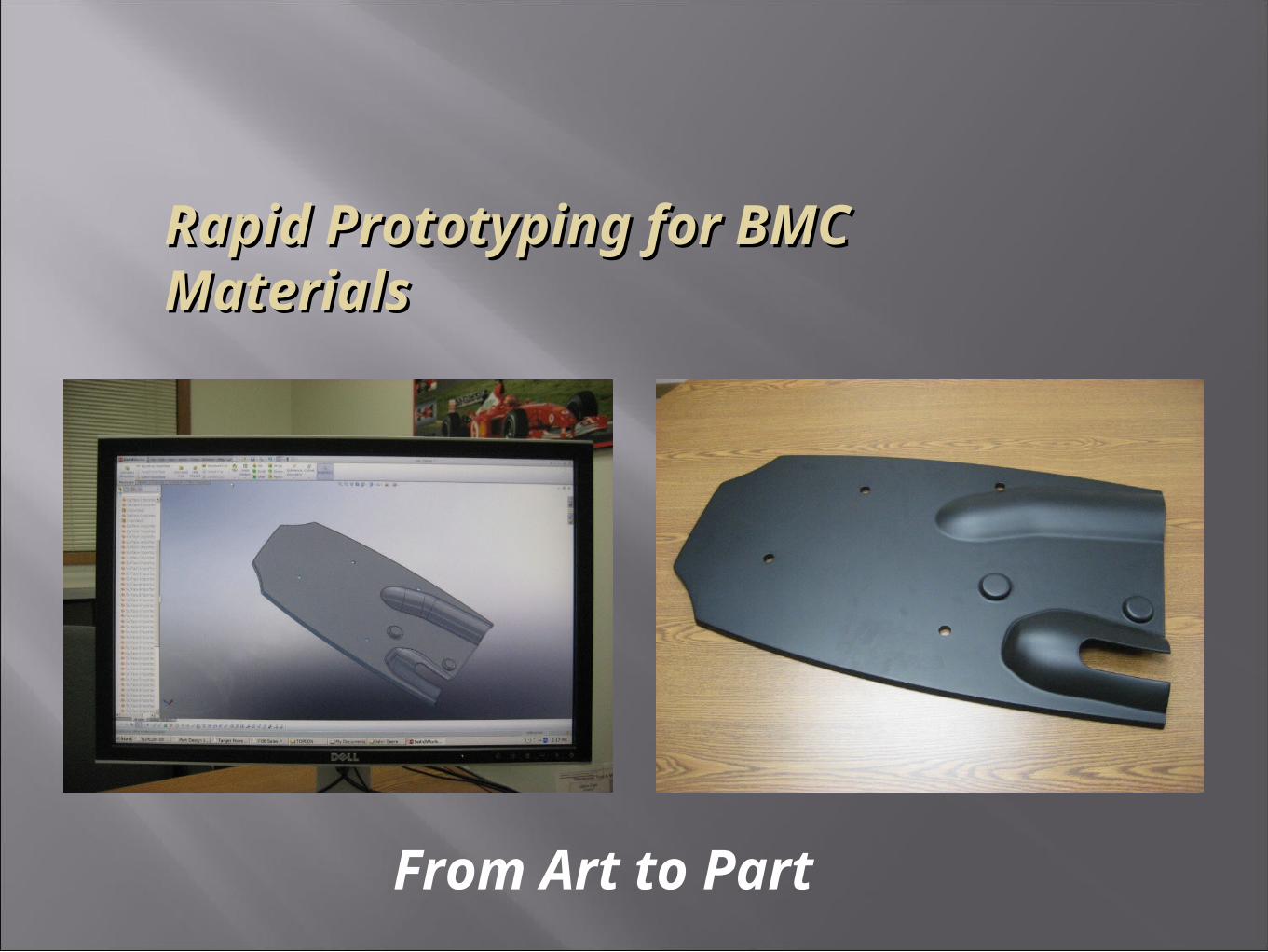
Rapid Prototyping for BMC MaterialsRapid Prototyping for BMC Materials
From Art to Part
Rapid Prototyping for BMC MaterialsRapid Prototyping for BMC Materials
Overview:The ability to quickly provide customers with prototype parts in our materials has proven to be both a valuable sales tool, and an effective method of shrinking product development lead times. Since BMC thermosets do not lend themselves to traditional “Rapid Prototyping” processes such as SLA (Stereo Lithography) of SLS (Selective Laser Sintering), we have developed our own prototyping process for providing net-shapes to our customers for evaluation.
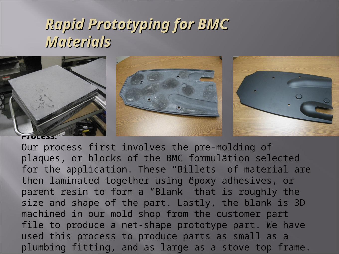
Rapid Prototyping for BMC MaterialsRapid Prototyping for BMC Materials
Process:Our process first involves the pre-molding of plaques, or blocks of the BMC formulation selected for the application. These “Billets” of material are then laminated together using epoxy adhesives, or parent resin to form a “Blank” that is roughly the size and shape of the part. Lastly, the blank is 3D machined in our mold shop from the customer part file to produce a net-shape prototype part. We have used this process to produce parts as small as a plumbing fitting, and as large as a stove top frame.
Rapid Prototyping for BMC MaterialsRapid Prototyping for BMC Materials
BMCI In-House Tooling / BMCI In-House Tooling / PrototypingPrototyping
• Part / product design assistance• Mold design• Prototype / production tooling• Prototype part construction• Tooling conversion for BMC materials
Rapid Prototyping for BMC MaterialsRapid Prototyping for BMC Materials
BMCI In-House Tooling / BMCI In-House Tooling / PrototypingPrototyping
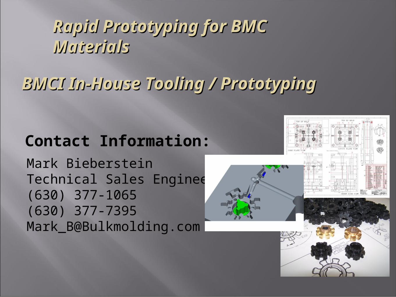
Contact Information:
Mark BiebersteinTechnical Sales Engineer(630) 377-1065(630) [email protected]