reducing uncertainty in emc · pdf fileapplied by product standards: cispr 11 (amd 2:2006-06...
TRANSCRIPT
Reducing Uncertainty in
EMC Measurements
Uncertainty
“In general, a standardized EMC test must be
developed such that reproducible results are
obtained if different parties perform the same test
with the same EUT.
However, various uncertainty sources and
influence quantities cause the reproducibility of a
standardized EMC test to be limited.”
(From CISPR 16-4-2 introduction)
Status of Cispr 14-4-2
First published in 2002 a Cispr 16-4.
Then split up in Cispr 16-4-2:2003 (same as Cispr 16-4).
Applied by product standards: Cispr 11 (Amd 2:2006-06
and Cispr 22:2005 (5th ed.).
Only a statement of ULab in the report needed.
New proposal to check if ULab exceeds UCispr.
Publication is due in 2010
CISPR16 Uncertainty
CISPR recommendations and technical reports
•CISPR 16-4-1 Uncertainty in standardized EMC Tests •CISPR 16-4-3 Statistical consideration in the determination of EMC
compliance of mass Product
•CISPR 16-4-4 Statistics of complaints and model for the calculation
of limits
•CISPR 16-4-5 Uncertainties, statistics and limits modelling –
Conditions for use of the alternative test methods
CISPR Editions on uncertainties in EMC measurements
•CISPR 16-4-2 Measurement instrumentation uncertainty

Focusing on Emission Testing
Measurement Instrumentation Uncertainty MUST be
taken into account when determining compliance or
non-compliance with a disturbance limit.
The Measurement Instrumentation Uncertainty for a
Test Laboratory (Ulab) MUST be evaluated for the
measurements addressed in CISPR 16-4-2 clauses,
taking into account every single quantity listed there.
Focusing on Emission Testing
CISPR 16-4-2 Standard clearly defines
Uncertainty topics for Emission Tests, whose
most relevant contributions come from:
- EMI/EMC Receivers
- Test Set-Up (layout, cables, adapters, site attenuation,…)
- LISNs and AMNs in general (ISNs, CDNs, Voltage
Probes,…)
- Absorbing Clamps
- Antennas
- Coupling between above components
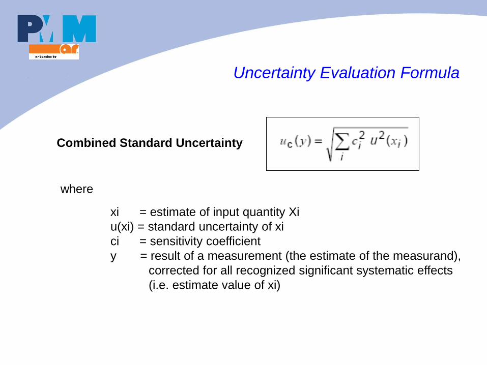
Uncertainty Evaluation Formula
Combined Standard Uncertainty
where
xi = estimate of input quantity Xi
u(xi) = standard uncertainty of xi
ci = sensitivity coefficient
y = result of a measurement (the estimate of the measurand),
corrected for all recognized significant systematic effects
(i.e. estimate value of xi)
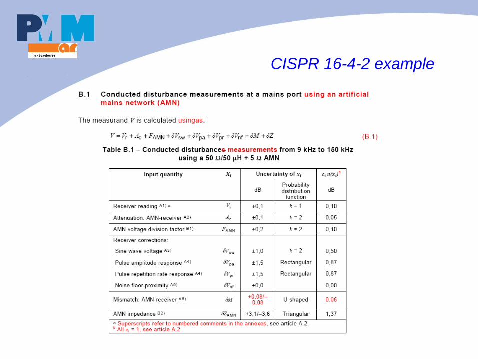
CISPR 16-4-2 example
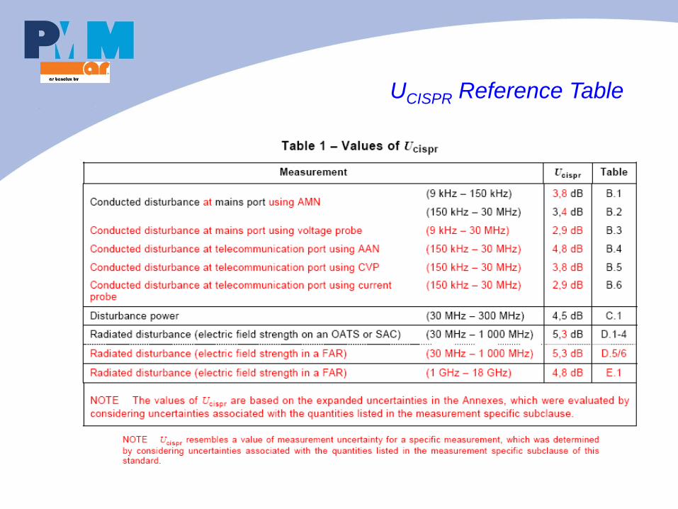
UCISPR Reference Table
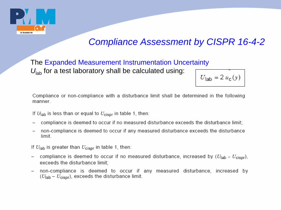
Compliance Assessment by CISPR 16-4-2
The Expanded Measurement Instrumentation Uncertainty
Ulab for a test laboratory shall be calculated using:
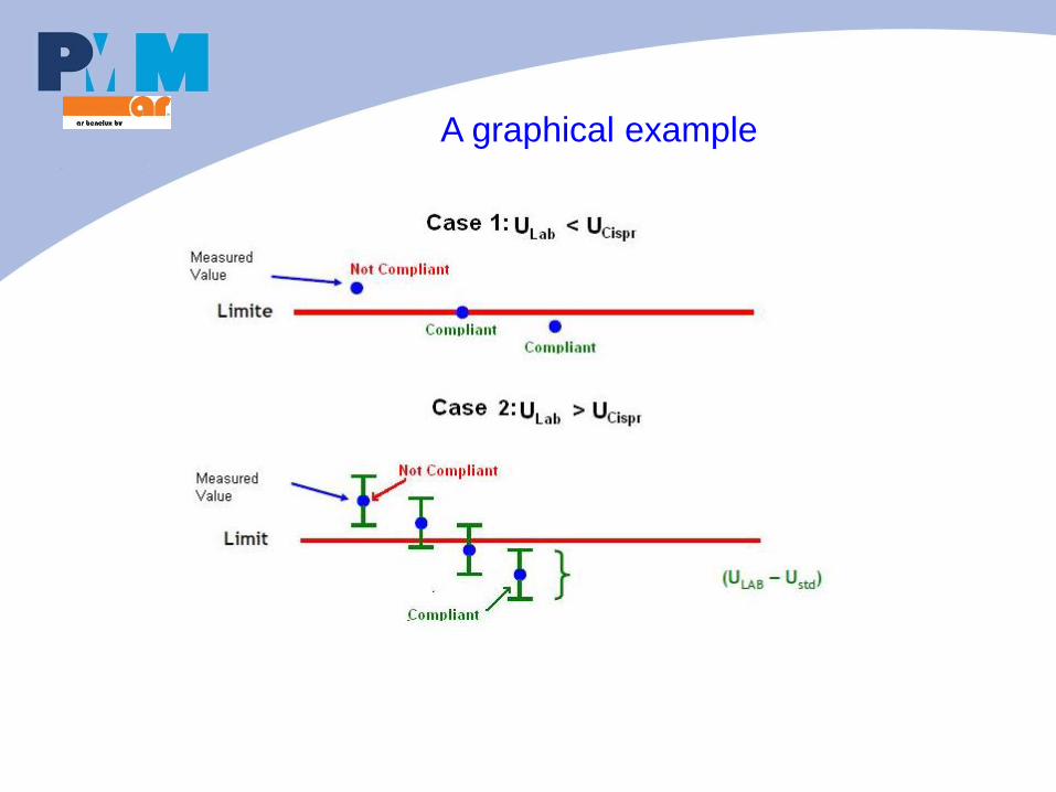
A graphical example
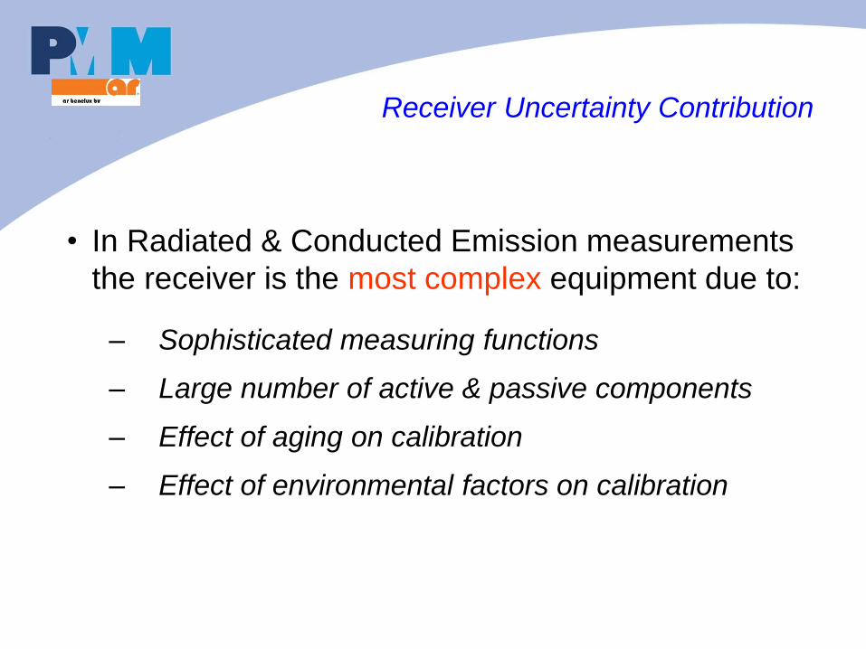
Receiver Uncertainty Contribution
• In Radiated & Conducted Emission measurements
the receiver is the most complex equipment due to:
– Sophisticated measuring functions
– Large number of active & passive components
– Effect of aging on calibration
– Effect of environmental factors on calibration
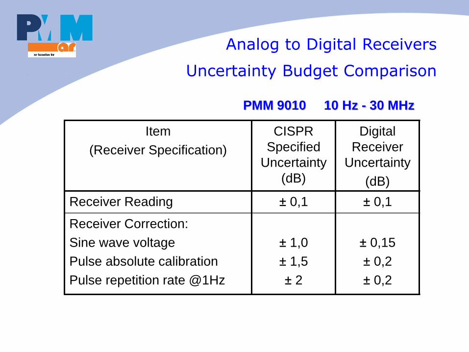
Item
(Receiver Specification)
CISPR
Specified
Uncertainty
(dB)
Digital
Receiver
Uncertainty
(dB)
Receiver Reading ± 0,1 ± 0,1
Receiver Correction:
Sine wave voltage
Pulse absolute calibration
Pulse repetition rate @1Hz
± 1,0
± 1,5
± 2
± 0,15
± 0,2
± 0,2
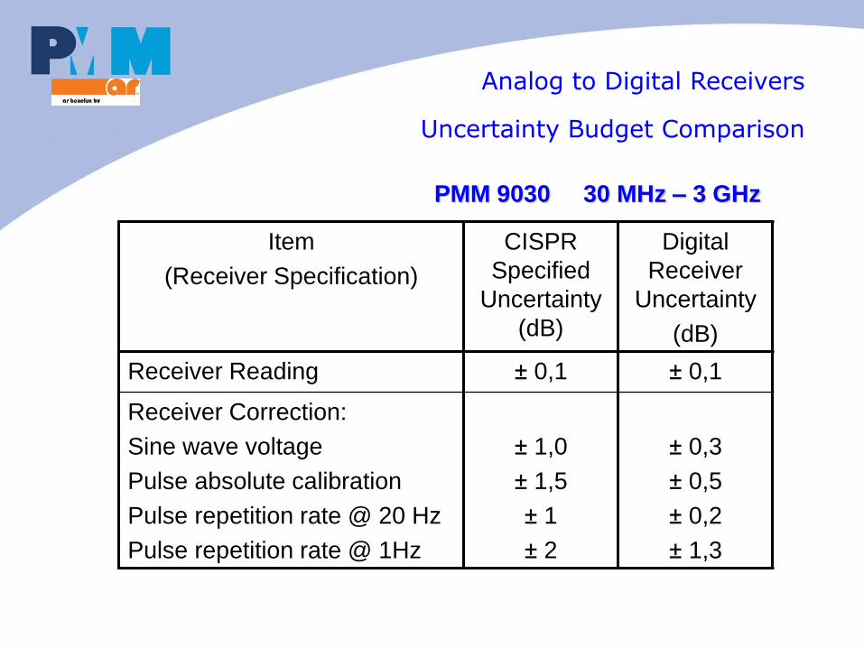
Analog to Digital Receivers
Uncertainty Budget Comparison
PMM 9010 10 Hz - 30 MHz
Item
(Receiver Specification)
CISPR
Specified
Uncertainty
(dB)
Digital
Receiver
Uncertainty
(dB)
Receiver Reading ± 0,1 ± 0,1
Receiver Correction:
Sine wave voltage
Pulse absolute calibration
Pulse repetition rate @ 20 Hz
Pulse repetition rate @ 1Hz
± 1,0
± 1,5
± 1
± 2
± 0,3
± 0,5
± 0,2
± 1,3
PMM 9030 30 MHz – 3 GHz
Analog to Digital Receivers
Uncertainty Budget Comparison
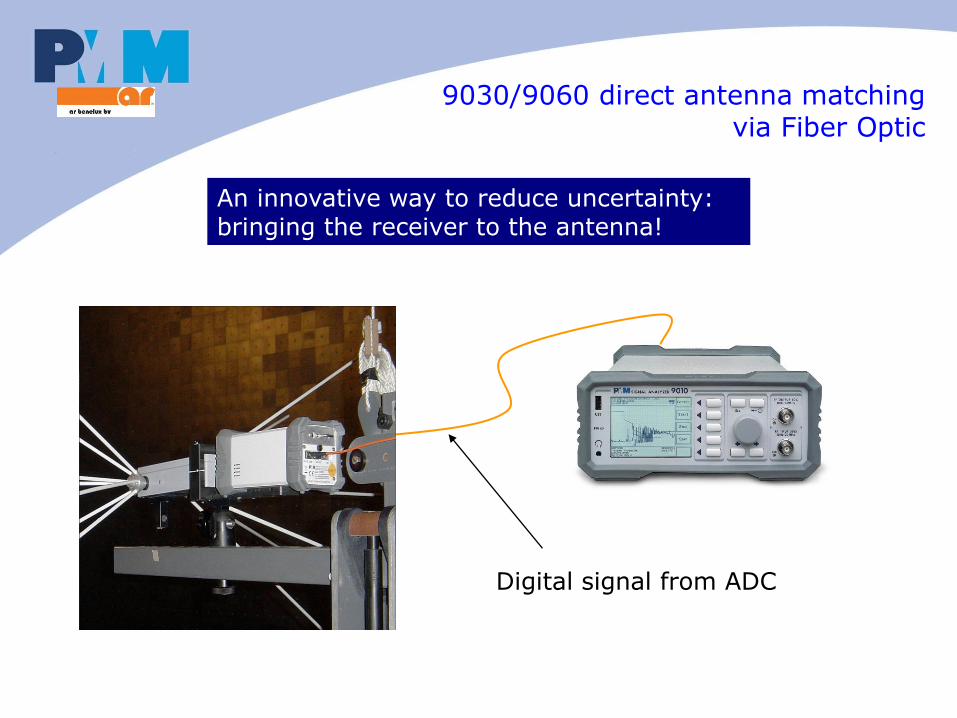
9030/9060 direct antenna matching via Fiber Optic
Digital signal from ADC
An innovative way to reduce uncertainty: bringing the receiver to the antenna!
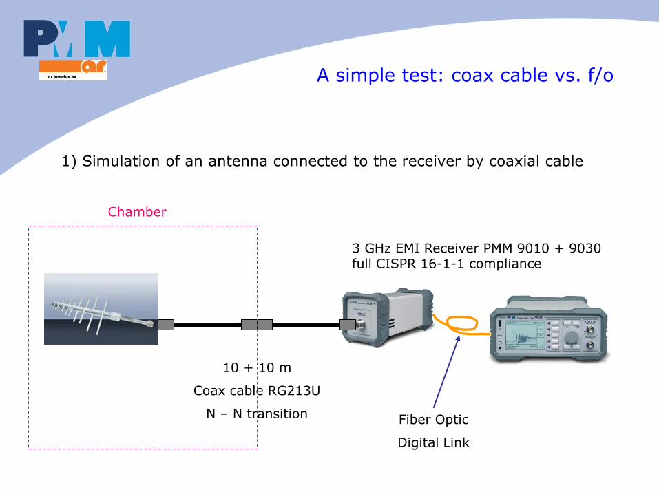
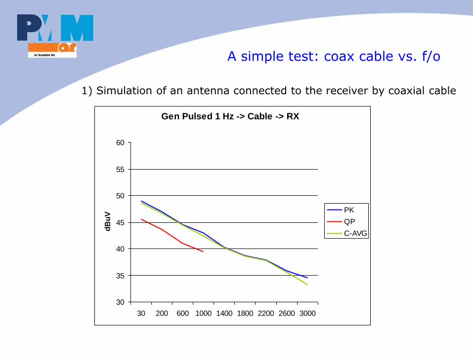
A simple test: coax cable vs. f/o
1) Simulation of an antenna connected to the receiver by coaxial cable
10 + 10 m
Coax cable RG213U
N – N transition
3 GHz EMI Receiver PMM 9010 + 9030 full CISPR 16-1-1 compliance
Fiber Optic
Digital Link
Chamber
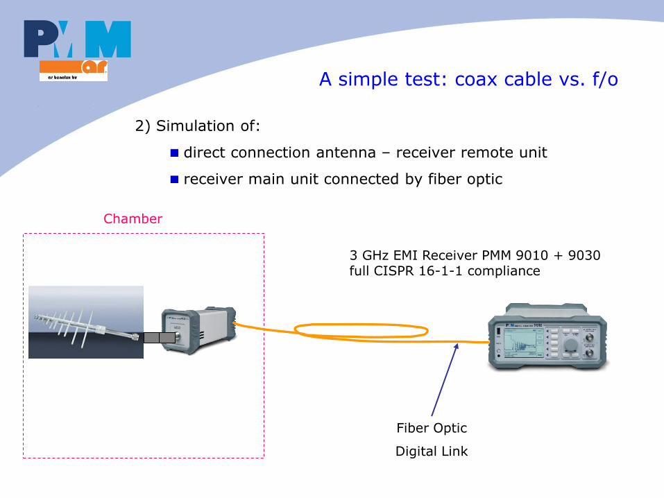
2) Simulation of:
direct connection antenna – receiver remote unit
receiver main unit connected by fiber optic
A simple test: coax cable vs. f/o
3 GHz EMI Receiver PMM 9010 + 9030 full CISPR 16-1-1 compliance
Fiber Optic
Digital Link
Chamber
A simple test: coax cable vs. f/o
1) Simulation of an antenna connected to the receiver by coaxial cable
Gen Pulsed 1 Hz -> Cable -> RX
30
35
40
45
50
55
60
30 200 600 1000 1400 1800 2200 2600 3000
dB
uV
PK
QP
C-AVG
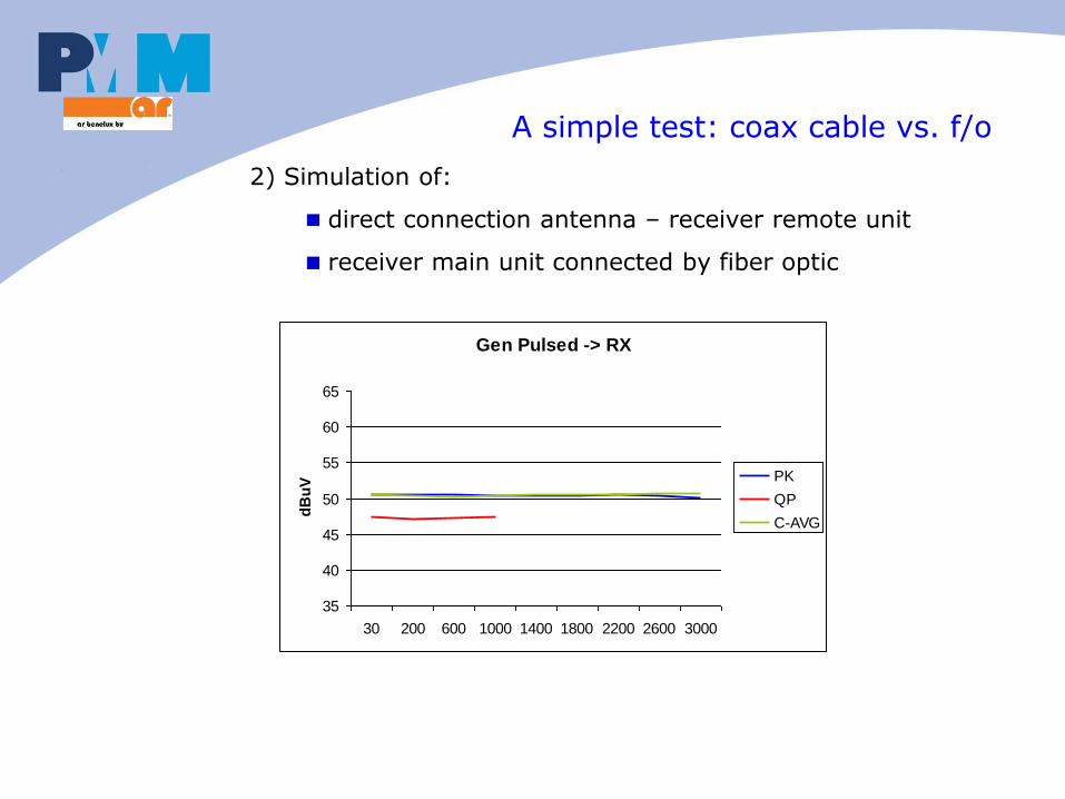
A simple test: coax cable vs. f/o
2) Simulation of:
direct connection antenna – receiver remote unit
receiver main unit connected by fiber optic
Gen Pulsed -> RX
35
40
45
50
55
60
65
30 200 600 1000 1400 1800 2200 2600 3000
dB
uV PK
QP
C-AVG
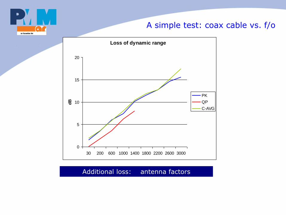
A simple test: coax cable vs. f/o
Loss of dynamic range
0
5
10
15
20
30 200 600 1000 1400 1800 2200 2600 3000
dB
PK
QP
C-AVG
Additional loss: antenna factors
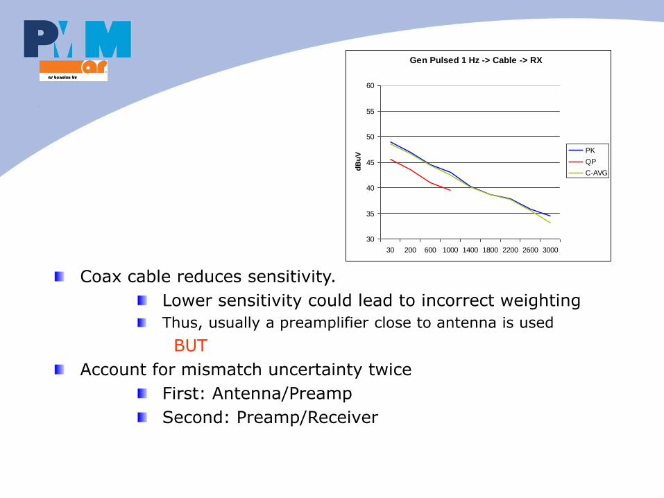
Coax cable reduces sensitivity.
Lower sensitivity could lead to incorrect weighting
Thus, usually a preamplifier close to antenna is used
BUT
Account for mismatch uncertainty twice
First: Antenna/Preamp
Second: Preamp/Receiver
Gen Pulsed 1 Hz -> Cable -> RX
30
35
40
45
50
55
60
30 200 600 1000 1400 1800 2200 2600 3000
dB
uV
PK
QP
C-AVG
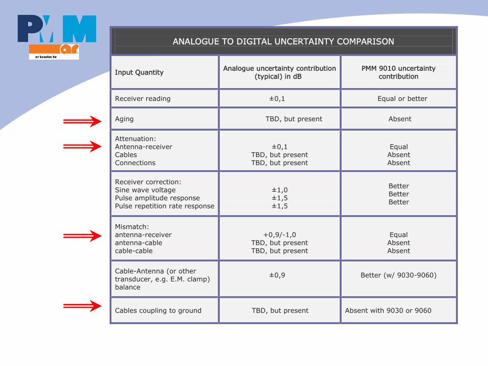
ANALOGUE TO DIGITAL UNCERTAINTY COMPARISON
Input Quantity
Analogue uncertainty contribution
(typical) in dB
PMM 9010 uncertainty
contribution
Receiver reading ±0,1 Equal or better
Aging TBD, but present Absent
Attenuation: Antenna-receiver Cables Connections
±0,1
TBD, but present TBD, but present
Equal
Absent Absent
Receiver correction: Sine wave voltage Pulse amplitude response Pulse repetition rate response
±1,0 ±1,5 ±1,5
Better Better Better
Mismatch: antenna-receiver antenna-cable cable-cable
+0,9/-1,0
TBD, but present TBD, but present
Equal Absent Absent
Cable-Antenna (or other transducer, e.g. E.M. clamp) balance
±0,9
Better (w/ 9030-9060)
Cables coupling to ground
TBD, but present
Absent with 9030 or 9060
Other benefits from Split Architecture
No expensive coaxial cables
No cable loss
No cable/antenna coupling
No cable scattering
No connectors loss
Antenna decoupling not needed
Higher flexibility of Optical cable
Longer connection distance (100 m)