reduction of vibrations and noise using aa7020/fe2o3 · pdf filereduction of vibrations and...
TRANSCRIPT
International Journal of Scientific & Engineering Research, Volume 6, Issue 9, September-2015 685 ISSN 2229-5518
IJSER © 2015 http://www.ijser.org
Reduction of Vibrations and Noise using AA7020/Fe2O3 Nano Composite Gear Box in
Lathe A. Chennakesava Reddy
Abstract— If the vibration amplitudes of a machine exceed the severity limit as per codes, the machine should be shut down to identify the faults so that remedial action can be taken to keep the machine safe. Exposure to excessive noise can damage hearing, and it is important to understand the effects of this kind of noise, particularly because such exposure is avoidable. The aim of the present work was to reduce vibrations and noise in the lathe machines using AA7020/Fe2O3 nano composite gears in the gear box. As per IRD General Machinery Vibration Severity Chart, the condition of the lathe is VERY GOOD as the vibration have been reduced 100 VdB. The noise levels have been reduced within the permissible limit of 97 dB for the lathe machines with gear box having AA7020/Fe2O3 nano composite gears.
Index Terms— Vibration, noise, lathe, gear box, AA7020, iron oxide, nanocomposite gears. —————————— ——————————
1. INTRODUCTION EARS are critical components of a power transmission system used in machine tools like lathes. Legal regula-tions and customer demands arising from an in-
creased focus on environmental and quality issues can re-sult in requirements to lower vibrations and noise from gearboxes. Researchers and gear-industry experts agree that a transmission error is an important excitation mecha-nism for vibrations and noise [1]. Welbourn [2] defined transmission error as ‘the difference between the actual position of the output gear and the position it would occu-py if the gear drive were perfectly conjugate.’ A general design requirement is to keep gear whine noise at least 15 dB lower than the noise from other sources, such as engine or machine. Sweeney [3] carried out a test program to in-vestigate the effects of mean torque and speed on transmis-sion error, casing vibration, noise and torque fluctuations. He found that it was difficult to draw any broad conclu-sions about the relationships of various quantities meas-ured.
The objective of this paper was to experimentally inves-tigate the influence of different types of gear materials to reduce vibrations and noise in the lathes used in an engi-neering workshop. To achieve the goals of the proposed project the metal gears were replaced by AA7020/Fe2O3 nano composite gears.
2. GEAR TRANSMISSION SYSTEM USED IN A LATHE Lathe is a machine tool which rotates the workpiece on its axis to perform various operations such as cutting, knurling, drilling, facing, taper turning, thread cutting, etc., with tools that are applied to the workpiece to create an object which has symmetry about an axis of rotation. The headstock of a lathe carries the head spindle and the mech-anism for driving it. It comprises a spindle and mechanism for driving and altering the spindle speed. The spindle is
hollow throughout its length so that bars or rods can be passed through it from the left and held in a chuck at the nose. The chuck end of the spindle is bored to a Morse ta-per to receive the solid center. At the other end of the spin-dle is the gear by which the spindle drives the feed and the screw-cutting mechanism through a gear train located on the left end of the lathe.
The spindle is subjected to considerable torque because it drives the work against the resistance of the cutting tool, as well as driving the carriage that feeds the tool into the workpiece. Because of the torque and pressure applied to the spindle, adequate lubrication and accurately adjusted bearings are absolutely necessary. The headstocks are clas-sified into two categories based on the driving mechanism:
• all-belt driven headstock • all-geared headstock
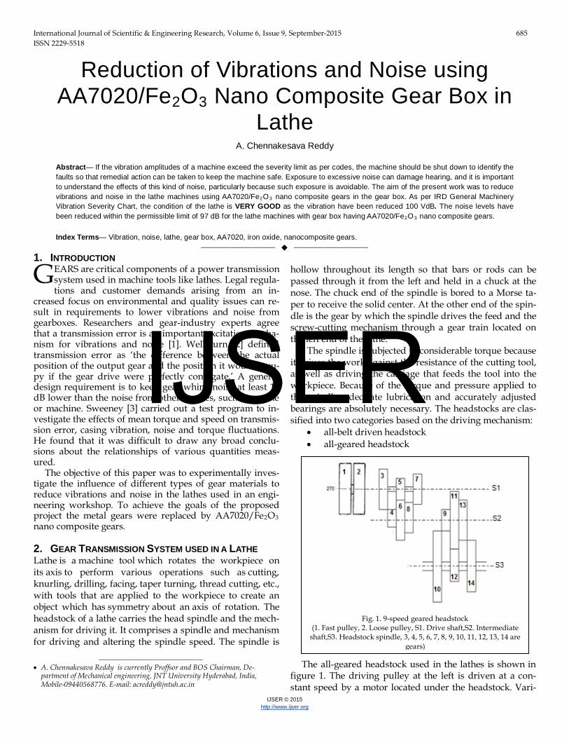
The all-geared headstock used in the lathes is shown in figure 1. The driving pulley at the left is driven at a con-stant speed by a motor located under the headstock. Vari-
G
———————————————— • A. Chennakesava Reddy is currently Proffsor and BOS Chairman, De-
partment of Mechanical engineering, JNT University Hyderabad, India, Mobile-09440568776. E-mail: [email protected]
Fig. 1. 9-speed geared headstock
(1. Fast pulley, 2. Loose pulley, S1. Drive shaft,S2. Intermediate shaft,S3. Headstock spindle, 3, 4, 5, 6, 7, 8, 9, 10, 11, 12, 13, 14 are
gears)
IJSER
International Journal of Scientific & Engineering Research Volume 6, Issue 9, September-2015 ISSN 2229-5518
686
IJSER © 2015 http://www.ijser.org
ous combinations of gears in the headstock transmit power from the drive shaft to the headstock spindle through an intermediate shaft. The speed-change levers are used to shift the sliding gears on the drive shaft and the intermedi-ate shaft to line up the gears in different combinations. This produces the gear ratios needed to obtain the various spin-dle speeds. The lathe used in the present work had 9 speeds powered by 8 kW motor. The speed range was 90 to 1500 rpm.
Preferred number: 1.06, 1.12, 1.26, 1.41, 1.58, 1.78, 2.
The nearest preferred number in the list is 1.41. The var-ious speeds in ascending order are as follows: n1 =1500; n2 =1062; n3 =755; n4 =535; n5 =380; n6 =270; n7 =191, n8 =135; n9 = 90
According to the considerations of slip and strength, the speed ratio allowable at the pulleys is 5 to 7. So the primary speed is between 1440/7 = 206 and 1440/5 = 288 assuming motor rating to be 444 V at 1440 rpm. Therefore, the prima-ry speed of 270 rpm is considered. For economy and com-pactness, narrow ray diagram is preferred. The ray dia-gram is shown in figure 2.
Let the minimum number of teeth on the gear is 20. Then
T3 T4⁄ = 1.99; T4 = 20 and T3 = 40
As the centre distance remains constant,
T3 + T4 = T5 + T6 = 60
T5T6
= 1.41; T4 = 60 2.41⁄ = 25; T5 = 35
T7 + T8 = T3 + T4 = T5 + T6 = 60
T7 = T8 = 30
For speeds, 1500, 1072 and 755
T9T10
= 2.8; T9 = 20; T10 = 56
For speeds, 535, 380 and 270
T11T12
= 1.92; T11 = 50; T12 = 26
For speeds, 191, 135 and 90
T13 T14⁄ = 1.0; T13 = 38; T14 = 38
The structural diagram is shown in figure 3.
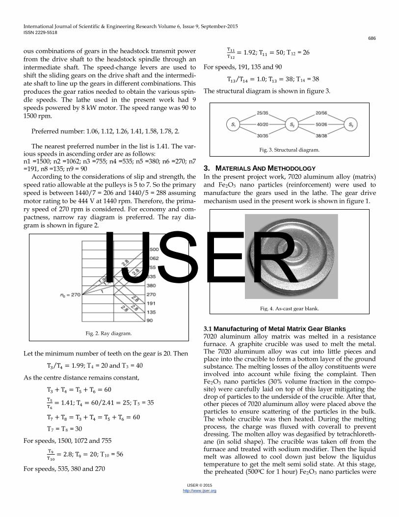
3. MATERIALS AND METHODOLOGY In the present project work, 7020 aluminum alloy (matrix) and Fe2O3 nano particles (reinforcement) were used to manufacture the gears used in the lathe. The gear drive mechanism used in the present work is shown in figure 1. 3.1 Manufacturing of Metal Matrix Gear Blanks 7020 aluminum alloy matrix was melted in a resistance furnace. A graphite crucible was used to melt the metal. The 7020 aluminum alloy was cut into little pieces and place into the crucible to form a bottom layer of the ground substance. The melting losses of the alloy constituents were involved into account while fixing the complaint. Then Fe2O3 nano particles (30% volume fraction in the compo-site) were carefully laid on top of this layer mitigating the drop of particles to the underside of the crucible. After that, other pieces of 7020 aluminum alloy were placed above the particles to ensure scattering of the particles in the bulk. The whole crucible was then heated. During the melting process, the charge was fluxed with coverall to prevent dressing. The molten alloy was degasified by tetrachloreth-ane (in solid shape). The crucible was taken off from the furnace and treated with sodium modifier. Then the liquid melt was allowed to cool down just below the liquidus temperature to get the melt semi solid state. At this stage, the preheated (5000C for 1 hour) Fe2O3 nano particles were
Fig. 2. Ray diagram.
Fig. 3. Structural diagram.
Fig. 4. As-cast gear blank.
IJSER

International Journal of Scientific & Engineering Research Volume 6, Issue 9, September-2015 ISSN 2229-5518
687
IJSER © 2015 http://www.ijser.org
added to the liquid melt. The molten alloy and Fe2O3 nano particles were thoroughly stirred manually for 15 minutes. After manual steering, the semisolid liquid melt was re-heated to a full liquid state in the resistance furnace fol-lowed by an automatic mechanical stirring using a mixer to make the melt homogenous for about 10 minutes at 200 rpm. The temperature of melted metal was measured using a dip type thermocouple. The preheated cast iron die was filled with dross-removed melt by the compressed (3.0 bar) argon gas [4, 5]. As-cast typical gear blank is shown in fig-ure 4. 3.2 Manufacturing of Gears The gears were machined on a milling machine. The gear blank was mounted on a mandrel which was supported between the center of the dividing head and another center at the other end, as shown in figure 5. At a time, one tooth was cut by the milling cutter, and the dividing head was used to index the workpiece to the next required tooth. The cutter was selected according to module and number of gear teeth to cut. This cutter was mounted on the milling arbor. Before the gear was cut, it was necessary to have the cutter centered accurately relative to the gear holding mandrel. One way was to adjust the machine table vertical-ly and horizontally until one corner of the cutter just touched the mandrel on one side. Both dials (of the table and the knee) were then set to zero. The table was then ad-justed for the cutter to just touch on the other side of the mandrel with vertical dial showing zero. The reading of the horizontal feed screw was read. This reading, divided by two gave the central position of the mandrel relative to the cutter. When the table was set centrally in this manner, it should be locked in that position. The table was then fed vertically so that the blank just touched the cutter. Vertical dial was then set to zero. This was needed to give the depth of cut on the gear blank.
With these settings the machine was started and trav-ersed along the axis of the gear blank to cut the tooth over
the entire width of the gear. Depth was increased slowly until it reached the full depth of the tooth. After one tooth space was cut, the blank was indexed through 1/z revolu-tion by means of the dividing head, and the process was repeated until all the teeth were cut. The dimensions of the gears manufactured are given table 2. Samples of manufac-tured AA7020/Fe2O3 nano composite gears are shown in figure 6.
TABLE 1 Designation and Dimensions of Gears
Sl.no. Pitch diameter, mm Quantity 3 200 1 4 100 1
5 125 1
6 175 1
7 150 1
8 150 1
9 100 1
10 280 1
11 250 1
12 130 1
13 190 1
14 190 1
3.3 Testing for Mechanical Properties The samples were machined to get flat-rectangular speci-
Fig. 5. Manufacturing of gears on a milling machine.
Fig. 6. Manufactured gears on milling machine.
Fig. 7. Dimensions of flat tensile specimen.
IJSER
International Journal of Scientific & Engineering Research Volume 6, Issue 9, September-2015 ISSN 2229-5518
688
IJSER © 2015 http://www.ijser.org
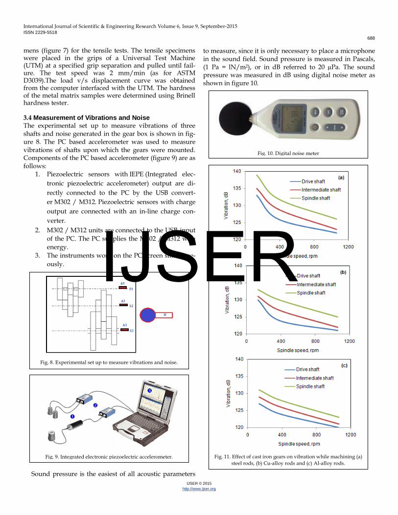
mens (figure 7) for the tensile tests. The tensile specimens were placed in the grips of a Universal Test Machine (UTM) at a specified grip separation and pulled until fail-ure. The test speed was 2 mm/min (as for ASTM D3039).The load v/s displacement curve was obtained from the computer interfaced with the UTM. The hardness of the metal matrix samples were determined using Brinell hardness tester. 3.4 Measurement of Vibrations and Noise The experimental set up to measure vibrations of three shafts and noise generated in the gear box is shown in fig-ure 8. The PC based accelerometer was used to measure vibrations of shafts upon which the gears were mounted. Components of the PC based accelerometer (figure 9) are as follows:
1. Piezoelectric sensors with IEPE (Integrated elec-tronic piezoelectric accelerometer) output are di-rectly connected to the PC by the USB convert-er M302 / M312. Piezoelectric sensors with charge output are connected with an in-line charge con-verter.
2. M302 / M312 units are connected to the USB-input of the PC. The PC supplies the M302 / M312 with energy.
3. The instruments work on the PC-screen simultane-ously.
Sound pressure is the easiest of all acoustic parameters
to measure, since it is only necessary to place a microphone in the sound field. Sound pressure is measured in Pascals, (1 Pa = lN/m2), or in dB referred to 20 µPa. The sound pressure was measured in dB using digital noise meter as shown in figure 10.
Fig. 11. Effect of cast iron gears on vibration while machining (a)
steel rods, (b) Cu-alloy rods and (c) Al-alloy rods.
Fig. 8. Experimental set up to measure vibrations and noise.
Fig. 9. Integrated electronic piezoelectric accelerometer.
Fig. 10. Digital noise meter
IJSER
International Journal of Scientific & Engineering Research Volume 6, Issue 9, September-2015 ISSN 2229-5518
689
IJSER © 2015 http://www.ijser.org
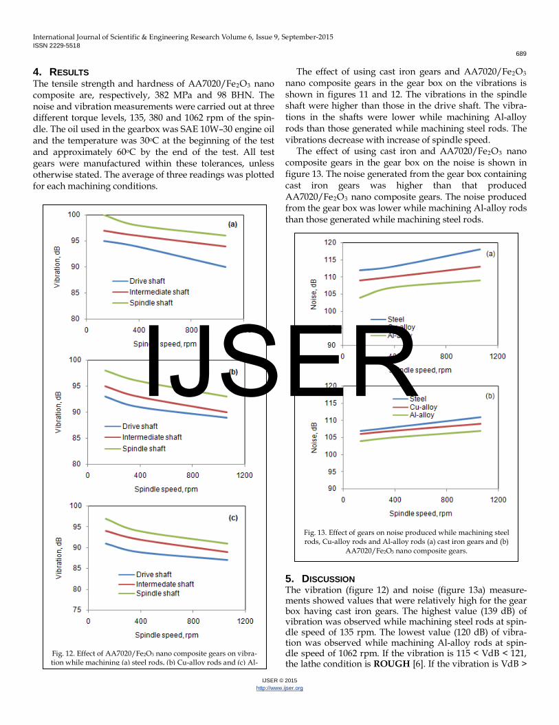
4. RESULTS The tensile strength and hardness of AA7020/Fe2O3 nano composite are, respectively, 382 MPa and 98 BHN. The noise and vibration measurements were carried out at three different torque levels, 135, 380 and 1062 rpm of the spin-dle. The oil used in the gearbox was SAE 10W–30 engine oil and the temperature was 30oC at the beginning of the test and approximately 60oC by the end of the test. All test gears were manufactured within these tolerances, unless otherwise stated. The average of three readings was plotted for each machining conditions.
The effect of using cast iron gears and AA7020/Fe2O3 nano composite gears in the gear box on the vibrations is shown in figures 11 and 12. The vibrations in the spindle shaft were higher than those in the drive shaft. The vibra-tions in the shafts were lower while machining Al-alloy rods than those generated while machining steel rods. The vibrations decrease with increase of spindle speed.
The effect of using cast iron and AA7020/Fe2O3 nano composite gears in the gear box on the noise is shown in figure 13. The noise generated from the gear box containing cast iron gears was higher than that produced AA7020/Fe2O3 nano composite gears. The noise produced from the gear box was lower while machining Al-alloy rods than those generated while machining steel rods. 5. DISCUSSION The vibration (figure 12) and noise (figure 13a) measure-ments showed values that were relatively high for the gear box having cast iron gears. The highest value (139 dB) of vibration was observed while machining steel rods at spin-dle speed of 135 rpm. The lowest value (120 dB) of vibra-tion was observed while machining Al-alloy rods at spin-dle speed of 1062 rpm. If the vibration is 115 < VdB < 121, the lathe condition is ROUGH [6]. If the vibration is VdB >
Fig. 12. Effect of AA7020/Fe2O3 nano composite gears on vibra-tion while machining (a) steel rods, (b) Cu-alloy rods and (c) Al-
Fig. 13. Effect of gears on noise produced while machining steel rods, Cu-alloy rods and Al-alloy rods (a) cast iron gears and (b)
AA7020/Fe2O3 nano composite gears.
IJSER
International Journal of Scientific & Engineering Research Volume 6, Issue 9, September-2015 ISSN 2229-5518
690
IJSER © 2015 http://www.ijser.org
121, the lathe condition is VERY ROUGH. Machines with vibration levels above the ROUGH region should be ana-lyzed immediately for cause determination and shut down at the earliest opportunity for correction. This situation was aroused due to machining under dry conditions. When water soluble cutting oil was employed while tuning rods on the lathe, the vibration was reduced to 112 which is near to FAIR (103 < VdB < 109) condition [6]. The noise level was come down from 118 dB (figure 14a) to 106 dB (figure 14). The permissible noise limit for the machines is 108 dB [7]. The marginal difference might be due to transmission error from the drive shaft to the spindle shaft. The trans-mission error would result from teeth disengagement, shaft deformation, lead crowning, involute alignment error, helix angle error and backlash error. Kohler and Regan [8] inves-tigated the effect of pitch errors on transmission error of a gear pair. Flodin [9] investigated mild wear of spur and helical gears. Wear simulations showed that for helical gears without lead crowning or tip relief, the simulated wear reduced calculated transmission error.
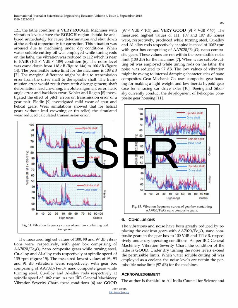
The measured highest values of 100, 98 and 97 dB vibra-tions were, respectively, with gear box comprising of AA7020/Fe2O3 nano composite gears while turning steel, Cu-alloy and Al-alloy rods respectively at spindle speed of 135 rpm (figure 15). The measured lowest values of 96, 93 and 91 dB vibrations were, respectively, with gear box comprising of AA7020/Fe2O3 nano composite gears while turning steel, Cu-alloy and Al-alloy rods respectively at spindle speed of 1062 rpm. As per IRD General Machinery Vibration Severity Chart, these conditions [6] are GOOD
(97 < VdB < 103) and VERY GOOD (91 < VdB < 97). The measured highest values of 111, 109 and 107 dB noises were, respectively, produced while turning steel, Cu-alloy and Al-alloy rods respectively at spindle speed of 1062 rpm with gear box comprising of AA7020/Fe2O3 nano compo-site gears. These values are not within the permissible noise limit (108 dB) for the machines [7]. When water soluble cut-ting oil was employed while tuning rods on the lathe, the noise was reduced to 97 dB. The low values of vibration might be owing to internal damping characteristics of nano composites. Gear Mechanic Co. uses composite gear hous-ing for making a light weight and low inertia hypoid gear case for a racing car drive axles [10]. Boeing and Sikor-sky currently conduct the development of helicopter com-posite gear housing [11].
6. CONCLUSIONS The vibrations and noise have been greatly reduced by re-placing the cast iron gears with AA7020/Fe2O3 nano com-posite gears in the gear box to 100 VdB and 111 dB, respec-tively under dry operating conditions. As per IRD General Machinery Vibration Severity Chart, the condition of the lathe is GOOD. Under dry turning the noise levels exceed the permissible limits. When water soluble cutting oil was employed as a coolant, the noise levels are within the per-missible noise limit (97 dB) for the machines.
ACKNOWLEDGEMENT The author is thankful to All India Council for Science and
Fig. 14. Vibration frequency curves of gear box containing cast
iron gears.
Fig. 15. Vibration frequency curves of gear box containing
AA7020/Fe2O3 nano composite gears.
IJSER

International Journal of Scientific & Engineering Research Volume 6, Issue 9, September-2015 ISSN 2229-5518
691
IJSER © 2015 http://www.ijser.org
Technology (AICTE), New Delhi for sponsoring this pro-ject. The File No. is 8023/RID/RPS-2011-12 dated: 02.12.2011.
REFERENCES [1] M. Akerblom. “Gear Noise and Vibration – A Literature Survey,”
TRITA-MMK 2001:11 / ISSN 1400-1179 / ISRN/KTH/MMK/R-01/11-SE, Stockholm 2001.
[2] D. B. Welbourn. “Fundamental Knowledge of Gear Noise – A Sur-vey” Proceedings IMechE Vibrations in Transmissions Systems Con-ference, The Institution of Mechanical Engineers , Cranfield, UK, July 1979, pp. 9–14.
[3] P. J. Sweeney, “Transmission error measurement and analysis,” Uni-versity of New South Wales, Doctoral Thesis, 1995.
[4] A. Chennakesava Reddy, “Strengthening mechanisms and fracture behavior of 7072Al/Al2O3 metal matrix composites,” International Journal of Engineering Science and Technology, vol.3, no.7, pp. 6090-6100, 2011.
[5] Tensile fracture behavior of 7072/SiCp metal matrix composites fab-ricated by gravity die casting process,” Materials Technology: Ad-vanced Performance Materials, vol.26, no.5, pp. 257-262, 2011.
[6] The IRD General machinery Vibration Severity Chart, Entek IRD International, pp.1-25, https://rockwellautomation.custhelp.com.
[7] Noise measurement Manual, Prepared by: Environmental Perfor-mance and Coordination Branch, Department of Environment and Heritage Protection, The State of Queensland, 2013.
[8] K. Kohler, R. Regan, “The Derivation of Gear Transmission Error from Pitch Error Records,” vol.61, The Institution of Mechanical En-gineers, 1985.
[9] A. Flodin, “Wear of Spur and Helical Gears” Royal Institute of Tech-nology, Stockholm, Doctoral Thesis, 2000.
[10] https://en.wikipedia.org/wiki/Composite_gear_housing [11] Affordable Helicopter Drive Train Hous-
ings, https://en.wikipedia.org/wiki/Gear_housing, Retrieved 5 January 2012.
IJSER