redundancy for fault-tolerance and avb – overview of … of the proposal 1 2 3 4 first ta 1 2 3 4...
TRANSCRIPT

AVB for low latency / industrial automation networks:
Redundancy for fault-tolerance and AVB –Overview of the simultaneous multi-path proposal
Oliver Kleineberg, Hirschmann Automation & Control([email protected])
IEEE 802 Plenary Meeting, March 2012, Waikoloa, USA

2
Agenda:
� Assumptions and Requirements
� Overview of the Proposal
� Example application scenarios and benefits
� Conclusion
Agenda

3
Assumptions and Requirements
Assumptions and Requirements

4
Assumptions for the use of AVB Gen.2 in industrial and automotive environments:
� Standardization of Ethernet technology is still important (probably now more than ever), but new and very specific application demands will still outpace standardization or will never be truly standardized (in the near future)
� Especially with mission-critical applications, fault-tolerant design is paramount, it will be a basic requirement of most future Ethernet-based communication systems
� SRP needs to be able to adapt flexibly to new application requirements because it is instrumental in enabling fault-tolerant low-latency network design and needs to be able to work with today's and future Ethernet systems
� As applications come (and go), requirements and technologies on “higher” and “lower” layers of the overall architecture change. SRP must allow for those changes to happen.
Assumptions and Requirements

5
Basic Requirements (restated from previous presentations) for mission-critical
Applications (e.g. in the industrial automation domain) with fault tolerance:
1. In case of a fault, the time needed for a reconfiguration of the network (i.e. the time the application has to deal with communication timeout) needs to be pre-determinable
2. For the most demanding applications, the stream reconfiguration time needs to be zero (seamless operation).
3. Due to the differing requirements and capabilities in the different applications, there should be a loose coupling between the different mechanisms (this is true for both low-latency and fault-tolerance) – so that according to application domain, the appropriate mechanisms can be implemented (see e.g. engineering requirements automation vs. automotive)
Assumptions and Requirements

6
� Layering: To allow SRP to work with new (probably application-specific)
technologies, the most important aspect of SRP Gen.2 is to allow those
technologies to “attach” themselves loosely “on top” or “bottom up”
� SRP main extension proposal:
– Registration of streams through all available paths (abstract from red.
Control protocol and ensure a pre-calculable reconfiguration time
– Service interface to higher layers to allow control of stream registration
and transmission, (worst case) latency surveillance, etc…
Assumptions and Requirements

7
� SRP needs to be able to operate with arbitrary (physical) topologies. These
topologies are dependent on the redundancy control protocol, e.g. RSTP
� Abstraction from the redundancy control protocolDetails can be found in: http://www.ieee802.org/1/files/public/docs2011/at-kleineberg-AVB-media-redundancy-1111-v02.pdf
� SRP needs to offer an interface to higher layers to enable stream arbitration
and control. � Interfacing to the application
Assumptions and Requirements

8
Overview of the Proposal
Overview of the Operation

9
Proposal: „Mark“ streams that are meant to be sent redundantly and let
bridges handle them accordingly
• Streams that are intended to be sent redundantly can be identified by a
„redundancy identifier“ (to be defined, could be e.g. an attribute declaration) �
Bridges track redundant streams by their ID and the redundancy identifier
• This „redundancy identifier“ can be either set by talkers that want a redundant
network structure to handle its stream redundantly (or that have redundant
network interfaces themselves) or it can be set by a bridge (e.g. a bridge that
implements a redundancy protocol and that has a redundancy-unaware talker
on one of its ports)
• Bridges produce (and consume) redundant stream registrations
• Talker Advertise and Listener Ready PDU‘s are transmitted and received
through ports in „Discarding“ state. SRP does not follow the RSTP tree any
more.
• Multicast stream frames still terminate at discarding ports, like any other
„regular payload frame“ would.
Overview of the Proposal

10
Bridge Behaviour:
Talker Advertise
Listener Ready
Overview of the Proposal
1
2 3 4
first TA
1
2 3 4
first TA
second TA
1
2 3 4
first TA
second TAthird TA (dropped)
1
2 3 4
first LR
1
2 3 4
first LR
second LR
1
2 3 4
first LR
second LR third LR

11
A
Talker 2
B
E F
C
D
G
Talker 1Listener
1.1
Example Network
H Listener 2.1
Listener
1.2
I
Normal Station
Talker advertisements are sent by bridges on all ports except the ports the same advertisement has been sent to already (and on which the same TA has been received)
TA
inactive
active
Ports which received TA
Note: single points of failure
included for explanatory
purposes
Overview of the Proposal

12
A
Talker 2
B
E F
C
D
G
Talker 1Listener
1.1
Example Network
H Listener 2.1
Listener
1.2
I
Normal Station
Bridges now know on which ports they can „reach“ the talker (The ports on which they recieved the TA)
TA
inactive
active
Ports which received TA
Note: single points of failure
included for explanatory
purposes
Overview of the Proposal

13
A
Talker 2
B
E F
C
D
G
Talker 1Listener
1.1
Example Network
H Listener 2.1
Listener
1.2
I
Normal Station
Bridges send „listener ready“ on all ports they received a „talker advertise“ (except the receiving port) – loops are prevented by the bridges keeping track where LR‘s were already forwarded.
inactive
active
LR
Ports which received TA
Note: single points of failure
included for explanatory
purposes
Overview of the Proposal

14
A
Talker 2
B
E F
C
D
G
Talker 1Listener
1.1
Example Network
H Listener 2.1
Listener
1.2
I
Normal Station
This effectively decouples Stream registration and transmission from the redundancy control protocol.
It also makes sure that T_rec_overall = T_rec_steam + T_rec_redundancy can be precisely pre-determined.
inactive
active
stream
Note: single points of failure
included for explanatory
purposes
Overview of the Proposal

15
� The “birds eye” view: Different use cases
Overview of the Proposal
Ind. Automation SCADA with Topology Knowledge
…
Automotive fixed network configuration
…
Service Interface
Server Infrastructure
Home or IT Network
Configuration / Information Exchange

16
Example application scenarios and benefits
Example application scenarios and benefits

17
Example application scenarios and benefits
Example 1: Industrial Network with SCADA support
• RSTP used for Redundancy
• All paths are pre-registered by MSRP
• SCADA extracts from Network: Available Paths for Streams,
Topology/discarding ports and accumulated/projected latency

18
Example application scenarios and benefits
Example 1: Industrial Network with SCADA support
• Engineering input: constraints / parameters concerning e.g. availability,
latency OR
• Automatic discovery through constraints definitions on the applications

19
Example application scenarios and benefits
Example 1: Industrial Network with SCADA support
• Manual stream path configuration with
SCADA support OR
• SCADA uses a routing algorithm(*) to
determine paths. Constraints and
extracted network parameters serve
as routing metrics
http://www.ieee802.org/1/files/public/docs2012/new-avb-bahr-linkstate-multipath-routing-0112.pdf
Routing…

20
Example application scenarios and benefits
Example 1: Industrial Network with SCADA support

21
management access (not
all communication is
shown)
example
Example application scenarios and benefits
Topology constraint: discarding port
Topology constraint:
discarding port
Example 1: Industrial Network with SCADA support
Constraints:
Need min 1 active path and
one path for fault tolerance
Max Latency for Listener = x
� Calculate logical stream
topology...
Stream flow
The subring with G and H gets removed
from the Topology to improve worst case
E2E latency

22
Example application scenarios and benefits
Integration of Shortest Path Bridging - SPB:
Option 1: „SPB on top of Multi-Path MSRP“
+ Application constraints can directly influence available paths for SPB to make
sure requirements are met
+ SPB can be omitted where it is not feasible/needed (see automotive)
- Additional „flooding“ of MSRP telegrams to the whole network (but no multiple
loops)
Option 2: „Multi-Path MSRP on top of SPB“
+ No „chatty“ MSRP telegram „flooding“ through the network
+ Application still can „see“ relevant parameters e.g. worst case latency
- Application cannot directly influence available paths to configure stream flow
according to requirements
- SPB will be an essential part for using Gen.2 MSRP
Example 1: Industrial Network with SCADA support

23
Example application scenarios and benefits
Example 2: Automotive backbone network: reduced to the essentials
• Network and communication
relations are fixed at
engineering time…
• … and installed in NV RAM at
vehicle production time
• Topology is fixed, latency and
device/application parameters
are known
• Instead of a SCADA system
configuring stream flow…
• … the fixed configuration is
read from NV RAM and is used
to configure the network
through the service interface
on vehicle start
NV storage
configures

24
Example application scenarios and benefits
Example 3: Open customer premise network with audio/video service
Server InfrastructureVideo Server
Can work completely unattended or can be (partially) engineered– redundant paths
improve service quality for customers
RSTP
Active path
Backup paths

25
Example application scenarios and benefits
Example 3: Open customer premise network with audio/video service
Server Infrastructure
In case of communication interruption…
RSTP
Active path
Backup paths
Video Server

26
Example application scenarios and benefits
Example 3: Open customer premise network with audio/video service
Server Infrastructure
…after RSTP reconfiguration, a backup path takes over „seamlessly“
RSTP
Active path
Backup paths
Video Server

27
� Redundancy for fault-tolerance is a mandatory requirement for use in mission-
critical applications…
� …but it can also be beneficial for “standard” applications
� Total network reconfiguration time needs to be pre-determinable
� The overall system design should not be fixed to a specific (redundancy)
protocol (AVB Gen.1 – RSTP should not be replaced with AVB Gen.2 – SPB)
� … because this will limit the technology scope to areas where SPB
implementation is feasible
To make AVB Gen.2 a success, make sure it can be used in the target markets!
For a future SRP Gen. 2 that goes beyond the scope of Audio and Video
applications, the following things should be considered:
Conclusions

28
Thank you for your attention!
Questions?
FIN

29
Backup Slides
Backup Slides

30
Future-proof SRP: „Layering“ and interfaces to other technologies
� Physical (and Logical) Topology are imposed on SRP
� SRP Gen.1 still follows the RSTP logical topology
� SRP Gen.2 observes and registers streams on all available paths, ignoring discarding ports for stream registration

31
Future-proof SRP: „Layering“ and interfaces to other technologies
� For Gen.2 registration of multiple paths, see [slides_singapore]
� This allows SRP to achieve the switchover times that are in line with the underlying redundancy control protocol. (e.g. IEC-HSR, RSTP, SPB,…)
� The used redundancy protocol depends on application requirements
[slides_singapore] http://www.ieee802.org/1/files/public/docs2011/at-kleineberg-AVB-media-redundancy-0311-v02.pdf

32
Future-proof SRP: „Layering“ and interfaces to other technologies
� Higher Layer entities usually have a complete topology awareness (e.g. Industrial Engineering Tools, SCADA systems, …)
� Topology awareness and application req. awareness are used to configure / engineer stream flows

33
Future-proof SRP: „Layering“ and interfaces to other technologies
� Higher Layer entities can: enable or disable streams entirely, control stream flow through enabling/disabling bridge ports, etc…
� Higher Layer entities are provided with information on streams and configure SRP through a well-defined service interface
Well-defined service
interface

34
Future-proof SRP: „Layering“ and interfaces to other technologies
� Information from SRP: e.g. Maximum worst case latency from talker to listener,
based on multiple paths (i.e. all latency information for all paths registered)
� Each SRP Gen.2 device must provide worst case latency information
independently and the worst case must observe all paths from talker to device
Well-defined service
interface

35
Future-proof SRP: „Layering“ and interfaces to other technologies
� Higher layer entities could be (also see [slides_sanfrancisco]):
– Not present at all (in that case, streams on all paths will be registered)
– Automated or non-automated network engineering (e.g. Industrial Ethernet Engineering tool with algorithmic support)
– Fixed configuration (for 100% static network configurations e.g. automotive networks)
– …
[slides_sanfrancisco] http://www.ieee802.org/1/files/public/docs2011/at-klein-kleineberg-avb-redundancy-continuation-0711.pdf

36
Example application
� A single talker and listener (Industrial control application) want to communicate
through a fault-tolerant network
� The redundant paths in the network are administrated by RSTP
� A SCADA system is in place as an engineering workstation. It has full topology
knowledge (e.g. through SNMP and LLDP) and management access to all
bridges in the network (e.g. through SNMP)
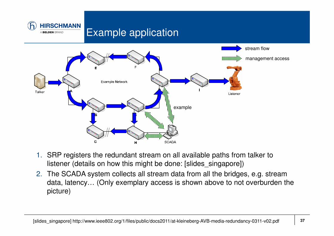
37
Example application
1. SRP registers the redundant stream on all available paths from talker to
listener (details on how this might be done: [slides_singapore])
2. The SCADA system collects all stream data from all the bridges, e.g. stream
data, latency… (Only exemplary access is shown above to not overburden the
picture)
stream flow
management access
example
[slides_singapore] http://www.ieee802.org/1/files/public/docs2011/at-kleineberg-AVB-media-redundancy-0311-v02.pdf

38
Example application
3. The SCADA system displays the topology, together with the stream flows and
the worst case latency (when more than one path is available)
4. From this information, a human operator through a network engineering tool,
an algorithm with application-specific knowledge, etc… can influence which
paths are to be configured for stream transmission
stream flow
management access
Human operator,
Algorithm, …
Delay=20
Delay=160
Delay=160 Delay=100
Delay=140
Delay=140
Delay=120
Delay=120
Delay=140
Delay= x � Worst
Case Delay
Abstract 20 delay /
bridge

39
Example application
5. In this case, a human operator decides to cut off the sub-ring through G and H
from this stream to reduce worst case latency, at the cost of some fault-
tolerance
6. In another use case (and with other requirements in the background), the
outcome of this decision could have been different!... E.g. when the additional
fault-tolerance outweighs the improvements to latency
stream flow
management access
Human operator,
Algorithm, …
Delay=20
Delay=120
Delay=120 Delay=100
Delay=100
Delay=80
Delay=100
Delay= x � Worst
Case Delay
Abstract 20 delay /
bridge