ref.: let/me 013/2018-19 to, central railway school
TRANSCRIPT

Ref.: LET/ME_013/2018-19
Date: 23/08/2018
To,
Central Railway School
Kalyan.
Sub : Demand Letter after completion of Commissioning of 5 KLD STP in Central Railway
School Kalyan.
Our Quotation Ref: MEC_009/Qtn R1/18-19, Dated 07/07/2018
Order Ref: CR/SCH/KYN/AL-18, Dated: 24/07/2018
Delevery Challan Ref: MA - 05/18-19 Dated: 10/08/2018
Dear Sir,
We refer to your order with reference no CR/SCH/KYN/AL-18, Dated: 24/07/2018 for
Installation & Commissioning of 5 KLD STP in Central Railway School Kalyan and as per
payment terms we had successfully completed the Commissioning of the above said STP system.
The commissioning report is attached for your reference. Sample of treated effluent of STP is
send for third party analysis which will be submitted latter.
We request you to release our second installment which is after commissioning ie Rs. 1,50,000/-
Thanking you and assuring you of our best services and attention at all times.
Thanking you,
For Manthan Enviro Consultancy
Authorized Signatory

August 23, 2018
Central Railway Secondary School and Junior College
Murbad Road
Kalyan
Subject: Commissioning Report of 5 KLD SEWAGE TREATMENT PLANT (STP)
Dear Sir,
In reference to the work order for 5 kld STP. Please find our completion report in respect with
Supply, Installation, Testing and Commissioning of ETP
Thanking you and assuring you of our best services and attention at all times.
For Manthan Enviro Consultancy
Authorized Signatory

1.0 Parameters considered for designing of STP
Parameter Unit Untreated Sewage Final treated water
Flow m3/day 5 5
pH ---- 6.5 - 8.5 6.5 - 8.5
Chemical Oxygen Demand mg/l 450 – 500 <250
Biological Oxygen Demand mg/l 350 – 450 < 30
Oil & Grease mg/l 30 – 50 <10
Total Suspended Solids mg/l 200-300 <100
Total Dissolved Solids mg/l < 2100 <2100
2.0 The sewage shall be treated in three stages:
2.1 Primary treatment:
Septic Tank overflow is received in Bar Screen where coarse screen is placed to prevent
inorganic coarse solids and debris from entering the tank and prevent clogging of pipes
and equipment. Solids like Plastic bags, bottles, Bottle Cap etc. are trapped and removed
manually. Over flow of this is goes to collection cum Equalization tan. In this tank
sewage is homogenized and mixed with pump recirculation line. This equalized sewage
is pump directly to Bio Reactor.
2.2 Secondary treatment:
The sewage is pumped from equalization tank to bio reactor with the help of centrifugal
pump. The bioreactor tank is provided with suspended biological mass. The mixing and
Oxygen transfer in the bio reactor is provided through fine bubble diffusers using air
blower. The MLVSS from the bio reactor overflows to the secondary settling tank. Here
the bio-solids settles down and gets separated from the sewage. The settled biomass will
be recycled back to the bio reactor for maintaining the MLVSS concentration. Excess
biomass shall be taken to Sludge dewatering unit.
2.3 Tertiary treatment:
This biologically treated sewage shall be pumped through a pressure sand filter (PSF)
for removing any fine solids escaping the secondary settling tank & then from Activated
Carbon filter for removal of any color and odor. A dose of NaOcl shall be given at the
intermediate tank for disinfection. The treated water shall be collected in the final
treated water tank.
Treated water from the final tank may be used for gardening or floor washing/ flushing
purpose or overflow to drainage / disposal system.
2.4 Ultra Violet System (UV)
After carbon filter UV is used as a final disinfecting system

3.0 Equipment Schedule for STP
Sr.
No. Description Capacity MOC Qty Installation Trial Run Commissioning
A) Civil (Client Scope)
1. Bar Screen
Chamber 0.3 m3 RCC
1
No Completed Completed Completed
2. Equalization
Tank 3 m3 RCC
1
No Completed Completed Completed
3. Shade for
Plant Suitable GI
1
No Completed Completed Completed
4. Equipment
& Pump
Foundations
Lot RCC 1
No Completed Completed Completed
B) Mechanical Equipment (Manthan Scope)
1. Bio Reactor
Feed Pump
1 m3/hr
@ 10 m
head
CI 1
No. Completed Completed Completed
2. Air blower
10
m3/hr
@ 0.3
KSC
CI 1
No Completed Completed Completed
3. Fine bubble
diffusers for
Bio Reactor
Suitable Silicon 2
Nos. Completed Completed Completed
4. Bio Reactor 3 m3 MS
Epoxy
1
No Completed Completed Completed
5. Settling
Tank 1.5 m3
MS
Epoxy
1
No Completed Completed Completed
6. Intermediate
Tank 100 L
MS
Epoxy
1
No Completed Completed Completed
7. PSF Feed
Pump
1 m3/hr
@ 10m
head
CI 1
No Completed Completed Completed
8. Pressure
Sand Filter (
PSF )
Suitable FRP 1
No Completed Completed Completed
9. Activated
Carbon
Filter ( ACF )
Suitable FRP 1
No Completed Completed Completed
10. NaOCl
Dosing Tank 50 L HDPE
1
No Completed Completed Completed
11. NaOCl
Dosing
Pump
0 – 5
LPH PP
1
No Completed Completed Completed
12. UV System Suitable SS 1
No Completed Completed Completed
13. Final
Treated
Water tank
250 L MS
Epoxy
1
No Completed Completed Completed

Sr.
No. Description Capacity MOC Qty Installation Trial Run Commissioning
C) Instrumentation (Manthan Scope)
1 Level switch Suitable PVC 2
Nos. Completed Completed Completed
D) Electrical (Manthan Scope)
Electrical Suitable Lot Completed Completed Completed
E) Piping (Manthan Scope)
Piping Suitable Lot Completed Completed Completed
There are no leakages in any of the piping.
Above all equipments related to STP is successfully installed and commissioned. Also sample is
taken whose report is attached.
Thanking you,
For Manthan Enviro Consultancy
Authorized Signatory

Standard Operating Manual
For
Sewage Treatment Plant
Of
Kalyan Railway School Murbard Road, Kalyan (W). Maharashtra 421301
Manthan Enviro Consultency
C – 2, Block No. 1001, Flamingo,
Neelkant Greens, Mulabaug Area.
Manpada, Thane (W) – 400607. Maharashtra, India.
Mob - 8850988302

INDEX
SR. NO. CONTENTS PAGE NO.
1. SECTION 1 : INTRODUCTION 1
2. SECTION 2 : GENERAL TREATMENT PROCESS 2 – 3
3. SECTION 3 :UNIT & EQUIPMENTS 4
4. SECTION 4 : STANDARD OPERATING PROCEDURE 5 – 9
5. SECTION 5 : GENERAL GUIDELINES FOR CORRECTIVE & PREVENTIVE ACTION
10 - 11
6. SECTION 6: MAINTENANCE 12

SECTION 1 - INTRODUCTION
Central Railway has set up a School at Murbad Road, Kalyan, Maharashtra-421301. Railway School has
installed a Full – Fledged Sewage Treatment Plant (STP) consisting of Primary, Secondary and Tertiary
system to cater to the treatment needs of the domestic Wastewater stream before discharging it for
gardening or for municipal drain.
Railway School had appointed Manthan Enviro Consultancy, Thane as a Detail Engineering Consultants
and Contractor for their Sewage Treatment Plant of capacity 5 M3/day.
Based on the availability of the area in the specified location; Manthan completed the detail engineering
and the Turnkey execution of the STP. Then, this STP was commissioned. During commissioning all the
teething problems were removed and STP operations were streamlined.
For the operators to run this STP without any problems detailed Operation Manual is prepared.
The Operation Manual has been organized as follows:-
•••• Section 1 - Introduction.
•••• Section 2 – General Treatment Process includes Design criteria, effluent characteristics and
anticipated characteristics of treated Wastewater, brief effluent treatment process which gives an
overall idea of proposed treatment scheme
•••• Section 3 – Units and Equipment includes Treatment plant with details units and equipment
•••• Section 4 - Standard Operating Procedures (SOP) for treatment plant. It describes each treatment
unit, procedures for every treatment unit / step, sludge handling operations etc. for easy operation
and effective results.
•••• Section 5 General Guidelines For Corrective & Preventive Action
•••• Section 6 : Maintenance

SECTION 2: GENERAL TREATMENT PROCESS
� Design Criteria
As sewage is discharged from wash rooms its COD, BOD values are much more than MPCB
standards. Hence, the treatment scheme selected is basically equalization, Biodegradation,
Secondary Settling and Tertiary Treatment. The unit is expected to generate 5 m3/day of sewage
wastewater which will be pumped to Bioreactor directly. The expected Raw Wastewater and
Treated Wastewater characteristics are listed below:
Parameter Unit Untreated Sewage Final treated water
Flow m3/day 5 5
pH ---- 6.5 - 8.5 6.5 - 8.5
Chemical Oxygen Demand mg/l 450 – 500 <250
Biological Oxygen Demand mg/l 350 – 450 < 30
Oil & Grease mg/l 30 – 50 <10
Total Suspended Solids mg/l 200-300 <100
Total Dissolved Solids mg/l < 2100 <2100

Treatment Scheme
1.0 The sewage shall be treated in three stages:
2.1 Primary treatment:
Septic Tank overflow is received in Bar Screen where coarse screen is placed to prevent
inorganic coarse solids and debris from entering the tank and prevent clogging of pipes and
equipment. Solids like Plastic bags, bottles, Bottle Cap etc. are trapped and removed
manually. Over flow of this is goes to collection cum Equalization tan. In this tank sewage is
homogenized and mixed with pump recirculation line. This equalized sewage is pump
directly to Bio Reactor.
2.2 Secondary treatment:
The sewage is pumped from equalization tank to bio reactor with the help of centrifugal
pump. The bioreactor tank is provided with suspended biological mass. The mixing and
Oxygen transfer in the bio reactor is provided through fine bubble diffusers using air
blower. The MLVSS from the bio reactor overflows to the secondary settling tank. Here the
bio-solids settles down and gets separated from the sewage. The settled biomass will be
recycled back to the bio reactor for maintaining the MLVSS concentration. Excess biomass
shall be taken to Sludge dewatering unit.
2.3 Tertiary treatment:
This biologically treated sewage shall be pumped through a pressure sand filter (PSF) for
removing any fine solids escaping the secondary settling tank & then from Activated Carbon
filter for removal of any color and odor. A dose of NaOcl shall be given at the intermediate
tank for disinfection. The treated water shall be collected in the final treated water tank.
Treated water from the final tank may be used for gardening or floor washing/ flushing
purpose or overflow to drainage / disposal system.
2.4 Ultra Violet System (UV)
After carbon filter UV is used as a final disinfecting system
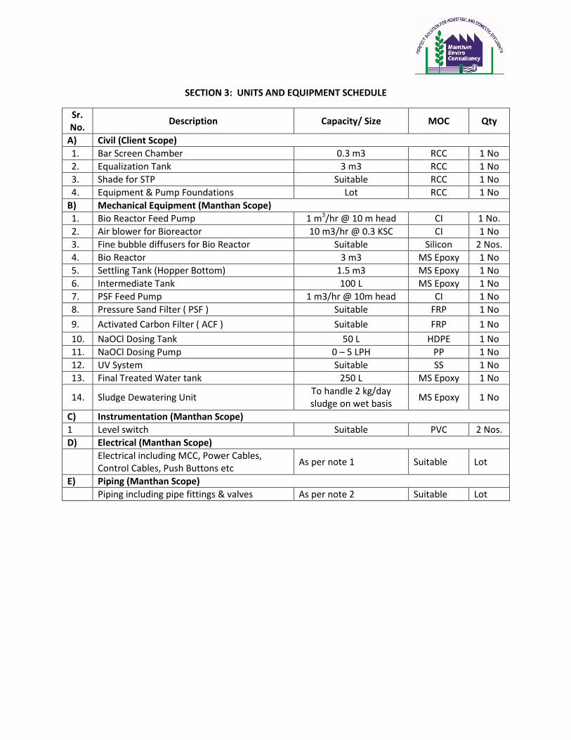
SECTION 3: UNITS AND EQUIPMENT SCHEDULE
Sr.
No. Description Capacity/ Size MOC Qty
A) Civil (Client Scope)
1. Bar Screen Chamber 0.3 m3 RCC 1 No
2. Equalization Tank 3 m3 RCC 1 No
3. Shade for STP Suitable RCC 1 No
4. Equipment & Pump Foundations Lot RCC 1 No
B) Mechanical Equipment (Manthan Scope)
1. Bio Reactor Feed Pump 1 m3/hr @ 10 m head CI 1 No.
2. Air blower for Bioreactor 10 m3/hr @ 0.3 KSC CI 1 No
3. Fine bubble diffusers for Bio Reactor Suitable Silicon 2 Nos.
4. Bio Reactor 3 m3 MS Epoxy 1 No
5. Settling Tank (Hopper Bottom) 1.5 m3 MS Epoxy 1 No
6. Intermediate Tank 100 L MS Epoxy 1 No
7. PSF Feed Pump 1 m3/hr @ 10m head CI 1 No
8. Pressure Sand Filter ( PSF ) Suitable FRP 1 No
9. Activated Carbon Filter ( ACF ) Suitable FRP 1 No
10. NaOCl Dosing Tank 50 L HDPE 1 No
11. NaOCl Dosing Pump 0 – 5 LPH PP 1 No
12. UV System Suitable SS 1 No
13. Final Treated Water tank 250 L MS Epoxy 1 No
14. Sludge Dewatering Unit To handle 2 kg/day
sludge on wet basis MS Epoxy 1 No
C) Instrumentation (Manthan Scope)
1 Level switch Suitable PVC 2 Nos.
D) Electrical (Manthan Scope)
Electrical including MCC, Power Cables,
Control Cables, Push Buttons etc As per note 1 Suitable Lot
E) Piping (Manthan Scope)
Piping including pipe fittings & valves As per note 2 Suitable Lot

SECTION 4: STANDARD OPERATING PROCEDURE
A) Effluent Collection Tank
1. Unit & Its General Arrangement :
This is a RCC tank of Capacity 3 m3. It is fitted with a level switch & Transfer Pumps.
2. Functions:
To collect the effluent coming from the school toilets and holding it for some time so as to
prevent shock loading.
3. SOP :
• The wastewater will come to the Collection Tank by gravity. When the water level reaches
a certain Point the Bio reactor feed pump will start automatically because of the Level
Switch LS.
• Keep the pump in the Auto Mode. Keep the recycle valve open or Close according to the
flow rate to be maintained.
• The pump will pump the wastewater to the Bio Reactor.
4. Operating Problem envisaged / its solutions :
For Pump:
1. Abnormal sounds or vibrations of Pump:-
The pump should run without vibration. The suction lift & head condition should not be
disturbed due to changes in the level of wastewater supply.
Check the liquid level in the tank and total head and adjust properly if necessary.
During long shutdowns, the delivery medium might change its condition, crystallization
or solidity therefore pump should be drained & flushed with suitable liquid (water) for
removing any chocking.
2. Improper working of Pump :-
• Excessive leakage through the stuffing box during early period of operation which stops
itself after the run in time. If necessary tighten the gland nuts. Avoid excessive
tightening. There should be a slight leak at the stuffing box to carry away the frictional
heat generated at the packing.
• Ensure if trouble is caused by the casing, shaft sealing, suction pipe, or foot valve.
Accordingly renew the gaskets on the casing, tighten the gland or renew the packing
ring, ensure the leak highness of suction pipe test valve, oil, seal.
• Dry running of pump should be avoided even for a few minutes.

B. BIOREACTOR:
1. Unit & Its General Arrangement :
It is MS Epoxy coated tank of capacity 3 m3.
2. Function:
The basic function of the bioreactor is to reduce the BOD of the effluent by aerobic respiration.
It has microorganisms which degrade the Biodegradable Organic matter in the wastewater thus
bringing about reduction in BOD and hence COD.
3. SOP:
Ensure steady flow of effluent in Bioreactor by checking the flow rate with the help of simple
Bucket System. The incoming flow rate should be around 1.0 m3. The wastewater will be
pumped into the Bioreactor by Effluent transfer.
• Ensure that the pH is between 7.5 – 8.0.
• Start the Air Pump AB – 101 A/B
• Always check that respective valve remain open.
• Check the bio sludge in the bioreactor with a help of a 100 ml measuring cylinder thrice
everyday (At least once in every Shift). For that take a random sample from the bioreactor in
the cylinder and allow the sludge to settle for 30 minutes. If the sludge volume is found to
exceed 40 % by volume in the measuring cylinder then drain the bio sludge to the sludge
drying unit using the air lift technology.
• Check the pH of the overflow of the Bioreactor. It should be between 7.0 – 7.5.
• Ensure the colour of the sludge is healthy brown.
• Add Urea, DAP and jaggery as required.
• Only one Air pump shall be operated at a time and other shall be used as standby.
• After every 8 hours run the standby blower and rest the working blower. Alternatively run
both the blowers.
• Keep Ready stock of the chemicals required i.e. Urea, DAP and Jaggery.

4. Operating Problem envisaged / its solutions:
For Air Pump: -
• Abnormal sounds, leaking of oil from packing joints & oil seal, clogging of safety valves.
• Ensure the pressure is according to duty conditions. It may be necessary to clean the
suction filter more frequently.
• Tighten the foundation bolts; pipe flange bolts etc. if loosened.
• It safety valves gets clogged up operate it manually to keep all the parts functional at the
time of need.
For Pumps: -
• Same as in B – Point 4 of A.
5. Malfunction for Pumps & Blowers:
� Excessive leakage through pipe joints.
� Improper flow at improper head i.e. overloading of pumps.
� If leakage through stuffing box is excess and tightening does not help, the packing should be
renewed because they might have lost their elasticity.
� After following SOP properly if any mechanical problem occurs it is recommended to
procure replacement of required parts.
C. SECONDARY SETTLING TANK:
1. Unit & Its General Arrangement:
It is rectangular MS Epoxy Painted tank of 1.5 m3. It has hopper at the bottom for the collection
and draining of the sludge.
2. Function :
Settling of Bio Sludge in the form of flocks.
3. SOP:
• The wastewater overflows to the Settling Tank from the bioreactor.
• The bio sludge will settle down by gravity settling.
• Keep the recirculation continuously ON.
• The flow rate of the recycle should be equal to the flow rate of the feed rate.
• To drain the excess sludge use Sludge drying unit.
• Ensure clear overflow of the effluent to the intermediate sump.
• pH should be neutral.

4. Operating Problem envisaged / its solutions:
a. Entrainment of the solids:
There may be entrainment of the solids from the settling tank. The launders of the settling
tank should be kept clean. The settling tank should be cleaned regularly (once in six months)
to remove any clogging in the hopper bottom nozzle.
b. Solids overflow to launders:
Check accumulation of sludge into Secondary Settling Tank.
c. Improper sludge delivery through sludge drains line.
This indicates choking of sludge in the line. For this cleaning of line should be done. Exert
pressure through air or by water so that chock can be removed.
D. Intermediate Tank
1. Unit & Its General Arrangement:
It consists of MS Epoxy tank 100 L capacity. It is provided with a level switch for safety measures.
2. Functions:
To hold the treated secondary overflow for pumping into the Pressure Sand Filter.
3. SOP:
� The clear overflow of the Secondary Settling Tank will overflow into the intermediate sump.
� Level Switch is been given a high level and low level limit. The PSF feed Pump will
automatically start pumping the water out of the tank or stop if the water level crosses the
high level or low level respectively.
� Keep the pump in auto mode and selector switch..
4. Operating Problem envisaged / its solutions:
a. Pump does not work properly
• Check coupling. If it is disconnected connect & align it.
• Check for power source it may be faulty.
• As mentioned in (B) – Point 4
• It may be calibration system error in level switch. If so evaluate & correct.

E. Bag Filter (BF)
1. Unit & Its General Arrangement:
It is a FRP Vessel.
2. Function:
To remove certain solids which have escaped through settling tank.
3. SOP:
� Level Switch is been given a high level and low level limit. The Pump will automatically start
pumping the water out of the intermediate tank or stop if the water level crosses the high
level or low level respectively.
� Keep the filter feed pump in auto mode and selector switch.
� Weekly bag should be cleaned.
4. Operating Problem envisaged / its solutions:
Cleaning should be done weekly.
F. Activated Carbon Filter (ACF)
1. Unit & Its General Arrangement:
It is a FRP Vessel.
2. Function:
To remove certain refractory organics, color, odor which are not bio degradable.
3. SOP:
� The carbon filter is in series with the Pressure Sand Filter PSF
� It should be cleaned every week.
� Carbon cartridge must be replaced every month
4. Operating Problem envisaged / its solutions:
Carbon should be changed regularly.
G. Final Treated Water Tank:
1. Unit & Its General Arrangement:
It is a MS Epoxy Tank of 250 L capacity.
2. Function:
To collect treated water and hold for discharge.
3. SOP:
Collect the treated water from the intermediate sump or PSF & ACF as mentioned.

SECTION 5: GENERAL GUIDELINES FOR CORRECTIVE & PREVENTIVE ACTION
1. BIOREACTOR
The biological process can be monitored by the appearance of the biomass (color, texture, etc.)
settling characteristics, volume, etc. Generally the color of the healthy biomass is yellowish
brown and while settling, it forms nice flocs of about 2 mm size. The structure of the settled
biomass is like small cotton balls, compound in a cylinder. For all practical purposes, the
concentration of organisms to be maintained is about 3500 mg/lit. and the healthy sludge at this
concentration will be occupy 20 - 30% volume after settling for 1 - 2 hr.
Generally two common problems are faced while operating activated sludge plants –
A. Rising Sludge
B. Bulking Sludge
A. Rising Sludge: The cause for this is gentrification in which the nitrites and nitrates in the
wastewater are converted to nitrogen gas. As nitrogen gas is formed in the sludge layer, it is
trapped in the sludge mass and if enough gas is formed, the sludge mass becomes buoyant
and rises to the surface. Rising sludge can be recognized by the presence of small gas
bubbles attached to the floating solids.
To overcome the rising sludge problem –
a. Increase the rate of return sludge from settling tank to bioreactor
b. Break the buoyant solids so that the gas bubbles escape and sludge mass goes down
B. Bulking Sludge - Bulk sludge has poor settling characteristics and a poor compatibility. Bulk
sludge can be differentiated from rising sludge by non presence of gas bubbles. Bulking of
sludge is caused by filamentous organisms of bound water in the bacterial cells, which swell
the cells and reduce their density. Bulking of sludge can be caused by –
i. Improper oxygen supply
ii. Sudden variations in wastewater characteristics as flow and strength, pH, temperature,
nutrient contents, etc.
iii. Improper recycle of settled sludge - In case of bulking sludge, check : waste water
characteristics and BOD loading , dissolved contents in the aeration tank.

iv. Clarifier functioning and proper return sludge pumping rate.
In case of bulking sludge –
a. Check the surface aerator immersion & operation
b. Check for any shock loading & reduce the BOD
c. Check the MLSS and waste the excess biomass
d. Check the return sludge pumping rate
e. Add H2O2 in the aeration tank if required to provide excess oxygen
The following table gives in short the monitoring of the biomass
CHARACTERISTICS OF BIOMASS INDICATIVE OF REMEDY
Yellowish brown color- good healthy sludge settling characteristics, forms nice flocs, while
settling volume is about 20 - 30 %
Pale Yellow or off white color - Over oxidation , less % settling
1) Check the feed BOD loading in
kg/day which may be less
2) Check immersion of surface
aerator
3) Operate the surface aerator
intermittently.
Gelatinous or sticky biomass -
filamentous growth observed
while settling
1) Shock Loading
2) Improper functioning of
aerator
1) Accumulate the feed wastewater
at alternative arrangement and stop
feeding to the bio reactor
2) Keep the surface aerator ad return
sludge pump ‘ON’
3) Check functioning of aerator and
return sludge pump.
4) Add H2O2 & Bleaching powder (if
required)in small quantity
Black colour , foul smell,
smelling sludge
1) Improper mixing
2) Shock Loading
1) Check the surface aerator
performance and immersion
2) Observe that all the settled sludge
is getting recycled to bio-reactor
3) Check the characteristics of the
inlet wastewater and avoid
overloading
4) Stop feeding reactor temporarily

SECTION 6: MAINTENANCE
A) Mechanical:
1. Check the Oil in Oil Cup of every pump every day.
2. Fill the grease in every pump and motor grease cup or Bearing every 1 month (30 days)
3. Motor or Pump alignment to check every 1-month for any misalignment to rectify
immediately.
4. If the pump is gland stuffing box type, gland should be changed every 15 days with proper
MOC of gland (Graphite, Asbestos or Teflon etc.)
5. Pump should be kept horizontally leveled and coupling alignment should be carried out before
startup of the pump.
6. Check pump and motor for free movement check grease in the grease cup provided on pump
casing.
B) Electrical:
1. Check the free movement of the push buttons (both Green and Red) every 15 days. Replace
the springs or buttons if jam / not operating.
2. Check the overload relays are operating correctly at +1 Amp than Set value (as per HP / KW
of the motor full load current and actual drawing current of the particular motor)