ref43 +2.5 v low power precision voltage reference data ... · +2.5 v low power precision voltage...
TRANSCRIPT
REV. D
Information furnished by Analog Devices is believed to be accurate andreliable. However, no responsibility is assumed by Analog Devices for itsuse, nor for any infringements of patents or other rights of third parties thatmay result from its use. No license is granted by implication or otherwiseunder any patent or patent rights of Analog Devices. Trademarks andregistered trademarks are the property of their respective owners.
One Technology Way, P.O. Box 9106, Norwood, MA 02062-9106, U.S.A.
Tel: 781/329-4700 www.analog.com
Fax: 781/326-8703 © 2004 Analog Devices, Inc. All rights reserved.
REF43
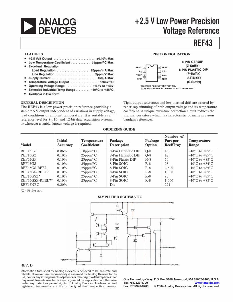
+2.5 V Low Power PrecisionVoltage Reference
FEATURES PIN CONFIGURATION
GENERAL DESCRIPTIONThe REF43 is a low power precision reference providing astable 2.5 V output independent of variations in supply voltage,load conditions or ambient temperature. It is suitable as areference level for 8-, 10- and 12-bit data acquisition systems,or wherever a stable, known voltage is required.
SIMPLIFIED SCHEMATIC
ORDERING GUIDE
Number ofInitial Temperature Package Package Part per Temperature
Model Accuracy Coefficient Description Option Reel/Tray Range
REF43FZ 0.06% 10ppm/∞C 8-Pin Hermetic DIP Q-8 48 –40∞C to +85∞CREF43GZ 0.10% 25ppm/∞C 8-Pin Hermetic DIP Q-8 48 –40∞C to +85∞CREF43GP 0.10% 25ppm/∞C 8-Pin Plastic DIP N-8 50 –40∞C to +85∞CREF43GS 0.10% 25ppm/∞C 8-Pin SOIC R-8 98 –40∞C to +85∞CREF43GS-REEL 0.10% 25ppm/∞C 8-Pin SOIC R-8 2,500 –40∞C to +85∞CREF43GS-REEL7 0.10% 25ppm/∞C 8-Pin SOIC R-8 1,000 –40∞C to +85∞CREF43GSZ* 0.10% 25ppm/∞C 8-Pin SOIC R-8 98 –40∞C to +85∞CREF43GSZ-REEL7* 0.10% 25ppm/∞C 8-Pin SOIC R-8 1,000 –40∞C to +85∞CREF43NBC 0.20% Die 221
*Z = Pb-free part.
Tight output tolerances and low thermal drift are assured byzener-zap trimming of both output voltage and its temperaturecoefficient. A unique curvature correction circuit reduces thethermal curvature which is characteristic of many previousbandgap references.
TEMP
VIN
VOUT
TRIM
GROUND
REV. D–2–
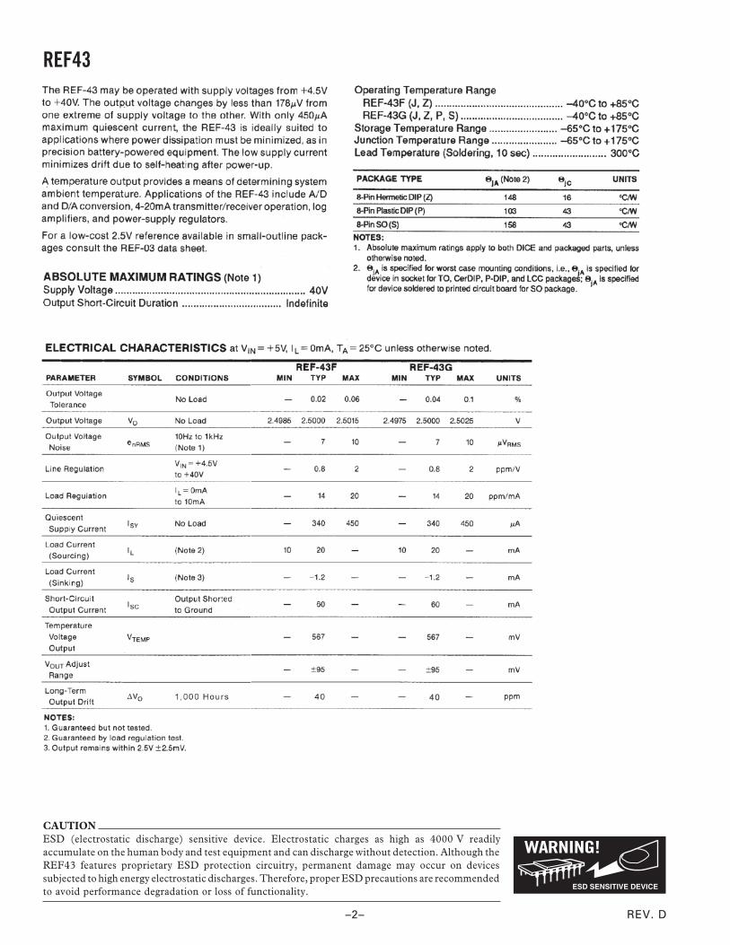
REF43
CAUTIONESD (electrostatic discharge) sensitive device. Electrostatic charges as high as 4000 V readilyaccumulate on the human body and test equipment and can discharge without detection. Although theREF43 features proprietary ESD protection circuitry, permanent damage may occur on devicessubjected to high energy electrostatic discharges. Therefore, proper ESD precautions are recommendedto avoid performance degradation or loss of functionality.
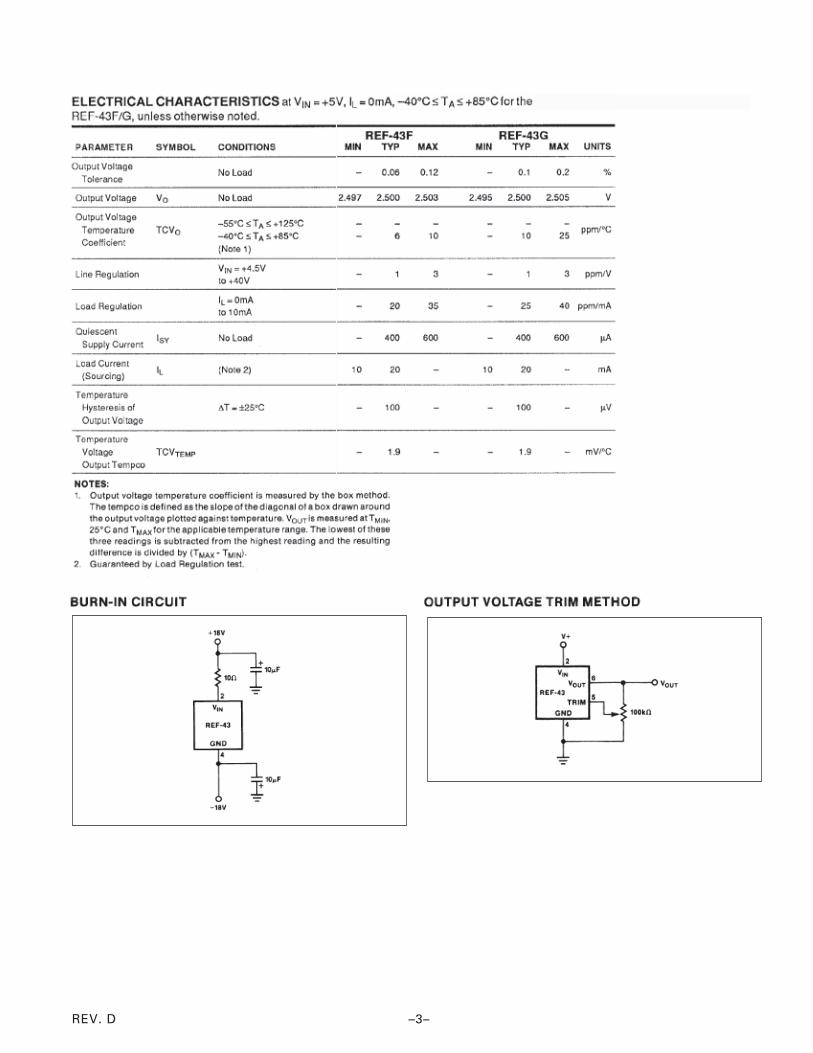
REV. D –3–
REV. D–4–
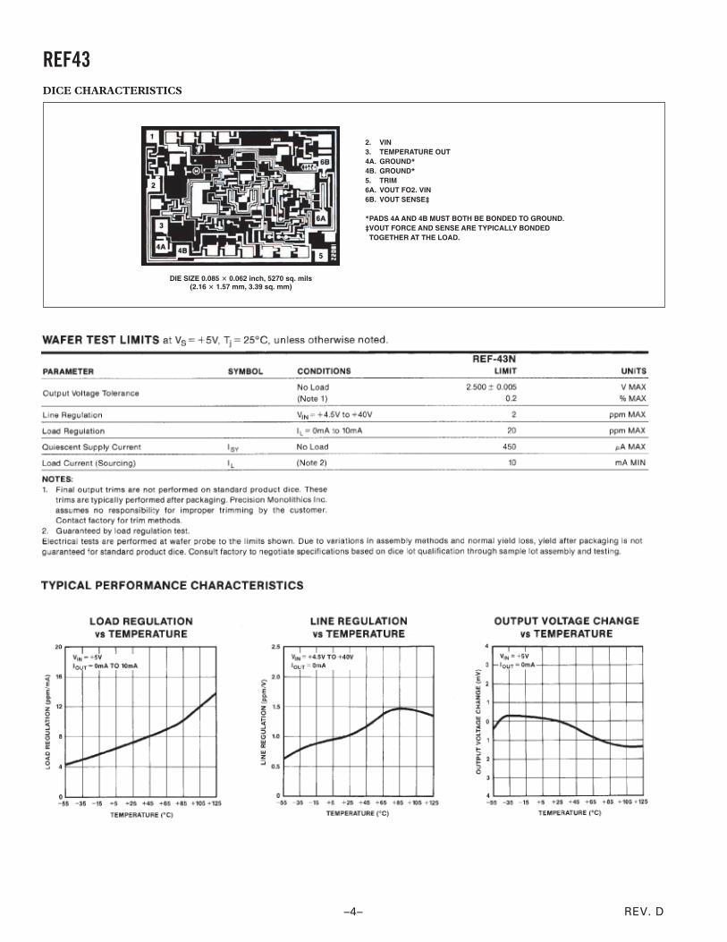
REF43DICE CHARACTERISTICS
DIE SIZE 0.085 � 0.062 inch, 5270 sq. mils(2.16 � 1.57 mm, 3.39 sq. mm)
2.3.4A.4B.5.6A.6B.
*PADS 4A AND 4B MUST BOTH BE BONDED TO GROUND.‡VOUT FORCE AND SENSE ARE TYPICALLY BONDED TOGETHER AT THE LOAD.
VINTEMPERATURE OUTGROUND*
GROUND*
TRIMVOUT FO2. VINVOUT SENSE‡
REV. D
REF43
–5–
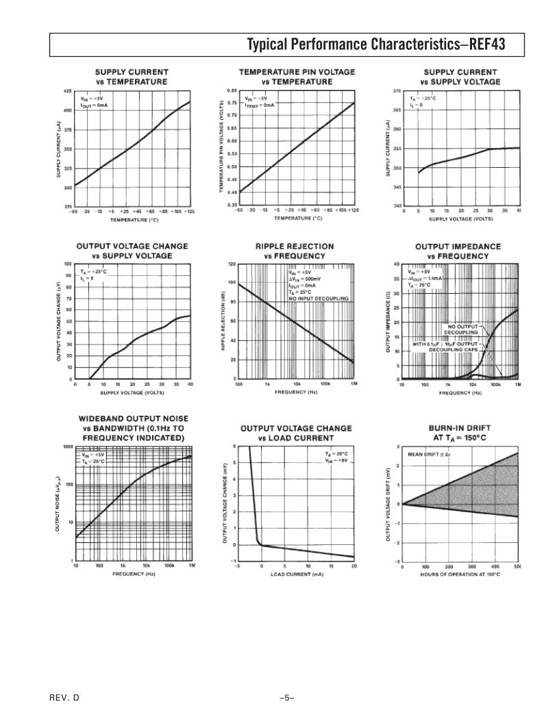
Typical Performance Characteristics–
REV. D–6–
REF43
REV. D
REF43
–7–

REV. D–8–
REF43
*OP AMP IS OP43 IF HIGHER SPEED AND FASTER SETTING IS REQUIRED.OP97 IF LOWER SPEED AND HIGHER LINEARITY IS REQUIRED.
REV. D
REF43
–9–
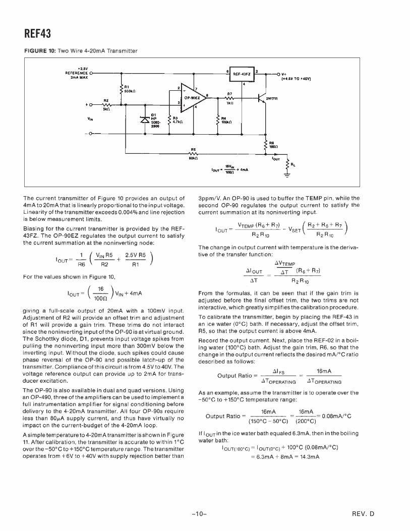
REV. D–10–
REF43
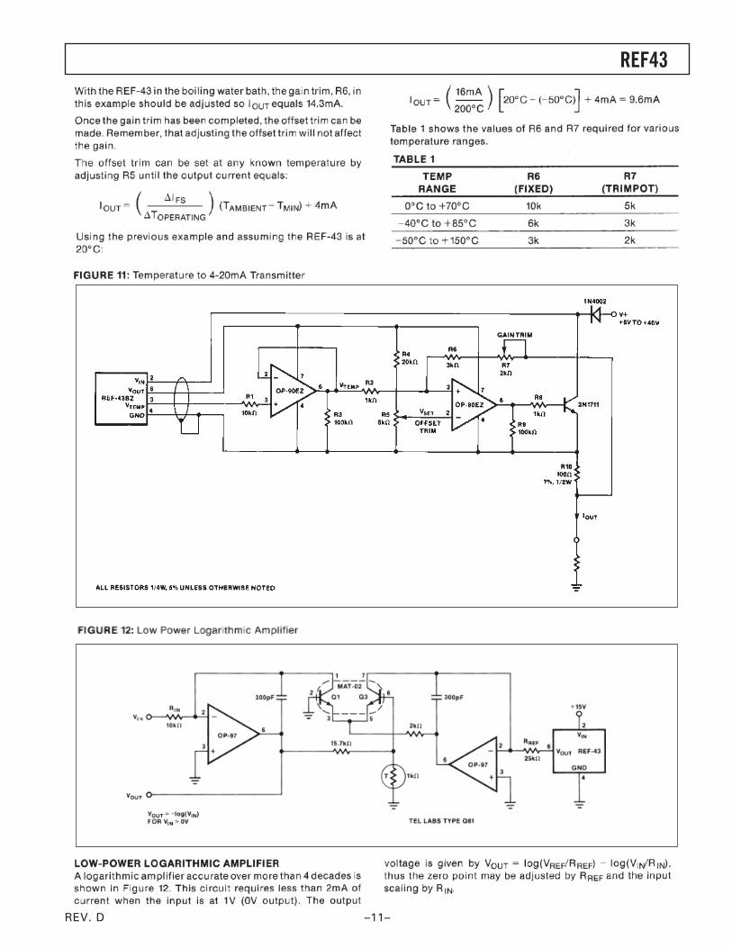
REV. D
REF43
–11–
REV. D
C00
374–
0–8/
04(D
)
–12–
REF43
Revision HistoryLocation Page
8/04—Data Sheet Changed from REV. C to REV. D.
Edits to FEATURES . . . . . . . . . . . . . . . . . . . . . . . . . . . . . . . . . . . . . . . . . . . . . . . . . . . . . . . . . . . . . . . . . . . . . . . . . . . . . . . . . . . . . 1
Changes to PIN CONFIGURATION . . . . . . . . . . . . . . . . . . . . . . . . . . . . . . . . . . . . . . . . . . . . . . . . . . . . . . . . . . . . . . . . . . . . . . . . 1
Changes to ORDERING GUIDE . . . . . . . . . . . . . . . . . . . . . . . . . . . . . . . . . . . . . . . . . . . . . . . . . . . . . . . . . . . . . . . . . . . . . . . . . . . 1
Changes to ABSOLUTE MAXIMUM RATINGS . . . . . . . . . . . . . . . . . . . . . . . . . . . . . . . . . . . . . . . . . . . . . . . . . . . . . . . . . . . . . . 2
Changes to PACKAGE TYPE . . . . . . . . . . . . . . . . . . . . . . . . . . . . . . . . . . . . . . . . . . . . . . . . . . . . . . . . . . . . . . . . . . . . . . . . . . . . . 2
Changes to ELECTRICAL CHARACTERISTICS . . . . . . . . . . . . . . . . . . . . . . . . . . . . . . . . . . . . . . . . . . . . . . . . . . . . . . . . . . . . . 2
Delected PACKAGE TYPE . . . . . . . . . . . . . . . . . . . . . . . . . . . . . . . . . . . . . . . . . . . . . . . . . . . . . . . . . . . . . . . . . . . . . . . . . . . . . . . 7
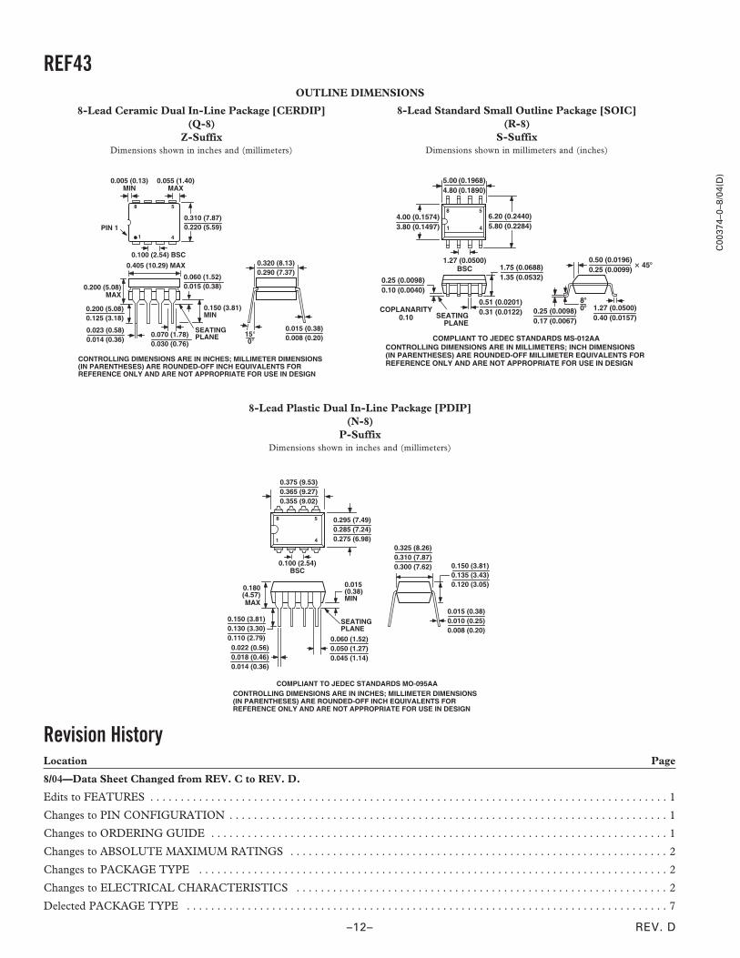
8-Lead Plastic Dual In-Line Package [PDIP](N-8)
P-SuffixDimensions shown in inches and (millimeters)
SEATINGPLANE
0.180(4.57)MAX
0.150 (3.81)0.130 (3.30)0.110 (2.79) 0.060 (1.52)
0.050 (1.27)0.045 (1.14)
8
1 4
5 0.295 (7.49)0.285 (7.24)0.275 (6.98)
0.100 (2.54)BSC
0.375 (9.53)0.365 (9.27)0.355 (9.02)
0.150 (3.81)0.135 (3.43)0.120 (3.05)
0.015 (0.38)0.010 (0.25)0.008 (0.20)
0.325 (8.26)0.310 (7.87)0.300 (7.62)
0.022 (0.56)0.018 (0.46)0.014 (0.36)
CONTROLLING DIMENSIONS ARE IN INCHES; MILLIMETER DIMENSIONS(IN PARENTHESES) ARE ROUNDED-OFF INCH EQUIVALENTS FORREFERENCE ONLY AND ARE NOT APPROPRIATE FOR USE IN DESIGN
COMPLIANT TO JEDEC STANDARDS MO-095AA
0.015(0.38)MIN
OUTLINE DIMENSIONS
8-Lead Standard Small Outline Package [SOIC](R-8)
S-SuffixDimensions shown in millimeters and (inches)
0.25 (0.0098)0.17 (0.0067)
1.27 (0.0500)0.40 (0.0157)
0.50 (0.0196)0.25 (0.0099)
� 45�
8�0�
1.75 (0.0688)1.35 (0.0532)
SEATINGPLANE
0.25 (0.0098)0.10 (0.0040)
8 5
41
5.00 (0.1968)4.80 (0.1890)
4.00 (0.1574)3.80 (0.1497)
1.27 (0.0500)BSC
6.20 (0.2440)5.80 (0.2284)
0.51 (0.0201)0.31 (0.0122)COPLANARITY
0.10
CONTROLLING DIMENSIONS ARE IN MILLIMETERS; INCH DIMENSIONS(IN PARENTHESES) ARE ROUNDED-OFF MILLIMETER EQUIVALENTS FORREFERENCE ONLY AND ARE NOT APPROPRIATE FOR USE IN DESIGN
COMPLIANT TO JEDEC STANDARDS MS-012AA
8-Lead Ceramic Dual In-Line Package [CERDIP](Q-8)
Z-SuffixDimensions shown in inches and (millimeters)
1 4
8 5
0.310 (7.87)0.220 (5.59)PIN 1
0.005 (0.13)MIN
0.055 (1.40)MAX
0.100 (2.54) BSC
15 0
0.320 (8.13)0.290 (7.37)
0.015 (0.38)0.008 (0.20)
SEATINGPLANE
0.200 (5.08)MAX
0.405 (10.29) MAX
0.150 (3.81)MIN
0.200 (5.08)0.125 (3.18)
0.023 (0.58)0.014 (0.36)
0.070 (1.78)0.030 (0.76)
0.060 (1.52)0.015 (0.38)
CONTROLLING DIMENSIONS ARE IN INCHES; MILLIMETER DIMENSIONS(IN PARENTHESES) ARE ROUNDED-OFF INCH EQUIVALENTS FORREFERENCE ONLY AND ARE NOT APPROPRIATE FOR USE IN DESIGN