refactoring-based requirements refinement towards … · refactoring-based requirements re nement...
TRANSCRIPT
Refactoring-based Requirements Refinement
Towards Design
by
Wendy WenQian Liu
A thesis submitted in conformity with the requirementsfor the degree of Doctor of Philosophy
Graduate Department of Computer ScienceUniversity of Toronto
Copyright c© 2009 by Wendy WenQian Liu

Abstract
Refactoring-based Requirements Refinement Towards Design
Wendy WenQian Liu
Doctor of Philosophy
Graduate Department of Computer Science
University of Toronto
2009
Building systems that satisfy the given requirements is a main goal of software engineer-
ing. The success of this process relies largely on the presence of an adequate architectural
design. Traditional paradigms deal with requirements separately from design. Our empir-
ical studies show that crossing the boundary between requirements and design is difficult,
existing tools and methods for bridging the gap inadequate, and that software architects
rely heavily on experience, prior solutions, and creativity.
Current approaches in moving from requirements to design follow two schools. One
is architecture-centric, focused on providing assistance to architects in reuse. The other
is requirements-centric, and tends to extend established development frameworks and
employ mappings to transition from requirements to architecture. Jackson indicates that
clear understanding of requirements (the problem) is crucial to building useful systems,
and that to evolve successfully, their design must reflect problem structure. Taylor et
al. argue that design is the central activity in connecting requirements and architecture.
Nonetheless, existing approaches either overlook underlying structure of requirements or
design considerations.
This dissertation presents a novel theory enabling requirements structuring and de-
sign analysis through requirements refinement and refactoring. The theory introduces a
refinement process model operating on four abstraction levels, and a set of refactoring
ii

operators and algorithms. The method works in small, well-guided steps with visible
progress.
The theory provides a basis for designers to analyze and simplify requirement de-
scriptions, remove redundancy, uncover dependencies, extract lower-level requirements,
incorporate design concerns, and produce a system decomposition reflecting the under-
lying problem structure. A design built on top of this decomposition is better suited for
evolution than one created without explicit structural analysis.
The theory is validated on an industrial-sized project, wherein a suitable system
decomposition is produced and a comparison made to a conventionally-devised solution.
Examples demonstrate that the theory handles changes incrementally. It is explained
how the theory addresses the existing challenges in going from requirements to design and
supports fundamental software engineering principles. The method is assessed against
common validation criteria. The approach is compared with prominent related work.
iii

To my family
iv

Acknowledgements
It has been a long journey, and I could not have completed it all on my own. I have many
people to thank, who have accompanied me, enlightened me, supported me, encouraged
me, challenged me, and helped me. To all of them, I am deeply grateful.
Foremost, I thank my thesis supervisor, Steve Easterbrook, for his advice, input,
encouragement, and support over the years of my graduate study. I am grateful to my
thesis committee — Eric Yu, John Mylopoulos, and Kelly Lyons, and external examiner,
Julio Leite, for their suggestions and input. I owe a special thank-you to Eric Hehner for
his involvement and influence upon my research.
I am grateful to have had the opportunity to collaborate with Dewayne Perry and
his team at University of Texas at Austin. He always welcomes discussions and is very
generous with his time and feedback. I thank Sharon Lymer and Mike Starkey for
presenting challenging real-world problems and collaborating on research. I thank Marin
Litoiu for guiding me during my time at IBM CAS. I am grateful to Martin Glinz for an
enlightening discussion at a key point in my research. I thank all the participants of my
empirical studies.
I am indebted to my friends and colleagues, Borys Bradel and Jie Ren, for critiquing
early drafts of my work and offering ideas and encouragement.
I wish to thank my many friends for providing me with moral support. Leslie Wang
cheers me up when I feel down. Tao Zheng has made my fellowship-stays delightful.
Arbi Ghazarian never fails to strike up a good conversation. Yiqiao Wang offers her
empathy for the ups and downs of student life. Edmund Fok persuades me to attend
bridge tournaments as a distraction and to challenge my mind in an entirely different
way. I wish to thank Stuart Thompson for giving me the courage to leave the industry
and take a step into the unknown.
v

To the many people who have influenced me and my work, and are not mentioned by
name, I thank you.
I would not be who I am or be able to complete this difficult task without the influ-
ence and education I received from my family. I thank my father, David, for his strong
influence in reaching higher achievements, and my mother, Ling, for provoking my philo-
sophical curiosity. I thank my brother, Harry, for reminding me to be a better person,
and my grandmother, Guiying, for her loving care and nurturing.
Finally, I wish to express my deepest gratitude to my husband, Peter, for his love,
kindness, patience, encouragement, emotional support, mentoring, research input, and
walking with me through the entire journey.
vi

Contents
Abstract ii
Acknowledgements v
1 Introduction 1
1.1 Background . . . . . . . . . . . . . . . . . . . . . . . . . . . . . . . . . . 2
1.1.1 From Software Requirements to Architecture . . . . . . . . . . . . 3
1.1.2 Software Engineering Principles . . . . . . . . . . . . . . . . . . . 9
1.2 Research Approach . . . . . . . . . . . . . . . . . . . . . . . . . . . . . . 11
1.3 Contributions . . . . . . . . . . . . . . . . . . . . . . . . . . . . . . . . . 13
1.4 Dissertation Outline . . . . . . . . . . . . . . . . . . . . . . . . . . . . . 15
2 Requirements Decomposition, Refinement & Refactoring 17
2.1 Foundation of Requirements Engineering . . . . . . . . . . . . . . . . . . 18
2.2 Requirements Decomposition . . . . . . . . . . . . . . . . . . . . . . . . 21
2.2.1 Requirements Partition . . . . . . . . . . . . . . . . . . . . . . . . 22
2.2.2 Problem Decomposition . . . . . . . . . . . . . . . . . . . . . . . 24
2.2.3 Goal Decomposition . . . . . . . . . . . . . . . . . . . . . . . . . 27
2.2.4 Formal Methods . . . . . . . . . . . . . . . . . . . . . . . . . . . . 29
2.2.5 Viewpoints . . . . . . . . . . . . . . . . . . . . . . . . . . . . . . 32
vii

2.2.6 Traceability . . . . . . . . . . . . . . . . . . . . . . . . . . . . . . 34
2.3 Requirements Refinement . . . . . . . . . . . . . . . . . . . . . . . . . . 36
2.3.1 Goal Refinement . . . . . . . . . . . . . . . . . . . . . . . . . . . 37
2.3.2 Refinement Through Non-functional Decomposition and Conflict
Resolution . . . . . . . . . . . . . . . . . . . . . . . . . . . . . . . 40
2.3.3 Inquiry Cycle Model . . . . . . . . . . . . . . . . . . . . . . . . . 44
2.3.4 Process-oriented Refinement . . . . . . . . . . . . . . . . . . . . . 46
2.4 Refactoring in Software Engineering . . . . . . . . . . . . . . . . . . . . . 47
2.4.1 Software Refactoring . . . . . . . . . . . . . . . . . . . . . . . . . 47
2.4.2 Program Refactoring . . . . . . . . . . . . . . . . . . . . . . . . . 49
2.4.3 Design Refactoring . . . . . . . . . . . . . . . . . . . . . . . . . . 50
2.5 Critical Analysis . . . . . . . . . . . . . . . . . . . . . . . . . . . . . . . 52
2.5.1 On Decomposition Criteria . . . . . . . . . . . . . . . . . . . . . . 52
2.5.2 On Refinement and Design . . . . . . . . . . . . . . . . . . . . . . 53
2.5.3 On the Role of Refactoring . . . . . . . . . . . . . . . . . . . . . . 53
2.5.4 Concluding Remarks . . . . . . . . . . . . . . . . . . . . . . . . . 56
2.6 Summary . . . . . . . . . . . . . . . . . . . . . . . . . . . . . . . . . . . 58
3 Empirical Evidence 60
3.1 Business Scenario Framework . . . . . . . . . . . . . . . . . . . . . . . . 60
3.1.1 Overview of Business Scenario Framework (BSF) . . . . . . . . . 61
3.1.2 Lessons Learned . . . . . . . . . . . . . . . . . . . . . . . . . . . . 62
3.2 On the Meaning of Software Architecture . . . . . . . . . . . . . . . . . . 68
3.2.1 Study Design . . . . . . . . . . . . . . . . . . . . . . . . . . . . . 69
3.2.2 Data Digest . . . . . . . . . . . . . . . . . . . . . . . . . . . . . . 70
3.2.3 Evidence Collected in Going from Requirements to Architecture . 71
viii

3.3 Discussions . . . . . . . . . . . . . . . . . . . . . . . . . . . . . . . . . . 73
3.4 Summary . . . . . . . . . . . . . . . . . . . . . . . . . . . . . . . . . . . 75
4 A Simple Requirements Refactoring Example 76
4.1 A Simple Requirements Refactoring Method . . . . . . . . . . . . . . . . 77
4.1.1 Definitions . . . . . . . . . . . . . . . . . . . . . . . . . . . . . . . 77
4.1.2 Method . . . . . . . . . . . . . . . . . . . . . . . . . . . . . . . . 81
4.1.3 The KWIC Example . . . . . . . . . . . . . . . . . . . . . . . . . 82
4.2 Insight to Requirements Refactoring . . . . . . . . . . . . . . . . . . . . . 96
4.2.1 Meaning of Requirements Refactoring . . . . . . . . . . . . . . . . 96
4.2.2 Role of Requirements Refactoring . . . . . . . . . . . . . . . . . . 97
4.3 Summary . . . . . . . . . . . . . . . . . . . . . . . . . . . . . . . . . . . 98
5 Theory of Refactoring-based Requirements Refinement 99
5.1 Theory Constructs and Goal . . . . . . . . . . . . . . . . . . . . . . . . . 99
5.1.1 Principal Concepts and Relationship . . . . . . . . . . . . . . . . 100
5.1.2 Goal of the Theory . . . . . . . . . . . . . . . . . . . . . . . . . . 102
5.2 Refinement Model (Framework) . . . . . . . . . . . . . . . . . . . . . . . 103
5.2.1 Designer versus User Stance . . . . . . . . . . . . . . . . . . . . . 106
5.2.2 Requirements Abstraction Levels and Refinement Phases . . . . . 106
5.3 Refactoring Method . . . . . . . . . . . . . . . . . . . . . . . . . . . . . . 109
5.3.1 Definitions . . . . . . . . . . . . . . . . . . . . . . . . . . . . . . . 110
5.3.2 Refactoring Operators . . . . . . . . . . . . . . . . . . . . . . . . 115
5.3.2.1 Properties of Operator Composition . . . . . . . . . . . 123
5.3.3 Refactoring Algorithms . . . . . . . . . . . . . . . . . . . . . . . . 128
5.3.3.1 Problem-level Refactoring . . . . . . . . . . . . . . . . . 128
5.3.3.2 Domain-level Refactoring . . . . . . . . . . . . . . . . . 134
ix

5.3.3.3 Product-level Refactoring . . . . . . . . . . . . . . . . . 138
5.3.3.4 Component-level Refactoring . . . . . . . . . . . . . . . 140
5.3.4 Discussions . . . . . . . . . . . . . . . . . . . . . . . . . . . . . . 142
5.3.4.1 Intent Preservation and Human Factors . . . . . . . . . 142
5.3.4.2 Non-Functional Requirements . . . . . . . . . . . . . . . 146
5.4 Summary . . . . . . . . . . . . . . . . . . . . . . . . . . . . . . . . . . . 148
6 Case Study 149
6.1 Applying Refinement and Refactoring . . . . . . . . . . . . . . . . . . . . 149
6.1.1 Problem-level Refactoring . . . . . . . . . . . . . . . . . . . . . . 150
6.1.2 Domain-level Refactoring . . . . . . . . . . . . . . . . . . . . . . . 158
6.1.3 Product-level Refactoring . . . . . . . . . . . . . . . . . . . . . . 172
6.1.4 Component-level Refactoring . . . . . . . . . . . . . . . . . . . . . 173
6.2 Handling Changes in Requirements . . . . . . . . . . . . . . . . . . . . . 176
6.2.1 New Requirement . . . . . . . . . . . . . . . . . . . . . . . . . . . 178
6.2.2 Modified Requirement . . . . . . . . . . . . . . . . . . . . . . . . 179
6.2.3 Deleted Requirement . . . . . . . . . . . . . . . . . . . . . . . . . 181
6.3 Comparison to an Industry Solution . . . . . . . . . . . . . . . . . . . . . 182
6.3.1 Comparison at the Framework Level . . . . . . . . . . . . . . . . 183
6.3.2 Comparison at the Artifact Level . . . . . . . . . . . . . . . . . . 184
6.4 Summary . . . . . . . . . . . . . . . . . . . . . . . . . . . . . . . . . . . 186
7 Evaluation 189
7.1 Validation via Critical Analysis . . . . . . . . . . . . . . . . . . . . . . . 189
7.1.1 Method Validation . . . . . . . . . . . . . . . . . . . . . . . . . . 190
7.1.2 Challenges Addressed . . . . . . . . . . . . . . . . . . . . . . . . . 193
7.1.3 Principles Supported . . . . . . . . . . . . . . . . . . . . . . . . . 196
x

7.1.4 Limitations . . . . . . . . . . . . . . . . . . . . . . . . . . . . . . 197
7.2 Comparison to Related Work . . . . . . . . . . . . . . . . . . . . . . . . 199
7.2.1 Feature-driven Requirements Dependency Analysis . . . . . . . . 199
7.2.2 Goal-oriented Architecture Derivation . . . . . . . . . . . . . . . . 202
7.2.3 Tropos . . . . . . . . . . . . . . . . . . . . . . . . . . . . . . . . . 204
7.2.4 Architectural Frames . . . . . . . . . . . . . . . . . . . . . . . . . 206
7.2.5 Comparisons . . . . . . . . . . . . . . . . . . . . . . . . . . . . . 207
7.3 Summary . . . . . . . . . . . . . . . . . . . . . . . . . . . . . . . . . . . 209
8 Conclusions 210
8.1 Research Contributions . . . . . . . . . . . . . . . . . . . . . . . . . . . . 210
8.2 Further Research . . . . . . . . . . . . . . . . . . . . . . . . . . . . . . . 212
Bibliography 213
A Questionnaire – On the Meaning of Software Architecture 229
A.1 Problem Domain . . . . . . . . . . . . . . . . . . . . . . . . . . . . . . . 229
A.2 Overview of Software Architecture . . . . . . . . . . . . . . . . . . . . . . 230
A.3 Requirements and Architecture . . . . . . . . . . . . . . . . . . . . . . . 232
A.4 Relating to Evolution . . . . . . . . . . . . . . . . . . . . . . . . . . . . . 234
A.5 Professional Background . . . . . . . . . . . . . . . . . . . . . . . . . . . 235
B Supplementary Data on Employee Workplace 237
B.1 Business Needs . . . . . . . . . . . . . . . . . . . . . . . . . . . . . . . . 237
B.2 High-level Features/Components in BSF . . . . . . . . . . . . . . . . . . 246
xi

List of Tables
2.1 A simple example of the NFD matrix . . . . . . . . . . . . . . . . . . . . 43
5.1 Theory of refactoring-based requirements refinement . . . . . . . . . . . . 104
6.1 Summary of initial business needs . . . . . . . . . . . . . . . . . . . . . . 151
6.2 Business need, P1 . . . . . . . . . . . . . . . . . . . . . . . . . . . . . . . 151
6.3 Initial problem partition . . . . . . . . . . . . . . . . . . . . . . . . . . . 153
6.4 Results of syntactic refactoring . . . . . . . . . . . . . . . . . . . . . . . 153
6.5 Problem descriptions after syntactic refactoring . . . . . . . . . . . . . . 155
6.6 Results of intra-segment refactoring . . . . . . . . . . . . . . . . . . . . . 155
6.7 Results of inter-segment refactoring . . . . . . . . . . . . . . . . . . . . . 156
6.8 The problem decomposition . . . . . . . . . . . . . . . . . . . . . . . . . 156
6.9 Problem-level refined business needs . . . . . . . . . . . . . . . . . . . . . 157
6.10 Segments of the solution decomposition . . . . . . . . . . . . . . . . . . . 168
6.11 Domain-level refactored business needs . . . . . . . . . . . . . . . . . . . 169
6.12 Summary of scenarios . . . . . . . . . . . . . . . . . . . . . . . . . . . . . 169
6.13 Use cases derived from scenarios . . . . . . . . . . . . . . . . . . . . . . . 170
6.14 Examples of derived use cases . . . . . . . . . . . . . . . . . . . . . . . . 174
6.15 Use cases mapped to components . . . . . . . . . . . . . . . . . . . . . . 175
6.16 Use case dependencies . . . . . . . . . . . . . . . . . . . . . . . . . . . . 176
xii

6.17 All extracted use cases . . . . . . . . . . . . . . . . . . . . . . . . . . . . 177
6.18 Changes to the candidate design with a new requirement added . . . . . 179
6.19 Changes to the decomposition when a requirement is modified . . . . . . 181
6.20 Changes in problem descriptions when a requirement is modified . . . . . 181
6.21 Changes to the decomposition when a requirement is deleted . . . . . . . 182
6.22 Changes in problem descriptions when a requirement is deleted . . . . . . 182
6.23 Summary of properties exhibited in R3 and BSF . . . . . . . . . . . . . . 187
7.1 Summary of comparison in properties exhibited and values offered . . . . 209
xiii

List of Figures
2.1 NFD model . . . . . . . . . . . . . . . . . . . . . . . . . . . . . . . . . . 42
2.2 NFD process . . . . . . . . . . . . . . . . . . . . . . . . . . . . . . . . . . 44
2.3 Inquiry cycle model . . . . . . . . . . . . . . . . . . . . . . . . . . . . . . 45
2.4 Process activities . . . . . . . . . . . . . . . . . . . . . . . . . . . . . . . 46
4.1 An intermediate dependency graph from the refactoring method . . . . . 84
4.2 The final dependency graph from the refactoring method . . . . . . . . . 87
4.3 The partition graph from the refactoring method . . . . . . . . . . . . . 87
4.4 The partition graph for Design I . . . . . . . . . . . . . . . . . . . . . . . 89
4.5 The partition graph for Design II . . . . . . . . . . . . . . . . . . . . . . 91
5.1 Refinement framework (or model) of the R3 theory . . . . . . . . . . . . 105
5.2 Model of constructs in R3 refinement framework . . . . . . . . . . . . . . 105
5.3 Definition of terms and relationships in R3 theory . . . . . . . . . . . . . 110
5.4 The refactoring flow in R3 theory . . . . . . . . . . . . . . . . . . . . . . 129
6.1 Problem decomposition and dependencies . . . . . . . . . . . . . . . . . . 159
6.2 Dependencies on Authentication and Authorization . . . . . . . . . . . . 159
6.3 Segment Data Maintenance and its dependencies . . . . . . . . . . . . . 161
6.4 The Plug-in Segment and its dependencies . . . . . . . . . . . . . . . . . 162
xiv
6.5 The refactoring of the Process Management . . . . . . . . . . . . . . . . 164
6.6 The Navigation-and-View segment and its dependencies . . . . . . . . . . 164
6.7 Dependencies on Data Repository . . . . . . . . . . . . . . . . . . . . . . 166
6.8 Solution decomposition and dependencies . . . . . . . . . . . . . . . . . . 166
6.9 An example work flow . . . . . . . . . . . . . . . . . . . . . . . . . . . . 171
6.10 Document management component . . . . . . . . . . . . . . . . . . . . . 174
6.11 Changes to the candidate design with a new requirement added . . . . . 179
6.12 Changes to the decomposition when a requirement is modified . . . . . . 180
6.13 Changes to the decomposition when a requirement is deleted . . . . . . . 183
6.14 Initial baseline solution outline . . . . . . . . . . . . . . . . . . . . . . . . 185
6.15 Components of the baseline solution outline . . . . . . . . . . . . . . . . 186
xv

Chapter 1
Introduction
Building software systems that satisfy the given requirements is a main goal of software
engineering. The success of this process relies largely on the presence of an adequate
architectural design. The architectural design provides a structure that facilitates the
satisfaction of high-priority requirements and allows for subsequent system evolution to
meet future requirements. Although design elements can be reused, the design itself
must be customized for the specific needs imposed by the requirements. To create an
appropriate architectural design, the architect must have a good understanding of the
requirements, problem context, and dependencies between requirements, and have the
ability to anticipate change during system lifetime. In particular, an architect has to
reconcile the demands expressed in the requirements with the structures imposed by
available resources, such as existing software components and reference architectures.
In practice, architects rely heavily on skill, experience, domain knowledge, and general
principles and patterns [LLC+06].
The world of requirements, goals, needs, and wants forms the outer environment
of tasks, or the problem space; and the software languages, components, and tools we
have for building systems form the inner environment of means, or the solution space
1

Chapter 1. Introduction 2
[Sim96, TvdH07, Jac97]. Software engineering paradigms [Roy70, Boe88, Kru00] have
traditionally supported the separation of the outer and inner environment and suggested
processes to handle each separately. The current research on software design and archi-
tecture emphasizes the structure and attributes of software — components, connectors,
and the constraints over their interactions [Gar00, Sha01], which lie within the solution
space, whereas research on requirements engineering focuses on defining and specifying
the problem domain (goals, needs, and desires) [NE00], which lie within the problem
space. However, the gap between the two spaces (environments) must be addressed to
provide architects with more effective tools than their own skills and experiences.
Many propose to bridge the gap via mappings [str01, str03], for example, to map a
goal-based requirements model [vL03] or agent-based model [CKM01] to an architecture.
Adapting the design theory proposed by Simon [Sim96], Taylor and van der Hoek suggest
that design is the key to connecting requirements engineering and architectural design
[TvdH07]. In other words, moving from the space of the task (requirements, goals, and
wants) to the space of the means (software languages, components, and tools) of software
engineering is essentially a design process.
Following this philosophy, this dissertation proposes a requirements refinement theory
that helps to “design” a requirements decomposition reflecting the underlying require-
ments structure through refactoring method as the initial system component design, or
candidate architecture (design).
1.1 Background
I present the current approaches used in going from requirements to architecture and
software engineering principles that are important in design.

Chapter 1. Introduction 3
1.1.1 From Software Requirements to Architecture
In recent years, research has flourished in bridging the gap between requirements engi-
neering and software architecture. These approaches tend to follow two general direc-
tions. One is architecture-centric, where assistance to architects is sought and provided
through tools. The other is requirements-centric, where established development frame-
works are extended to map requirements to architectural designs. I give a brief overview
of representative works from both streams below.
Architect Assistance
A body of research follows the first direction and proposes approaches to provide assis-
tance to software architects via tools. Early works include Shaw and Clements’ classi-
fication of architectural styles [SC96]. Each style is categorized according to its charac-
teristics with respect to constituent parts (components and connectors), control issues,
data issues, control and data interaction issues, and reasoning. Moreover, intuition and
rules of thumb on choosing styles to fit the problem are discussed as a preliminary step
to design guidance.
At the same time, Kazman et al. provide a classification on architectural elements in
terms of features, which can be used to identify reusable elements that match required
feature criteria [KCAB96]. In their approach, temporal and static features are defined for
classifying architectural elements and describing the matching criteria of requirements.
Recently, Grunbacher, Egyed, and Medvidovic propose to use the CBSP (Component-
Bus-System, and Properties) approach to tackle the problem [GEM04, GEM01, EGM01].
Their approach uses the WinWin negotiation model [BR89] to classify requirements ac-
cording to four architectural concepts: component, bus, system and property. Based on
these concepts, an intermediate CBSP model is built to derive and validate architectural

Chapter 1. Introduction 4
styles.
There are five common characteristics in the above approaches:
1. classification of requirements and architectural properties
2. definition of a partial mapping from requirements properties to architectural ele-
ments or decisions using a common language
3. provision of design alternatives and trade-off analysis
4. abstraction of information
5. reuse through styles by condition matching
Despite these advances, a number of key issues in bridging the gap between require-
ments and software architecture are not well addressed to date.
Unified description language In order to bridge the gap between requirements and
architecture, we need to define mappings between them. To establish these mappings,
requirement specifications and architectural descriptions must be formulated in a common
language. This motivates the development of a unified language. Although a unified
description language has not been explicitly defined, we see that the above approaches
have introduced the use of a unified description language implicitly.
Relationship between requirements and architectural decisions
• What kinds of architectural decisions are frequently made in building large systems?
• Clearly, the architectural decisions made are related to the benefits and risks that
are induced. Are we able to define relationships between them to assist the trade-off
analysis?

Chapter 1. Introduction 5
• How do architectural decisions relate to the system’s requirements?
• Are we able to classify relations between requirements and architectural decisions
that are generic and reusable?
• How do we abstract key architectural decisions made in existing systems?
Studying decision making processes in existing systems may provide insight into gen-
eral relationship between requirements and architectural decisions.
Architectural decisions deferral and trade-off In practice, it is often neces-
sary to defer an architectural decision until further information is acquired and to keep
design options open. Therefore, it is undesirable to make every decision up front and
have little flexibility in making changes. However, having too many open ends creates
complications in decision making, which may hinder the progress of development. This
leads to the questions below. Answers to these questions can help analyze the trade-offs
between different architectural decisions, and anticipate the architecture’s evolution, as
requirements change.
• At what stage must these decisions be made before proceeding further? How much
can they be deferred?
• To what extent does architectural evaluation help in choosing the best solutions for
deferred decisions?
• To what extent do architectural decisions precede and shape identification of re-
quirements?
• Are there any common criteria for deferring decisions? Do they relate to specific
classes of requirements?

Chapter 1. Introduction 6
The reviewed work has provided insights in the questions posed above, but answers to
many remain open. In particular, findings on the generic and reusable mappings between
requirements and architectural properties and decisions may lead to new progress. One
of my earlier works is a rule-based solution for eliciting architectural decisions from
requirements with automated reasoning [LE03, Liu02, LEM02]. This solution requires
an understanding of the relationships between requirements and architectural properties,
and the definition of generic mappings based on the relationships. With these mappings,
guidance to architectural design can be provided through automation. However, this
approach is significantly limited by the availability of known relationships and generic
mappings.
Requirements Focus
More recently, research has taken a more requirements-focused approach. A notable work
is the intent specification introduced by Leveson [Lev00, Lev98] based on principles of
cognitive science [Vic99]. In intent specification, a two-dimensional process is used in
system specification: intent and part-whole abstraction. The first is a vertical dimension
that includes five levels: system purpose, system design principles, black-box behavior,
design representation, and physical representation. The second is a horizontal refinement
which is used at each vertical level. Her approach takes a system standpoint and uses
system purpose to guide the process that tightly integrates both requirements and design
steps. It places a large emphasis on hardware and physical principles and laws through-
out. The software aspects are mainly considered at the black-box behavior level where
system components and interfaces are specified. However, the approach does not provide
any method for deriving the components and interfaces.
Dromey introduces Genetic Software Engineering (GSE) in [Dro03]. The idea in GSE
is to “construct a design out of requirements”. To do so, three assumptions are made:

Chapter 1. Introduction 7
i) individual functional requirements represent fragments of behavior; ii) a design, sat-
isfying a set of functional requirements, represents the integrated behavior; and iii) an
architecture must accommodate the integrated behavior expressed in a set of functional
requirements. The key element of the approach is the use of behavior trees in require-
ments representation and integration. This approach implicitly assumes requirements
are adequately captured and no additional rationale or intent information is necessary.
However, this is often not the case with business-intensive applications.
Svetinovic proposes architecture-level requirements specification using use cases [Sve03].
However, the specification is confined within the domain and product abstraction lev-
els, and does not fully extend to the design level. Nonetheless, this work has partly
inspired the creation of the requirements abstraction levels described in our framework
(see Chapter 5).
Zhang et al. propose a feature-based approach that explores the dependencies be-
tween requirements, and provides heuristics in deriving a high-level architecture [ZMZ06,
ZMZ05, LM01]. The heuristics include resource container identification and component
seed creation while components are defined. The interactions between components are
derived from feature dependencies.
Problem frames [Jac01], designed to capture generic patterns in a problem domain,
allow software engineers to break down a large problem into recognizable subproblems and
reuse their descriptions. As a problem decomposition approach, we review its details in
Section 2.2. Recently, pattern-based solutions have been proposed, extending the problem
frames methodology to design, by mapping problem frames to design and architectural
patterns [RHJN04, HJL+02]. This approach is limited by the known repertoire of patterns
and by the difficulty of pattern recognition. For effective use, a designer needs in-depth
knowledge and experience.
Extending from goal decomposition and refinement work (reviewed in depth in Sec-

Chapter 1. Introduction 8
tions 2.2 and 2.3) [Yu95, DvLF93, vLDL98], numerous goal-oriented approaches to design
are introduced. Many of them are pattern-oriented. In [vL03], van Lamsweerde proposes
to start from high-level system goals and follow a top-down flow that incorporates the
following steps: i) refine system goals until they are realizable; ii) obtain specifications by
mapping the observables in the environment to software input-output variables, incorpo-
rating observable environmental variables into the goals; iii) define components from the
agents and operations of each operationalized goal; iv) create a draft dataflow architec-
ture by identifying dataflow between components; v) refine the dataflow architecture by
imposing architectural styles with matching underlying (soft)goals; and vi) refine against
QoS (Quality of Service) and development goals in a pattern-based way. Although an
agent responsibility model is used to define goal assignment and produce components, it
remains a challenge to determine the agents.
Another goal-oriented approach, proposed by Castro et al., combines softgoals and
agents [CKM01, KCM01, BCM03]. This approach uses i∗ to capture early requirements,
elaborate them through late requirements analysis, and use the captured NFRs (non-
functional requirements) to guide selection of architecture style and actor decomposi-
tion. The actors form the components of the architecture as agents. No specific method
is provided for actor decomposition. Other similar approaches include architectural pre-
scription by Brandozzi and Perry [BP03, BP02, BP01].
While these research results offer new insights, they do not resolve all the challenges
existing in bridging requirements and architectural design. First, these results assume
specific frameworks that can be uneasy to adopt. Next, they focus on issues like the
domain description, and problem-solution boundary. Little attention is paid to require-
ments structuring and analysis. In practice, requirements structuring and analysis is
implicitly performed as part of architectural design. In [Liu04], I propose to perform
explicit requirements analysis via architecting requirements. The analysis is aimed at

Chapter 1. Introduction 9
structuring requirements in defining a computation-independent model (CIM) of the sys-
tem as in Model-Driven Architecture (MDA) [mda03] or a logical view of the system as
in the Rational Unified Process (RUP) [Kru00]. Such a structure enables incremental
analysis of change requests at the requirements level before propagating to the design
and implementation. Ultimately, the approach invites software architects and designers
to work in the requirements space while decomposing the system. Architecting require-
ments is a basis for the research in this dissertation.
1.1.2 Software Engineering Principles
In this section, I review a number of important software engineering principles in design
[GJM03]: separation of concerns, modularization, abstraction, generalization, anticipating
changes, and incrementality. These are the guiding principles in defining the theory in
Chapter 5.
Separation of Concerns
Complex problems tend to have many aspects. The idea of separation of concerns is
to concentrate on one of the many aspects of a problem. It is usually achieved through
common sense. The separation can be done with respect to time, quality, views, and parts
(size). The inherent challenge (also one of the most important design decisions to make)
is to determine which aspects to consider together and which separately. It is possible
to make a temporary decision first, and separate the issues when they are shown to be
highly intertwined later. Separation of concerns can also be applied to the development
process per se. For example, we could separate problem-domain concerns from those
of implementation domain. Such practice may also lead to the sort of separation of
responsibilities which is necessary in the engineering process.

Chapter 1. Introduction 10
Modularity
Modularity can be a property of both process and product. As a property of process, it
supports the application of separation of concerns in two phases: within each module and
between modules. The bottom-up approach is to apply separation of concerns to modules
first, then proceed to integrate them. The top-down approach is to apply separation
of concerns to the modules at the integral level, then proceed to within the individual
modules. Modularity brings four main benefits:
• Decomposing complex system into simpler pieces
• Composing complex system from existing modules
• Understanding the system in terms of its pieces
• Modifying a system through its pieces
To achieve these benefits, the modules must be designed to have high cohesion and low
coupling, where cohesion is an internal property of a module, and coupling characterizes
a module’s relationship to other modules.
Abstraction
Abstraction is “a fundamental technique for understanding and analyzing complex prob-
lems” [GJM03]. Applying abstraction is a process of identifying the important aspects
of a phenomenon while ignoring its details. It is also a case of separation of concerns,
important aspects vs. less important details. Determining which details get abstracted
away is highly dependent on the purpose of the abstraction.

Chapter 1. Introduction 11
Anticipation of Change
Anticipation of change is the principle used to achieve evolvability. Reusability is a case
of low-grain evolvability. As Ghezzi et al. [GJM03] put it, “the ability of software to
evolve does not happen by accident or out of sheer luck — it requires a special effort to
anticipate how and where changes are likely to occur.” Likely changes can be anticipated
from requirements and modifications planned as part of the design strategy. Version and
revision (configuration management) tools are the typical solution to the need for change.
Generality
Generality is about designing one module that can be invoked at many points of the appli-
cation rather than many specialized solutions at each point. There is usually additional
cost involved, thus creating a trade-off decision to be made.
Incrementality
Incrementality is about doing the work in a piece-by-piece and step-by-step fashion.
1.2 Research Approach
The research approach of this dissertation comprises three parts: (i) identify the specific
problem to address; (ii) construct a theory to approach the problem and build a method
to apply the theory and solve the problem; and (iii) validate the theory and method.
Problem Identification
The problem of bridging the gap between requirements engineering and architectural
design is open-ended and immensely generic. A practical solution must set a boundary

Chapter 1. Introduction 12
of its applicability and define the specific challenges that it solves. In addition, the
solution should offer value that existing approaches do not provide.
To address these two points, the research is started with two empirical studies: one
on an industry approach of solving the design problem of a complex information system,
and the other is a series of interviews with experienced software architects on the topic
of the Meaning of Software Architecture. From these studies, the specific challenges are
collected as the base problems to be addressed.
Next, an in-depth literature survey is carried out on the existing approaches in ad-
dressing the bridging problem. Furthermore, specific requirements refinement and de-
composition approaches, as well as the use of refactoring in software engineering, are
carefully studied, summarized, and analyzed.
These studies reveal that the terms refinement and decomposition are used widely in
requirements engineering but are not well-defined, refactoring has little role in require-
ments engineering, and that there is a lack of systematic (repeatable) ways to produce
effective requirements decomposition where typical design concerns such as low coupling,
high cohesion, and simplification are taken into account.
Theory and Method Construction
To address the issues mentioned above, I first design a simple requirements refactoring
method to examine the meaning and role of refactoring in requirements engineering
and its contribution towards design. Then, I build a theory of requirements refinement
using refactoring as the means to produce a decomposition towards system-component-
design. The theory comprises a model for carrying out the refinement process. The
method is defined as a set of requirements refactoring operations (or transformations)
and algorithms that follows the refinement process model.
The hypothesis of the theory is:
Chapter 1. Introduction 13
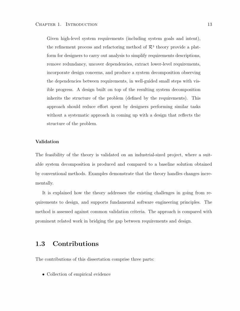
Given high-level system requirements (including system goals and intent),
the refinement process and refactoring method of R3 theory provide a plat-
form for designers to carry out analysis to simplify requirements descriptions,
remove redundancy, uncover dependencies, extract lower-level requirements,
incorporate design concerns, and produce a system decomposition observing
the dependencies between requirements, in well-guided small steps with vis-
ible progress. A design built on top of the resulting system decomposition
inherits the structure of the problem (defined by the requirements). This
approach should reduce effort spent by designers performing similar tasks
without a systematic approach in coming up with a design that reflects the
structure of the problem.
Validation
The feasibility of the theory is validated on an industrial-sized project, where a suit-
able system decomposition is produced and compared to a baseline solution obtained
by conventional methods. Examples demonstrate that the theory handles changes incre-
mentally.
It is explained how the theory addresses the existing challenges in going from re-
quirements to design, and supports fundamental software engineering principles. The
method is assessed against common validation criteria. The approach is compared with
prominent related work in bridging the gap between requirements and design.
1.3 Contributions
The contributions of this dissertation comprise three parts:
• Collection of empirical evidence
Chapter 1. Introduction 14
The empirical evidence includes two empirical studies and an in-depth literature
survey. One empirical study is on an industry approach of solving the design
problem of a complex information system. The other empirical study is a series
of interviews with experienced software architects on the topic of the Meaning of
Software Architecture. The survey describes the existing approaches to addressing
the problem of bridging the gap between problem space (requirements engineer-
ing) and solution space (architectural design) in the software development domain.
Specific requirements refinement and decomposition approaches as well as the use
of refactoring in software engineering are carefully reviewed and analyzed.
• A theory defining refinement, refactoring, and decomposition in requirements con-
text and providing a refinement model
The theory explicitly defines refinement, decomposition, refactoring, and their rela-
tionships in the requirements analysis context, establishes the meaning of require-
ments refactoring, and defines requirements abstraction levels and phases, as part
of the refinement process model where user concerns and designer expectations in
requirements are separately analyzed when appropriate.
• A method for applying refactoring to requirements to obtain a decomposition, fol-
lowing a refinement process
The method introduces specific requirements refactoring operators and algorithms
for refining requirements at four different abstraction levels in obtaining require-
ments decompositions. Relevant perspectives are used to allow design concerns be
incorporated into requirements more systematically and easily. Dimensions are used
to capture and define the design concerns. Five dimension heuristics are defined,
capturing common design concerns.
Chapter 1. Introduction 15
1.4 Dissertation Outline
The dissertation is organized as the following:
Chapter 2 surveys methods of decomposition, refinement, and refactoring in the con-
text of requirements engineering and software engineering, and gives a critical anal-
ysis of the role of decomposition, refinement, and refactoring in requirements engi-
neering.
Chapter 3 presents evidence collected from two empirical studies in the key issues of
the transition from requirements to architecture, which provides the motivation to
the work on requirements refactoring in addressing the issues.
Chapter 4 presents a simple requirements refactoring method applied to a small ex-
ample in illustrating the effect of requirements refactoring. The example gives the
insight to the meaning and role of requirements refactoring, which leads to the main
work of the thesis, a refactoring-based refinement theory.
Chapter 5 presents a refactoring-based requirements refinement theory, a requirements
refinement process model (or framework), and a requirements refactoring method
consisting a set of operators (transformations) and algorithms defined to apply in
the refinement process. The properties of the operators are discussed.
Chapter 6 presents the application of the theory to an industry case study and how
changes in requirements are handled by the framework. A comparison to an existing
solution is included.
Chapter 7 presents the validation of the theory including critical analysis of the method,
existing challenges addressed, principles supported, discussion of limitations, and
comparison to related work.

Chapter 1. Introduction 16
Chapter 8 concludes the dissertation, presents the contributions, and sets out further
research topics.

Chapter 2
Requirements Decomposition,
Refinement, and Refactoring
This chapter analyzes three software engineering techniques, decomposition, refinement,
and refactoring. The first two are often used in the approaches that attempt to address
the boundary problem between requirements engineering and architectural design as
shown in Section 1.1.1. The last one is commonly applied to programming and design;
we examine its use to gain insight to its applicability in the requirements domain.
Section 2.1 reviews the foundation of requirements engineering. Sections 2.2 and 2.3
review methods of decomposition and refinement in the context of requirements engi-
neering. Section 2.4 examines the role of refactoring in software engineering and surveys
relevant work. Section 2.5 concludes with a critical analysis of the surveyed work.
The relevant work in decomposition and refinement are selected based on the following
definitions which are established based on how the terms are commonly used in the
literature and my initial understanding.
Decomposition is about breaking a complex description into parts such that each part
is simpler than the whole.
17

Chapter 2. Requirements Decomposition, Refinement & Refactoring 18
Refinement is a process of adding details to requirements towards defining specifica-
tions. For example, goal-oriented refinement.
2.1 Foundation of Requirements Engineering
In the well-cited paper [ZJ97], Zave and Jackson articulate four areas in the formal
aspects1 of requirements engineering where the foundation work is weak. As problems
are exposed, solutions are proposed, and a ground-work for requirements engineering is
laid out. We use their theory as the context for this survey and adopt their definitions
of domain knowledge, requirements and specifications.
Domain knowledge, or assumptions, refer to the indicative statements that describe
the environment in the absence of the machine. Requirements are optative statements
that describe the environment as we hope it will become. Specifications are imple-
mentable2 requirements. Jackson defines that a specification is “an optative description,
produced during development, of the desired behavior of the machine in a subproblem”
in [Jac01]. The four areas of problems and proposed solution are summarized below.
Terminology – In requirements engineering, all terminology should be grounded in the
environment where the machine3 will reside. The key idea is that clear and precise
definition must be provided to all the terms used. In particular, “designations” are
given to the primitive terms.
In addition, three related issues are discussed. First, the difference between asser-
tion and definition is revisited due to the introduction of designations. Assertion
1As opposed to the sociological aspects such as communicating with customers, conflict resolutionand requirements negotiation.
2It refers to “implementability in principle” [ZJ97] which means a desired behavior from a machine.3Jackson uses the term “machine” to refer to the “computer-based artifact that is the target of
software development”, and the term “system” to refer to “a general artifact that might have bothmanual and automatic components, such as an ‘airline reservation system’ ”.

Chapter 2. Requirements Decomposition, Refinement & Refactoring 19
may introduce new designations. A definition however is made in terms of other
designation(s) and precludes a designation of the defined term.
Next, although requirements engineering is about satisfying goals, to begin with
goals is insufficient. The reason is goals cannot be independently specified and
reasoned without a well defined subject matter and the designations of observ-
able phenomena circumscribe the space of the context and give meaning to goal
reasoning.
Last, issues of identity can be moderated by using clearly defined designations.
Environment – Descriptions made in requirements engineering should not be about the
construction of the machine, but about the environment both with and without the
machine.
Requirements should describe what is observable at the interface between the en-
vironment and the machine. To describe anything else about the machine is con-
sidered as “implementation bias”. State is frequently used in formal specifications.
This imposes a serious problem as specifying internal (non-observable) machine
states in requirements introduces implementation bias. To eliminate this problem,
Zave and Jackson proposed to describe the environment through both indicative
and optative moods. Indicative statements are assumptions or domain knowledge
of the environment. They describe the environment in the absence of the machine
or regardless of the actions of the machine. Optative statements describe what we
would like the environment to be in the presence of the machine. They are com-
monly known as requirements. Designations cannot be used toward components
of the machine state because they may not directly correspond to the real world.
These concepts are further elaborated later during the discussion of the meaning
of requirements.

Chapter 2. Requirements Decomposition, Refinement & Refactoring 20
Formal Description – While describing actions and states using formal descriptions,
it is important to identify and indicate what is controlled by the environment, by
the machine, or shared between the two. Furthermore, it should be possible to
make assertions and constraints about all three types of actions.
Domain Knowledge – The role of domain knowledge in requirements engineering is
to help refine requirements into implementable specifications. Only correct specifi-
cations combined with domain knowledge may deduce requirements satisfaction.
To strengthen the foundation work further, in the same year, Jackson provided a
comprehensive definition to the meaning of requirements in [Jac97]. He indicated that
“requirements4 are located in the environment” and “they are conditions over the events
and states of the environment”. In addition, the requirements do not directly concern
the machine, but concern the environment into which the machine will be installed. The
environment and the machine both possess private and shared phenomena. A distinction
must be made within the shared phenomena between those that are controlled by the
machine and by the environment.
The structure that describes the requirements must make the distinction between two
types of environment properties. One is the indicative properties, those that are given
by the environment. These properties are guaranteed by the environment, and should
already take into account the effects of the machine5 (bad prediction will eventually lead
to failure). We call it the environment assertion, E . The other is the optative properties,
those that must be achieved by the machine. These properties are guaranteed by the
machine. We call it the requirement, R. The full description of the requirements must
include both E and R.
4Functional requirements.5This ensures that both types describe the environment properties that hold during the same time
frame.

Chapter 2. Requirements Decomposition, Refinement & Refactoring 21
A specification, S, describes a condition over the shared phenomena between the
machine and the environment. It is optative and can be formalized. A machine satisfying
S ensures the satisfaction of R:
E ,S ` R
A specification is a bridge between the environment and the machine. It connects a re-
quirement with a program, allows requirements engineers to reason about the satisfaction
of requirements without looking into the program (machine), and allows programmers to
analyze the fitness of the program for its purpose without stepping out into the environ-
ment. It must also be satisfiable without the environment properties so that a machine
can be built accordingly.
In order to describe the usually informal requirements of the environment, designa-
tion is introduced. It allows us to associate a formal ground term6 with environment
phenomena. The goal is to define an unambiguous rule for recognizing a phenomenon.
Although it may be informal, it must be precise enough to describe the world (with the
machine) as it is and as it will be during the operational life time of the machine.
2.2 Requirements Decomposition
Decomposition is not a new topic and has been used and discussed in many fields under
many topics [Sim96, BC99, Lev00]. The section is not intended to be a review of the
philosophy behind the concept, but rather a particular perspective on its use and purpose
in requirements engineering and how it relates to other techniques like refinement and
refactoring.
Large software systems have a high degree of complexity and that is also true of
6“Ground terms for a description are the terms that fix the relationship between the description andwhat it describes.” [Jac97]

Chapter 2. Requirements Decomposition, Refinement & Refactoring 22
their requirements. To reduce the complexity, methods of decomposition are employed.
Specifically, in the domain of requirements engineering, decomposition is about breaking
the complex problem with a set of entangled requirements into smaller, manageable
parts. Sometimes, grouping and composition are used within a decomposition process.
The purpose of requirements decomposition is to assist further elaboration and refinement
of requirements, and possibly to elicit new requirements.
There is no unified view on requirements decomposition. Different methods impose
different views. The following approaches are identified in the literature and are reviewed
in depth.
• Requirements Partition
• Problem Decomposition
• Goal Decomposition
• Formal Methods
• Viewpoints
• Traceability
2.2.1 Requirements Partition
Earlier work on system decomposition tends to use a bottom-up approach in which it is
assumed that a system has a set of requirements, each being a sentence or a paragraph
that specifies the behavior of the system. Two notable approaches are used in partitioning
requirements – functional and utility partition methods. The former is geared to the
developer, while the latter at the user.
Chapter 2. Requirements Decomposition, Refinement & Refactoring 23
Functional Partition
Parnas originally introduced modularization for improving flexibility and comprehensi-
bility in design [Par72]. We review this work here for three reasons: (i) Parnas’ notion of
modularization is the same as our decomposition; (ii) the ideas he used to achieve func-
tional partition are equally applicable to requirements; (iii) requirements engineering was
not separate from software design at that time.
In his paper, Parnas argued that to make the modularization (decomposition) effec-
tive, clear criteria must be defined. Two modularization schemes are provided to the
KWIC (Key Word In Context) example: conventional vs. unconventional. Both will
work and may conceivably produce two identical systems after assembly, but the former
supports only runnable representation, and the latter supports all representations used
for running, changing, documenting, understanding, etc. The two systems are not iden-
tical on the representations other than for running. Even though the paper is on the
topic of design decomposition, it can be viewed as an example of refactoring with both
requirements and design elements. The main difference between the two decompositions
is the criterion used in deducing them. The former used the criterion of making the
major steps as modules (or parts, or components), which can be accomplished using a
flow chart. The latter used the criterion of information hiding [Par71] which is achieved
by the following decomposition rules: begin with a list of difficult design decisions or
design decisions which are likely to change, create individual modules to hide each design
decision from the others.
Decomposition per se does not need to be concerned with other non-functional goals7.
However, to evaluate a decomposition, one needs to care about other non-functional
goals. Refactoring is implicitly used in achieving these goals as in the second example
7Goals other than to reduce complexity by breaking a whole into parts.

Chapter 2. Requirements Decomposition, Refinement & Refactoring 24
given by Parnas in [Par72]. Decomposition here can be viewed as a means to achieve the
refactoring ends.
Utility Partition
Hsia and Yaung introduced a scenario and graph theory based requirements clustering
algorithm for decomposing software systems [HY88]. In this algorithm, requirements are
represented as the vertices and relations between requirements are the edges. A set of
scenarios are defined to set up the initial requirement clustering. Inter-requirements rela-
tions such as restrictive, functional, object-based and independent are used to define a set
of ordinal cohesion coefficients. These coefficients are then used to refine the clustering.
As a result, a set of semi-independent operational entities, clusters, are identified.
Improvements were made to this algorithm by removing the scenarios-based initial
clustering setup in [Yau92] without changing the principles behind the algorithm. This
allows more automation and reduces the amount of user input. It also provides explo-
ration alternatives to the clustering structures by manipulating the threshold of inter-
requirements relations.
This approach uses a depth-first development strategy [Hua87] and is suitable for
feature-based requirements. Since the user must determine the relation between any pair
of requirements in order to assign a cohesion coefficient, and the assignment of these
relations requires implementation level of analysis and reasoning, this approach is not
suitable for implementation-independent high-level requirements specifications.
2.2.2 Problem Decomposition
Jackson explored decomposition towards reuse quite early on and advocated that a paral-
lel structure is more broadly needed than a hierarchical structure [JJ96]. Building upon

Chapter 2. Requirements Decomposition, Refinement & Refactoring 25
his foundation work [Jac97, ZJ97], Jackson described various patterns capturing both
the indicative and optative properties in different domains. These patterns together with
known solutions are referred to as problem frames [Jac01].
“A problem frame characterizes a class of elementary simplified problems that
commonly occur as subproblems of larger, realistic, problems. The intention
is to analyze realistic problems by decomposing them into constituent sub-
problems that correspond to known problem frames.” [Jac00]
Examples of problem frames are: (i) Simple Behavior, e.g. an automatic braking system
for a car; (ii) Simple Information Answers, e.g. answering questions about the weather;
(iii) Simple Information Display, e.g. controlling the display in a hotel lobby that shows
the current positions of the lifts; and (iv) Simple Workpieces, e.g. the control of setting
a VCR memo to record a TV program.
Jackson specifically focused on problem decompositions in [Jac00] using problem
frames and discussed how to decompose a given problem into subproblems of recog-
nized classes captured by problem frames. Here is a summary of decomposition methods
presented.
• Outside-In Decomposition — try to find recognizable parts or aspects of the prob-
lem that correspond to known frames, and analyze them in the context of those
frames. This approach can be viewed as an iterative application of a well-known
heuristic – divide and conquer – start with a piece of the problem that you can solve
and eventually turn the original problem into a recognizable small subproblem.
The risk is that an optimal (or good) solution may not be found since the recognized
parts are chosen randomly, thus the problem is solved randomly too.
• Inside-Out Decomposition — apply a frame only approximately and push unac-
counted difficulties into subproblems that may need other frames. The implicit
Chapter 2. Requirements Decomposition, Refinement & Refactoring 26
assumption is that the subproblems can eventually be solved. A known heuristic
that characterizes this one is: ignore complications and solve the simpler problem.
• Decomposition by Subproblem Tempo — decompose along the dimension of a con-
sistent temporal granularity. When a problem exhibits two or more clearly different
tempi, that is a strong indication of a contour along which distinct subproblems can
be recognized. An example is the two tempi exhibited in a library system: member-
ship subscription and renewal, and checking out and returning books. Each tempo
indicates a subproblem.
Other decomposition heuristics mentioned in [Jac01] are given to guide the recognition
of problem frames.
• Identify the core problem
• Identify ancillary problems
• Standard decompositions of subproblems
• Identifying concerns and difficulties
• More than two moods
• Complex domain or requirement
• Modeling the user
Follow-up work added design refinement extension by associating problem frames with
architectural styles [HJL+02, RHJN04].

Chapter 2. Requirements Decomposition, Refinement & Refactoring 27
2.2.3 Goal Decomposition
In a goal-oriented approach, goal decomposition is used to decompose high-level goals
in order to derive requirements. However, goal decomposition is rarely used in isolation
from goal refinement in any proposed methods. To avoid redundancy, we only review the
notations used towards goal decompositions and leave more refinement specific techniques
to section 2.3.1.
One well-known way to decompose goals is through AND- and OR-decomposition
links [DvLF93]. An AND-decomposition link relates a goal to a set of lower-level goals
(subgoals) such that the satisfaction of this goal depends on the satisfaction of all sub-
goals. An OR-decomposition link relates a goal to a set of subgoals in a disjunctive way,
i.e. the satisfaction of this goal depends only on the satisfaction of one alternative sub-
goal. Other widely used notations include conflict and contribution links. Conflict links
can be used between two goals when the satisfaction of one precludes that of the other.
Contribution links (can be either positive and negative) are introduced by Chung et al.
as a means to achieve (or satisfice) softgoals [CNYM00].
Specific decomposition methods are presented by Mylopoulos et al. in [MCN92,
CNYM00] for non-functional requirements – accuracy and performance. The performance
decomposition methods can be seen as a more specialized subset of accuracy methods.
Therefore, we only review the accuracy goal decomposition methods below.
• Subclass method — Treat the argument of the goal as a class and decompose into
subgoals that use the specialized subclasses as arguments.
• Individual Attribute method — Treat the argument of the goal as a class and
decompose into subgoals that use the attributes of the class as arguments.
• Subset method — When a set of information items are involved in establishing a

Chapter 2. Requirements Decomposition, Refinement & Refactoring 28
non-functional requirement goal, establish the same requirement for each item in
subgoals.
• Derived Info method — When a set of information items are involved in establishing
a non-functional requirement goal, establish the same requirement for the function
that derives them and the source parameters in subgoals.
• Attribute Selection method — To establish a non-functional requirement goal that
is obtained by a sequence of attribute selections (e.g., Joe.project.budget), estab-
lish the requirement for each sub-sequence of attributes in subgoals (e.g., Joe.project,
Project.budget).
• Conservation method — To establish a non-functional requirement goal through (i)
its reception from external agent, and (ii) its internal manipulation by the system.
• Correct External Manipulation method — To establish that the path of the re-
ceipt of information involved in a non-functional requirement goal supports the
requirement.
Decompositions are also used for early requirements where the focus is to model and
elicit the business requirements [Yu95, Yu97, YM00]. The i∗ Framework, introduced by
Yu [Yu95], has two kinds of models. The first is the strategic dependency model which
describes the inter-dependencies of actors. In this model, decomposition of dependency
relations is done between actors where the objects needed in this relation are identified
pertaining some goals. The object can be a goal, task, resource or softgoal. The level
of the dependency can be open, committed or critical. The second is the strategic ra-
tionale model which describes the internal relations of various intentions for each actor,
and how the relations affect the actor’s dependencies on others. Decompositions of the
internal elements including goal, task, resource and softgoal are performed. Extensions

Chapter 2. Requirements Decomposition, Refinement & Refactoring 29
to this framework are made towards agent-oriented development methodology from early
requirements to design to implementation in [BPG+01, BPG+04].
2.2.4 Formal Methods
Moore proposes a formal method in decomposing software system requirements to com-
ponent requirements [Moo90] using the Trace Model of Hoare’s communicating sequential
processes (CSP) [Hoa85]. In Moore’s paper, a “system” is viewed as a network of com-
municating components (or processes); a system is considered “trustworthy” if there is
an acceptably high probability that it satisfies all its critical requirements; a “require-
ment” is a statement of a property; and a “specification” is a statement that a system,
or process satisfies some property.
Three rules are used to form the basis of the decomposition method Moore proposed.
The compose operator is represented as | \ |.
Rule 2.1 The alphabet and traces of a compose process contain only the external com-
munication events in which the process may engage. Thus, each valid trace of a compose
process corresponds to some valid trace of the related concurrent process as follows:
∃tr′.(V alidTrace(tr′, P‖Q) ∧ tr = (tr′ � (αP ÷ αQ)))
⇐ V alidTrace(tr, P | \ |Q)
Rule 2.2 Reduce the problem of proving requirements of a compose process to proving
requirements of a concurrent process:
(P | \ |Q) sat R ⇐ (P‖Q) sat R
∧ ∀tr.(V alidTrace(tr, P | \ |Q)
⇒ ∃tr′.( V alidTrace(tr′, P‖Q)
∧ (tr = tr′ � (αP ÷ αQ))
∧ (R(tr′)⇒ R(tr))) )

Chapter 2. Requirements Decomposition, Refinement & Refactoring 30
Rule 2.3 Reduce the problem of proving requirements of a concurrent process to proving
requirements of its components:
(P‖Q) sat T ⇐ ((P sat S) ∧ (Q sat R)
∧ ∀tr.(V alidTrace(tr, P‖Q)
⇒ ((S(tr � αP )⇒ S(tr))
∧ (R(tr � αQ)⇒ R(tr))
∧ ((S(tr) ∧R(tr))⇒ T (tr)))))
Further readings of the above formalism can be found in [Moo90].
Based on these rules, a seven step decomposition method is described and justified
below.
1. Describe the architecture of the system as a composition of processes that can
be arranged in a binary tree Pi,j, for 0 6 i < n and 0 6 j < 2n−1. Define
the alphabet of the system as the set of external communication channels, and only
those communication channels over which the system is permitted to communicate.
This allows one to describe the system in a hierarchical fashion using tree repre-
sentation such that each subtree is a subsystem.
2. Specify the necessary requirements of the system in the form P0,0 sat R0,0.
The system specification is stated as a requirement R0,0 of P0,0. Subsequent de-
composition will result in a requirement Ri,j, for each process Pi,j, of the system.
For 0 6 i < n and 0 6 j < 2n−1, let SRi,j be the derived synchronization require-
ment for Pi,j defined as true initially. Traverse the tree in a breadth-first manner.
At each non-leaf vertex Pi,j perform the following steps:
3. Define the alphabets of Pi+1,2j, and Pi+1,2j+1. Reduce the specification of the com-
pose process Pi,j to the specification of the concurrent process Pi+1,2j‖Pi+1,2j+1.

Chapter 2. Requirements Decomposition, Refinement & Refactoring 31
4. Derive requirements Ri+1,2j for Pi+1,2j and Ri+1,2j+1 for Pi+1,2j+1 with the goal of
proving Pi+1,2j‖Pi+1,2j+1 satisfies Ri,j.
5. Prove the Concurrent Restriction Condition,
(Ri+1,2j(tr � αPi+1,2j)⇒ Ri+1,2j(tr))
∧ Ri+1,2j+1(tr � αPi+1,2j+1)⇒ Ri+1,2j+1(tr)
6. Attempt to prove the Conjunction Condition,
Ri+1,2j(tr) ∧Ri+1,2j+1(tr)⇒ Ri,j(tr)
If successful, continue the tree traversal to the next vertex at step 3. Otherwise,
specify the weakest condition C needed to complete the proof.
7. Describe C as a conjunction of simple conditions in conjunctive normal form. If no
conjunct depends solely on the traces of either Pi+1,2j or Pi+1,2j+1 then conjoin C
to SRi,j, and continue the tree traversal to the next vertex at step 3. Otherwise,
conjoin to Ri+1,k each conjunct of C that depends only on the traces of Pi+1,k (for
k = 2j or k = 2j + 1) and continue at step 5.
The above method reduces the problem of formally verifying the requirements of
a concurrent system into two separate, simpler problems: (i) verifying that the system
components meet their derived requirements; and (ii) verifying that specific combinations
of those components meet any derived synchronization requirements.
The method proceeds iteratively, until the appropriate requirements for the compo-
nent processes and the minimal set of synchronization requirements are found. An exten-
sion to the CSP notation, involving process composition with hidden internal structure,
promotes hierarchical system design and decomposition. A goal of the decomposition
process is to minimize the number and complexity of the synchronization requirements

Chapter 2. Requirements Decomposition, Refinement & Refactoring 32
since these are the most difficult to verify in later system development. The decomposi-
tion method applies to systems with critical requirements implemented in either hardware
or combinations of software and hardware. The formalism approach enhances the role of
testing and simulation in the design of trustworthy systems.
SCR [HLK95] is another formalism that is commonly used in structuring require-
ments. The basic construct is the Four Variable Model (FVM): monitored, controlled,
input, and output variables. Additional constructs – modes, terms, conditions, and events
– are defined to assist the specification task using FVM. Tables are used as the basic no-
tation to describe the specifications using these constructs. Three types are identified:
condition tables, event tables, and mode transition tables. Formalism for the notation is
established such that automated consistency checking is enabled. Like other formal ap-
proaches, convenient notations are provided but no specific method is given for carrying
out decomposition tasks.
2.2.5 Viewpoints
Viewpoints are used as an effective way to represent different stakeholders’ views during
requirements elicitation [Eas91] and analysis [Nus94]. A viewpoint is defined as “a loosely
coupled, locally managed object, encapsulating representation knowledge, development
knowledge and specification knowledge of a particular problem domain” [NF92]. Nu-
seibeh established the ViewPoints Framework [Nus94] to address the multi-perspective
concerns in software development and used it towards integrating and separating concerns
within requirements. ViewPoint is the primary construct in this framework and is treated
as an object containing Representation Knowledge, Process Knowledge, and Specification
Knowledge. The representation knowledge encodes the representation schemes (meta-
model) for describing the viewpoint. The process knowledge encodes how to use the

Chapter 2. Requirements Decomposition, Refinement & Refactoring 33
representation scheme. The specification knowledge includes three parts: domain, speci-
fication and work record. The first classifies the viewpoint through an identified domain;
the second describes the domain using notations from the representation scheme; and
the third records a history of activities provided in the given process. In this framework,
a system specification is treated as a configuration (structured collection) of ViewPoint
objects (including relationship links).
Although this is one way of decomposing requirements, the emphasis of this frame-
work is not placed on the decomposition because it is done according to the chosen per-
spectives. Rather, the emphasis is on the composition or unification of the perspectives
expressed through viewpoints. This dictates the framework’s focus on method integration
(including the ability to express and enact the relationships between multiple viewpoints
and to describe how to act in the presence of inconsistency) and computer-based tool
support.
Russo et al. conducted a case study on the use of viewpoints in restructuring natural
language-based requirements [RNK99, RNK98]. In the study, a large set of requirements
specifications from a NASA project were decomposed into parts, represented through
viewpoints using different representation styles, and enriched with explicitly defined in-
viewpoint and inter-viewpoint rules that express specific relationships between different
templates, and domain-specific properties within and between the different specification
fragments. In their survey of refactoring techniques [MT04], Mens and Tourwe referred
to the technique used in this case study as requirements refactoring. We disagree with
this view and consider the approach as a decomposition technique because the use of
viewpoints in the study merely placed a structure to the specifications rather than fac-
toring out common parts according to well-defined criteria. Easterbrook et al. conducted
a separate case study [EYA+05] examining the effectiveness of viewpoints in structuring
requirements which further supports our point of view.

Chapter 2. Requirements Decomposition, Refinement & Refactoring 34
Unlike other decomposition methods, where a global view or description is obtained
first and then dissembled into parts, the viewpoints method first collects individual stake-
holders’ views and represents them in possibly different notations, then deals with global
concerns such as consistency and merged view. Viewpoints are used widely, partly be-
cause of the ease of expression when multiple perspectives (or stakeholder) need to be
addressed [NF92]. Because maintaining the consistency among multiple viewpoints is
difficult, most viewpoints-related research chose to focus on automated reasoning and
consistency checking. Some proposed formalism to fix the inconsistency of the over-
lap between viewpoints [SFT99] as opposed to tolerating the existence of inconsistency
[Nus94].
2.2.6 Traceability
The main concern of requirements traceability work is the alignment between stakeholder
requirements and outputs of the software development process [RJ01]. Much of the
research in this area is on reference models and how to maintain traces. A well recognized
definition for requirements traceability is given by Gotel and Finkelstein [GF94] as
“the ability to describe and follow the life of a requirement, in both a forward
and backward direction, i.e., from its origins, through its development and
specification, to its subsequent deployment and use, and through periods of
ongoing refinement and iteration in any of these phases.”
In general, traceability does not contribute to decomposition directly, however, it is an
important aspect that must be carefully considered during decomposition. Having this
in mind, Kirkman analyzed a number of process-oriented requirements decomposition
and traceability problems drawn from the defence industry [Kir98]. His focus is on meta-

Chapter 2. Requirements Decomposition, Refinement & Refactoring 35
issues and the proposed solutions are generally rule-of-thumb rather than well-defined
methods. We discuss the identified problems below.
Excessive or Insufficient System Decomposition Decomposition needs to be per-
formed at the appropriate level of detail according to needs. When a great deal of un-
necessary details are specified about the subsystems at the system-level decomposition,
two main problems can occur. One is that design-related requirements were introduced,
which over-constrained the design of the system architecture. The other is that excessive
decomposition can introduce a significant number of extra requirements, which makes
the internal and acceptance testing of the requirement specifications more complex and
costly. It not only reduces a company’s competitiveness, but also poses the danger of
losing customers. The recommended means of alleviation is not to produce requirements
for a system and a subsystem at the same time. By the same token, insufficient decom-
position can result in system-level requirements not being satisfied by the subsystems
when more than one is involved. Decomposition must be carefully carried out to ensure
all requirements can be satisfied in their entirety.
Unsourced Requirements It is easy to specify what is believed to be a customer’s
needs but may not actually be. In these cases, over-engineered idealistic solutions are
provided in place of pragmatic solutions that fit the customer’s budget. One cause of
the problem is that no traceability to customer’s needs is maintained in the specified
requirements. The way to deal with such problems is to ensure all top-level requirements
come from an approved source and unsourced requirements are either rejected or marked
as optional.
Excessive or Insufficient Requirements Hierarchy Requirements hierarchy is mainly
used for traceability. Too many intermediate hierarchy levels give rise to a larger num-

Chapter 2. Requirements Decomposition, Refinement & Refactoring 36
ber of requirements which makes the requirements management task more complex than
necessary. On the other hand, a minimal hierarchy with baseline requirements has to be
defined to prevent unwarranted cross-hierarchy modification.
2.3 Requirements Refinement
Zave and Jackson define requirements refinement as the process of bridging the gap
between requirements and specifications [ZJ97]. They point out that some requirements
are already implementable and can be used as specifications8. Yet, many requirements are
not readily implementable. This is where refinement is needed – to turn requirements into
specifications. They argued that, in general, there are three reasons why a requirement
fails to be directly implementable and how to deal with each case.
• Its satisfaction depends on constraining an action controlled by the environment.
Such a requirement cannot be satisfied by the machine alone, but by coordinating
specifications with domain knowledge.
• Unshared information is used in describing the requirement. In such a case, it is
needed to refine the requirement using domain knowledge to turn unshared infor-
mation into shared information.
• It references the future in its statement. The way to deal with it is to relate the
future back to the past.
This definition is well adopted by the goal oriented approaches which are reviewed
in section 2.3.1. Other approaches, reviewed in sections 2.3.3 through 2.3.4, do not
differentiate requirements from specifications explicitly, thus do not satisfy this definition.
8Recall from Section 2.1 that specifications are implementable requirements.

Chapter 2. Requirements Decomposition, Refinement & Refactoring 37
Nonetheless, they provide means of elaboration and other useful utilities. At the end of
this section, we discuss our view of requirements refinement and give a new definition.
2.3.1 Goal Refinement
In his keynote speech, van Lamsweerde defined requirements engineering (RE) as a disci-
pline concerned with goals including identification, operationalization and responsibility
assignment [vL00]. In goal-oriented RE, goals are used as the primary entities in specify-
ing requirements and goal refinement becomes a means of requirements refinement. Two
frameworks for goal refinement are reviewed below: a formal one and a qualitative one.
A Formal Framework In the formal framework, KAOS [DvLF93], goal refinements
are captured through AND- and OR- refinement links. Goal decomposition is performed
first to identify subgoals within a refinement step. These refinement links are also referred
to as decomposition links (see section 2.2.3). An AND-refinement link relates a goal to
a set of refined goals (subgoals) so that the satisfaction of this goal depends on the
satisfaction of all subgoals. An OR-refinement link relates a goal to a set of subgoals in a
disjunctive way, i.e. the satisfaction of this goal depends only on the satisfaction of one
alternative subgoal. Conflict links can be used between two goals when the satisfaction
of one precludes that of the other. An operationalized goal assumes implementability
and can be readily (or has been) assigned to an agent9.
In this approach, goals are obtained from the initial document by searching for inten-
tional keywords such as “concern”, “intent”, “in order to”, “objective”, “purpose”, etc.
Goals are typed as Maintain, Avoid, Achieve, Min, Max such that they can be formally
represented using real-time temporal logic [Koy92]. The temporal logic operators are: ◦
9Agents are the active components from either the environment or the system-to-be.
Chapter 2. Requirements Decomposition, Refinement & Refactoring 38
(in the next state), • (in the previous state), ♦ (eventually), � (some time in the past),
� (always in the future), � (always in the past), U (always in the future until), and W
(always in the future unless). Relying only on the initially obtained goals is insufficient
to provide completeness. Refinement is carried out through the elicitation of new goals
by asking “why” and “how” questions [vL00] within the subject matter [ZJ97]. The re-
finement steps end when the subgoals can be assigned to agents either in the environment
or the software-to-be. Terminal goals in the former group are assumptions and the latter
become requirements.
Refinement patterns are introduced by Darimont and van Lamsweerde to provide
formal support to achieve completeness, provable correctness, and integrated alterna-
tives in building goal refinement graphs for the formalizable goals [DvL96]. Two formal
definitions are given to assist provability.
Definition 2.1 A set of goal assertions G1, G2 . . . Gn is a complete refinement of a goal
assertion G iff the following conditions holds
1 entailment G1 ∧G2 ∧ . . . ∧Gn ` G
2 minimality ∀i :∧j 6=iGj 0 G
3 consistency G1 ∧G2 ∧ . . . ∧Gn 0 false
Definition 2.2 A refinement pattern is a one-level AND-tree of abstract goal assertions
such that the set of leaf assertions is a complete refinement of the root assertion.
Refinement patterns are provided in two groups: propositional based and first-order
based. In the propositional group, an Achieve goal, P ⇒ ♦Q, can be refined into the
following alternative refinements. (The names are in correspondence to those given in
the original paper [DvL96].)

Chapter 2. Requirements Decomposition, Refinement & Refactoring 39
Name Subgoal Subgoal Subgoal Subgoal
RP3 P ⇒ ♦R R⇒ ♦Q
RP4 P ∧ P1 ⇒ ♦Q1 P ∧ P2 ⇒ ♦Q2 �(P1 ∨ P2) Q1 ∨Q2 ⇒ Q
RP5 P ∧ ¬R⇒ ♦R P ∧R⇒ ♦Q P ⇒ �P
RP6 ¬R⇒ ♦R P ∧R⇒ ♦Q P ⇒ �P
RP7 P ⇒ ♦R R⇒ R U Q
Benefits of refinement patterns include proved correctness (no further proofs are re-
quired), formal completeness checking, constructive refinement and finding of alterna-
tives, and making explicit choices early. Pattern relevance and retrievability issues are
also addressed.
A number of extensions to the framework are provided: (i) specific support on goal
conflicts is presented in [vLDL98]; (ii) obstacle analysis is presented in [vLL00]; (iii)
modeling anti-goals to capture intruder’s intention is described in [vLBLJ03]; and (iv)
bridging to architectural design is discussed in [vL03].
A Qualitative Framework Mylopoulos et al. created a qualitative framework to rea-
son and refine goals [MCN92, CNYM00]. In it, a set of notations are given to describe
goals, and a weaker versions of the AND- and OR- links are used to refine “softgoals”.
Goals are defined in three mutually exclusive classes: softgoals (or non-functional re-
quirements (NFR) goals), satisficing goals and argumentation goals. Softgoals refer to all
non-functional or quality requirements such as accuracy, security, cost, and performance.
Satisficing goals refer to design decisions that might be adopted to satisfice one or more
softgoals10. Argumentation goals state evidence or counter-evidence for other goals or
10Goals are either satisfied or not. In this sense, “satisfy” is boolean. But for softgoals, satisfactioncannot be stated in a boolean fashion, but rather measured by the degree of its satisfaction. We referto the satisfaction of a softgoal by a given degree as satisficing.

Chapter 2. Requirements Decomposition, Refinement & Refactoring 40
goal refinements.
Chung et al. stated that “refinement methods are generic procedures for refining a
softgoal or interdependency into one or more offspring” [CNYM00] and indicated that
three kinds of refinements can be used to relate softgoals to each other: decomposition,
satisficing and operationalization, and argumentation [MCN92, CNYM00]. Goal decom-
position methods are used to decompose a goal into an AND set of subgoals which have
been reviewed in section 2.2.3. Goal satisficing methods refine a goal into a set of satisfic-
ing goals and commit to particular design decisions. Argumentation methods refine a goal
or a link into an argumentation goal and indicate evidence or counter-evidence in terms
of arguments for the satisficing of a goal. Specific refinements are provided for accuracy,
security and performance requirements in [CNYM00]. As seen, methods and techniques
of this framework are used to refine softgoals towards explicit design decisions.
2.3.2 Refinement Through Non-functional Decomposition and
Conflict Resolution
Poort and de With proposed a requirements refinement scheme through non-functional
decompositions guided by conflict resolution [PdW04]. They believe functional require-
ments, non-functional requirements and architecture should be integrated in one method
and tie their approach closely with architectural design. They claimed that their un-
derlying principle – “in designing system architectures, the supplementary requirements
are more important than the primary requirements”11 – is adopted from a commonly
accepted principle “in designing system architectures, the non-functional or quality re-
quirements are at least as important as the functional requirements”. Their approach is
based on the following observations.
11New terms are defined shortly.

Chapter 2. Requirements Decomposition, Refinement & Refactoring 41
“Cohesive force of supplementary requirements : good architectures tend to
cluster functions with similar supplementary requirements in the same sub-
system.
Divide-and-conquer conflict resolution principle: if a subsystem has to fulfill
conflicting requirements, it is useful to separate the parts that cause the
conflict(s).
Entanglement of function, structure and building process of software: these
three elements are highly interrelated.” [PdW04]
A new model was proposed to categorize requirements as follows. Functional require-
ments can be marked as primary and secondary. The secondary functional requirements
and non-functional requirements are grouped as supplementary requirements. Within the
non-functional requirements, distinctions between quality attributes and implementation
requirements are made. A graph that describes this model is shown in figure 2.1.
Three dimensions of software construction (or solution dimensions) are identified as
process, structure and functionality. Architectural strategies are categorized accordingly
as below.
process – Making choices in the software building process to achieve supplementary
requirements.
structure – Making choices in the structure of the software to influence quality at-
tributes or satisfy other supplementary requirements.
functionality – Building functionality that is specifically aimed at achieving a quality
or implementation objective.
Combining both the problem (requirements) and solution (strategies) dimensions,
Poort and de With introduced a model of a 3×3 matrix as a replacement of the traditional
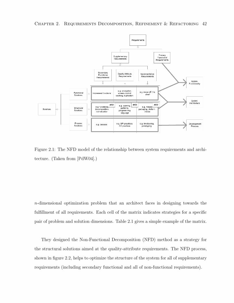
Chapter 2. Requirements Decomposition, Refinement & Refactoring 42
Figure 2.1: The NFD model of the relationship between system requirements and archi-
tecture. (Taken from [PdW04].)
n-dimensional optimization problem that an architect faces in designing towards the
fulfillment of all requirements. Each cell of the matrix indicates strategies for a specific
pair of problem and solution dimensions. Table 2.1 gives a simple example of the matrix.
They designed the Non-Functional Decomposition (NFD) method as a strategy for
the structural solutions aimed at the quality-attribute requirements. The NFD process,
shown in figure 2.2, helps to optimize the structure of the system for all of supplementary
requirements (including secondary functional and all of non-functional requirements).

Chapter 2. Requirements Decomposition, Refinement & Refactoring 43
Functional Quality Attribute Implementation
Requirements Requirements Requirements
Functional
Solutions
Implement required func-
tions
Use encryption, access
control, caching and du-
plication functions
Use COTS products
Structural
Solutions
Use database normaliza-
tion, extraction of generic
functionality, and func-
tional or non-functional
decomposition
Choose program pat-
terns, programming
language, and correct
parametrization
Accommodate incre-
mental deployment
Process
Solutions
Use conventional cascade-
development methods to
prioritize system function-
ality over time and budget
limitations
Use best practices or
conform to standards
Prototype to involve
users
Table 2.1: A simple example of the NFD matrix
The system structure is adjusted with respect to the requirement conflicts12 through
isolating each conflict in a separate subsystem followed by individual subsystem opti-
mizations using process, structural or functional strategies. It is essentially an iterative
divide-and-conquer strategy for resolving requirement conflicts.
In their paper, Poort and de With did not make explicit distinction between require-
ments refinement and decomposition and achieved refinement mostly through the use of
decompositions. However, we categorize their work under refinement because their end
goal is towards design which fits our view.
12Only the conflicts among supplementary requirements
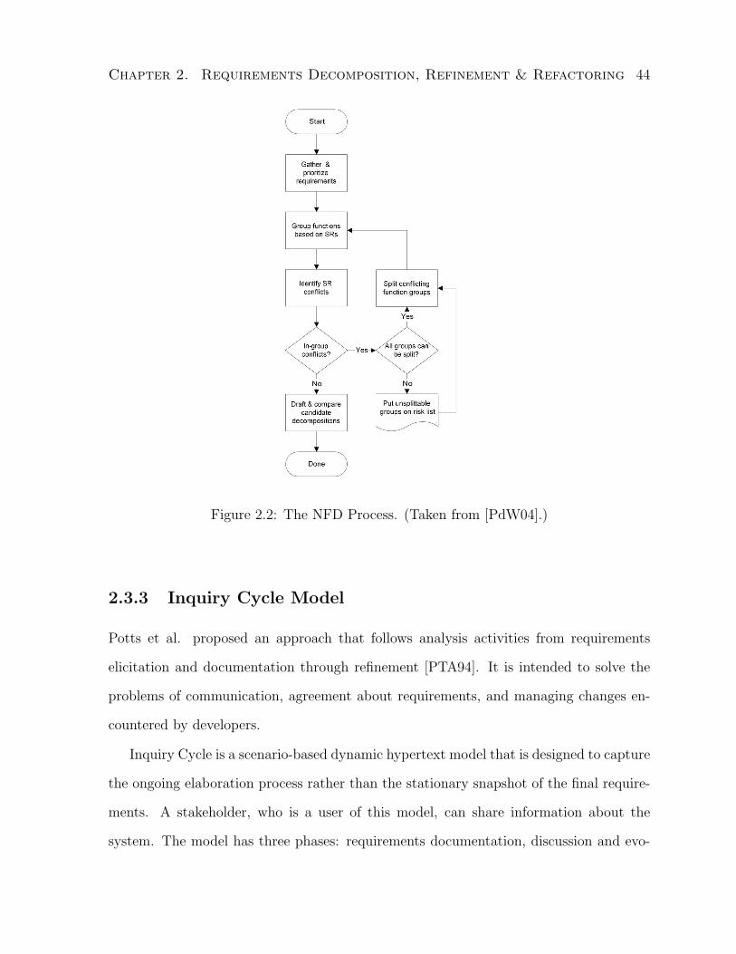
Chapter 2. Requirements Decomposition, Refinement & Refactoring 44
Figure 2.2: The NFD Process. (Taken from [PdW04].)
2.3.3 Inquiry Cycle Model
Potts et al. proposed an approach that follows analysis activities from requirements
elicitation and documentation through refinement [PTA94]. It is intended to solve the
problems of communication, agreement about requirements, and managing changes en-
countered by developers.
Inquiry Cycle is a scenario-based dynamic hypertext model that is designed to capture
the ongoing elaboration process rather than the stationary snapshot of the final require-
ments. A stakeholder, who is a user of this model, can share information about the
system. The model has three phases: requirements documentation, discussion and evo-

Chapter 2. Requirements Decomposition, Refinement & Refactoring 45
lution. At the requirements documentation phase, scenario analysis including use cases
and scripts can be used to elicit requirements. At the requirements discussion phase,
requirements refinements are discovered through “what-if” questions, and their answers
and justifications. At the requirements evolution phase, either commitment or changes
to requirements are made. Putting them together, we get a cyclic model: requirements
documentation, consisting of requirements, scenarios and other information, is discussed
through questions, answers, and justifications; choices may lead to requested changes,
which in turn modify the requirements documentation. A graphical model of the inquiry
cycle is shown in figure 2.3.
Figure 2.3: The Inquiry Cycle Model. (Taken from [PTA94].)
The Inquiry Cycle model has a number of distinct characteristics:
• It is not a rigid process model.
• There is no assumption about language or expressive style.

Chapter 2. Requirements Decomposition, Refinement & Refactoring 46
• Hypertext technology is useful but not mandatory.
This model allows requirements refinement (mostly at the discussion phase) but is
not specifically built for it. Its main goal is to allow analysis of requirements and keep a
hypertext-based history of how analysis and changes are derived.
2.3.4 Process-oriented Refinement
A process framework, proposed by Alcazar and Monzon [AM00], is centered around cyclic
and iterative communications between the user and analyst on the problem (require-
ments) provided by the user and the solution (specifications) suggested by the analyst.
Building a problem domain model is both the primary step in structuring user require-
ments and the central technique used towards user requirements refinement. Figure 2.4
illustrates the basic process activities. The refinement steps are primarily the analysis
and verification steps in the process. Requirements are refined into specifications through
analysis and specifications are verified against requirements.
Capture UserRequirements
Analyze Requirements
VerifySpecification
Build SolutionSpecification
Figure 2.4: Process Activities in the Framework.
The analysis step mainly involves the construction of a problem domain model (con-
ceptual model) from the given requirements. The domain model captures relevant con-

Chapter 2. Requirements Decomposition, Refinement & Refactoring 47
cepts and their relationships within the problem context. The objective is to build a
common understanding of the problem domain concepts and vocabulary among stake-
holders and serve as a reference model and dictionary. The model is constructed either
by static object modeling [BRJ00] or entity-relationship modeling. The specifications are
represented by use cases [BRJ00].
The verification step involves linking each requirement to use case(s) and closing the
iterative process when the links are identified. It is used to confirm that all requirements
have been addressed and provide a path of traceability.
2.4 Refactoring in Software Engineering
Refactoring techniques have been applied widely in software engineering, particularly in
object oriented (OO) design and programming [MT04]. However, there has been little
research done in requirements (re)factoring although hints of its application exist in both
research and practice [Lev03, Sha03b, LCLP05].
In this section, we first review the refactoring concept with a focus on design and
programming; then we provide our account of what constitutes requirements refactoring
and propose a definition for it.
2.4.1 Software Refactoring
Mens and Tourwe provided a comprehensive review of refactoring activities, techniques,
artifacts, tools and processes in software engineering [MT04] with an emphasis on pro-
gram refactoring. Below, we use their survey as a basis to review the concepts of software
restructuring and refactoring in the context of programming, design and requirements.
Software restructuring was introduced to incrementally improve the internal software
quality [Arn89] and is focused on the programs, and in the specific case of object-oriented

Chapter 2. Requirements Decomposition, Refinement & Refactoring 48
programming, it is referred to as refactoring with specially designed techniques [Opd92,
Rob99].
Software Restructuring Arnold described software modification as the most com-
monly occurring software activity [Arn89] and it often leaves the software in a state that
is difficult to understand by those other than its author particularly during maintenance
phase. As a result, the software becomes harder to change, less reliable, and progressively
less changeable. Software restructuring, an area that is particularly targeted on this prob-
lem, is the modifications of software that enhances the understandability, changeability
and susceptibility to future changes. The goal is to improve software maintainability. In
Arnold’s work, “software” refers to both external and internal documentation concerning
source code as well as the source code itself. Restructuring techniques are given in five
types.
• Code – coding style (e.g. pretty printing and code formatting, style standardiza-
tion), packaging reusable code (e.g. restructuring code for reusability), control flow
(e.g. early goto-less approach, boolean flag approach), and data (e.g. third-normal
form).
• Documentation – upgrade documentation, and system modularization.
• Programming Environments/Tools – upgrade the programming environment, pro-
gramming environments/workstations, software metrics, standards checkers and
other aids, tool collections, program transformation systems, and fourth genera-
tion languages.
• Software Engineers – train programmers, and reduce turnover.
Chapter 2. Requirements Decomposition, Refinement & Refactoring 49
• Management and Policies – programming standards and style guidelines, and in-
spections and walkthroughs.
Chikofsky and Cross provided a comprehensive definition for restructuring [CC90]
shown below:
“[It is] the transformation from one representation form to another at the
same relative abstraction level, while preserving the subject system’s external
behavior (functionality and semantics). A restructuring transformation is
often one of appearance, such as altering code to improve its structure in
the traditional sense of structured design. While restructuring creates new
versions that implement or propose change to the subject system, it does not
normally involve modifications because of new requirements. However, it may
lead to better observations of the subject system that suggest changes that
would improve aspects of the system.”
2.4.2 Program Refactoring
In the context of object-oriented development, program structuring is specifically termed
as refactoring by Opdyke first in his thesis [Opd92]. A definition given by Fowler [Fow99]
is shown below:
“[It is] the process of changing a [object-oriented] software system in such a
way that it does not alter the external behavior of the code, yet improves its
internal structure.”
The main idea of program refactoring is to redistribute variables, methods and classes
across the class hierarchy such that future adaptations and extensions can be made easier,

Chapter 2. Requirements Decomposition, Refinement & Refactoring 50
thus improving software quality. The basic refactoring steps are called primitive refac-
toring. Examples of these are MoveMethod, RenameMethod, ExtractMethod, PullUp-
Method, and AddClass. They are elementary behavior-preserving transformations and
serve as basic unit of refactoring. A composite refactoring is made up with a sequence of
primitive refactorings. Illustrative examples can be found in [MT04].
The refactoring process has been established, with the following activities.
1. Identify where to apply which refactoring
2. Guarantee that the refactoring preserves software behavior
3. Assess the effect of refactoring on quality
4. Maintain consistency after refactoring
Numerous techniques have been proposed for refactoring and two formal approaches
are most frequently used: (i) invariants, pre- and post-conditions; and (ii) graph trans-
formation.
It is not enough to be able to refactor without any guarantees on either the cor-
rectness or properties of the resulting program. Unfortunately, determining program
correctness after updates is an undecidable problem. However, program preservation can
be evaluated either statically or dynamically. Static preservation example is checking the
refactoring preconditions and a dynamic one is object equivalence test [MT04].
2.4.3 Design Refactoring
Refactoring at the code level is not always adequate since some problems can only be
spotted at a higher level of abstraction. UML (Unified Modeling Language) [BRJ00],
as a commonly used description language in design, has been given its own refactoring

Chapter 2. Requirements Decomposition, Refinement & Refactoring 51
schemes. In [SPLJ01], Sunye et al. proposed a set of behavior preserving transforma-
tions (or refactorings) that make structural changes for UML models. The goal is to make
modifications to existing products easier and allow the designers to evaluate the impact
of one change over the whole model. These transformations are not limited to refactoring
class diagrams, but to refactoring the design of statecharts as well. For the former, two
categories are introduced: (i) add, remove and move; and (ii) generalization and special-
ization. For the latter, single state based and composite state based transformations are
provided separately. The limitations of their work include:
• reliance on known structural design patterns to make changes
• resulting design has to be predetermined
• changes not always bring improvement
• refactoring is limited to structural mappings between predetermined designs
• refactoring itself does not help to improve design quality but to realize (predeter-
mined) structural design changes
Design patterns [GHJV95] are widely practiced to enhance quality. The introduction
of design pattern instances into the design is accomplished through refactoring. Although
design patterns provide a level of abstraction, they are nonetheless mostly focused at the
implementation level. At the architectural level, architectural styles [SG96] can be used
in place of design patterns for refactoring.
Tokuda and Batory’s work on object-oriented design evolution [TB99] is also focused
on design refactoring. They identified three kinds of evolution: schema transformations,
design pattern microarchitectures, and hot-spots. Schema transformations are drawn
from object-oriented database schema transformations that perform edits on a class di-
agram [BK87]. Examples are adding new instance variables and moving methods up

Chapter 2. Requirements Decomposition, Refinement & Refactoring 52
the class hierarchy. Design patterns are recurring sets of relationships between classes,
objects, methods, etc. that define preferred solutions to common object-oriented design
problems [GHJV95]. Hot-spots are aspects of a program which are likely to change from
application to application [Pre94]. Designs using abstract classes and template meth-
ods are prescribed to keep these hot-spots flexible. This level of design refactoring is
nevertheless low level and tightly linked to code level refactoring.
2.5 Critical Analysis
In this section, I provide an analysis of each surveyed technique and an overall discussion.
2.5.1 On Decomposition Criteria
In general, decomposition is used to reduce the complexity of the original problem, and to
break down to smaller and well-contained subproblems such that each can be represented
and solved more simply. In any requirements decomposition method, merely having just
any decomposition is rarely sufficient; there are other goals to achieve. To Parnas [Par72],
the goal is to satisfy modularization criteria for better design. To Hsia and Yaung [HY88],
the goal is to achieve high cohesion and low coupling through inter-requirements relations.
To Jackson [Jac01], the goal is to reuse through patterns. For goal-oriented approaches
[DvLF93, MCN92, CNYM00], the aim is to satisfy high-level goals and/or non-functional
requirements. To Moore [Moo90], the goal is provability. For viewpoints, the goal is to
capture multiple perspectives and use them towards integrating and separating concerns
within requirements. For traceability, the goal is to keep the traces to ensure requirements
satisfaction.
We can view the additional goals as evaluation criteria for the resulting decomposition.
These criteria will be used to guide refactoring and are therefore also referred to as the
Chapter 2. Requirements Decomposition, Refinement & Refactoring 53
refactoring criteria. We will revisit this topic in Chapter 5.
2.5.2 On Refinement and Design
Jackson’s theory of requirements indicates that requirements lie in the environment and
refinement is a process of going from requirements to specifications (implementable re-
quirements) [Jac97]. In this process, decomposition is often a useful tool. If specifying the
problem is all we needed to accomplish, then we are done after these steps of refinement.
However, in most cases13, that is not the end of software engineering project. What
follows is the construction and delivery of a system that solves the problem. Individual
specifications may be implementable, but to satisfy them collectively, it requires careful
planning. Naturally, we move into design realm. As a bridge, we can use requirements
refinement as a means towards design. This direction and tendency are evident in the
approaches of sections 2.3.1 and 2.3.2.
We define requirements refinement as not only a process of going from requirements
to specification, but also a process to discover design perspectives. The goal is to find
an initial suitable design that can fulfill the requirements and allow the construction of
a useful software system that solves the indicated problem.
2.5.3 On the Role of Refactoring
Mens and Tourwe gave a requirements refactoring example in [MT04]: using viewpoints
in restructuring natural-language-based requirements [RNK98]. It was suggested that
viewpoints help increase the requirements’ understandability, ease the detection of incon-
sistency, and enhance the manageability of requirements evolution. Given the review in
Section 2.2 and above analysis on decomposition criteria, the aforementioned viewpoints
13Except when the problem is not worth pursuing and the project is cancelled after initial investigation.

Chapter 2. Requirements Decomposition, Refinement & Refactoring 54
work (by Russo et al.) would fit under requirements decomposition more appropriately.
Its effort may contribute to requirements refactoring, but does not define requirements
refactoring. If so, what is requirements refactoring? It has not been explicitly defined or
studied in the literature.
In my opinion, there is more to requirements refactoring than the benefits brought
by the use of viewpoints listed above. Specifically, requirements refactoring should be
paving a road towards better design.
As we have seen in sections 2.4.2 and 2.4.3, both program and design refactoring are
intended to make the subsequent software evolution and maintenance easier by making
the artifact more mathematical and enabling its processing to become more mechanical.
This is also part of the goal of requirements refactoring – to ease the subsequent devel-
opment work, particulary the architecture and design, and to make it more mechanical.
One way of achieving this goal is to reduce the complexity of requirements (thus reduc-
ing misinterpretations) and ensure the correctness of representation. This provides the
motivation behind requirements refactoring.
Earlier, we have mentioned that requirements refinement is a means towards design,
and decomposition is one of its tools. The role of requirements refactoring is to reveal
further properties of and relationships between requirements so that a better design can
be found. One way to achieve this is through predefined refactoring dimensions. These
dimensions are defined in terms of refactoring criteria. We use a number of examples
below to illustrate this idea.
One way to identify the dimensions is through the use of design principles. Each
principle represents a refactoring dimension and its content defines the refactoring crite-
ria. Design principles are often geared at achieving non-functional requirements. In the
KWIC (Key Word In Context) example [Par72], we can identify the following refactoring
dimensions.
Chapter 2. Requirements Decomposition, Refinement & Refactoring 55
• flexible data — predefine basic data structure and storage mechanism — using a
flexible data structure makes input parsing easy because the logic is encapsulated
in the parsing unit, and makes sorting efficient because no extra copying or storage
space is needed. It also allows different data types to be used without affecting the
rest of the program.
• weakest acceptable condition — the improvement made in circular shift module is
in fact a way of refactor the design so that unnecessary inner design decisions do
not have to be revealed.
• reusability of a module — when a number of utilities need to be used in many
places as a bundle or they share similar characteristics in the service they provide,
it is a good idea to group them together into one module
Architectural styles [SG96] offer heuristic approaches for refactoring requirements in
specific contexts. The purpose is both reasoning about quality attributes [CKK01] and
reuse as the styles can serve as guides to many similar problems that need requirements
refactoring. This approach usually requires pattern recognition and matching. Once the
style is recognized, requirements are shaped to fit what is required by the style. This
is a typical design heuristic. From this example, we see that refactoring is necessary to
come up with a design. How to perform refactoring and what is the necessary condition
for choosing refactoring techniques? First, a set of criteria must be defined so that the
end goal of refactoring is clear. Refactoring activities can then be carried out along the
dimensions defined in the criteria towards discovering a better design.
Another example of refactoring could be along the simplicity dimension: to determine
whether two requirements are really just one when highly related (or redundant) infor-
mation are present, or whether one requirement should be split into two when disjoint

Chapter 2. Requirements Decomposition, Refinement & Refactoring 56
concepts are present. Jackson’s decomposition by subproblem “tempo” can be used as a
splitting criterion in this dimension [Jac01].
The non-functional requirements-based refinement method reviewed in Section 2.3.2
also has an element of refactoring. The refactoring dimension can be viewed as along
conflicts resolution within the supplementary requirements.
2.5.4 Concluding Remarks
The overall survey shows that decomposition methods are abundant and refinement meth-
ods are adequately available. However, both are often determined by the general ap-
proach a method undertakes, for example, a goal-oriented approach, or a formal method.
Nonetheless, it reflects the fact that these two techniques are valued in requirements
engineering. On the other hand, there is virtually no requirements refactoring method
offered in the research community. It shows either a lack of appreciation of the technique
or an inadequacy in the understanding of the topic.
In order to produce a system design that can withstand change and the test of time,
designers must gain a deep understanding of the problems, i.e. the requirements. These
three analysis techniques are the basic tools in this respect and their contribution is rec-
ognized in the literature, although it has not necessarily been taken full advantage of.
It is conceivable that a good requirements analysis method should incorporate all three
techniques so that designers have access to all three techniques without the burden of
integrating multiple potentially incompatible methods. In this light, the requirements
refactoring technique is both under-appreciated and understood poorly to date, yet pos-
sesses high potential as a useful tool. This observation has motivated the subsequent
work on requirements refactoring presented in this dissertation.
A number of other observations also arise from this survey. Firstly, in many ap-

Chapter 2. Requirements Decomposition, Refinement & Refactoring 57
proaches surveyed, decomposition and refinement are used interchangeably and not well
distinguished. It is mostly due to their intertwined activities in the analysis process.
Nonetheless, they do represent two different concepts. One difference between decompo-
sition and refinement is with respect to hierarchy. A clean decomposition is independent
from having a hierarchical structure [Par72], but refinement constructs a hierarchical
structure with the refinement relation being the basic relationship holding the structure.
Based on the review and analysis included in the survey, requirements decomposition is a
tool for refinement (as well as refactoring) and it is not meaningful to use decomposition
alone without other goals.
Secondly, in most decomposition methods, the criteria for decomposition are not pro-
vided, making the method hard to evaluate. Often, a notation and/or a process are given
as part of the method instead. As Parnas has pointed out back in the 70’s [Par72], the ef-
fectiveness of decomposition depends on such criteria and had been seriously overlooked.
From this survey, we see that it is still the case in the requirements engineering field.
I believe that to evaluate a decomposition, non-functional requirements must be taken
into account. Achieving the non-functional requirements is precisely the goal of refactor-
ing. Decompositions become the means to achieve the refactoring ends. Moreover, the
refactoring criteria provide the necessary conditions for evaluating decompositions.
Thirdly, some methods considered decomposition but overlooked refactoring. The
ViewPoints Framework [Nus94] is an example. It adopts the natural perspectives received
from stakeholders (or other sources) and proposes a decentralized architecture through
viewpoints. However, the architecture is completely dictated by the perspectives used
in creating the viewpoints. Since there is no guarantee on the structure of the initial
perspectives, there is no guarantee that the structure of the distributed architecture
is well-designed. This is the main weakness of that approach, but the situation can be
improved through refactoring on the initial perspectives and selective use of well-designed

Chapter 2. Requirements Decomposition, Refinement & Refactoring 58
viewpoints instead of the naturally given ones.
Based on the results of the survey and above analysis, I revise the definition of the
three techniques to the following.
Decomposition is used to reduce the complexity of the original problem, and break
it down to smaller and well-contained subproblems that can each be represented
and solved more simply. It is a useful and essential tool for both refinement and
refactoring and can be evaluated with respect to decomposition criteria.
Refinement is not only a process of going from requirements to specification, but also a
process to discover design perspectives. The goal is to find an initial suitable design
that can fulfill the requirements and allow the construction of a useful software
system that solves the indicated problem.
Refactoring is an optimization process aimed at revealing further properties of and
relationships between requirements so that a better design can be found without
altering the original meaning of requirements.
2.6 Summary
This chapter reviewed the requirements analysis techniques, decomposition and refine-
ment, that are commonly used in approaches moving from requirements to design. The
role of refactoring in software engineering is examined through surveys of software pro-
gram and design refactoring.
In the surveyed work, the terms “decomposition” and “refinement” are often used
interchangeably and the distinctions and relationships between them have not been es-
tablished in the literature. Furthermore, while “refactoring” has been used widely in

Chapter 2. Requirements Decomposition, Refinement & Refactoring 59
software engineering, no existing work provides an adequate support for requirements
refactoring.
An interesting relationship between the three techniques, decomposition, refinement,
and refactoring, is observed which can be utilized to build effective methods.

Chapter 3
Empirical Evidence
I have conducted two empirical studies to investigate the practical issues involved in
crossing the boundary between requirements engineering (problem space) and software
architecture (solution space). The first is a focused study on one software team dealing
with COTS-based developments [LLE05]. The second is a broad study of the “meaning
of software architecture” on multiple software architects from different companies and
domains [LCLP05, LLC+06, LLCP05, LLCP06]. The studies provide evidence to the
key issues in the transition from requirements to architecture and motivate the work on
requirements refactoring in addressing the issues.
3.1 Business Scenario Framework
To understand and address the issues involved in COTS-based (Commercial Off-The-
Shelf) development, an IBM team has collaborated with me on an internal project that
is dedicated to study integration issues and surface component requirements. During the
collaboration, we have investigated the Business Scenario Framework (BSF) approach
taken by the team, documented the process, described the artifacts, and reported find-
60

Chapter 3. Empirical Evidence 61
ings of challenges and needs for tools [LLE05]. This section reviews the approach and
summarizes the lessons learned.
3.1.1 Overview of Business Scenario Framework (BSF)
The Business Scenario Framework (BSF), set up by IBM Software Group, is shaped by
the combined use of Rational Unified Process (RUP) [Kru00] and OpenGroup’s Busi-
ness Scenario [Ope01]. It describes both the artifacts and process, including discovering
customer needs, investigating potential integrated solutions, and mimicking the actual
development activities to identify problems in the integration. One of the goals of BSF
is to uncover requirements to improve COTS components.
The framework has three key parts: a business scenario, a defined process, and sup-
porting artifacts. A business scenario is a collection of artifacts that describes a business
problem faced by a customer (or a group of customers with similar needs) and the de-
sired software solution composed of COTS components. The artifacts include Solution
Definition, Architecture, and Design.
The process provides guidance in creating and validating a business scenario and di-
rects the activities for analyzing and evaluating selected COTS components. An impor-
tant part of the process is the emulation of a typical development cycle from requirements
gathering and architectural design to implementation and testing by a solution builder.
The supporting artifacts are bi-products of business scenario validation and evalu-
ation which include solution builder critique, analysis and evaluation criteria, COTS
component use cases, implementation assets, test cases, and experience report and rec-
ommendations.

Chapter 3. Empirical Evidence 62
3.1.2 Lessons Learned
The case study of applying BSF reveals key lessons in evaluating and improving COTS
components. Although these lessons are focused on COTS-related issues, they also pro-
vide insights to general software development.
Lesson 3.1 Using business scenarios, we are able to improve the design and quality of
our COTS components. Component developers gain a deeper understanding of the cus-
tomer requirements that affect component usage and behavior by considering the concrete
business situations and the various development perspectives offered in the business sce-
nario.
Without the information provided by business scenarios, development teams tend to
take a product-centric approach and typically have little opportunity to explore the in-
tegration requirements that arise when the COTS component is used with others in a
solution. There is a tendency to focus on the production usage rather than to consider
product requirements arising from software development facets such as product installa-
tion and configuration, using the product to develop and manage the integrated solution,
and the effects of their product on the overall solution quality.
Business scenarios provide two perspectives to the developers. The first provides the
context of use – a spectrum of applications of the component. The second highlights the
spectrum of solution development activities as the COTS component is used throughout
the integrated solution development life cycle from requirements gathering to implemen-
tation, test, and deployment.
Typically, the COTS component is designed to serve a particular need and thus the
set of required capability, such as messaging or database services, seems clear. However,
unless various integrated solutions are considered, interoperability challenges may be
missed. For instance, some COTS software provides underlying services to other COTS
Chapter 3. Empirical Evidence 63
software in the solution. For example, database services may be required by application
services or content management. It is essential that each COTS component has the same
prerequisite level of the underlying COTS software. We have found the prerequisite
releases to be inconsistent in many cases. Similarly, the configuration of shared services
needs to be consistent across the integrated solution. Often, we have found that different
configurations of a particular component are demanded by other components in the
solution. These mismatches must be resolved so that the service may be shared, and
avoid the need to install multiple copies of the same COTS component.
Once the runtime behavior is established, it is important to consider the other facets
of component behavior. For instance, the programming model and development tools
for utilizing the COTS component in integrated solution development are a key to its
acceptance. The COTS component needs to be easy to install, configure, and manage
since it is only a part of a larger integrated solution effort. In fact, business scenarios
were originally introduced in IBM SWG to reduce the effort our customers were spending
on these activities with early releases of the WebSphere Application Server product.
Installation and configuration of Application Server has vastly improved since version
3.0. Other COTS components have made improvements to the development environment
to make it easier to build and test the integrated solutions described in the business
scenarios.
Lesson 3.2 The framework introduces a rigorous process and establishes the essential
content and activities of business scenarios, which not only helps to maintain consistent
quality among scenarios, but also reduces effort.
When business scenarios were first developed, an ad hoc approach was employed in
the production of business scenario artifacts. The business scenario development process
emphasized activities such as scenario selection, development, validation, and testing.

Chapter 3. Empirical Evidence 64
The process provided little guidance in the creation of artifacts or their composition.
This resulted in large variations in the type of content and level of detail. This lack
of consistency made it more difficult to communicate business scenarios to development
organizations and also made it harder to teach new team members how to develop sce-
narios.
The BSF approach specifies the business scenario development activities and artifact
composition in more detail. Since our goal is to mimic our customers’ experience with
our COTS components, we adopted RUP (Rational Unified Process) in order to formalize
the process of mimicking customer activities and allow us to produce consistent artifacts.
The standard RUP vision, use case, and software architecture document templates were
tailored to our needs. The use of the RUP-based templates determine the composition
of the business scenario artifacts. Guidance and sample text indicate the necessary
level of detail. This makes the approach easier to teach and is allowing the team to
develop consistent artifacts. In addition, use of the RUP vision encouraged us to focus
on additional aspects of the integrated solution such as the users of the solution and
the solution features that were not always considered or documented with the previous
approach. Often a better understanding of these aspects of the integrated solution leads
to a better understanding of the COTS software users and the features needed to support
the solution.
In some cases, the new approach increases the effort to produce the business scenario
solution definition and architecture artifacts since it is a more comprehensive approach.
However, the time to review these artifacts is reduced since the artifact composition is
more clearly defined and easier to compare to, and contrast with, other business scenarios.
It is also easier to produce the design artifacts using the consistent and more detailed
information provided in the solution definition and architecture. Overall, the business
scenario development effort is reduced.
Chapter 3. Empirical Evidence 65
Lesson 3.3 It is crucial to balance the effort to produce the business scenario against the
potential to discover integration issues or surface new requirements. The effort is affected
by the choice of the integrated solution described by the business scenario, its breadth and
the extent to which the solution is implemented.
It is extremely important to carefully select the business scenario in order to maximize
the benefits of the scenario development effort. To be beneficial to the COTS provider,
the solution described in the scenario needs to apply to a significant share of COTS
component customers. This is accomplished by finding common business objectives and
developing general solutions to meet those objectives. The generalized solution must
preserve the essential aspects of the solution requirements derived from unique business
situations. Also, in order to maximize exploration of component integration, the selected
business scenario must require several COTS components that are of interest to the
component provider. Increasing the coverage of COTS components often results in a
broader solution scope and a larger scenario. This leads to other potential problems,
as discussed below. Interestingly, as the success of the business scenario approach is
recognized, it is our experience that COTS component development teams lobby for the
inclusion of their component in a scenario. Avoid “force fitting” a COTS component into
an existing scenario. Instead, seek a solution that naturally includes a COTS component
and is of significance to the business of component customers.
Large business scenarios have the advantage of wide domain coverage and are likely
to uncover more integration issues and surface additional new requirements. However,
because of their size and complexity, there is a higher cost to create, implement, and test
the resulting solution. It is also more difficult to communicate a larger business scenario
to interested COTS product development organizations. Product teams are reluctant to
resolve integration issues or consider new requirements if these requests are not easily

Chapter 3. Empirical Evidence 66
justified with information from the business scenario. Conversely, a smaller scenario is less
expensive to create, implement and test, and it is easier for the development organization
to see the role of the component under development in the solution described by the
scenario. However, a less complex solution typically integrates fewer COTS components,
making it less useful for discovering interoperability issues. If the business context of the
solution is too narrow, critical elements may be excluded and the needed behavior of the
COTS component may not be realized. Therefore, it is important to weigh the effort to
develop the scenario against the potential to discover problems when choosing the scope
of a business scenario.
Ideally, the BSF would provide guidance to assist with decisions about solution se-
lection and scope. From our experience, some suggestions are: consider the strategic
importance of particular COTS components to the component provider; identify the key
features of the integrated solution through validation of the solution definition and focus
on these features in the partial implementation of the solution; identify important so-
lution development facets for the integrated solution, and minimize emulation activities
for other areas.
Lesson 3.4 While the use of business scenarios helps to identify and resolve integration
issues, a more important benefit of business scenarios is to gain a better understanding of
the integrated solutions COTS software customers want. This understanding is essential
to determine the COTS component requirements that these solutions demand.
Our original motivation for BSF was to respond to the integration challenges COTS
component customers experience during the development of integrated solutions with
IBM software products. Using BSF to think and act as the customer, IBM SWG has
successfully identified problems such as conflicting software dependencies, overlapping
components, and difficulties installing and configuring COTS components within the

Chapter 3. Empirical Evidence 67
integrated solution.
However, we have observed that this approach tends to surface new COTS software
requirements not previously considered. The business scenario illustrates the use of a
combination of COTS components that must work in concert to provide the capability
for the integrated solution. When considered together, especially in terms of common
goals for the overall solution, it may be possible to utilize the same underlying service;
for example, the access and management of shared information such as user credentials
may be shared.
Based on this observation, we believe that the BSF provides a powerful method for
surfacing COTS component requirements. For this reason, we have made the elicitation
of requirements our priority in our future efforts with BSF.
Lesson 3.5 The use of an independent team to produce business scenarios reduces the
effectiveness of analysis and evaluation of COTS components, because of communication
challenges with the product development organization. To overcome this problem, we
propose integrating the business scenario framework into the product development process
as a requirement elicitation method.
The challenge of communicating the findings from each business scenario with the
COTS product development teams can lead to limited acceptance of the recommenda-
tions. It can be particularly hard to convince the development teams to accept and
implement new requirements. This is largely due to the effort involved in determining
the relevance of the business scenario to a particular COTS component. Usually, the
team has to go through the entire set of business scenario artifacts in detail in order to
understand the business context for their product, and thus understand the rationale for
the business scenario analysis and evaluation. Recommendations that are accepted are
often not adopted since they are received too late in the product development cycle.

Chapter 3. Empirical Evidence 68
One direction to explore is the adoption of BSF by the COTS product development
teams and have business scenarios integrated into the development process. Product
teams would be responsible for selecting and using scenarios oriented to their product,
increasing the relevance and avoiding the problem of acceptance. Tighter integration of
the processes and the elimination of an independent organization resolves the communi-
cation issues and promotes the elicitation of relevant requirements only.
Although this may solve the current problem, it raises new issues such as: How feasible
and effective is it to have individual product teams independently create business scenar-
ios? Will business scenarios continue to cover multiple products so that the requirements
that lie between products are identified? How to manage effort across products to re-
duce and avoid the redundancy occurring in overlapping scenarios developed by different
product teams? How to balance the collective effort against the individual efforts?
3.2 On the Meaning of Software Architecture
To investigate the role of software architecture in the current software development prac-
tice, I have initiated an interview-based empirical study and designed the questionnaire
(Appendix A) which includes topics of Problem Domain, Overview of Software Archi-
tecture, Requirements and Architecture, Relating to Evolution, and Professional Back-
ground.
Eighteen hours of interview data, collected from nine distinct subjects, has been
transcribed. The setup and design of the study [LCLP05] are summarized in Section
3.2.1. The documented interview data [LLCP05] is summarized in Section 3.2.2. Findings
of the study [LLC+06], as evidence collected reflecting the practice and needs in going
from requirements to architecture, are summarized in Section 3.2.3.
Chapter 3. Empirical Evidence 69
3.2.1 Study Design
Despite a long history of empirical research in software engineering and active research in
how to go from requirements to architecture, no empirical studies have been attempted
in the area of going from requirements to architecture. The goal is to establish a frame-
work for the transformation from requirements to architecture on the basis of a series of
empirical studies and construct a grounded theory [GS99].
The first step is to collect evidence about practice in industry before designing relevant
techniques, methods and tools. In our case, we used an interview-based multiple-case
study with a carefully designed process of conducting the interviews and of preparing the
data collected for analysis while preserving its integrity [LCLP05].
The details of the study, including preparation of the multiple-case study, delineation
of the evidence chain and trail, validity issues from three perspectives (construct, internal
and external), data analysis focus with actual data as examples, meta issues on evidence-
based software engineering particularly on combining and using evidence, triangulation
approaches, and two methods for accumulating evidence, are described in [LCLP05].
Below, I provide a short summary of the key aspects.
The preparation of the case study is mainly the design of the interview questionnaire,
included in Appendix A, in which we consider both the depth and breadth coverage in
the area of requirements and architecture.
The evidence chain includes initiation and conduct of interviews and collection of
data. The subjects have been identified either through direct contact with the researchers
or references from other contacts in the cities of Toronto and Austin. The goal is to
interview architects from diverse domains, different organizations, and specialized areas.
The questionnaire is used as a guidance for carrying out the interviews. The interviews
are conducted in a conversation-based style which are recorded with permission.
Chapter 3. Empirical Evidence 70
The focus of the evidence trail is to prepare the data for analysis and summary while
maintaining its integrity. It has four steps: (i) transcribe the interview recording; (ii)
annotate the transcription according to a set of rules; (iii) partition the interview data to
map to specific questions using a processing program; and (iv) select quotations manually.
Validity issues are discussed from three perspectives: construct, internal, and external
validity. The construct validity discusses the coverage of the questionnaire and abstrac-
tions employed. The internal validity may be impaired by the problem of “leading”
during interview. We identify the points of impact and take precaution in using the rele-
vant data. Furthermore, not all questions in the questionnaire are covered by interviews
of each subject due to time limits. We try to arrange followup interviews if the missing
questions prove to be critical. The external validity revolves around the subject diversity.
It should be noted that some bias may be introduced due to the limited diversity.
3.2.2 Data Digest
The large body of the interview data is organized in the same order as the questions
in the questionnaire, and presented with inline comments and section discussions in our
technical report [LLCP05]. To guarantee anonymity, we removed all personal and con-
fidential information in the report. The report focuses on two main subjects structured
under more specific topics.
• The Meaning of Software Architecture
– Characteristics - purpose, content, and required properties
– Driving forces - organization, skunk-works projects, and reasons for architec-
tural decisions
– Meaning - personal views, role, meaning, and manifestation

Chapter 3. Empirical Evidence 71
• The Relation between Requirements and Architecture
– View of requirements - functional vs. non-functional, and discovering true
requirements
– Handling changes in requirements - problem definition and coverage, antici-
pating future requirements, and challenges
– Handling complex and costly requirements - measures for handling complex
requirements
– Transforming functional requirements into architecture - shaping the architec-
ture, and transformation tactics
– Effect of the problem structure over the architecture - understanding the prob-
lem domain, shaping the problem, and relationship between the problem struc-
ture and architecture
– Tools and methods - tools, general approaches, and specific methods
– Evaluating architecture - criteria for determining goodness, and techniques for
evaluating architecture
3.2.3 Evidence Collected in Going from Requirements to Ar-
chitecture
The interview data on how architects view requirements and architecture and address
the transformation between the two are distilled to the following observations.
Observation 3.1 Architects need to be generalists rather than specialists. They need to
draw from a wide range of design and domain knowledge to design the architecture.

Chapter 3. Empirical Evidence 72
Observation 3.2 The distinction between functional and non-functional requirements
is not a critical concern, but both are always considered and reflected in the architecture.
Observation 3.3 Change is inevitable in software developments. Anticipating change
early may save implementation and maintenance effort later on. Heuristics and profes-
sional experience play a large role dealing with change in practice.
Observation 3.4 Requirements are often filtered by middlemen in practice. As a result,
much of the relevant contextual information is missing. This may cause major problems
for the architect. Methods that address this issue can be of great utility.
Observation 3.5 Architects need to ensure that they are working with reasonable and
consistent requirements. If problems are encountered in the requirements, either the re-
quirements are sent back to the requirements engineers for rework, or the architect would
be in direct contact with the customers to re-negotiate the requirements. Many of our
subjects favor the latter approach.
Observation 3.6 Software architecture is multifaceted and different artifacts are ex-
pected by different stakeholder. A common view of architecture is a collection of inter-
faces and components that helps to communicate to various stakeholder with respect to
their goals and problems to address.
Observation 3.7 Ideally, architectural decisions should be made in support of desired
software qualities and satisfaction of customer requirements. However, at times, factors
like business alliance and personal gain may influence the decision otherwise.
Observation 3.8 Architectural evaluations help to reduce cost because errors and prob-
lems may be found before implementation which reduces effort in making changes in
response. A good architecture needs to be not only extensible, adaptable, elegant, and
abstract, but also marketable and with well-defined interfaces.

Chapter 3. Empirical Evidence 73
Observation 3.9 Tools and techniques like requirements management systems, code
analysis software, and logic programming are employed by architects in understanding
requirements and creating architectural designs. A desired property of such tools and
techniques is easy-to-use.
Observation 3.10 The transformation from requirements to architecture typically starts
from understanding the context and shaping the problem to structuring a solution from the
well-formed problem and existing reusable parts. Similar problems and past experiences
are often used to guide the process.
Observation 3.11 Domain knowledge is essential in determining the right problem and
making right assumptions in designing an architecture.
3.3 Discussions
The lessons and observations made in the case studies reveal the following challenges faced
by designers in bridging the gap between requirements engineering (problem space) and
software architecture (solution space).
Challenge 1 Architects need to take a broad range of design considerations and do-
main knowledge into account in the design process. Tool support is desirable.
Challenge 2 Considerations of functional and non-functional requirements need to be
intertwined rather than separated. This can be a tedious process.
Challenge 3 Change is inevitable in software developments. Thus, anticipating changes
and designing accordingly is necessary. However, little is known about how to do this
effectively and systematically.
Chapter 3. Empirical Evidence 74
Challenge 4 In practice, requirements are often filtered by middlemen. As a result,
key contextual information may be lost, which can mislead the architect in the design
process.
Challenge 5 Architects need to negotiate with the customers directly to ensure the
requirements are feasible and consistent.
Challenge 6 Software architecture is multifaceted since individual stakeholders may
have different expectations that need to be addressed and problems clarified. Maintaining
the integrity of the multiple facets requires better tool support.
Challenge 7 Software architecture needs to be not only extensible, adaptable, ab-
stract, and elegant, but also marketable and have well-defined interfaces.
Challenge 8 Domain knowledge is considered essential in addressing the right prob-
lem and making the right assumptions in design. Architects often employ tools and
techniques such as requirements management systems, code analysis software, and logic
programming in understanding the domain, context, and requirements. Further support
in this area is needed.
Challenge 9 The transformation from requirements into architecture typically starts
from understanding the context and shaping the problem, then gets into structuring a
solution from the well-formed problem and existing reusable parts. Support in shaping
the problem and structuring a solution is needed.
The general issue embedded in the challenges is oriented around understanding re-
quirements and structuring them towards a design solution. Based on how well refac-
toring resolves structuring issues in design and programming described in Chapter 2,
Chapter 3. Empirical Evidence 75
I hypothesize that refactoring may as well address requirements structuring issues in-
volved in going from requirements to design. In the next chapter, I will demonstrate
how refactoring is applied to a simple software engineering problem and the benefits it
brings.
3.4 Summary
This chapter described two empirical studies. The lessons and observations made in
the studies have uncovered a list of challenges faced by designers in bridging the gap
between requirements engineering (problem space) and software architecture (solution
space). Since the challenges are much oriented around requirements understanding and
structuring issues, I hypothesize that refactoring may be a useful way to address the
issues as it does in design and programming.

Chapter 4
A Simple Requirements Refactoring
Example
Design analysis is often performed after requirements are fully specified. However, some
requirements are intertwined with design considerations, for example, the date format
used prior to year 2000. Incorporating design considerations in structuring requirements
may reveal underlying dependencies and hidden structures that are important to design.
I characterize such a structuring and analysis technique as requirements refactoring.
In this chapter, I describe a simple requirements refactoring method, illustrate how
it works on a familiar software engineering problem, KWIC (Key Word In Context),
and describe the solution in comparison to existing approaches. However, as the KWIC
example is free of the complexity seen in typical software development projects, the
method described here may not apply in general. Nonetheless, the example gives the
insight to the meaning and role of requirements refactoring which leads to a more general
refinement theory and refactoring method defined in the next chapter.
76
Chapter 4. A Simple Requirements Refactoring Example 77
4.1 A Simple Requirements Refactoring Method
To have a feel of what requirements refactoring can achieve, I describe a simple require-
ments refactoring method applied to a small software engineering problem: the Key Word
In Context (KWIC). This problem is widely used in the software engineering community
particularly in demonstrating new methods. As we will see, even in a small and well
understood problem such as KWIC, the process of refactoring simplifies and improves
the design.
The basic ideas of the method are: (i) identify basic functions in the requirements; (ii)
refine these functions through addition, modification and deletion to make the require-
ments more explicit; (iii) identify orthogonal dimensions formed by plausible changes or
anticipated path of change for each function; (iv) identify relations between functions;
and (v) use the relations to define regions that will eventually form the decomposition.
4.1.1 Definitions
The elements used in refactoring requirements can be categorized as entities and relations.
Entities
Entities are the basic descriptive elements in the approach. Specifically, they are function,
assumption and dimension.
Function A unit of computation, action and behavior that is either specified in the
requirements (primary function) or deduced from the environment or underlying hard-
ware platform (secondary function) that is needed in implementing the primary functions.
Choices of the secondary functions may severely influence and restrict design choices, thus
the underlying assumptions must be clearly stated. Functions can be existing reusable

Chapter 4. A Simple Requirements Refactoring Example 78
assets (solution fragments).
Assumption Conditions that exist or anticipated from the environment or underlying
hardware platform that influences the definition of secondary functions.
Dimension For each given function, one or more dimensions are defined to capture
changes or paths of change that affect the function. Each dimension essentially represents
a variable that its associated function depends on, and it includes all possible values
anticipated of the variable during the system’s life time. If continuous values are expected,
ranges are given instead of individual value points.
Relations
In general, designers must consider both static and dynamic dependencies. Static depen-
dency refers to the sharing of design knowledge between components at development time
(coding time). Dynamic dependency refers to the run time relations between components
during execution.
In our method, we define the following relations to describe the dependencies among
the entities: (i) direct knowledge, (ii) direct call, (iii) data interface, (iv) variability, and
(v) sequential. Among these, (i) and (iii) are of static type, and the rest are of dynamic
type. Dependencies between functions can overlap and form combined dependency.
Direct Knowledge Dependency This dependency is defined between two distinct
functions only. Let x and y denote two distinct functions. A direct knowledge (dk) de-
pendency between x and y where the arrow points from x to y is defined as follows: the
computation that x provides can only be accomplished based on some internal design
knowledge (or decisions) within y. In other words, x needs to share some of the assump-
tions and design decisions from y. For example, in figure 4.2, function gw provides the

Chapter 4. A Simple Requirements Refactoring Example 79
retrieval of input words which can only be done with the design knowledge of how the
words are stored within function sw.
This is also known as the designer level dependency.
Direct Call Dependency This dependency is defined between two distinct functions
only. Let x and y denote two distinct functions. A direct call (dc) dependency between
x and y where the arrow points from x to y is defined as follows: part of the computation
within x can be delegated to y where either x provides an input to y and receives the
output from y before continuing, or during the computation, x requires either the side
effects or output from y before completion. In a dc link, x does not have any internal
design knowledge of y, but requires the output and side effects during its computation.
In figure 4.2, function csls depends on csl to provide all circular shifts for each stored
line, but csls does not need to know how the computation is performed.
This is also known as the user level dependency.
Data Interface Dependency This dependency is defined between two distinct func-
tions only. Let x and y denote two distinct functions. A data interface (di) dependency
between x and y where the arrow points from x to y is defined as one of the following
cases: (i) the input to x comes from the output of y; or (ii) x has the side effects y
provides as part of its precondition. However, in either case, x does not provide any
input to y or share any designer level knowledge with y. Unlike in the dc link, x here
requires to have the output or side effects from y prior to its computation. Therefore,
a di link forms a weaker coupling between the functions than a dc link. In figure 4.2,
function stcs sorts the data gcs provides, i.e. the circular shifts, without knowing how the
data is provided.
This can also be referred to as the data dependency.

Chapter 4. A Simple Requirements Refactoring Example 80
Variability Dependency This dependency is defined between a function and a di-
mension. Let x denote a function and y denote a dimension. A variability dependency
between x and y where the arrow points from x to y is defined as follows: dimension y
describes a variable whose value affects the implementation of function x and a choice
or design decision needs to be made about how the variable and its potential array of
values are handled throughout the life time of function x. This decision, once made, can
be difficult to change later on. In figure 4.2, the implementation of function sc, to store
an input character, can be affected by the choice of the character set from dimension A
since the size of characters is different in each case.
Sequential Dependency Let x and y denote two distinct functions. A sequential
dependency between x and y where the arrow points from x to y is defined as follows:
the computation of y must precede that of x. In other words, in order for x to proceed,
the state of y must be reached first. This dependency is transitive and is implicitly
assumed in both dc and di links. As such, it is only explicitly defined between two
distinct functions in the absence of an implicity sequential dependency between them. In
figure 4.2, function gl depends on sin because the input must first be stored before they
can be retrieved.
Combined Dependency Dependencies between functions are not always exclusive.
Specifically, direct knowledge can be combined with either a data interface, direct call, or
sequential dependency, and we denote them as dki, dkc, and dks dependency respectively.
No other combined dependency is permitted or necessary. In our example, sin and rin
can have either a dki or dkc dependency. The dk link is needed because the storage
of the input requires the knowledge of how each line is read. A di link indicates the
reading is strictly prior to storing, and a dc link indicates the reading happens during

Chapter 4. A Simple Requirements Refactoring Example 81
(or throughout) storing. We chose the latter in figure 4.2.
4.1.2 Method
The method comprises three main steps: initialization, refinement, and partition.
Step 1 – Initialization
Identify the initial functions from requirements and reusable assets. State assumptions
of the environment and specific design concerns.
Step 2 – Refinement
• Identify dimensions of variability and associate to functions.
• Assign dependency types to relations.
• Refine functions to respond to the assumptions and design concerns, to generalize
from the dimensions of variability, or to allow the proceedings of the dependency
type assignment.
Repeat this step until all assumptions are covered, variabilities are identified, relation
types are defined, and no more changes are necessary.
Step 3 – Partition
Determine regions (or covers) of the entities to provide partitions according to the fol-
lowing algorithm:
1. Keep only dk and variability (including combined) links
2. Mark each connected subgraph as a region

Chapter 4. A Simple Requirements Refactoring Example 82
Each partition denotes a static component in the code/design. The algorithm is based
on the following principles.
• dk -link ends should be in the same region
• dc-link ends should be in separate regions
• control modules must respect and ensure the conformance to the sequential depen-
dencies
• variability link ends are always in the same region
4.1.3 The KWIC Example
We use an often cited yet simple software design problem, the KWIC (Key Word In Con-
text) index system introduced by Parnas [Par72] to motivate our problem and illustrate
how refactoring is applied to its requirements. This is a single-stakeholder system and
has the following general requirements:
“The system accepts an ordered set of lines, each line is an ordered set of
words, and each word is an ordered set of characters. Any line may be ‘cir-
cularly shifted’ by repeatedly removing the first word and appending it at the
end of the line. The system outputs a listing of all circular shifts of all lines
in alphabetical order.”
After the refactoring, we summarize three existing design solutions, compare our
results to them and evaluate with respect to our success criteria.
Refactoring
We follow the refactoring process starting from the identification of functions, dimensions
of their variability, and the dependencies among them, followed by one or more iterative

Chapter 4. A Simple Requirements Refactoring Example 83
steps where dependencies, functions and dimensions are revised, and finished with the
partitioning.
From the requirements, we identify an initial set of functions (rin, csls, stcs, pout), and
dimensions (A, C, D, J, M, H). The list of definitions is given below.
From the technological background where the other designs were made, we deduce
the following assumptions.
• A relatively low level programming language will likely be used.
• Machines that use word as units are likely to be used.
• Issues on space or speed can be a concern in these machines.
We can see that these assumptions have a great influence over the choices of refinement.
If we are to use a high level programming language, such as Java, then we can safely
work at a higher level of abstraction and some dimensions (such as B, I) and functions
(such as sc, gc) will no longer be needed.
Figure 4.1 shows an intermediate dependency graph after the first iteration of refine-
ment is applied. Further refinement produces the final dependency graph presented in
figure 4.2. Following the partition step of the method, we obtain the partition graph for
KWIC as shown in figure 4.3.
Function Definitions Order of presentation is for convenience only.
rin - Read input from the medium.
sin - Store input and preserve the order.
sc - Store a given character in an internal structure relative to its position in the original
input data.

Chapter 4. A Simple Requirements Refactoring Example 84
Figure 4.1: An intermediate dependency graph from the refactoring method
sw - Store a given word in an internal structure relative to its position.
sl - Store a given line in an internal structure relative to its position.
gc - Return the character at the specified position.
gw - Return the word at the specified position.
gl - Return the line of the specified location.
gls - Enumerate all stored lines.
gcs - Enumerate all circular shifts.
csl - Produce all circular shifts for a specified stored line.
csls - Produce all circular shifts for all stored lines.
stcs - Sort circular shifts for all lines.
pout - Print sorted circular shifts as output.

Chapter 4. A Simple Requirements Refactoring Example 85
Dimension Definitions In each dimension, values are separated by “,” indicating
no ordering is present. Preference ordering can be specified within the dimension if
necessary. Values are chosen by the designer, in this case, myself. Letters are assigned to
the dimensions for the purpose of ease of reference only and no specific ordering should
be implied.
A - Character-set: {ansi, ascii, 16-bit unicode, 32-bit unicode}
Each entry denotes the entire character sets.
B - Machine word size (bit): {8, 16, 32, 64}
C - Input word recognition: {separated by special char, fixed number}
Each entry can be elaborated in a new (sub)dimension. We leave them at this
abstraction level since they do not affect our analysis. The subsequent dimensions
are treated in a similar fashion.
D - Limit of an input line size (char): {64, 128, 256, 512, 1024}
E - Input storage: {char-by-char, word-by-word, line-by-line}
Word refers to an original input word here and line refers to an original input line.
Similarly in the text below.
F - Circular shift storage: {references to the original lines stored, as a copy}
G - Ordering scheme: {alphabetical, reverse alphabetical}
H - Circular shift definition: {append, discard-or-append, verify-then-append}
“Append” refers to moving the first word to the end-of-line. “Discard-or-append”
refers to discarding the first word if it matches an unwanted word, otherwise append
it to the end-of-line. “Verify-and-append” refers to appending the first word only if
Chapter 4. A Simple Requirements Refactoring Example 86
it is one of the desired words. Any of the latter two choices, if chosen, will introduce
one of the two dimensions - “unwanted words” and “desired words” - respectively.
I - Storing char: {maximizing time efficiency (each char is stored in a sequence of (can
be one) machine words), balanced time and space efficiency, maximizing space
efficiency (pack every bit/byte with data)}
The second choice is a generic description that can be replaced by one or more
specific choices clearly defined in a formula.
J - Reading input in one pass: {one line, more than a line, part of a line}
K - Sorting algorithm: {insert sort, quick sort, merge sort}
L - Output: {all at all time, all on demand, portion on demand}
M - Input medium: {file, I/O}
N - Line selection: {skip lines with given keywords, choose only lines with given key-
words}
Analysis of Known Designs
Many solutions to the KWIC problem have been proposed in the literature [SG96].
Among them, we discuss two from Parnas [Par72] and one from Garlan et al. [GKN92].
We choose these design alternatives because the general requirements have been fully
interpreted in the design. In each case, we present a summary of the design, map our
function and dimension definitions (from page 83) or define new functions to match the
descriptions, and provide the partition graph based on the module information. Func-
tions already defined are indicated in parentheses, and new definitions are given in list
where they appear.

Chapter 4. A Simple Requirements Refactoring Example 87
Figure 4.2: The final dependency graph from the refactoring method
Figure 4.3: The partition graph from the refactoring method

Chapter 4. A Simple Requirements Refactoring Example 88
Shared Data - Design I In the first design alternative, the requirements have been
refined and structured in a modular fashion as shown below. Each piece states the
requirements for a module (or subsystem) of the system. We refer to the individual
pieces of modular requirements as modules.
M1.1 Input – The system accepts the data lines (rin) and stores them in core (sin) as
follows: the end of each word is marked with a special character (sw); every four
characters are packed into one storage unit (a machine word) in sequence (sc); an
index - I1 - is kept to show the starting address of each line (sl).
M1.2 Circular Shift – After the input is accepted, create an index - I2 - that keeps both
the original index of the line and the address of the first character of each circular
shift (original line number, starting address). This is covered by functions csl and
csls. However, a few more functions1 must be implemented in support: (gc, gw, gl,
and gls).
M1.3 Alphabetize – Based on the indices I1 and I2, produce a new index I3 that is in
the same format as I2 but lists the circular shifts in the alphabetical order (stcs).
The following support functions are required: (gc, gw, gl, and gcs).
M1.4 Output – Based on the indices I1 and I3, produce a formatted output of all the
circular shifts (pout). The support functions required are: (gc and gl).
M1.5 Master Control – Sequence among the modules and handle exceptions and re-
source allocations.
1These functions are needed to implement the specified functions, but are not included in the design.This indicates that they must be implemented independently every time they are called. We call themthe support functions.

Chapter 4. A Simple Requirements Refactoring Example 89
Figure 4.4: The partition graph for Design I
A dimension of variability is included whenever at least one of its values has been
considered. For example, I is included because character packing is mentioned in the
description. We see the partition graph produced for this design in figure 4.4 which
reflects the modularization and the dependency relations specified. The Master Control
module (M1.5) is not included in the graph because it is primarily used to implement
the relations and dependencies between the functions and does not add anything new.
The partition graph shows both the implementation and coupling information. Each
partition represents a module. Typically, we represent each partition in an enclosed area
as one cover. For ease of presentation and readability reasons, in this design and the
one following, we represent each partition with multiple covers and mark the covers with
the appropriate module identifiers. All covers that have the same identifier belong to
the same partition. The multiplicity of a cover is the total number of its identifiers.

Chapter 4. A Simple Requirements Refactoring Example 90
Each function under a cover will be implemented as many times as its multiplicity. For
example, function gc and gl are to be implemented three times in module M1.2, M1.3,
and M1.4 as its cover indicates.
Furthermore, we see six dk links have been broken into separate covers in figure 4.4.
The cover identifiers indicate that a high degree of coupling (via dk links) exists between
module M1.1 and all others, and between M1.2 and M1.3. This shows that any change
in M1.1 is likely propagated to all other modules leading to problems in adapting changes
as we will see later.
Abstract Data Types - Design II In the second design alternative, the require-
ments have been refined and structured significantly different from before.
M2.1 Line Storage – Provide basic functions such as:
ch - return the cth character in the rth line and wth word, CHAR(c, w, r)2, a more
refined version of gc;
sch - set the cth character in the rth line, wth word to a new character d,
SETCHAR(c, w, r, d), a more refined version of sc;
nw - return the number of words in any line;
nl - return the number of lines currently stored;
nc - return the number of characters in any word.
M2.2 Input – The system accepts the data lines (rin) and stores them (sin) using the
basic functions.
2Name of the function appeared in the original publication [Par72]. Similarly for the subsequentfunctions presented below.
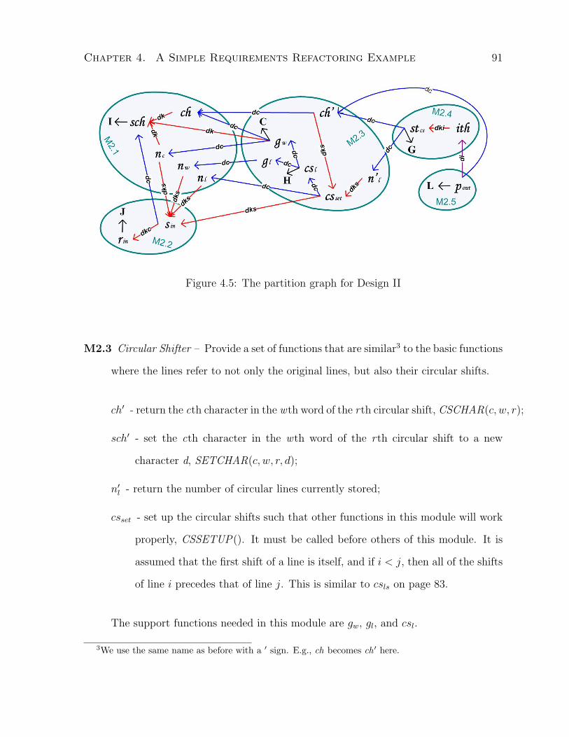
Chapter 4. A Simple Requirements Refactoring Example 91
Figure 4.5: The partition graph for Design II
M2.3 Circular Shifter – Provide a set of functions that are similar3 to the basic functions
where the lines refer to not only the original lines, but also their circular shifts.
ch′ - return the cth character in the wth word of the rth circular shift, CSCHAR(c, w, r);
sch′ - set the cth character in the wth word of the rth circular shift to a new
character d, SETCHAR(c, w, r, d);
n′l - return the number of circular lines currently stored;
csset - set up the circular shifts such that other functions in this module will work
properly, CSSETUP(). It must be called before others of this module. It is
assumed that the first shift of a line is itself, and if i < j, then all of the shifts
of line i precedes that of line j. This is similar to csls on page 83.
The support functions needed in this module are gw, gl, and csl.
3We use the same name as before with a ′ sign. E.g., ch becomes ch ′ here.

Chapter 4. A Simple Requirements Refactoring Example 92
M2.4 Alphabetizer – Provide two principle functions: ALPH (), to compute the order
of the circular shifts alphabetically (stcs); and,
ith - return the index of the circular shift which comes ith in the alphabetical
ordering.
M2.5 Output – Produce a desired printout of the lines or circular shifts (pout).
M2.6 Master Control – Sequence among the modules and handle exceptions and re-
source allocations.
The partition graph representing this design given in figure 4.5 shows improvements
have been made since the last design. First, the total multiplicity number has been
significantly reduced. Second, the coupling is restricted to just two cases: (i) between
M2.1 and M2.3, and (ii) between M2.2 and M2.3.
Implicit Invocation - Design III The third design alternative - Tool Abstraction
- proposed specifically to deal with changing requirements [GKN92]. This approach is
also known as Implicit Invocation [SG96]. It inherits from both of the two earlier designs
by using shared data with abstract types. The system is factored into four toolies,
Input, Circular Shift, Alphabetize, and Output, that are similar in functions to modules
in the earlier designs, but differ significantly in the ways of interaction. Each toolie
acts independently from others and is only invoked implicitly upon the occurrences of
interested events such as a specific change in the shared data. This approach aims at
decreasing the complexity of successive enhancements through the means of factoring the
system into independent entities that each focuses on a single function.
This design has the same partitions as design II (except M2.1 and M2.2 are merged
into one module), but implements the dependencies differently. In particular, the dc

Chapter 4. A Simple Requirements Refactoring Example 93
links are implemented through event invocation. This approach reduces the maintenance
work of the Master Control module over the data and sequential dependencies between
functions. We will not include this design in the discussion below since we expect it to
have the same results as design II.
Comparisons and Discussions
Parnas listed five decisions made in the above designs that are likely to change and used
them to articulate the importance of information hiding [Par72]. Here we review the five
points in the light of evaluating coupling and code/design reuse. Below, we refer to the
results (figure 4.3) obtained from our refactoring method as our design.
1. “Input format.”
Change in the input format directly affects function rin. In our design, sin may be
affected via a dk link and the change does not propagate further because gls only
cares about the storage mechanism (separate from the reading mechanism) via its
dk link to sin. This is also the case in design I and II.
In all cases, this change has a minimal impact as implementation changes may only
be required in one partition (module).
2. “The decision to have all lines stored in core. For large jobs it may prove inconve-
nient or impractical to keep all of the lines in core at any one time.”
Change regarding the storage mechanism directly affects function sin. In our design,
gls will be indirectly affected via the dk link causing design and implementation
change to one module. In design I, all of sc, sw, sl will be directly affected because
this decision is implemented in all these functions, and gls indirectly affected via
the dk link. The impact will also be propagated further via three dk links causing

Chapter 4. A Simple Requirements Refactoring Example 94
implementation change in every module. In design II, sch will also be directly
affected. Through the dk links, other functions in M2.1, and gw and csset from
M2.3 will also be affected. This causes implementation changes to three modules,
M2.1,M2.2, and M2.3.
This type of change has a major impact over design I, medium impact over design
II, and minimal impact over our design.
3. “The decision to pack the characters four to a word. In cases where we are working
with small amounts of data it may prove undesirable to pack the characters; time
will be saved by a character per word layout. In other cases we may pack, but in
different formats.”
This type of change is covered in dimension I and directly affects function sc and
sch. In our design, this also affects gc but is contained in one module. In design I,
gc is also affected, but since it is implemented in all modules, changes are required
in every module. In design II, ch is affected, but the change is contained in one
module (M2.1).
This change has a major impact over design I and minimal impact over both design
II and ours.
4. “The decision to make an index for the circular shifts rather than actually store
them as such. Again, for a small index or a large core, writing them out may be
the preferable approach.”
This change directly affects functions csls, csl and csset. In our design, gcs is indi-
rectly affected, and the impact is over two modules. In design I, gcs is indirectly
affected, and the impact is over modules M1.2 and M1.3. In design II, the impact
is contained in one module (M2.3) as the indirectly affected functions are ch′ and

Chapter 4. A Simple Requirements Refactoring Example 95
n′; however, the implementation effort is no less than the other two designs.
This change has about the same impact over all cases.
5. “The decision to alphabetize the list once, rather than either (a) search for each
item when needed, or (b) partially alphabetize ... In a number of circumstances
it would be advantageous to distribute the computation involved in alphabetization
over the time required to produce the index.”
Such a change directly impacts function stcs. In design I, although such a change
can be confined to function stcs in only module (M1.3), no time or effort can be
saved when only part of the items are needed because all the alphabetization have
been computed prior to this. To be able to distribute the computation on demand,
a substantial design change is required. In design II, with small changes to function
stcs, the existing design can easily support such a change and distributed computa-
tion. In our design, we have included such changes in the dimension L; thus, with
design and implementation change to pout, stcs and the dc link between them, we
can easily implement such a change via distributed computation on demand.
This change has a minimal impact over design II, a medium and manageable impact
over our design, and a major impact over design I.
This example shows that refactoring simplifies the design process in identifying ap-
propriate decomposition of the problem and generates a design that well observes the
low-coupling and high-cohesion principle. The resulting design is comparable to design
II which is well accepted.
However, the scope of applicability of this simple method is limited to low-level func-
tional requirements. In general, requirements are much more abstract, interdependent,
and sophisticated, especially for complex systems. In the following chapters, I will de-

Chapter 4. A Simple Requirements Refactoring Example 96
scribe a requirements refactoring theory and relevant methods for dealing with such
systems.
4.2 Insight to Requirements Refactoring
Based on the literature survey, empirical study, and the requirements refactoring ex-
ample, I define the following meaning and role of requirements refactoring in software
engineering.
4.2.1 Meaning of Requirements Refactoring
Refactoring is a technique employed to facilitate the subsequent development phases. For
example, program refactoring is used to make program maintenance easier, and design
refactoring is to make programming easier [Liu05]. By the same token, requirements
refactoring is to make design easier by revealing the structure embedded (or hidden) in
the problem.
Program refactoring is about restructuring without altering the external behavior of
the code. Design refactoring is similar except at a higher level of abstraction. This
cannot be applied to requirements refactoring because the behaviors have not necessarily
been determined, and it is the intent of the system that needs to be preserved. Thus,
requirements refactoring should be about determining the behavior without altering the
intent of the system.
Program and design refactoring are typically used after system is built; so it is a
reactive form of refactoring. But requirements refactoring is an active form of refactoring
since it should be performed before the system is built.
The problem with Parnas’ first solution to KWIC [Par72] is that the static (code)
structure was outlined before decomposition of the behavior was thought through. Thus

Chapter 4. A Simple Requirements Refactoring Example 97
the behavioral decomposition was highly restricted by the static structure and layout.
Behavioral decomposition needs to take changes into consideration, and static layout
should respect the behavioral decomposition and then optimize for reuse.
We may use requirements refactoring to determine the behavior and behavioral de-
composition, then apply design and program refactoring to optimize the static structure.
4.2.2 Role of Requirements Refactoring
Requirements specification is a contract (or agreement) between user and system de-
veloper. It cannot be used as a design substitute to coordinate the development work
between developers. It also may not have been organized or formulated in ways that are
easy to understand and manage. In many software development projects with moderate
or higher complexity, design is inevitable both as a management tool and a reference
model. Requirements refactoring is a tool for designers to understanding the require-
ments structure, and determine and deliver the design specification as a contract between
designer and implementers.
To this end, requirements refactoring cannot be in a “pure” form – one that only
manipulates structures of requirements. A pure form of requirements refactoring may
be interesting to a requirements engineer or analyst, but not to a designer. A mean-
ingful form of requirements refactoring to a designer needs to incorporate an element of
refinement towards design. Therefore, a useful requirements refactoring method should
provide a platform for design-related analysis based on requirements restructuring.
In the next chapter, I present a design theory that introduces a refactoring method
in a requirements refinement model.
Chapter 4. A Simple Requirements Refactoring Example 98
4.3 Summary
This chapter described a simple requirements refactoring method and how it is applied to
a familiar software engineering problem. Although the simple method may not apply to
general software development, it provides insight to the meaning and role of requirements
refactoring which leads to the definition of a more generic theory and method described
in the next chapter.
Chapter 5
Theory of Refactoring-based
Requirements Refinement
In this chapter, I present a novel design theory [Gre06] of refactoring-based requirements
refinement. The theory describes a requirements structuring and analysis approach in
moving from requirements to design. The theory gives specific meaning to the terms
requirements refinement, decomposition, and refactoring (§5.1), presents a refinement
process model [Liu08] that applies to requirements at four abstraction levels (§5.2), and
includes a refactoring method with a set of operators (transformations) and algorithms
applicable to requirements at different abstraction levels in the refinement process (§5.3).
For convenience purpose, I will refer to this theory as R3 (R-cube) theory and the
model (or framework) as R3 model (or framework).
5.1 Theory Constructs and Goal
This section defines the principal concepts of the theory, requirements refinement, de-
composition, and refactoring, and their relationship, and describes the goal, hypothesis,
99

Chapter 5. Theory of Refactoring-based Requirements Refinement 100
and falsifiability of the theory. The model (framework) and method of the theory are
presented in the subsequent sections.
5.1.1 Principal Concepts and Relationship
The theory defines three principal concepts, requirements refinement, refactoring, and
decomposition, and their relationship as follows.
Requirements Refinement
In the surveyed literature presented in Chapter 2, we can see that the term “refinement”
is used to refer to three distinct meanings: product, method (or actions, means), and
process. As product, it can refer to both the relationship or the end product of the
means of refinement. For example, goal-based AND- and OR-refinement links are such
relationships, and the goals following such links are the refinement products [DvLF93].
As method, it is used as means to define refinement relationships such as goal refinement
patterns [DvL96]. As process, it is thus far used to bridge the gap between requirements
and specifications [ZJ97].
In R3 theory, requirements refinement is specifically used to refer to the process,
or action flow, that guides the actions in moving from requirements space to design
space. A model (framework) is presented in Section 5.2 describing a specific requirements
refinement process.
Definition 5.1 (Requirements Refinement) Requirements refinement is a process
that guides the application of appropriate methods (such as refactoring) in converting
high-level abstract requirements into requirements decompositions and specifications while
design perspectives are considered.

Chapter 5. Theory of Refactoring-based Requirements Refinement 101
Requirements Refactoring
The term “refactoring” has not been defined in the requirements context in the literature
as seen in Chapter 2. In the wider software engineering context, refactoring is defined to
be a restructuring process mainly used to improve internal structure [Opd92, GHJV95,
TB99]. In R3 theory, requirements refactoring is defined as below.
Definition 5.2 (Requirements Refactoring) Requirements refactoring is a method
in a refinement process that provides a platform in guiding analysis towards revealing re-
lationships between requirements, structuring complex requirements into decoupled parts,
and simplifying and completing requirement descriptions.
Requirements Decomposition
The term “decomposition” is used in the literature to refer to both the method of decom-
posing requirements (breaking complex problems into smaller pieces) [DvLF93, CNYM00,
Yu95] and the end product (subproblems as a result of decomposing) [NF92]. The prob-
lem frames work [Jac01] uses the term in both senses as it provides problem patterns
(as decomposition product) and heuristics for breaking down a problem (as decomposing
method).
Decomposition is one form of refinement products. There are other forms of re-
finement products such as operationalization and argumentation in the refinement of
non-functional requirements [CNYM00]. In R3 theory, we are only concerned with the
decomposition form of refinement product. The term requirements decomposition is
specifically used to refer to the end product of each application of refactoring method in
the provided requirements refinement process.
Definition 5.3 (Requirements Decomposition) Requirements decomposition is a
collection of components consisting the requirements and their dependencies resulted in

Chapter 5. Theory of Refactoring-based Requirements Refinement 102
applying requirements refactoring methods in the defined requirements refinement process.
Relationship
The relationship between requirements refinement, refactoring, and decomposition is the
following: refinement is a process that includes refactoring methods which produces
decompositions as results.
5.1.2 Goal of the Theory
As Jackson indicates, a clear understanding of the requirements (or the problem) is crucial
in building useful systems, and to allow successful evolution, its design must reflect the
structure of the problem [Jac96]. TheR3 theory is designed to help designers to reveal the
underlying structure of the problem in a requirements refinement process. Furthermore,
the refactoring method of the theory allows designers to analyze dependency relations
(including overlap and redundancy) between requirements and decompose requirements
through refactoring transformations. The method is defined within the refinement process
where algorithms of which transformations to apply are defined. The process produces
a requirements decomposition, candidate design, that resembles a system decomposition
which designers can use as a draft design. Subsequent design artifacts built on this
platform inherits the structure, thus reflecting the structure of the problem.
The hypothesis of the theory is:
Given high-level system requirements (including system goals and intent),
the refinement process and refactoring method of R3 theory provide a plat-
form for designers to carry out analysis to simplify requirements descriptions,
remove redundancy, uncover dependencies, extract lower-level requirements,
incorporate design concerns, and produce a system decomposition observing

Chapter 5. Theory of Refactoring-based Requirements Refinement 103
the dependencies between requirements in well-guided small steps with visible
progress. A design built on top of the resulting system decomposition inherits
the structure of the problem (defined by the requirements). This approach
should reduce effort spent by designers performing similar tasks without a
systematic approach in coming up with a design that reflects the structure of
the problem.
A theory, differing from a belief, must be falsifiable. To show that R3 theory is
falsifiable, we can set up an empirical study as the following. Hire two designers with the
same set of skills, training, experience, and background. Give both designers the same
set of requirements to build an initial design (system decomposition) of the same system.
Have one to apply the R3 theory and the other to use an ad hoc approach. Compare the
results to make sure the same quality is achieved. Measure the effort spent in the design
process. If the theory should not hold, the designer using the ad hoc approach would
spend less effort.
The R3 theory is a form of design and action theory according to Gregor’s taxonomy
[Gre06], and is summarized in Table 5.1.
5.2 Refinement Model (Framework)
There are three main components to the model (or framework): designer vs. user stance,
requirements abstraction levels, and refinement phases. Six refinement phases are defined
within four abstraction levels where designer and user perspectives are separately ana-
lyzed in the middle two levels. Figure 5.1 shows a conceptual model of the framework.
The junction points in Figure 5.1 are where the refactoring method is applied. Figure
5.2 defines the metamodel of the constructs in the refinement process and refactoring
method.
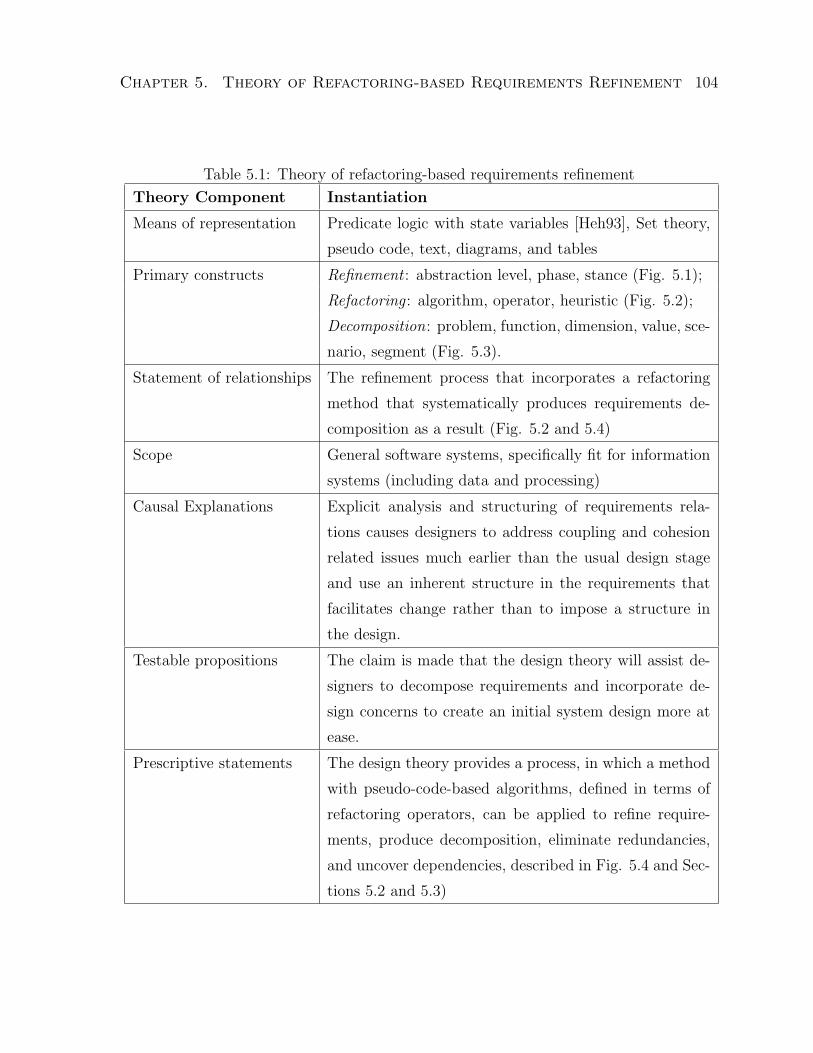
Chapter 5. Theory of Refactoring-based Requirements Refinement 104
Table 5.1: Theory of refactoring-based requirements refinement
Theory Component Instantiation
Means of representation Predicate logic with state variables [Heh93], Set theory,
pseudo code, text, diagrams, and tables
Primary constructs Refinement : abstraction level, phase, stance (Fig. 5.1);
Refactoring : algorithm, operator, heuristic (Fig. 5.2);
Decomposition: problem, function, dimension, value, sce-
nario, segment (Fig. 5.3).
Statement of relationships The refinement process that incorporates a refactoring
method that systematically produces requirements de-
composition as a result (Fig. 5.2 and 5.4)
Scope General software systems, specifically fit for information
systems (including data and processing)
Causal Explanations Explicit analysis and structuring of requirements rela-
tions causes designers to address coupling and cohesion
related issues much earlier than the usual design stage
and use an inherent structure in the requirements that
facilitates change rather than to impose a structure in
the design.
Testable propositions The claim is made that the design theory will assist de-
signers to decompose requirements and incorporate de-
sign concerns to create an initial system design more at
ease.
Prescriptive statements The design theory provides a process, in which a method
with pseudo-code-based algorithms, defined in terms of
refactoring operators, can be applied to refine require-
ments, produce decomposition, eliminate redundancies,
and uncover dependencies, described in Fig. 5.4 and Sec-
tions 5.2 and 5.3)
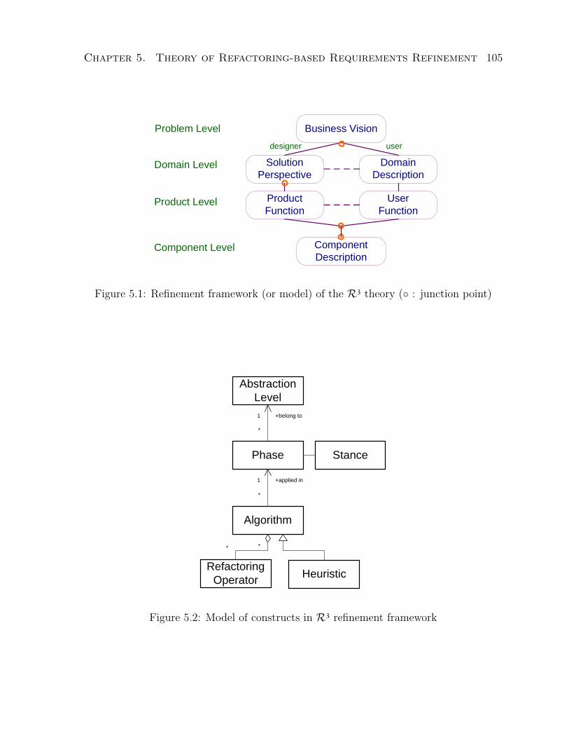
Chapter 5. Theory of Refactoring-based Requirements Refinement 105
Problem Level
Domain Level
Product Level
Component Level
designer user
Domain Description
UserFunction
Solution Perspective
Product Function
Business Vision
Component Description
Figure 5.1: Refinement framework (or model) of the R3 theory (◦ : junction point)
Algorithm
RefactoringOperator
AbstractionLevel
Heuristic
Phase Stance
+applied in1
*
+belong to1
*
**
Figure 5.2: Model of constructs in R3 refinement framework

Chapter 5. Theory of Refactoring-based Requirements Refinement 106
5.2.1 Designer versus User Stance
Requirements represent a contract (or agreement) between user and system developer
and the system should be built to serve the users in ways specified in the requirements.
However, the process of building the system largely concerns the developer and designer.
As requirements refinement is part of this process, the designer perspectives must be
explicitly considered. In both the literature and practice, designer concerns are seldomly
made explicit. In R3 framework, designer and user concerns are separately analyzed in
two abstraction levels. Since it is, in general, hard to distinguish design decisions from
user requirements a posteriori, when changes are received during or after the system con-
struction, less optimal or conflicting decisions may be made due to the lack of knowledge
of earlier decisions. The separate analysis documenting design concerns and user needs
provides easier traceability for later updates. In addition, design decisions should be
made to support the satisfaction of user requirements; they should not compromise the
user goals.
5.2.2 Requirements Abstraction Levels and Refinement Phases
Four abstraction levels are defined to structure the requirements refinement process from
high-level business goals down to individual requirements specifications with dependen-
cies between them explicitly marked. The first two levels focus on the business goals, and
the last two focus on requirements specifications. These abstraction levels are inspired
from those described by Svetinovic in architectural use cases [Sve03].
Problem Level
As the most abstract level, the business level is designed to handle high-level business
requirements. Such requirements can be the purpose, intentions, and business interests

Chapter 5. Theory of Refactoring-based Requirements Refinement 107
towards the system-to-be. They often provide the general contextual information that
is necessary to derive any missing detail or resolve conflicts at lower levels. In general,
requirements at this level tend to be abstract and may be expressed as expectations for
current limitations or business goals to be achieved by using the system-to-be.
The goal of business-level requirements refinement is to remove redundant descriptions
among the business goals and to form a problem decomposition that partitions the goals
based on their dependency relations.
One refinement phase, Business Vision Phase , is defined where a business vision,
represented by a collection of business needs described in text, is given. The vision
conveys current business problems, limitations and impact, and expectations from a
software solution. In later sections, business needs and problems are used interchangeably
to refer to the business vision or goals.
Domain Level
At the domain level, domain knowledge, system environment, design concerns, and user
needs are factored into the refinement process. The designer and user stance are analyzed
separately in two phases.
The Solution Perspective Phase takes the designer perspective of the system us-
age and focuses on the static aspects involving structure and layout. It can be considered
a macro view of the overall system usage. The abstract problems expressed in the prob-
lem decomposition are refactored to take into account of design concerns in obtaining a
solution decomposition.
The Domain Description Phase takes the user perspective of the system usage
and focuses on the dynamic aspects involving expected interaction and behavior. It can
be considered as a micro view of the individual usage with respect to user tasks. The
expected user-oriented business context is described in a domain description referencing

Chapter 5. Theory of Refactoring-based Requirements Refinement 108
the problem decomposition. The description includes end-to-end tasks users perform with
the assistance of the system-to-be, collaborations between users while using the system,
and business flows. Scenarios are the recommended representation of the description
because it is well recognized in requirements engineering that scenarios are an effective
way in eliciting user requirements.
Generally, the two refinement phases can be carried out in parallel. However, the
domain description can be made more structured when it is based on the layout of the
solution perspective. This introduces a dependency and iterative process between the
two phases.
Product Level
Functions (requirements specifications) are extracted from the domain-level descriptions
included in the solution decomposition and domain description. These functions are
refined towards a product decomposition in two phases.
In the Product Function Phase , specific functions are extracted from the solution
decomposition and problem descriptions. These functions are mainly system-side func-
tions or support functions for user-facing functions. They may include user functions
that are not extracted from the domain description in the User Function Phase but can
be deduced from the solution decomposition.
In the User Function Phase , functions that users invoke directly in the system
are extracted from the domain description and problem descriptions.
All functions are then assigned to responsible components.
Each phase is an extension of its counterpart from the level above. However, it is
recommended to start from the user perspective and extract user functions, then move
to the designer perspective and extract remaining product and/or user functions. This
is because the support (product) functions can be more easily defined once the user

Chapter 5. Theory of Refactoring-based Requirements Refinement 109
functions are present. Furthermore, the domain description is represented in a stepwise
fashion making it easy to extract user functions. In addition, functions that are missed
from the domain description can be recouped in the Product Function Phase. This is often
unnecessary if the domain description is created referencing the solution decomposition
in the previous level. When both phases are carried out, we obtain a complete product
decomposition.
Component Level
In this level, the designer and user stance are no longer separated. The refinement
focuses on removing redundant functions, resolving functional dependencies, simplifying
and generalizing function definitions. One refinement phase is defined.
The Component Description Phase aims at improving the functional descrip-
tions by examining the dependencies between functions, reducing overlap between func-
tions, and extracting new prime functions from interface functions. A component decom-
position is produced as a result where component responsibilities and dependencies are
specified by the functions and their dependency relations.
5.3 Refactoring Method
The R3 refactoring method consists of a set of operators and algorithms applicable to re-
quirement artifacts of different abstraction levels in constructing a system decomposition.
The final system decomposition obtained is called a candidate design.
In this section, I present the definitions, refactoring operators and properties, the
refactoring algorithms and analysis on complexity, and a discussion on human factors,
intent preservation, and non-functional requirements relating to the method.

Chapter 5. Theory of Refactoring-based Requirements Refinement 110
typeidrankdescription
Problem
nameSegment
segments
*
problems
*
Dimension
Value
dimension1
values*
typeiddescription
FunctionScenario scenarios
*
functions
*
problems
*
functions
*
scenarios
*
problems
*
*
value
0..1
dependees *
dependents
*
segments *
functions
*
Figure 5.3: Definition of terms and relationships in R3 theory (state constants are in
grey)
5.3.1 Definitions
The principal constructs are problem, function, scenario, and dimension. Segment is an
artifact created by the method. Figure 5.3 illustrates the model of all the terms and their
relationship in the refactoring method.
Definition 5.4 (Principal Constructs)
A problem describes a specific high-level problem/challenge (business requirement)
that is to be solved or improved via the system-to-be. It has attributes: id, type (prime
or interface), description (summary), details (optional; may include issue, impact, and
desired solutions).
A function describes a functional specification to be implemented by the system-to-be
in resolving the problems.
A scenario describes an end-to-end task users perform using system-to-be, collabora-
tions between users while using the system-to-be, or an end-to-end business process the
system-to-be is expected to enforce a part.
A dimension describes a design concern that may reveal further coupling and cohesion

Chapter 5. Theory of Refactoring-based Requirements Refinement 111
properties between problems and affect the decomposition of the system-to-be. It comprises
a collection of orthogonal values that completely covers the design concern. Two values
are orthogonal if they represent independent considerations in the dimension which may
reveal decoupling properties between problems.
A problem is similar to a high-level goal or operational functional requirement defined
by van Lamsweerde in [vL03] or requirement defined by Jackson in [Jac97]. Here are two
examples of problems: (a) “Need a web-hosted means for communication between people
in place of face-to-face meeting or telephone-based conversations”; and (b) “Share data
online”.
A prime problem describes a responsibility that must be implemented in the system-
to-be; an interface problem specifies a dependency relation (or interaction) between two
prime problems of different components. The default type of a problem is prime.
The aforementioned problem examples are prime problems. An example of an in-
terface problem is: “Authenticate before using on-line data sharing facilities” where the
interaction starts from the source end (on-line data sharing facilities component) to the
target end (authentication component).
The term function is similar to the term specification defined by Jackson in [Jac97].
Functions can be described in terms of Use Cases [BRJ00]. For example, we can define
a few use cases from the above problem example as: “Join an on-going web meeting”,
“Start a new web meeting”, and “End the current web meeting”. A function is identified
as dependent if its implementation depends on another function which serves as either
a precondition, generalization, extension, or inclusion [BRJ00]. For example, the above
use cases require the following use case as a precondition: “Authenticate successfully”.
Dimensions are defined to capture design concerns (cross-cutting) that affect multiple
requirements and make the system decomposition non-straightforward. For example,

Chapter 5. Theory of Refactoring-based Requirements Refinement 112
the dimension “protect against unauthorized usage” is relevant to the prime problems
given above. The values of this dimension can be defined as “protection needed” and
“protection not needed”. These two values make up the protection dimension since they
completely cover the protection concern; and they are orthogonal because they cannot
be simultaneously assigned to any problem.
Often, requirements are specified in an imprecise manner where additional interpreta-
tion and description is required before further refinement can be done. For example, the
requirement “Easy to backup data” in which the data is not clearly defined. It could mean
all possible types of data or just a few specific types. Before all requirements are acquired,
it can be hard to determine which is the case. When all the requirements are acquired, it
is tedious to update all the reference points to reflect the more precise meaning of “data”.
In cases like this, it is incumbent on the designer to analyze all requirements to ensure the
term “data” is updated precisely to reflect the intended meaning. Using the R3 method,
designers may choose to define a dimension to represent this requirement and postpone
the analysis which data types require backup to the domain-level refactoring. However,
designers may also assume that “data” refers to all types of data and simply treats this
requirement as a problem like all others and apply the method as prescribed. This is
simply a choice of style. As long as the choice is made consistently, the repeatability of
the method will not be affected.
It is easy to define a dimension that is a bi-partite or corresponds to a design concern
that is covered by naturally orthogonal values as the preceding example shows. Defining
a dimension for a design concern that is covered by values which are not orthogonal
may seem non-trivial, but only requires a little extra work – to use the power set of the
design concern values as the values for the dimension. The members of the power set are
orthogonal according to the above definition.

Chapter 5. Theory of Refactoring-based Requirements Refinement 113
Definition 5.5 (Artifacts)
Segment is created by the refactoring method for ease of reference to problems and
functions that exhibit a close relationship (cohesion) and share common characteristics.
Ultimately, it represents a system component in the decomposition of the system-to-be. It
has an attribute: name.
Continuing with the web-based communication and data sharing tool example, we
may get the following segments: logon, text message, video conference, data transfer,
data stream, address book, and history record.
A segment is often implemented as a component of the system-to-be. The problems
and functions assigned it describe the responsibilities of the segment (or component). A
segment also holds references to dependent functions of its member functions.
Definition 5.6 (State) Assume each object in the state space has an implicit unique
attribute, id, which is a state constant.
The state space of the refactoring method has the following variables.
• S is the set of segments (a.k.a partition).
• P is the set of problems.
• F is the set of functions.
• SP is the set of related segment-problem pairs.
• SF is the set of segment-function pairs related by association.
• PF is the set of related problem-function pairs.
• FD is the set of dependent-dependee pairs of functions.
The state constants include the following: C is the set of scenarios; D is the set
of dimensions; CP is the set of related scenario-problem pairs; CF is the set of related
scenario-function pairs.

Chapter 5. Theory of Refactoring-based Requirements Refinement 114
In a non-trivial application of the method, the initial state should begin with P0 6=
∅, PF0 = ∅, SP0 = ∅, SF0 = ∅, and FD0 = ∅.
The state after problem-level refactoring is called a problem decomposition, after
domain-level refactoring is called a solution decomposition, after product-level refactor-
ing is called a product decomposition, and after component-level refactoring is called a
component decomposition.
The final state is called a candidate design.
The following references, defined in Figure 5.3, are used to select items in the relations
of the sate space.
• Segment.problems: the set of problems associated to a segment.
• Segment.functions: the set of functions associated to a segment.
• Segment.dependents: the set of dependent functions of the functions associated to
a segment.
• Segment.value: the dimension value associated to a segment.
• Problem.segments: the set of segments a problem is associated to.
• Problem.sourceSegment: the source (dependent) segment of a problem of interface
type.
• Problem.destSegment: the destination (dependee) segment of a problem of interface
type.
• Problem.functions: the set of functions that is deduced from a problem.
• Function.segments: the set of segments a function is associated to.

Chapter 5. Theory of Refactoring-based Requirements Refinement 115
• Function.problems: the set of problems that a function is induced from.
• Function.depSegments: the segments containing dependee functions of a function.
• Function.dependees: the set of functions that a function depends on.
• Function.dependents: the set of dependent functions to a function.
• Function.scenarios: the set of scenarios that is associated to a function.
• Scenario.problems: the set of problems associated to a scenario.
• Scenario.functions: the set of functions associated to a scenario.
• Dimension.values: the set of values a dimension comprises.
• Value.dimension: the dimension that a value is part of.
• For convenience, we use x.segment to represent x.segments[0] when it is clear that
there is exactly one segment in the collection.
Definition 5.7 (Terms for Convenience)
The rank of a problem is the number of distinct segments it belongs to. A problem is
spanning if its rank is greater than 1.
5.3.2 Refactoring Operators
An operator is a transformation of the state space, expressed as a relation between pre-
and poststate. There are 16 kinds of transformations, each parameterized by a tuple,
called the selector, expressing a choice of a particular small part of the state space to be
refactored.
Every operator is total – if its selector does not exist in the current state or its
precondition is not met, then the state is left unchanged.

Chapter 5. Theory of Refactoring-based Requirements Refinement 116
In the following definitions, = is used as equality, not assignment. We follow the
convention that for a state variable x, its prestate value is x and its poststate x′ [Heh93].
When referring to a member problem p of P , we use the identifier p to index the set P ,
i.e., p = Pp . To indicate change in p’s attribute, say p.type changes to prime, we use
P ′p.type = prime. Same applies to S and F .
Partition: ptn(d : dimension)
Precondition: S = ∅ ∧ d ∈ D
For each value vi of d, create a segment si with si.name = vi and si.value = vi.
S ′ = {si}
Purpose: To establish a set of segments corresponding to the values of the given
dimension. These segments will be used to partition problems through association.
Consolidate: con(a : segment ; b : segment)
Precondition: a.problems ⊆ b.problems ∧ (a and b do not warrant separate
components in the system-to-be)
Remove a. Let h(x; y) be a function that returns a name based on the input two
segments. Update b.name to h(a; b).
S ′ = S r {a}
S ′b.name = h(a; b)
Purpose: To remove a segment that is already represented.
Split Problem: spp(p : problem)
Precondition:

Chapter 5. Theory of Refactoring-based Requirements Refinement 117
p.rank > 1
∧ p.type = prime
∧ ∀ 〈x; y〉 ∈ PF · (p 6= x)
∧ ∀ 〈x; y〉 ∈ CP · (p 6= y)
Split p into a set of new subproblems {pi}, such that each pi describes the part
of p that concerns segment si, for every si ∈ p.segments. The subproblems {pi}
should be complete and sound, and their identifiers be distinct and descriptions
be as disjoint as possible (but overlaps are permitted if unavoidable). For each i,
replace 〈si; p〉 with 〈si; pi〉 in SP .
P ′ = P ∪ {pi}r {p}
SP ′ = SP ∪ {〈si; pi〉}r {〈si; p〉}
Purpose: To eliminate overlaps of associated prime problems between segments.
Assign Problem: asp(t : type; p : problem; s : segment)
Precondition: (t = prime ∨ t = interface) ∧ p.segments = ∅
Assign p to type t and associate to s.
P ′p.type = t
SP ′ = SP ∪ {〈s; p〉}
Purpose: To associate problem to segment either as prime or interface. The asso-
ciation between problems and segments represents problem partitioning.
Merge: mrg(B : {problem}; s : segment)
Let B = {pi}.
Precondition:
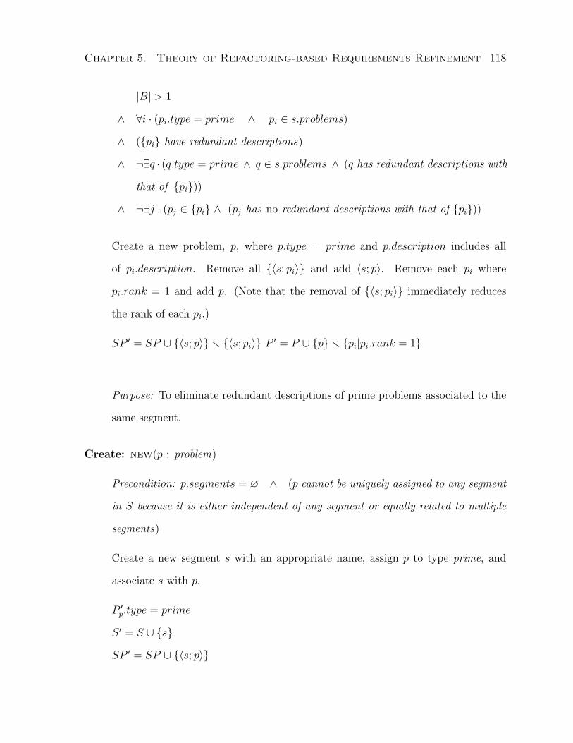
Chapter 5. Theory of Refactoring-based Requirements Refinement 118
|B| > 1
∧ ∀i · (pi.type = prime ∧ pi ∈ s.problems)
∧ ({pi} have redundant descriptions)
∧ ¬∃q · (q.type = prime ∧ q ∈ s.problems ∧ (q has redundant descriptions with
that of {pi}))
∧ ¬∃j · (pj ∈ {pi} ∧ (pj has no redundant descriptions with that of {pi}))
Create a new problem, p, where p.type = prime and p.description includes all
of pi.description. Remove all {〈s; pi〉} and add 〈s; p〉. Remove each pi where
pi.rank = 1 and add p. (Note that the removal of {〈s; pi〉} immediately reduces
the rank of each pi.)
SP ′ = SP ∪ {〈s; p〉}r {〈s; pi〉} P ′ = P ∪ {p}r {pi|pi.rank = 1}
Purpose: To eliminate redundant descriptions of prime problems associated to the
same segment.
Create: new(p : problem)
Precondition: p.segments = ∅ ∧ (p cannot be uniquely assigned to any segment
in S because it is either independent of any segment or equally related to multiple
segments)
Create a new segment s with an appropriate name, assign p to type prime, and
associate s with p.
P ′p.type = prime
S ′ = S ∪ {s}
SP ′ = SP ∪ {〈s; p〉}

Chapter 5. Theory of Refactoring-based Requirements Refinement 119
Purpose: To create a new segment so that the given problem can be uniquely
associated to.
Extract: xtr(B : {problem})
Let B = {pi}.
Precondition:
|B| > 1
∧ ∀i · (pi.rank = 1 ∧ pi.type = prime)
∧ ∀p ∈ B · ∀ 〈x; y〉 ∈ PF · (p 6= x)
∧ ∀p ∈ B · ∀ 〈x; y〉 ∈ CP · (p 6= y)
∧ ¬∃q ∈ P · (q.type = prime ∧ q.rank = 1 ∧ (q shares the same subproblem))
∧ (all problems in B share a common subproblem)
Extract the common subproblem into a new prime problem p, and for each pi, (i)
define an interface problem qi that indicates the dependency on p in fulfilling pi and
associate qi to si; and (ii) update the description of pi to exclude the subproblem
represented by p, and if pi has a trivial description, remove pi and 〈si; pi〉.
Let f(x) be a function that updates description of problem x to exclude subproblem
p.
P ′ = P ∪ {p} ∪ {qi} ∪ {y|y ∈ f{pi} ∧ (y.description is not trivial)}r {pi}
SP ′ = SP∪{〈si; qi〉}∪{〈si; y〉 |y ∈ f{pi} ∧ (y.description is not trivial)}r{〈si; pi〉}
Purpose: To eliminate common subproblem between prime problems associated
to different segments, i.e., to eliminate semantic overlaps between segments with
respect to their associated prime problems.
Update: upd(s : segment)
Precondition: none

Chapter 5. Theory of Refactoring-based Requirements Refinement 120
Update s with a descriptive name to reflect the characteristics of its associated
prime problems.
Let g(x) be a function that updates name of segment x to reflect the characteristic
of its prime problems.
S ′s.name = g(s)
Purpose: To update segment’s name to reflect the characteristics of its associated
prime problems.
Generate: gen(s : segment)
Precondition: the prime problems of s do not cover all relevant CRUD (create,
read, update, delete) aspects with respect to s.value
Define new prime problems {pi} to cover the left-out aspect(s) with respect to
s.value. Associate {pi} to s for each i.
P ′ = P ∪ {pi}
SP ′ = SP ∪ {〈s; pi〉}
Purpose: To generate missing prime problems given a segment.
Establish: est(s : segment ; v : dimension.value)
Precondition: v 6= ⊥ ∧ s.value = v
∧ ¬∃p ∈ s.problems · (p.type = prime ∧ (p.description covers the concern
represented by v))
Define a prime problem p that indicates the concern represented by v with respect
to dimension v.dimension and segment s. Associate p to s.
P ′ = P ∪ {p}
SP ′ = SP ∪ {〈s; p〉}

Chapter 5. Theory of Refactoring-based Requirements Refinement 121
Purpose: To define new prime problem in describing the concern represented by a
dimension value in the context of a given segment.
Divide: div(s : segment ; d : dimension)
Precondition: s.value 6∈ d.values ∧ ∀ 〈x; y〉 ∈ SF · (s 6= x)
For each prime problem p ∈ s, associate p to the most relevant values in d.values.
Group the problems according to their values {v0, . . . , vn} and getG = {G0, . . . , Gn}
where each Gi is a group of problems associated to vi and n 6 (|d.values| − 1).
If |G| > 1, divide segment s into separate segments {s0, . . . , sn} such that each si
is associated to all problems in the respective Gi and dimension value vi. Name si
to include both s.name and vi. Re-associate the existing interface problems in s to
the new segments {si} respectively. Remove s.
S ′ = S ∪ {si}r {s}
∀p ∈ s.problems · (〈s; p〉 6∈ SP ′ ∧ ∃i · 〈si; p〉 ∈ SP ′)
Purpose: To divide up a segment that covers multiple values of a dimension through
its associated problems. The dimension values represent decoupling conditions.
Realize: rlz(f : function; p : problem)
Precondition: p 6∈ f.problems ∧ (f contributes to the realization or implemen-
tation of p)
Associate f to p.
PF ′ = PF ∪ {〈p; f〉}
Purpose: To associate function to problem where at least a part of the problem is
realized by the function.
Assign Function: asf(f : function; s : segment)
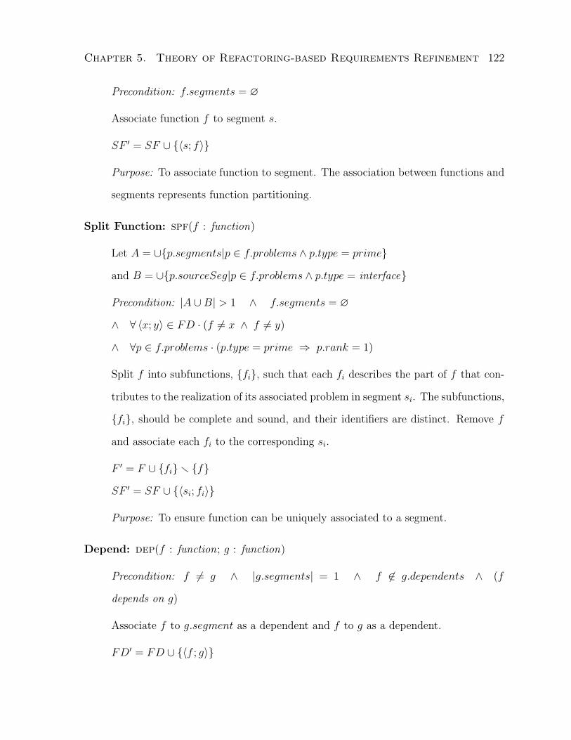
Chapter 5. Theory of Refactoring-based Requirements Refinement 122
Precondition: f.segments = ∅
Associate function f to segment s.
SF ′ = SF ∪ {〈s; f〉}
Purpose: To associate function to segment. The association between functions and
segments represents function partitioning.
Split Function: spf(f : function)
Let A = ∪{p.segments|p ∈ f.problems ∧ p.type = prime}
and B = ∪{p.sourceSeg|p ∈ f.problems ∧ p.type = interface}
Precondition: |A ∪B| > 1 ∧ f.segments = ∅
∧ ∀ 〈x; y〉 ∈ FD · (f 6= x ∧ f 6= y)
∧ ∀p ∈ f.problems · (p.type = prime ⇒ p.rank = 1)
Split f into subfunctions, {fi}, such that each fi describes the part of f that con-
tributes to the realization of its associated problem in segment si. The subfunctions,
{fi}, should be complete and sound, and their identifiers are distinct. Remove f
and associate each fi to the corresponding si.
F ′ = F ∪ {fi}r {f}
SF ′ = SF ∪ {〈si; fi〉}
Purpose: To ensure function can be uniquely associated to a segment.
Depend: dep(f : function; g : function)
Precondition: f 6= g ∧ |g.segments| = 1 ∧ f 6∈ g.dependents ∧ (f
depends on g)
Associate f to g.segment as a dependent and f to g as a dependent.
FD′ = FD ∪ {〈f ; g〉}

Chapter 5. Theory of Refactoring-based Requirements Refinement 123
Purpose: To define dependence relations between functions and segments.
Generalize: gnr(s : segment)
Precondition: (there is need for generalization over s.functions) ∨ (variability is
detected among s.dependents for any specific dependency)
Generalize among s.functions to simplify functional definitions, and analyze the
variability1 among s.dependents to separate out different types of dependence a
depended function supports. Define new functions hi as results of the generalization
and variability analysis to replace the original functions {fi} ⊆ s.functions, and
update the dependencies among the relevant functions.
F ′ = F ∪ {hi}r {fi}
SF ′ = SF ∪ {〈s;hi〉}r {〈s; fi〉}
∀i · ∀g ∈ fi.dependents · (〈g; fi〉 6∈ FD′ ∧ ∃j · 〈g;hj〉 ∈ FD′)
∀i · ∀g ∈ fi.dependees · (〈fi; g〉 6∈ FD′ ∧ ∃j · 〈hj; g〉 ∈ FD′)
Purpose: To define new functions via generalization and variability analysis over
functions associated to the same segment and their dependents in simplifying the
overall functional descriptions.
5.3.2.1 Properties of Operator Composition
Three important algebraic properties of the composition of above operators are discussed
below: idempotence, associativity, and commutativity.
Let f(x) be a refactoring operator with a selector x. Given an instance selector a, f(a)
is a (parameterized) transformation between states. Given a pair of states, σ (prestate)
1Given a function f , analyze the differences (variability) in its dependence relations with its dependentfunctions. The purpose is to differentiate the varied needs and support required by the dependentfunctions of f . It is later referred to as the variability analysis.

Chapter 5. Theory of Refactoring-based Requirements Refinement 124
and σ′ (poststate), for each transformation f(a), we can define a boolean function f(a)σσ′
such that f(a)σσ′ = > iff f(a) is a transformation from prestate σ to poststate σ′.
The composition of operators is sequential and each operator is parameterized, e.g.,
f(x) ; g(y). Let σ be the initial state, and σ′ be the final state. We define
f(x) ; g(y) applied in state σ and results in state σ′
= (f(x) ; g(y))σσ′
= ∃σ′′ · f(x)σσ′′ ∧ g(y)σ′′σ′
Recall every operator is total, i.e., if its selector does not exist in the current state or
its precondition is not met, the state is left unchanged. Let ok denote the operator that
leaves the state unchanged.
Let X and Y be two expressions formed by composition of operators. We define the
equivalence relation (=) between them as
X = Y iff ∀σ, σ′ ·Xσσ′ = Yσσ′
Idempotence
State transformations are defined with respect to parameterized operators. Operators
formed under different parameterization are treated as distinct state transformations.
Therefore, idempotence is only defined when an operator is parameterized with the same
selector instance. Under this definition, all operators are idempotent. Let f(x) denote a
parameterized operator,
f(x) ; f(x) = f(x)
The proofs of the operators being idempotent fall under three cases.
• Precondition fails at the second application which acts like ok.
This case includes ptn, asp, new, gen, est, div, rlz, asf, dep, gnr.

Chapter 5. Theory of Refactoring-based Requirements Refinement 125
• The selector does not exist in the state at the second application which acts like
ok.
This case includes con, spp, mrg, xtr, spf.
• No semantic change in the state.
This case includes upd (assuming function g(x) is consistently defined during re-
peated applications of upd).
Associativity
All operator compositions are associative.
Let f, g, and h be three parameterized operators. For any pre- and poststate pair,
〈σ;σ′〉, by definition, we get
((f ; g) ; h)σσ′
= ∃σ′′ · (f ; g)σσ′′ ∧ hσ′′σ′
= ∃σ′′ · (∃σ0 · fσσ0 ∧ gσ0σ′′) ∧ hσ′′σ′
= ∃σ′′∃σ0 · fσσ0 ∧ gσ0σ′′ ∧ hσ′′σ′
(f ; (g ; h))σσ′
= ∃σ0 · fσσ0 ∧ (g ; h)σ0σ′
= ∃σ0 · fσσ0 ∧ (∃σ′′ · gσ0σ′′ ∧ hσ′′σ′)
= ∃σ0∃σ′′ · fσσ0 ∧ gσ0σ′′ ∧ hσ′′σ′
= ∃σ′′∃σ0 · fσσ0 ∧ gσ0σ′′ ∧ hσ′′σ′
= ((f ; g) ; h)σσ′
We say f ; g ; h is associate and have
f ; g ; h = (f ; g) ; h = f ; (g ; h)

Chapter 5. Theory of Refactoring-based Requirements Refinement 126
Commutativity
Operator composition of different types is, in general, not commutative. However, this
does not affect the repeatability2 (consistency of results) of the method as operators of
different types are composed in specific sequential orders in the refactoring algorithms.
However, the commutativity of operator compositions of the same type may affect the
repeatability.
In the remainder of this dissertation, we say an operator is commutative iff a com-
position of only its type of operators under different parameterization is commutative.
Given that the analysis is not part of the method (or operators), we discuss the
commutativity property under the assumption that analysis is applied consistently by
the designer.
Operators ptn, con, mrg, xtr, div, and gnr are not commutative.
Operators spp, asp, new, upd, gen, est, rlz, asf, spf, and dep are partially com-
mutative under the assumption that (~) the selector exists and precondition is satisfied
in the prestate.
The proof of spp is shown below. The other ones can be proved similarly.
Proof of spp commutes under assumption ~:
Let 〈σ;σ′〉 be any pre- and poststate pair and assume ~.
Let P and SP denote the state variables in σ, LHS = spp(p) ; spp(q), and RHS =
spp(q) ; spp(p).
Assume p 6= q. (Otherwise, LHSσσ′ = RHSσσ′ by idempotence.)
In LHS, applying spp(p) changes state σ to an intermediate state, say σ′′l , containing
the following changes:
2The repeatability is limited to the scope of the method applied by the same designer. See Sections5.3.4.1 and 7.1.1 for further discussions.

Chapter 5. Theory of Refactoring-based Requirements Refinement 127
P ′′l = P ∪ {pi}r {p}
SP ′′l = SP ∪ {〈si; pi〉}r {〈si; p〉}
By assumptions, p 6= q, q ∈ σ, and the precondition of spp(q) is satisfied in σ,
therefore, q ∈ σ′′l and the precondition of spp(q) is satisfied in σ′′l since no change is made
with respect to q in the above transformation.
Then, applying spp(q) in state σ′′l changes the state to, say σ′l, containing the following
changes:
P ′l = P ′′l ∪ {qi}r {q}
= (P ∪ {pi}r {p}) ∪ {qi}r {q}
SP ′l = SP ′′l ∪ {〈si; qi〉}r {〈si; q〉}
= (SP ∪ {〈si; pi〉}r {〈si; p〉}) ∪ {〈si; qi〉}r {〈si; q〉}
In RHS, applying spp(q) changes state σ to an intermediate state, say σ′′r , containing
the following changes:
P ′′r = P ∪ {qi}r {q}
SP ′′r = SP ∪ {〈si; qi〉}r {〈si; q〉}
By assumptions, p 6= q, p ∈ σ, and the precondition of spp(p) is satisfied in σ,
therefore, p ∈ σ′′r and the precondition of spp(p) is satisfied in σ′′r since no change is
made with respect to p in the above transformation.
Then, applying spp(p) in state σ′′r changes the state to, say σ′r, containing the following
changes:
P ′r = P ′′r ∪ {pi}r {p}
= (P ∪ {qi}r {q}) ∪ {pi}r {p}
SP ′r = SP ′′r ∪ {〈si; pi〉}r {〈si; p〉}
= (SP ∪ {〈si; qi〉}r {〈si; q〉}) ∪ {〈si; pi〉}r {〈si; p〉}

Chapter 5. Theory of Refactoring-based Requirements Refinement 128
Given p 6= q, and pi and qi are new, we have 〈si; q〉 6∈ {〈si; pi〉} r {〈si; p〉} and
〈si; p〉 6∈ {〈si; qi〉} r {〈si; q〉}. Hence, LHSσσ′ = RHSσσ′ . By definition, spp commutes
under assumption ~.
5.3.3 Refactoring Algorithms
Requirements refactoring algorithms are defined in terms of the aforementioned refac-
toring operations for each abstraction level in the refinement process and are presented
separately followed by an analysis. The goal of these algorithms is to transform the
more abstract higher-level requirements into more structured, simplified, and concrete
lower-level requirements and provide a requirements decomposition.
Figure 5.4 presents an activity diagram [BRJ00] of how the refactoring algorithms
are applied in the refinement process.
When an operator is invoked in the algorithms, if its precondition is not met by
the selector, the operator performs no transformation. In the algorithms, = is used as
equality check.
5.3.3.1 Problem-level Refactoring
In the Business Vision Phase, problems are described to represent the requirements.
However, problem descriptions are often poorly organized and contain a high degree of
redundancy. The problem-level refactoring is aimed at eliminating the redundancies and
obtaining an initial but succinct decomposition of the problems. Two algorithms are
designed to achieve this goal.
The first one, syntactic refactoring algorithm (or symbolic refactoring algorithm), is
designed to eliminate language-level redundancy. Specifically, it sets up an initial parti-
tion of problems and ensures unique assignments of problems to segments are made by

Chapter 5. Theory of Refactoring-based Requirements Refinement 129C
ompo
nent
Ref
acto
ring
Prod
uct R
efac
torin
gSo
lutio
n R
efac
torin
gPr
oble
m R
efac
torin
g
Syn
tact
ic re
fact
orin
g
Sem
antic
refa
ctor
ing
Mul
ti-di
men
sion
al re
fact
orin
g
Func
tion
assi
gnm
ent
Dep
ende
ncy
anal
ysis
Gen
eral
izat
ion
refa
ctor
ing
d : C
ompo
nent
Dec
ompo
sitio
n
p : P
robl
em
f : F
unct
ion
Der
ive
func
tions
Dom
ain
desc
riptio
n
d : S
olut
ionD
ecom
posi
tion
d : P
robl
emD
ecom
posi
tion
d : P
rodu
ctD
ecom
posi
tion
c : S
cena
rio
Fig
ure
5.4:
The
refa
ctor
ing
flow
inR
3th
eory
(non
-ref
acto
ring
acti
vit
ies
are
encl
osed
ingr
eyb
oxes
)
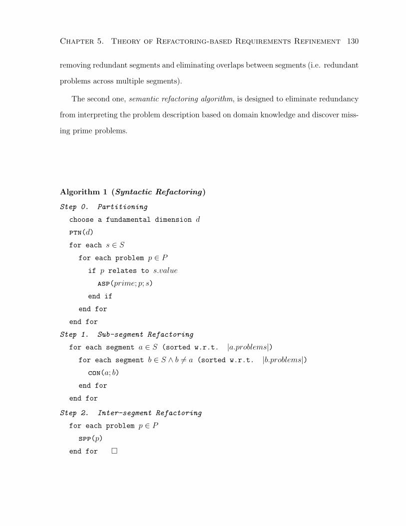
Chapter 5. Theory of Refactoring-based Requirements Refinement 130
removing redundant segments and eliminating overlaps between segments (i.e. redundant
problems across multiple segments).
The second one, semantic refactoring algorithm, is designed to eliminate redundancy
from interpreting the problem description based on domain knowledge and discover miss-
ing prime problems.
Algorithm 1 (Syntactic Refactoring)
Step 0. Partitioning
choose a fundamental dimension d
ptn(d)
for each s ∈ Sfor each problem p ∈ P
if p relates to s.value
asp(prime; p; s)
end if
end for
end for
Step 1. Sub-segment Refactoring
for each segment a ∈ S (sorted w.r.t. |a.problems|)for each segment b ∈ S ∧ b 6= a (sorted w.r.t. |b.problems|)
con(a; b)
end for
end for
Step 2. Inter-segment Refactoring
for each problem p ∈ Pspp(p)
end for �

Chapter 5. Theory of Refactoring-based Requirements Refinement 131
Analysis
Step 0 formulates the initial partition. Step 1 handles redundant segments (two segments
contain the same problems). For consistent results, sort the segments in the same ordering
(either descending or ascending) in both loops with respect the number of problems they
are associated with. Step 2 handles the overlaps between segments.
A corollary of Step 0 is that no segment is empty since the values of the dimension
(entity types) are taken from problem descriptions, thus each segment must have at least
one problem associated to. By the same token, the rank of any problem is at least 1 and
at most the total number of distinct segments, which ensures the correct operation and
termination (see below) of Step 2.
In Step 0, the number of iterations is bounded by np ·ns where np is the current total
number of problems, and ns is the size of the dimension (or number of segments). Step 1
requires at worst n2s iterations. Step 2 requires at worst np ·ns iterations. Since np ≥ ns,
the algorithm is bounded by O(np · ns).
It is critical to choose an appropriate dimension before applying this algorithm. A
poor choice of the dimension may result in a poor decomposition of the system, in the
worst case, a single component (segment). The trick in selecting an initial dimension is
in finding one that maximizes the separation of concerns among the requirements and
has the most potential to organize the system behaviors into decoupled components that
reduces design and implementation effort. To name a few, we have business-entity types,
data types, business units, service types, utility groups, controls, etc. An experienced
designer may find it easy to select an appropriate initial dimension while a novice designer
may need a few attempts of trial and error.
Algorithm 2 (Semantic Refactoring)
Step 0. Intra-segment Refactoring
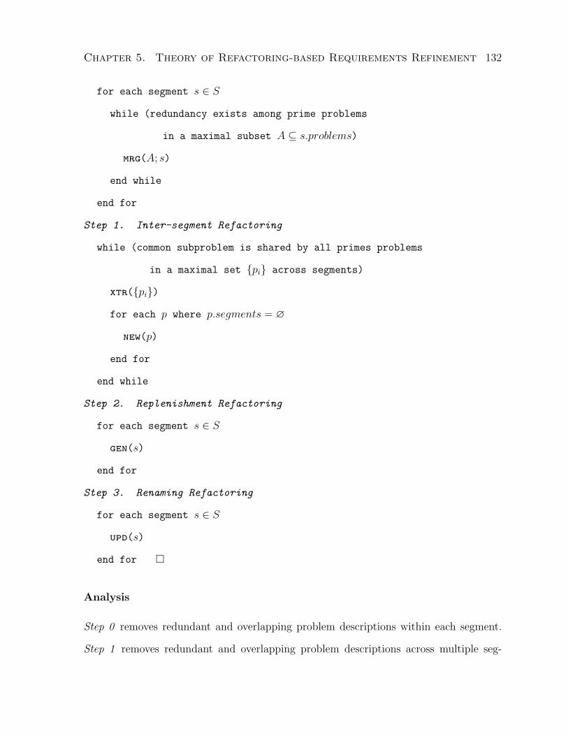
Chapter 5. Theory of Refactoring-based Requirements Refinement 132
for each segment s ∈ S
while (redundancy exists among prime problems
in a maximal subset A ⊆ s.problems)
mrg(A; s)
end while
end for
Step 1. Inter-segment Refactoring
while (common subproblem is shared by all primes problems
in a maximal set {pi} across segments)
xtr({pi})
for each p where p.segments = ∅
new(p)
end for
end while
Step 2. Replenishment Refactoring
for each segment s ∈ S
gen(s)
end for
Step 3. Renaming Refactoring
for each segment s ∈ S
upd(s)
end for �
Analysis
Step 0 removes redundant and overlapping problem descriptions within each segment.
Step 1 removes redundant and overlapping problem descriptions across multiple seg-

Chapter 5. Theory of Refactoring-based Requirements Refinement 133
ments. The common subproblem (overlap) is extracted and often is assigned to a new
segment. Its connection to the relevant segments is maintained through interface prob-
lems. The overlapping problems descriptions are updated. When a prime problem has
trivial or no description as it may happen after an extraction, it is removed. Step 2
supplements problems that support basic CRUD properties to each segment. Step 3 up-
dates the segment. When a segment contains no prime problem, as it may happen after
common subproblem is extracted and assigned elsewhere and genfails to generate any
prime problems, it is removed.
The algorithm terminates in finite steps and the postcondition is guaranteed upon
completion. The time bound for Step 0 is similar to finding equivalence classes within
each segment (redundancy is the equivalence relation), which requires O(n2sp ·ns) compar-
isons, where nsp is the highest number of prime or interface problems in any segment, and
ns is the number of segments. Step 1 is similar to finding equivalence classes among prime
problems across segments, which requires O(n2pp) comparisons, where npp is the number of
total prime problems. The updates will take O(np) steps, where np is the number of total
problems. Step 2 takes O(ns · nsp). Step 3 requires O(ns) steps. Overall, the algorithm
terminates within O(max(n2sp ·ns, n2
pp, np)) steps since nsp ≥ 1⇒ n2sp ·ns ≥ ns ·nsp ≥ ns.
At the end of the problem-level requirements refactoring, the following postconditions
should be met:
• No redundant problem descriptions within a segment
• No overlaps between segments (with respect to prime problems)
• No unassigned problems
• No further division or consolidation of segments given the existing dimensions
• No overlaps between prime problem descriptions

Chapter 5. Theory of Refactoring-based Requirements Refinement 134
• No new problem can be uncovered/defined given the existing dimensions
5.3.3.2 Domain-level Refactoring
This level of refactoring is aimed at capturing and exploring both external and internal
design concerns during the construction of a static system layout. It is applied specifi-
cally in the Solution Perspective Phase. There is no explicit refactoring in the Domain
Description Phase. It is a step in the refinement process to to identify functions that
refine the problems defined in the problem-level. The subsequent refinement phases will
apply refactoring on these functions. An example is given in Chapter 6 to illustrate how
it is applied.
One generic algorithm, Multi-Dimensional Refactoring, is defined to handle various
design concerns via customization. The customization is made by instantiated the al-
gorithm along a chosen dimension (representing the design concern) into a heuristic.
Below is the definition of the algorithm and its analysis followed by further discussions
on heuristics.
Algorithm 3 (Multi-Dimensional Refactoring)
Step 0. Division
given a dimension d ∈ D
for each segment s ∈ S
div(s; d)
end for
Step 1. Establishment
for each segment s ∈ S
if s.value ∈ d.values
est(s; s.value)

Chapter 5. Theory of Refactoring-based Requirements Refinement 135
end if
end for
Step 2. Simplification
Apply Algorithm 2 to remove redundant or overlapping descriptions among
segments until problem-level postconditions are met.
Step 3. Reiteration
Apply Steps 0-2 along each previously applied dimension to only the
newly established segment. Note each reapplication of a prior dimension
usually involves only two segments: the segment just established in
applying the current dimension, and the one established in applying the
prior dimension. �
Analysis
Step 0 applies the concerns defined in a dimension to each segment and reorganizes
the segments into parts that concern distinct values of a dimension, i.e. the parts are
decoupled according to the distinct values which represent independent concerns. Step
1 summarizes the concerns and create new prime problems to represent them for each
segment. As a result, redundancy and overlap may occur as it is highly probable that
more than one segment may be associated to the same value of a dimension. Thus,
we apply Step 2 to remove such instances. When all three steps are completed (no
further refactoring can be made in this algorithm), the refactoring postcondition is again
guaranteed. Step 3 ensures that the dependency of the new segment on segments resulted
from other concerns (dimensions) is covered. Therefore making the order of dimension
application irrelevant.
It is important that the algorithm terminates in finite steps, otherwise the completion
and postcondition cannot be guaranteed. The time bound for Step 0 is O(nspp · ns), for

Chapter 5. Theory of Refactoring-based Requirements Refinement 136
Step 1 is O(ns), and for Step 2 is O(max(n2sp · ns, n2
pp, np)), where nspp is the maximum
number of prime problem of any segment (which is ≥ 1), ns is the number of existing
segments, nsp is the highest number of prime or interface problems in any segment, npp
is the number of total prime problems, and np is the number of total problems. The time
for Step 3 is bounded by that of the prior steps as the number of segments involved is
typically limited to 2 and the number of prior dimensions is a small fixed number (4 in our
case). The overall time bound therefore is O(max(n2sp · ns, n2
pp, np)) since 1 ≤ nspp ≤ nsp.
Dimension Heuristics
The multi-dimensional refactoring algorithm is purposely defined in a generic form so that
designers can deal with context-specific non-functional requirements (NFRs) or cross-
cutting concerns while constructing a system decomposition. To do so, a designer defines
a dimension (see Section 5.3.1) with respect to the concern (or NFR) and instantiate
the algorithm to a dimension heuristic and apply to the requirements. Non-functional
requirements that do not affect the design of the system layout are not considered here.
More discussion on handling non-functional requirements is given in Section 5.3.4.2.
To illustrate the instantiation, five dimensions are defined capturing common design
concerns such as security, maintenance, and extension. The dimensions are Protection,
Data Maintenance, Code Extension, Access, and Data Management. Five heuristics are
defined by instantiating the algorithm along these dimensions. Each heuristic is then
applied to the problem decomposition (refactored requirements from the problem level)
as part of the domain-level refactoring method.
Heuristics 1 through 4 deal with macro level3 issues concerning the external properties
expected of the system as a whole situated in its operating environment. Heuristic 5 deals
3As opposed to the micro point of view taken in the domain description phase.
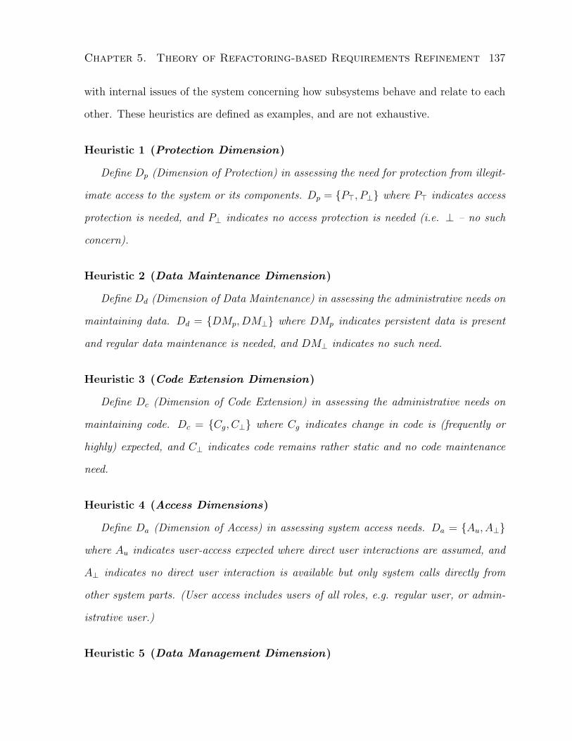
Chapter 5. Theory of Refactoring-based Requirements Refinement 137
with internal issues of the system concerning how subsystems behave and relate to each
other. These heuristics are defined as examples, and are not exhaustive.
Heuristic 1 (Protection Dimension)
Define Dp (Dimension of Protection) in assessing the need for protection from illegit-
imate access to the system or its components. Dp = {P>, P⊥} where P> indicates access
protection is needed, and P⊥ indicates no access protection is needed (i.e. ⊥ – no such
concern).
Heuristic 2 (Data Maintenance Dimension)
Define Dd (Dimension of Data Maintenance) in assessing the administrative needs on
maintaining data. Dd = {DMp, DM⊥} where DMp indicates persistent data is present
and regular data maintenance is needed, and DM⊥ indicates no such need.
Heuristic 3 (Code Extension Dimension)
Define Dc (Dimension of Code Extension) in assessing the administrative needs on
maintaining code. Dc = {Cg, C⊥} where Cg indicates change in code is (frequently or
highly) expected, and C⊥ indicates code remains rather static and no code maintenance
need.
Heuristic 4 (Access Dimensions)
Define Da (Dimension of Access) in assessing system access needs. Da = {Au, A⊥}
where Au indicates user-access expected where direct user interactions are assumed, and
A⊥ indicates no direct user interaction is available but only system calls directly from
other system parts. (User access includes users of all roles, e.g. regular user, or admin-
istrative user.)
Heuristic 5 (Data Management Dimension)

Chapter 5. Theory of Refactoring-based Requirements Refinement 138
Define Dm (Dimension of Data Management) in assessing needs for common data
management needs (such as data storage and retrieval, transaction control, version con-
trol, and parallel access) from the internal system perspective. Dm = {DG>, DG⊥} where
DG> indicates needs for any of the aforementioned data management tasks, and DG⊥
indicates no need is identified.
5.3.3.3 Product-level Refactoring
Functional requirements are deduced from problems in the two refinement phases of this
level, Product Function and User Function phases. Refactoring at this level is applied to
assign functions to segments (implemented as components) as responsibilities. Assigning
product functions to segments is straight-forward since they are extracted directly from
the problems which are associated to segments. However, assigning user functions is
trickier because they are extracted from the domain description scenarios which have no
direct mapping to segments. Algorithm 4 describes how the assignments are made.
Algorithm 4 (Function Assignment)
Precondition: All prime problems have rank 1 and interface problems
have rank > 1.
Step 0. Product Function Assignment
for each product function fp
asf(fp; fp.problems[0].segment)
end for
Step 1. User Function Assignment
Su := ∅
for each user function fu
C := fu.scenarios

Chapter 5. Theory of Refactoring-based Requirements Refinement 139
PC := ∪{c.problems | c ∈ C}
for each p ∈ PC
rlz(fu; p)
if p ∈ fu.problems
Su := Su ∪ p.segment (if p.type = interface, use p.sourceSegment)
end if
end for
if |Su| = 1
asf(f ;Su[0])
else if |Su| > 1
spf(f ;Su)
end if
end for
Postcondition: All functions are assigned to exactly 1 segment. �
Analysis
A product function is directly deduced from a prime problem, thus it is only associated
to one prime problem. Since the precondition of the algorithm limits each prime problem
to one segment, it is straight-forward to assign production functions in Step 0. This step
takes up to npf iterations, i.e., the number of product functions.
In Step 1, C denotes the set of domain scenarios that fu is extracted from, PC denotes
the set of all problems associated to any scenario in C, and Su denotes the set of segments
that contain the problems that fu realizes. When |Su| = 1, simply assign the function
to the only segment; when |Su| > 1, split the function among all involved segments
and assign the resulted functions to the corresponding segments. This step takes up to
nuf · (np + ns) iterations, where nuf is the number of user functions, np is the number of

Chapter 5. Theory of Refactoring-based Requirements Refinement 140
total problems, ns is the number segments.
The total number of iterations of this algorithm is bounded by max(npf , nuf · np) as
np > ns.
If the postcondition cannot be met, review the deduction process of the unassigned
functions and the functional descriptions to determine their appropriate assignment.
5.3.3.4 Component-level Refactoring
At this level, the refactoring method is aimed at identifying function dependencies and
generalizations.
Algorithm 5 identifies dependencies between functions of different segments. Depen-
dency may be precondition, generalization, extension, or inclusion [BRJ00]. Once the
dependencies are determined, algorithm 6 is applied to simplify the functional descrip-
tions via generalization.
Algorithm 5 (Dependency Analysis)
for each segment s
c := {s}
for each interface problem p ∈ s
c := c ∪ p.destSegment
end for
for each function f ∈ s
for each segment x ∈ c
for each function g ∈ x.functions
dep(f ; g)
end for
end for
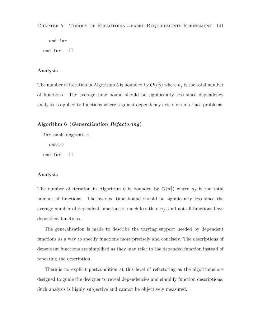
Chapter 5. Theory of Refactoring-based Requirements Refinement 141
end for
end for �
Analysis
The number of iteration in Algorithm 5 is bounded byO(n2f ) where nf is the total number
of functions. The average time bound should be significantly less since dependency
analysis is applied to functions where segment dependency exists via interface problems.
Algorithm 6 (Generalization Refactoring)
for each segment s
gnr(s)
end for �
Analysis
The number of iteration in Algorithm 6 is bounded by O(n2f ) where nf is the total
number of functions. The average time bound should be significantly less since the
average number of dependent functions is much less than nf , and not all functions have
dependent functions.
The generalization is made to describe the varying support needed by dependent
functions as a way to specify functions more precisely and concisely. The descriptions of
dependent functions are simplified as they may refer to the depended function instead of
repeating the description.
There is no explicit postcondition at this level of refactoring as the algorithms are
designed to guide the designer to reveal dependencies and simplify function descriptions.
Such analysis is highly subjective and cannot be objectively measured.

Chapter 5. Theory of Refactoring-based Requirements Refinement 142
5.3.4 Discussions
Two issues concerning the usability of the theory are discussed in this section. The
first is the intent preservation in requirements refactoring and the impact of human
factors (designer analysis) in the method. The second is how the framework handles
non-functional requirements.
5.3.4.1 Intent Preservation and Human Factors
In the building architecture domain, different designers often come up with different
building designs given the same set of requirements. Similarly, it is no surprise that
different software designers may come up with different software designs in meeting a
given set of requirements. The difference is often due to the human factors involved in
the design process. Consequently, an effective software design tool (or method) that is
applied to multiple levels of abstraction cannot ignore human factors and solve software
design problems only in a formalized automated fashion. Furthermore, if a designer is
forced to follow a method exactly without any room to incorporate additional thought and
analysis for the specific design problem, the designer will simply abandon the method. To
provide any degree of usefulness and general applicability, a design method must provide a
degree of flexibility in accommodating and incorporating human factors, therefore cannot
be completely formal or fully automated.
The R3 theory is designed under such a philosophy. The refinement model sets
up a general framework for (software) designers to carry out appropriate analysis with
respect to requirements at different abstraction levels. The refactoring method, defined in
this framework, is intended to help designers to structure the requirements and perform
analysis towards design. The method provides a platform for designers to manipulate
requirements in order to gain a better understanding. The platform guides the designer’s

Chapter 5. Theory of Refactoring-based Requirements Refinement 143
attention to places where specific analysis is needed in completing and simplifying the
requirements towards producing an initial draft design. This allows the designer to act on
what is present in the problem (intrinsic structure and properties of the requirements),
as opposed to trying to fit the requirements into an existing form of solution (pattern
or style). The specific analysis performed is not part of the refactoring method. Strictly
speaking, the analysis is a refinement action, which indicates this method does not have a
“pure” form of requirements refactoring4. Consequently, the analytical style and ability
of the designer will largely influence the outcome of the method.
Refactoring, defined in the literature for programming and design, has the property
of behavior preservation. To apply refactoring in the requirements context, it is natural
to expect a similar property. Unlike design and code, requirements are, in general, not
limited to behavior descriptions. Behavior preservation is thus insufficient here. The
equivalent concept in the requirements context would be to preserve the meaning of
requirements, or the intent. Below, we discuss the intent-preserving property of individual
refactoring operators. Since designer’s analysis is not part of our refactoring method, we
discuss intent preservation excluding the effect of analysis. However, we do comment on
how the effect of analysis influences the outcome of the method, when applied by different
designers.
The refactoring operators, asp, new, upd, div, rlz, and asf, concern with mechan-
ical structuring of requirements into segments (components), and operator dep identifies
relationships between functions. All of these operators make no alteration to any require-
ment description, thus, the intent is trivially preserved. The analysis is simply to deter-
mine associations among requirements. The differences in the outcome of the method,
when applied by different designers, are limited to the structure of decomposition and
4It has been shown in Section 4.2.2 that a “pure” form of requirements refactoring is undesirable bydesigners.

Chapter 5. Theory of Refactoring-based Requirements Refinement 144
not to the content of components’ responsibilities (requirement descriptions).
The operators below involve more intensive analysis by the designer, and the outcome
of the method may include varied requirement descriptions from designer to designer
depending on their analytical style and ability. Design reviews and stakeholder reviews
are recommended for the outcome of these operators.
• ptn : The intent is trivially preserved as no alteration is made to any requirement
descriptions. The choice of the dimension affects the outcome.
• con : The intent is trivially preserved as no alteration is made to any requirement
descriptions. The decision that two segments are independent enough to remain as
separate segments affects the outcome.
• spp : Alterations are made to requirement descriptions as subproblems are defined
in place of the original problem. The alterations are results of the analysis (re-
finement action). The refactoring action defined in the operator only deals with
associating the subproblems to segments, which makes no alteration to any require-
ment descriptions. By our definition, it preserves the intent.
The analysis, including defining the subproblems based on the original problem
relevant to the corresponding segments and ensuring they are distinct, total, and
sound with respect to the original problem, affects the outcome.
• xtr : Alterations are made to requirement descriptions as a common subproblem is
extracted the original problems, new interface problems are defined to indicate de-
pendencies, and updates are made to the original problems to exclude the common
subproblem. The alterations are results of the analysis (refinement action). The
refactoring action defined in the operator only deals with associating the problems
to segments, which makes no alteration to any requirement descriptions. By our

Chapter 5. Theory of Refactoring-based Requirements Refinement 145
definition, it preserves the intent.
The analysis, including discovering problem overlaps, extracting the common sub-
problem among the overlapping problems, defining new interface problems, and
update original problem descriptions, affects the outcome.
• gen : Alterations are made to requirement descriptions as missing problems are
defined. The alterations are results of the analysis (refinement action). The refac-
toring action defined in the operator only deals with associating the problems to
segments, which makes no alteration to any requirement descriptions. By our def-
inition, it preserves the intent.
The analysis of identifying and defining missing problems in a segment affects the
outcome.
• est : The intent is trivially preserved as no alteration is made to any requirement
descriptions.
The analysis of precisely defining the problem representing the dimension value in
the relevant segment affects the outcome.
• spf : Alterations are made to requirement descriptions as subfunctions are defined
in place of the original function. The alterations are results of the analysis (re-
finement action). The refactoring action defined in the operator only deals with
associating the subfunctions to segments, which makes no alteration to any require-
ment descriptions. By our definition, it preserves the intent.
The analysis, including ensuring the subfunctions are distinct, total, and sound with
respect to the original function and correspond to the relevant segment, affects the
outcome.
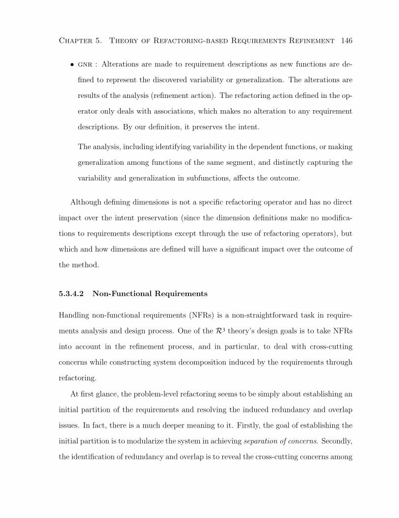
Chapter 5. Theory of Refactoring-based Requirements Refinement 146
• gnr : Alterations are made to requirement descriptions as new functions are de-
fined to represent the discovered variability or generalization. The alterations are
results of the analysis (refinement action). The refactoring action defined in the op-
erator only deals with associations, which makes no alteration to any requirement
descriptions. By our definition, it preserves the intent.
The analysis, including identifying variability in the dependent functions, or making
generalization among functions of the same segment, and distinctly capturing the
variability and generalization in subfunctions, affects the outcome.
Although defining dimensions is not a specific refactoring operator and has no direct
impact over the intent preservation (since the dimension definitions make no modifica-
tions to requirements descriptions except through the use of refactoring operators), but
which and how dimensions are defined will have a significant impact over the outcome of
the method.
5.3.4.2 Non-Functional Requirements
Handling non-functional requirements (NFRs) is a non-straightforward task in require-
ments analysis and design process. One of the R3 theory’s design goals is to take NFRs
into account in the refinement process, and in particular, to deal with cross-cutting
concerns while constructing system decomposition induced by the requirements through
refactoring.
At first glance, the problem-level refactoring seems to be simply about establishing an
initial partition of the requirements and resolving the induced redundancy and overlap
issues. In fact, there is a much deeper meaning to it. Firstly, the goal of establishing the
initial partition is to modularize the system in achieving separation of concerns. Secondly,
the identification of redundancy and overlap is to reveal the cross-cutting concerns among

Chapter 5. Theory of Refactoring-based Requirements Refinement 147
the requirements in the established modularization. Thirdly, the resolution of syntactic
redundancy is to ensure the separation of concerns is well established. Fourthly, the
resolution of semantic redundancy is to ensure cross-cutting concerns are well handled.
The domain-level refactoring is designed to handle cross-cutting NFRs that are spe-
cific to the problem in hand. The designer has the flexibility to specify the NFR through
a dimension, instantiate the multi-dimensional refactoring algorithm in a heuristic, and
decompose the system with respect to the NFR. Examples of such NFRs are secu-
rity, extensibility, access, maintainability, fault-tolerance (fail-over), and common data-
management.
The product and component-level refactoring supports simplicity as they reveal com-
plex relationships between functions and generalize common functions to simplify de-
scriptions.
The R3 theory is designed to assist designer to better understand and structure
requirements towards design, specifically, a system layout design. The theory is not
meant to replace or automate the design activity. The candidate design resulted from
refactoring is essentially a structural representation of the requirements which should
be used as a reference in selecting an appropriate architectural style while analyzing
potential NFR trade-offs.
Non-cross-cutting NFRs are treated the same way as typical (functional) require-
ments, specified either in problems or functions. The distinctions are not made unless
they affect the system layout. Such NFRs are responsibilities of specific components no
different from other requirements. For example, specific measurable performance require-
ments for certain user interactions with the system are treated as typical requirements
which are assigned to specific components along with the problems specifying the in-
teractions and will be realized in the low-level design, implementation, or deployment
stage.

Chapter 5. Theory of Refactoring-based Requirements Refinement 148
There are also some NFRs that have an overall effect over the system, e.g., availability
and robustness, but are independent of the system layout. They are mostly resolved at
implementation (programming) and deployment stages.
In summary, the R3 theory allows designers to consider the effect of cross-cutting
NFRs over the system layout design, but is not meant to analyze and handle all NFRs.
5.4 Summary
This chapter presented a refactoring-based requirements refinement design theory. The
theory’s constructs, refinement model (or framework), and refactoring method are de-
fined. A discussion is given on issues of human factors over the method, intent preser-
vation of requirements refactoring, and handling non-functional requirements. The next
chapter presents the details of the application of the theory to an industry case study.

Chapter 6
Case Study
In this chapter, I present the application of the R3 refinement framework and refactoring
method to an industry case study, Employee Workplace (EW), and a comparison to an
industry solution produced using Rational Unified Process (RUP) [Kru00].
The case study describes a desirable electronic process control, communication, and
information sharing application for employees. There is a large body of accessible docu-
mentation [Lym05] and an industry solution is available from our prior empirical study
[LLE05]. The case study is sufficiently complex that demonstrates the applicability of
the R3 framework and method to large real-world problems.
6.1 Applying Refinement and Refactoring
The application of refinement and refactoring is presented according to the refinement
phases defined in Chapter 5.
149

Chapter 6. Case Study 150
6.1.1 Problem-level Refactoring
In the Business Vision Phase, problem descriptions of EW are defined. They are adopted
from the existing documentation [Lym05]. Table 6.1 summarizes the problems (business
needs) of EW and Table 6.2 provides an example of an elaborated problem. The full
list of elaborated problems is included in Appendix B. These descriptions are not well
organized and contain a high degree of redundancy.
We start with the syntactic refactoring or symbolic refactoring to ensure unique as-
signments of problems to segments are made, and then move on to semantic refactoring
to eliminate description overlap and redundancy between problems.
Example 6.1 (EW Syntactic Refactoring)
Using business-entity-type (data type) as the initial dimension and we can identify
7 business-entity types from the business needs: text message, real-time video, business
content, document, employee info, policy and procedure, and record.
Step 0, apply ptn to the business-entity-type dimension and form a partition of 7
segments. Apply asp so that each problem is assigned to a segment. We obtain an initial
problem partition, shown in Table 6.3 (spanning problems are marked in bold). Step 0
is applied under these assumptions: i) information in P4 refers to business content,
document, and employee info; ii) business information and company information in P2
and P9 refer to business content; and iii) retention rules in P12 is a kind of policy.
Next, apply Step 1. Over all the segments, the top two (text message and real-time
video) are consolidated into one, and after applying est, we get segment communication
which has P1 as a prime problem.
Last, apply Step 2. The spanning problems are identified to be: P4, P9, P11, P12,
P13 sorted according to their rank. Start from P4 (Find information and historical
background easily), apply spp to P4 and the spanning segments business content,

Chapter 6. Case Study 151
Table 6.1: Summary of initial business needs
ID Business Need Summary
P1 Enhance casual and formal communication across geographical sites
P2 Make up-to-date business information readily available to all employees
P3 Define business processes that can be automatically executed with routing, track-
ing, and notification services
P4 Find information and historical background easily
P5 Protect document authenticity and integrity while sharing
P6 Author and manage large documents from parts
P7 Reuse documented information without duplicating the content
P8 Store and retrieve documentations more cost-effectively
P9 Provide search capability on company and employee information
P10 Capture business processes with enforced execution and provide progress track-
ing and notifications (process management)
P11 Provide traceable and enforceable control over document creation, modification
and access
P12 Manage records according to retention rules
P13 Enforce approval process in releasing corporate information
Table 6.2: Business need, P1
P1 Enhance casual and formal communication across geographical sites
Problem
– Inefficient methods of communication
Impact
– Collaboration is not as effective as needed
– Costly travel may be required
Desirable Solutions
– Facilitate communication across multiple geographical sites
– Improve effectiveness of collaboration towards productivity increase
– Reduce need for face-to-face communication and save travel costs

Chapter 6. Case Study 152
document, and employee info, and obtain P4a (Provide search on business content),
P4b (Provide search on documents), P4c (Provide search on employee info) assigned
to the three segments respectively. Similarly, apply spp to the other spanning prob-
lems (P9, P11, P12, P13) and obtain P9b, P9c, P11a′, P12a′, and P13a′. The resulting
partition is shown in Table 6.4 and descriptions in Table 6.5.
Example 6.2 (EW Semantic Refactoring)
Apply Step 0 (Intra-segment refactoring) to the problem partition shown in Table 6.4,
we identify redundancy in description between P4a (Provide search on business content)
and P9b (Provide search on business content) on searching business content. Apply mrg
to P4a and P9b, and obtain the newly merged problem which (for simplicity reasons)
is still called P4a (Provide search on business content) since no change is made. P9b is
removed.
Similarly, redundancy is found between P4c (Provide search on employee info) and
P9c (Provide search on employee info). Apply mrg to them, we get P4c referring to the
newly merged problem (P9c is removed).
Next, overlapping description is found between P3 (Define business processes that
can be automatically executed with routing, tracking, and notification services), P10
(Capture business processes with enforced execution and provide progress tracking and
notifications), P11a′ (Enforce access control through predefined and automated pro-
cesses), P12a′ (Enforce retention rules), P13a′ (Enforce approval through predefined
and automated processes). They are merged into P10′ (Define business processes with
automatically enforced execution and provide progress tracking and notifications; pro-
cesses include that of document control, retention, and approval). The resulting problem
partition is given in Table 6.6.

Chapter 6. Case Study 153
Table 6.3: Initial problem partition (spanning problems are in bold)
Business Entity Problems
Text message P1
Real-time video P1
Business content P2,P4,P9,P13
Document P4, P5, P6, P7, P8,P11
Employee info P4,P9
Policy and procedure P3, P10,P11,P12,P13
Record P12
Table 6.4: Results of syntactic refactoring
Segment Prime
Communication P1
Business content P2, P4a, P9b, P13
Document P4b, P5, P6, P7, P8, P11
Employee info P4c, P9c
Policy and procedure P3, P10, P11a′, P12a′, P13a′
Record P12

Chapter 6. Case Study 154
Apply Step 1 (Inter-segment refactoring), a common subproblem on search is iden-
tified among P4a (Provide search on business content), P4b (Provide search on doc-
uments), and P4c (Provide search on employee info) across three segments: business
content, document, and employee info. Apply xtr, we obtain a new problem, P4d
(Search on criteria), problems P4a, P4b, and P4c are now marked as interface problems
in the corresponding segments. Since P4d cannot be uniquely and rationally assigned to
any existing segments, we apply new to obtain a new segment, search, to which P4d is
assigned as a prime problem, and P4a, P4b, P4c are assigned as interface problems.
Another common subproblem is found between P10′ (see above), P11 (Provide trace-
able and enforceable control over document creation, modification and access), P12 (Man-
age records according to retention rules), and P13 (Enforce approval process in releasing
corporate information) concerning process control over document, record retention, and
approval respectively. Apply xtr to them and obtain the extracted problem defined as
P10a (Define business processes with automatically enforced execution), and interface
problems P11b, P12b, and P13b, and prime problems P10b (Allow progress tracking and
notifications of auto-executed business processes), P11a (Provide audit trail and access
control over documents), P12a (Manage retention records), and P13a (Maintain and
manage company information), each remain in the original containing segments. Apply
asp to assign P10a as prime problem to segment policy and procedure. The resulting
problem partition is given in Table 6.7.
Apply Step 2, only segment employee info lacks CRUD support for its data. Apply
gen, we generate a new prime problem, P9a (Maintain employee info), in this segment.
Apply Step 3, all segments (except the first one) are given new names to describe its
prime functions.
The problem decomposition is presented in Tables 6.8 and 6.9, and Figure 6.1

Chapter 6. Case Study 155
Table 6.5: Problem descriptions after syntactic refactoring
ID Business Need Summary
P1− P3, P5− P8, P10, P11, P12, P13 remain the same as in Table 6.1
P4a Provide search on business content
P4b Provide search on documents
P4c Provide search on employee info
P9b Provide search on business content
P9c Provide search on employee info
P11a′ Enforce access control through predefined and automated processes
P12a′ Enforce retention rules
P13a′ Enforce approval through predefined and automated processes
Table 6.6: Results of intra-segment refactoring
Segment Prime
Communication P1
Business content P2, P4a, P13
Document P4b, P5, P6, P7, P8, P11
Employee info P4c
Policy and procedure P10′
Record P12

Chapter 6. Case Study 156
Table 6.7: Results of inter-segment refactoring
Segment Prime Interface
Communication P1
Business content P2, P13a P4a, P13b
Document P5, P6, P7, P8, P11a P4b, P11b
Employee info P4c
Policy and procedure P10a, P10b P11b, P12b, P13b
Record P12a P12b
Search P4d P4a, P4b, P4c
Table 6.8: The problem decomposition
Segment Prime Interface
Communication P1
Content Management P2, P13a P4a, P13b
Document Management P5, P6, P7, P8, P11a P4b, P11b
Employee Directory P9a P4c
Process Management P10a, P10b P11b, P12b, P13b
Retention Management P12a P12b
Search Engine P4d P4a, P4b, P4c

Chapter 6. Case Study 157
Table 6.9: Problem-level refined business needs
ID Business Need Summary
P1 Enhance casual and formal communication across geographical sites
P2 Make up-to-date business information readily available to all employees
P3 Define business processes that can be automatically executed with routing, track-
ing, and notification services
P4a Provide search on business content
P4b Provide search on documents
P4c Provide search on employee info
P4d Search on criteria
P5 Protect document authenticity and integrity while sharing
P6 Author and manage large documents from parts
P7 Reuse documented information without duplicating the content
P8 Store and retrieve documentations more cost-effectively
P9a Maintain employee info
P10a Define business processes with automatically enforced execution
P10b Allow progress tracking and notifications of auto-executed business processes
P11a Provide audit trail and access control over documents
P11b Enforce access control through predefined and automated processes
P12a Manage retention records
P12b Enforce retention rules
P13a Maintain and manage company information
P13b Enforce approval through predefined and automated processes

Chapter 6. Case Study 158
6.1.2 Domain-level Refactoring
In the Solution Perspective Phase, the domain-level refactoring is applied. I illustrate the
application of Algorithm 3 for each heuristic defined in 5. Recall Protection Dimension
Dp = {P>, P⊥} where P> indicates access protection is needed, and P⊥ indicates no
access protection is needed (i.e. ⊥ – no such concern).
Example 6.3 (EW Protection Dimension Refactoring)
Given the problem decomposition in Table 6.8 and descriptions in Table 6.9, we apply
Step 0 along the Protection Dimension and obtain the same set of segments as before
since no prime problem in any segment is associated to P⊥, therefore, no division is made.
In Step 1, we establish a new prime problem in each segment: P14i (Authenticate and
authorize user for segment i). We know these prime problems have an overlapping con-
cern regarding authentication and authorization, thus we proceed to Step 2 by applying
Algorithm 2 to remove the overlap.
In Step 2, apply Algorithm 2, we skip its Step 0 as it does not apply. After Step 1, we
obtain new prime problem P14a (Provide means for authentication and authorization)
and interface problem1 P14b (Able to verify authorization level) in place of P14i, and
a new segment, authentication and authorization. Assign P14a to the new segment
and P14b to all mentioned segments (including the new one). After the extraction of
P14a, P14b, all P14i become trivial and are removed. Steps 2 and 3 of Algorithm 2 cause
no effect.
Step 3 is currently non-applicable as this is the first dimension applied. Figure 6.2
shows the new dependencies between the segments.
1As the description of the interface problem for each segment is roughly the same, for simplicityreasons, I use one interface problem, P14b, to represent all. This is reasonable as the description canalways be parameterized.

Chapter 6. Case Study 159
(P5-P8, P11a) (P1)(P2, P13a)
(P12a)
(P4d) (P9a)P4c
P12b(P10a,P10b)
Figure 6.1: Problem decomposition and dependencies
P14b
P14b P14b
Content Management
Search EngineEmployee Directory
Process Management
Retention Management
Document Management
CommunicationP14b
P14b
P14b
Authorization & Authentication
(P14a)
P14b
Figure 6.2: Dependencies on Authentication and Authorization

Chapter 6. Case Study 160
Recall Data Maintenance Dimension Dd = {DMp, DM⊥} where DMp indicates per-
sistent data is present and regular data maintenance is needed, and DM⊥ indicates no
such need.
Example 6.4 (EW Data Maintenance Dimension Refactoring)
Following the partition updated by Figure 6.2, we apply Step 0 along the Data Main-
tenance Dimension. All prime problems are associated to DMp except that of the search
segment. We maintain the same set of segments as before since no division is made.
In Step 1, establish a new prime problem in each segment (except search): P18i
(Regular data maintenance routines such as scheduled data backup and recovery are
needed to protect data from unexpected loss for segment i).
In Step 2, apply Algorithm 2 to remove the overlap among P18i where we obtain
segment data maintenance which is assigned a prime problem, P18 (Regular data main-
tenance routines such as scheduled data backup and recovery are needed to protect data
from unexpected loss), and an interface problem P18′ (Access to data maintenance rou-
tine). P18′ is assigned to all segments except search as interface problem. The extraction
eliminates all P18i.
In Step 3, we first obtain P14DM (Authenticate and authorize user for segment data
maintenance) as a prime problem to segment data maintenance; then we identify the
overlap between P14DM and P14a (Provide means for authentication and authorization),
the extraction returns P14a untouched and eliminates P14DM while adding P14b (Able
to verify authorization level) as an interface problem to segment data maintenance. The
new dependencies between segments are shown in Figure 6.3.
Recall Code Extension Dimension Dc = {Cg, C⊥} where Cg indicates change in code
is (frequently or highly) expected, and C⊥ indicates code remains rather static and no
code maintenance need.

Chapter 6. Case Study 161
P18'
P18' P18'
P18'
P18'
P18
'P18'
(P18)
P14
bFigure 6.3: Segment Data Maintenance and its dependencies
Example 6.5 (EW Code Extension Dimension Refactoring)
Apply Step 0 along the Code Extension Dimension. Prime problems of segments
communication, content management, document management are associated to Cg. No
division is made.
In Step 1, establish a new prime problem in each segment: P17i (Provide basic
functions for easy code extension for segment i).
In Step 2, apply Algorithm 2 to remove the overlap among P17i where we obtain
segment plug-in which is assigned a prime problem, P17a (Provide basic functions such
that new features can be easily added – plug-and-play), and an interface problem P17b
(Act as a proxy to allow new functions via plug-in). P17b is also assigned to the three
relevant segments as interface problem. The extraction eliminates all P17i.
In Step 3, we start from the Protection Dimension where we obtain P14PI (Authenti-
cate and authorize user for segment plug-in) as a prime problem to segment plug-in. We
identify the overlap between P14PI and P14a (Provide means for authentication and au-
thorization). The extraction returns P14a untouched and eliminates P14PI while adding

Chapter 6. Case Study 162
Plug-in(P17a)
Data Maintenance
Authorization & Authentication
P17b
P17b
Content Management
Document Management
Communication
P17b
P18'
P14b
Figure 6.4: The Plug-in Segment and its dependencies
P14b (Able to verify authorization level) as an interface problem to segment plug-in.
Next, we apply the Data Maintenance Dimension. We obtain P18PI (Regular data
maintenance routines such as scheduled data backup and recovery are needed to protect
data from unexpected loss for segment plug-in), a prime problem to segment plug-in.
Similarly, the overlap between P18PI and P18 (Regular data maintenance routines such
as scheduled data backup and recovery are needed to protect data from unexpected loss)
results in P18 remaining the prime problem for segment data maintenance, P18′ (Access
to data maintenance routine) is assigned to segment plug-in as interface problem, and
P18PI is removed. The new dependencies between relevant segments are shown in Figure
6.4.
Recall Access Dimension Da = {Au, A⊥} where Au indicates user-access expected
where direct user interactions are assumed, and A⊥ indicates no direct user interaction
is available but only system calls directly from other system parts. (User access includes
users of all roles, e.g. regular user, or administrative user.)
Example 6.6 (EW Access Dimension Refactoring)
Apply Step 0 along the Access Dimension. Prime problems of all segments except
process management are associated to Au. In the segment process management, P10a

Chapter 6. Case Study 163
(Define business processes with automatically enforced execution) is associated to A⊥
and P10b (Allow progress tracking and notifications of auto-executed business processes)
is associated to Au, thus process management is divided into two segments: task manager
(user-access) and life cycle management (system-call). All of interface problems from
process management are assigned to life cycle management, but P14b (Able to verify
authorization level) and P18′ (Access to data maintenance routine) are assigned to task
manager. A new interface problem, 10c (Provide progress tracking and notifications of
auto-executed business processes), is also created because of the connection between
P10a and 10b, and it is assigned to both segments.
In Step 1, we establish a new prime problem in each segment: P15i (Provide user
access to available functions for segment i).
In Step 2, apply Algorithm 2 to remove the overlap among P15i where we obtain
segment navigation and view which is assigned a prime problem, P15a (Provide means
to browse and choose from available user tasks), and an interface problem P15b (Able to
invoke the system functions from any chosen user tasks). P15b is also assigned to all the
segments as interface problem. The extraction eliminates all P15i.
In Step 3, we start from the Protection Dimension where we obtain P14NV (Au-
thenticate and authorize user for segment navigation and view) as a prime problem to
segment navigation and view; then we identify the overlap between P14NV and P14a
(Provide means for authentication and authorization), the extraction returns P14a un-
touched and eliminates P14NV while adding P14b (Able to verify authorization level)
as an interface problem to segment navigation and view. However, nothing changes for
the next two dimensions, Data Maintenance and Code Extension, as only DM⊥ and C⊥
are associated. The new dependencies between segments are shown in Figure 6.6.
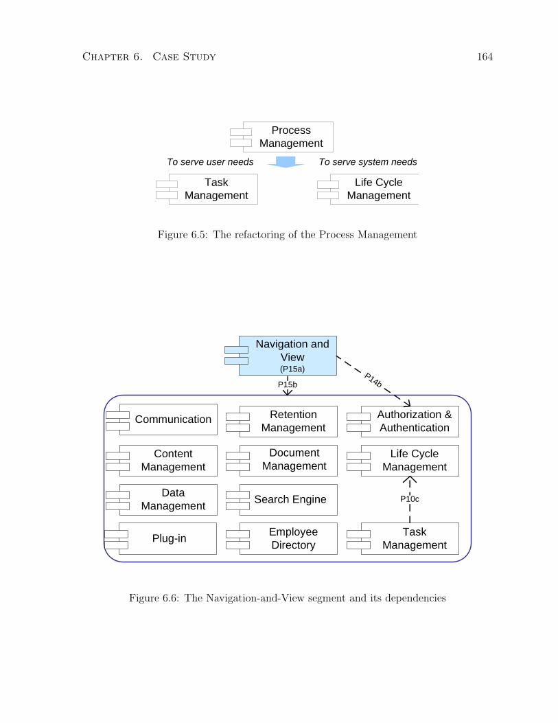
Chapter 6. Case Study 164
Life Cycle Management
Task Management
Process Management
To serve user needs To serve system needs
Figure 6.5: The refactoring of the Process Management
Document Management
Communication
Content Management
Authorization & Authentication
Retention Management
Data Management
Employee Directory
Life Cycle Management
Plug-in
Search Engine P10c
Navigation and View(P15a)
Task Management
P15bP14b
Figure 6.6: The Navigation-and-View segment and its dependencies

Chapter 6. Case Study 165
Recall Data Management Dimension Dm = {DG>, DG⊥} where DG> indicates needs
for any of the aforementioned data management tasks, and DG⊥ indicates no need is
identified.
Example 6.7 (EW Data Management Dimension Refactoring)
Apply Step 0 along the Data Management Dimension. Prime problems of all segments
except navigation and view are associated to DG>. No division is made.
In Step 1, we establish a new prime problem in each segment: P19i (Manage data
storage and retrieval, transaction, version control, and parallel access for segment i).
In Step 2, apply Algorithm 2 to the removal of overlaps between P19i and P18 (Regu-
lar data maintenance routines such as scheduled data backup and recovery are needed to
protect data from unexpected loss) results in two prime problems, P18a (Provide means
to manage data persistence) and P18b (Provide means to manage data transaction, ver-
sion control, and parallel access), which are both assigned to segment data management,
and an interface problem, P18c (Delegate data management tasks), assigned to all seg-
ments except navigation and view. The extraction eliminates all P19i. The segment
update step changes the segment name data management to data repository.
In Step 3, no change is made as the segment data repository exists before as data
management, and no new dependency is found. The updated dependencies between seg-
ments are shown in Figure 6.7.
Note the DG> value in this dimension can be extended into 4 new component-level
dimensions: data persistence, transaction control, version control, and parallel access.
They can be used to identify sub-components within data repository. The details are
left as an exercise for the readers.
The final solution decomposition for EW is presented in Figure 6.8, specified in Table
6.10 with the refined problem descriptions given in Table 6.11. A dependency link from

Chapter 6. Case Study 166
Document Management
Communication
Content Management
Authorization & Authentication
Retention Management
Employee Directory
Life Cycle Management
Plug-in Search Engine
Data Repository(P18a,P18b)
P18c
Task Management
P14b
Figure 6.7: Dependencies on Data Repository
P14b
P13b
P15b
Authorization & Authentication
(P14a)
Navigation and View
(P15a)
P4aP4b
Search Engine(P4a)
Communication(P1)
Employee Dir(P9a)
P18c
P14
b
P14b
P11b
Retention Mgmt(P12a)
Document Mgmt(P5-8, P11a)
P12bP4c
P18c
Plug-in(P17a)
Data Repository(P18a,P18b)
Life Cycle Mgmt(P10a)
Task Mgmt(P10b)
P10c
P17b
P17b
P17b
Content Mgmt(P2, P13a)
Figure 6.8: Solution decomposition and dependencies

Chapter 6. Case Study 167
A to B represents a call from A to B for a service (function). Dependency links on a
container apply to all its members.
Domain Description Phase
In the EW case study, the domain description is represented in text-based scenarios
extended with work flows. Each scenario, written as a storyline, describes an end-to-end
task involve one or more users that can be inferred from the problem decomposition.
Business flows of specific interactions between users and business entities in scenarios are
defined in work flows using BPMN (Business Process Management Notation) [Whi04].
Seven scenarios (with one work flow) have been developed which are listed in Table
6.12. These scenarios are used to identify 34 use cases summarized in Table 6.13.
A sample scenario of this case study is shown below and an example of work flow is
shown in Figure 6.9.
Scenario: Meeting via Web Conference
The promotion manager schedules a Web conference with her marketing reps about
the Fall Campaign. In this meeting, they plan to come up with the activities and
promotions for the campaign. The meeting is composed of a presentation given
by the promotion manager on the overall brand strategy and a team discussion on
budget and ideas of the campaign.
Since many of the reps work outside of the office frequently, the promotion manager
decides to schedule a Web conference instead. In the Web conference notice, she
reminds the team to prepare for the meeting by reviewing the current plan and
market research materials in the shared work area.
During the conference, the promotion manager delivers the presentation, then opens
the budget spreadsheet in the shared work area available through the Web confer-
ence, and starts a discussion with the team. The budget is very constrained and
the team is not pleased. She encourages the team to brainstorm less costly cam-

Chapter 6. Case Study 168
Table 6.10: Segments of the solution decomposition (CP: component abbreviation)
CP Segment/Component Prime Interface
AA Authorization and Authen-
tication
P14a P14b
C Communication P1 P14b, P15b, P17b, P18c
CM Content Management P2, P13a P4a, P13b, P14b, P15b, P17b, P18c
DA Data Repository P18a, P18b P14b, P15b, P18c
DM Document Management P5, P6, P7, P8, P11a P4b, P11b, P14b, P15b, P17b, P18c
ED Employee Directory P9a P4c, P14b, P15b, P18c
LM Life Cycle Management P10a P10c, P11b, P13b, P14b, P15b, P18c
NV Navigation View P15a P14b, P15b
PI Plug-in P17a P14b, P15b, P17b, P18c
RM Retention Management P12 P10b, P14b, P15b, P18c
SE Search Engine P4d P4a, P4b, P4c, P14b, P15b, P18c
TM Task Management P10b P10c, P14b, P15b, P18c

Chapter 6. Case Study 169
Table 6.11: Domain-level refactored business needs
ID Business Need Summary
P1− P2, P4a− d, P5− P8, P9a, P10a− b, P11a− b, P12a− b, 13a− b remain
the same as in Table 6.9
P10c Provide progress tracking and notifications of auto-executed business processes
P14a Provide means for authentication and authorization
P14b Able to verify authorization level(s)
P15a Provide means to browse and choose from available user tasks
P15b Able to invoke the system functions from any chosen user tasks
P17a Provide basic functions such than new features can be easily added (or plug-
and-play)
P17b act as a proxy to allow new functions via plug-in
P18a Provide means to manage data persistence
P18b Provide means to manage data transaction, version control, and parallel access
P18c Delegate data management tasks
Table 6.12: Summary of scenarios
Scenario Use Cases Extracted (IDs)
Collaborate on Work Products 1, 5, 7, 15, 24, 25, 29, 32, 59
Meetings via Web Conference 1, 28, 34
Manage Product Information 1, 7, 8, 11, 12, 17, 23, 35, 41, 42, 59, 60
Manage Workplace Content 1, 18, 19, 20, 35, 41, 42, 46, 60
Analyst Research Report 1, 7, 10-12, 29, 30, 35, 42, 46, 47, 51, 53, 54, 59
Fund Performance Report 1, 9, 11, 12, 16, 18, 23, 29, 32, 35, 59
Application Integration 1-3, 29, 32, 34, 41, 42

Chapter 6. Case Study 170
Table 6.13: Use cases derived from scenariosUID Use Case Description UID Use Case Description
1† Access the Personal Workplace 31 Work with Contact List
2† Search Employee Directory 32† Start Instant Messaging Session
3† View Employee Directory Entry 33 Retain Instant Messaging Session
4 Update Employee Directory Entry 34† Work with Calendar
5† Create a Shared Work Area 35† Create Life Cycle Description
6 Modify Access to a Shared Work Area (SWA) 36 Modify Life Cycle Description
7† Create Document 37 View Life Cycle Status
8† Import Document 38 Modify Life Cycle
9† Create New Document Revision 39 Suspend Life Cycle
10† View Document 40 Resume Life Cycle
11† Edit Document 41† View Task
12† Add Document Link 42† Complete Task
13 Remove Document Link 43 Create Retention Plan
14 Delete Document 44 Modify Retention Plan
15† Search for a Document in a SWA 45 Explore Records Repository
16† Search for a Document 46† Create Record
17† Create Workplace Content 47† Suspend Record
18† Create New Workplace Content Revision 48 Un-Suspend Record
19† Edit Workplace Content 49 Destroy a Record
20† Preview Workplace Content 50 Transfer a Record
21 Delete Workplace Content 51† Search for a Record
22 Search Workplace 52 View Records
23† Participate in a Review 53† View Audit Trail
24† Create Discussion Forum 54† View Attributes
25† Work with Discussion Forums 55 Modify Attributes
26 Search Discussion Forums 56 Manage Access to Users/Groups/Resources
27 Create Web Conference 57 Backup Repositories
28† Work with Web Conferences 58 Restore Repositories
29† Work with E-Mail 59† Create Document Type
30† Retain E-Mail 60† Create Workplace Content Type
† From user function phase. Others from product function phase.

Chapter 6. Case Study 171
Fig
ure
6.9:
An
exam
ple
wor
kflow
,ad
opte
dfr
om[L
ym
05],
that
defi
nes
alife
cycl
e
Chapter 6. Case Study 172
paign ideas. One rep suggests to use the company’s public Web site as a major
channel for the campaign to stay in budget. He requests for access to the shared
white board to share his ideas with the team. The promotion manager grants the
access and he proceeds to open the shared white board and sketches out his ideas.
Based on his sketches, the team carries out a lively discussion on the topic. The
promotion manager’s assistant records the meeting minutes and action items and
makes them available in the shared work area. The meeting ends with the team
energized and ready to generate detailed promotion ideas for the campaign.
6.1.3 Product-level Refactoring
Before product-level refactoring is applied, we first identify the functions. We employ use
cases to represent functions for ease of comparison to existing solutions. The user-facing
use cases can be identified in the domain description phase from scenarios and work
flows. The product and additional user-facing use cases are extracted from the problem
descriptions referencing the solution decomposition.
We refer to segment as component in the case study since component is a more popular
term in industry.
Assign functions to components as responsibilities (that are to be implemented) for
both Product and User Function phases. Assigning product functions to components
is straight forward because they are extracted directly from the problem descriptions
which are mapped to components. However, assigning user functions is trickier because
they are extracted from the domain description scenarios which has no direct mapping
to components. Algorithm 4 describes how the assignments are made.
Chapter 6. Case Study 173
Function Assignment Refactoring
Algorithm 4 is responsible for assigning functions to problems and segments, where Step
0 handles product functions and Step 1 handles user functions.
Example 6.8 (Extracting EW Functions)
From the solution decomposition and problem descriptions, we extract additional 26
user-facing use cases and 37 product use cases which are included in Table 6.17.
Table 6.14 lists the use cases extracted for the Document Management component.
Example 6.9 (EW Function Assignment)
We apply the product-level refactoring, Algorithm 4, to obtain the use case assignment
shown in Table 6.15. The use case assignment for the Document Management component
is shown in Figure 6.10.
6.1.4 Component-level Refactoring
For each component, identify how its own functions depend on each other, then identify
which other functions (supplied by other components) its functions depend on. Depen-
dency can be of a variety of natures: precondition, inclusion, and interface. Once the
dependencies are determined, simplify the functional description via generalization.
Example 6.10 (EW Dependency Analysis and Generalization)
From the authorization and authentication component interface use cases, we iden-
tify three demanded functions: (i) authenticate - returns either pass or fail, (ii) verify
credentials on a single instance - returns either pass or fail, and (iii) verify credentials
on multiple instances - returns are a mix of passes and fails, where (i) is from use case
1, (ii) from 4-9, 13-14, 17-19, 21, 23-26, 36, 38-40, 45, 47-49, 110-137, 152-171, 201-211,

Chapter 6. Case Study 174
Table 6.14: Examples of derived use cases
UID Use Case Description UID Use Case Description
32 Start Instant Messaging Session
5 Create a Shared Work Area (SWA) 37 View Life Cycle Status
6 Modify Access to a SWA 38 Modify Life Cycle
7 Create Document 39 Suspend Life Cycle
8 Import Document 40 Resume Life Cycle
9 Create New Document Revision 52 View Records
10 View Document 54 View Attributes
11 Edit Document 55 Modify Attributes
12 Add Document Link 59 Create Document Type
13 Remove Document Link 103 Verify credential on multiple in-
stances
14 Delete Document 150 Create Document from Parts
15 Search for a Document in a SWA 151 Update Document with Parts
16 Search for a Document 152 Commit Changes
23 Participate in a Review 153 (Re)Assign Life Cycle to Document
24 Create Discussion Forum 154 Suspend Document Life Cycle
25 Work with Discussion Forums 155 Activate Document Life Cycle after
Suspension
26 Search Discussion Forums 156 Retain Document
Figure 6.10: Document management component

Chapter 6. Case Study 175
Table 6.15: Use cases mapped to components (CP: component)
CP Prime Use Cases Interface Use Cases
AA 56, 101-102 4-9, 13-19, 21-60, 110-136, 150-170, 201-211,
220
C 27-34, 110 42, 232, 234
CM 10a, 17-23a, 37a, 39a, 40a, 54a,
55a, 60, 120-121
DA 57-58, 130-136 2-5, 7-19, 21-22, 24-29, 31, 34-56, 59-60, 110-
120, 150-155, 157-171, 210-211, 230-234
DM 5-9, 10b, 11-16, 23b, 24-26, 37b,
39b, 40b, 52b, 54b, 55b, 59, 150-
156
38, 46
ED 2-4, 160-161
LM 35-40, 170-172 7-9, 11-14, 17-19, 21, 23, 43, 49, 120, 150-155,
231
MV 180-181 35-36, 38-40, 43-44 56-60, 170
NV 1,190-191 2-34, 37, 41-42, 45-55, 110-121, 150-161, 230-
234
PI 200-201
RM 43-53, 210 30, 33, 121, 156
SE 220 2, 15-16, 22, 26, 45, 47, 51
TM 41-42, 230-234

Chapter 6. Case Study 176
Table 6.16: Use case dependencies (CP: component)
CP Use Cases Included by (use cases)
AA 101 1
102 4-9, 13-14, 17-19, 21, 23-26, 36, 38-40, 45, 47-49, 110-136, 150-170,
201-211
103 15-16, 22, 51, 220
C 29, 34 232, 234
DA 130 7, 8, 17, 25, 29, 31, 34, 35, 43, 46, 56, 59, 60, 110, 150, 160, 234
131 11, 19, 28, 36, 38, 39, 40, 42, 44, 47, 48, 50, 55, 151, 153-155, 230-231
132, 133 4, 9, 11, 12, 13, 18, 19, 36, 151,
134 14, 21, 49, 161, 170,
135 3, 10, 25, 28, 37, 41, 45, 52-54, 171, 210, 221, 232, 233
136 130, 131, 132, 134, 135
137 5, 24, 27, 29, 31, 34
LM 171, 172 7-9, 11-14, 17-19, 21, 23, 43, 49, 120, 150-155, 231
MV 180-181 35-36, 38-40, 43-44 56-60, 170
NV 190-191 1-34, 37, 41-42, 45-55, 110-121, 150-161, 230-234
RM 46 30, 33, 121, 156
SE 220, 221 2, 15-16, 22, 26, 51
230-231, 233, and (iii) from 15-16, 22, 51, 220. The first two demanded functions have
already been defined as use cases 101 and 102. The third one reveals a new use case
103. We can now simplify the descriptions of the interface use cases by the �includes�
relation (from UML). The dependencies are shown in Table 6.16.
6.2 Handling Changes in Requirements
When changes are made to requirements, it is not necessary to reapply R3 theory in its
entirety all over again. Instead, the changes can be made incrementally to the existing

Chapter 6. Case Study 177
Table 6.17: All extracted use casesUID EW Use Cases UID EW Use Cases1† Access the Personal Workplace 31 Work with Contact List2† Search Employee Directory 32† Start Instant Messaging Session3† View Employee Directory Entry 33 Retain Instant Messaging Session4 Update Employee Directory Entry 34† Work with Calendar5† Create a Shared Work Area 35† Create Life Cycle Description6 Modify Access to a Shared Work Area (SWA) 36 Modify Life Cycle Description7† Create Document 37 View Life Cycle Status8† Import Document 38 Modify Life Cycle9† Create New Document Revision 39 Suspend Life Cycle10† View Document 40 Resume Life Cycle11† Edit Document 41† View Task12† Add Document Link 42† Complete Task13 Remove Document Link 43 Create Retention Plan14 Delete Document 44 Modify Retention Plan15† Search for a Document in a SWA 45 Explore Records Repository16† Search for a Document 46† Create Record17† Create Workplace Content 47† Suspend Record18† Create New Workplace Content Revision 48 Un-Suspend Record19† Edit Workplace Content 49 Destroy a Record20† Preview Workplace Content 50 Transfer a Record21 Delete Workplace Content 51† Search for a Record22 Search Workplace 52 View Records23† Participate in a Review 53† View Audit Trail24† Create Discussion Forum 54† View Attributes25† Work with Discussion Forums 55 Modify Attributes26 Search Discussion Forums 56 Manage Access to Users, Groups and Resources27 Create Web Conference 57 Backup Repositories28† Work with Web Conferences 58 Restore Repositories29† Work with E-Mail 59† Create Document Type30† Retain E-Mail 60† Create Workplace Content Type101 Authenticate 160 Create Directory Entry102 Authorize via Credential Verification 161 Delete Directory Entry110 Schedule Meeting 170 Delete Life Cycle Description120 Publish Workplace Content 171 Verify Life Cycle Step121 Retain Workplace Content 172 Enforce Life Cycle Restrictions on Actions130 Create New Data Entry 180 Represent a Maintenance Task131 Modify Data Entry 181 Maintenance Browse Structure132 Check In Data with Version 190 Represent a User Task133 Check Out Data for a given Version 191 Navigation Browse Structure134 Delete Data Entry 200 Access Navigation and View135 Retrieve Data 201 Access Authorization and Authentication136 Manage Write Transaction 210 Retrieve Specified Retention Record150 Create Document from Parts 220 Filter Search Results151 Update Document with Parts 230 Delegate Task152 Commit Changes 231 Suspend Task153 (Re)Assign Life Cycle to Document 232 Notify on New Tasks154 Suspend Document Life Cycle 233 List Tasks Satisfying Given Criteria155 Activate Document Life Cycle after Suspension 234 Set Reminder on Task Deadline156 Retain Document † From user function phase.103‡ Verify credential on multiple instances ‡ From component description phase.137‡ Create a new data set Unmarked ones are from product221‡ Search in a given context function phase.

Chapter 6. Case Study 178
decomposition artifacts. Three types of change applied to the EW case study with the
corresponding changes made to decomposition artifacts are described below.
6.2.1 New Requirement
Let P0 (Provide search on text messages over online communications) be a new require-
ment to be handled.
Algorithm 1
• Step 0: assign P0 to segment text message.
• Step 1: segments text message and real-time video are consolidated as before
and is called communication, but it contains P0 and P1.
• Step 2: no change.
Algorithm 2
• Step 0: no change.
• Step 1: a common subproblem on search is identified among P0, P4a (Provide
search on business content), P4b (Provide search on documents), and P4c (Provide
search on employee info) across four segments: communication, business content,
document, and employee info. Apply xtr to them followed by new, we get all
previous results plus one change: P0 is assigned to both segments communication
and search as an interface problem.
• Step 2: no change.
• Step 3: no change.

Chapter 6. Case Study 179
Table 6.18: Changes to the candidate design with a new requirement added
Segment Prime Interface
Communication P1 P0, P14b, P15b, P17b, P18c
Search Engine P4d P0, P4a, P4b, P4c, P14b, P15b, P18c
Figure 6.11: Changes to the candidate design with a new requirement added
The changes are summarized in Table 6.18 and Figure 6.11. No change is made in
Algorithm 3. New functions may be identified and dependencies added. These changes
can be easily done incrementally and are not described here.
6.2.2 Modified Requirement
Consider a modification to P9 from “Provide search capability on company and employee
information” to “Provide search capability on company and employee information without
any access restrictions”.
Algorithm 1
• Step 0: no change.
• Step 1: no change.
• Step 2: Apply spp to P9 still produces P9b and P9c but with new descriptions: P9b
(Provide search on business content without any access restrictions); P9c (Provide
search on employee info without any access restrictions).

Chapter 6. Case Study 180
Figure 6.12: Changes to the decomposition when a requirement is modified
Algorithm 2
• Step 0: redundancy is found in description between P4a (Provide search on business
content) and P9b (Provide search on business content without any access restric-
tions). Apply mrg to P4a and P9b, and obtain the newly merged problem P4a′
(Provide search on business content without any access restrictions).
Similarly, P4c is replaced by P4c′ (Provide search on employee info without any
access restrictions).
• Step 1: a common subproblem on search is identified among P4a′ (Provide search
on business content without any access restrictions), P4b (Provide search on docu-
ments), and P4c′ (Provide search on employee info without any access restrictions)
across segments: business content, document, and employee info. Apply xtr to
them followed by new, we get a new problem P4e (Search on criteria without any
access restrictions) assigned to search as prime and the other results remain the
same.
• Step 2: no change.
• Step 3: no change.
The changes are summarized in Tables 6.19 and 6.20, and Figure 6.12. No change
is made in Algorithm 3. Some functions and dependencies may be updated and added.
These changes can be easily done incrementally and are not described here.

Chapter 6. Case Study 181
Table 6.19: Changes to the decomposition when a requirement is modified
Segment Prime Interface
Search Engine P4d, P4e P4a′, P4b, P4c′, P14b, P15b, P18c
Table 6.20: Changes in problem descriptions when a requirement is modified
ID Business Need Summary
P4a′ Provide search on business content without any access restrictions
P4c′ Provide search on employee info without any access restrictions
P4e Search on criteria without any access restrictions
6.2.3 Deleted Requirement
Consider requirement P4 (Find information and historical background easily) is deleted.
Algorithm 1
• Step 0: no change.
• Step 1: no change.
• Step 2: the spanning problem P4 will no longer need to be considered.
Algorithm 2
• Step 0: the redundancy between P4a (Provide search on business content) and
P9b (Provide search on business content), and between P4c (Provide search on
employee info) and P9c (Provide search on employee info) will no longer need to
be considered since we only have P9b and P9c.
• Step 1: a common subproblem on search is identified among P9b (Provide search
on business content ) and P9c (Provide search on employee info without any access

Chapter 6. Case Study 182
Table 6.21: Changes to the decomposition when a requirement is deleted
Segment Prime Interface
Business content P2, P13a P9b, P13b
Content Management P2, P13a P9b, P13b, P14b, P15b, P17b, P18c
Employee Directory P9a P9c, P14b, P15b, P18c
Search Engine P4d P9b, P9c, P14b, P15b, P18c
Table 6.22: Changes in problem descriptions when a requirement is deleted
ID Business Need Summary
P9b Provide search on business content
P9c Provide search on employee info
restrictions) instead of P4a, P4b and P4c across segments: business content and
employee info. Apply xtr to them followed by new, the changes to our original
results are: the elimination of P4b, replacement of P4a with P9b, and replacement
of P4c with P9c.
• Step 2: no change.
• Step 3: no change.
The changes are summarized in Tables 6.21 and 6.22, and Figure 6.13. No change is
made in Algorithm 3. Some functions and dependencies may be updated and deleted.
These changes can be easily done incrementally and are not described here.
6.3 Comparison to an Industry Solution
We use IBM’s prototype solution of Employee Workplace [Lym05] as a baseline in eval-
uating the effectiveness of R3 theory. The evaluation is made through the comparison

Chapter 6. Case Study 183
Document Mgmt(P5-P8, P11a)
Content Mgmt(P2, P13a)
Search Engine(P4d)
Employee Dir(P9a)
P9b
P9c
Figure 6.13: Changes to the decomposition when a requirement is deleted
of process and method offered by the underlying framework and the quality of artifacts
obtained.
6.3.1 Comparison at the Framework Level
IBM’s existing approach to developing and evaluating integrated solutions is the Busi-
ness Scenario Framework (BSF) as documented in our previous study [LLE05]. BSF is
based on the Rational Unified Process (RUP) [Kru00] and includes general development
activities and associated artifacts2. Templates are used to create artifacts which allows
a consistent presentation and content. However, no method is given to guide the actual
creation of the content or trace relations between artifacts other than that hinted by the
activity flow. The quality of the artifacts relies on analyst’s experience and iterative peer
reviews. Specifically, the implicit and intermingled user and designer concerns add more
review cycles and lengthen the process.
In comparison, R3 provides a requirements refinement process where design-related
analysis is guided through various refactoring algorithms consisting of well defined oper-
ators at different levels of abstraction. The process shows how artifacts are created and
related. With the process history kept, relations between artifacts and rationale can be
2Note BSF encompasses the entire development life cycle. Here the comparison is limited only to therequirements and architectural phases.

Chapter 6. Case Study 184
easily traced. The iterative process of R3 facilitates consistency checking between arti-
facts. The user and designer concerns are explicitly and separately produced allowing
better separation of user and design concerns. Furthermore, I have applied R3 to the
Employee Workplace case study and produced more modular system decomposition with
traceable rationale without the extensive experience and iterative review cycles applied
in BSF.
R3 is designed for a wide scope of applicability. In traditional development, R3 can
be used as design analysis tool in complement to requirements elicitation methods where
the component-level artifacts can be directly used in the traditional design activities.
BSF is used to evaluate COTS components. However, it is designed to follow a process
common in development projects. The process is largely template-based and is driven
by the creation of predefined types of artifacts. No specific guidelines are given to the
process or to show how to create the artifacts.
R3 is analysis oriented. It has explicitly defined process to follow, and well-defined
algorithms and operators to guide the necessary design analysis. It is systematic.
6.3.2 Comparison at the Artifact Level
In BSF, the solution perspective is outlined in Figure 6.14. The elements in the diagram
loosely correspond to the components, defined as high-level features and elaborated in
text, which are used as the input to design subsequently. A list of the features are provided
in Figure 6.15, and their descriptions are included in Appendix B.2. Each component
is described in isolation with no reference to other components, scenarios or use cases.
Scenarios are created ad hoc possibly influenced by the initial solution perspective outline.
About half of the BSF use cases are traceable to the scenarios, but the remainder have
no documented source. It is unclear how each of these artifacts are developed other
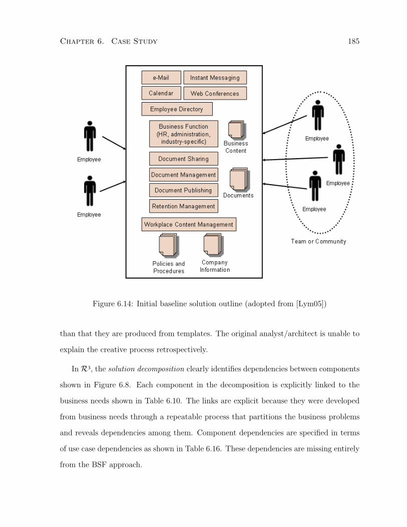
Chapter 6. Case Study 185
Figure 6.14: Initial baseline solution outline (adopted from [Lym05])
than that they are produced from templates. The original analyst/architect is unable to
explain the creative process retrospectively.
In R3, the solution decomposition clearly identifies dependencies between components
shown in Figure 6.8. Each component in the decomposition is explicitly linked to the
business needs shown in Table 6.10. The links are explicit because they were developed
from business needs through a repeatable process that partitions the business problems
and reveals dependencies among them. Component dependencies are specified in terms
of use case dependencies as shown in Table 6.16. These dependencies are missing entirely
from the BSF approach.

Chapter 6. Case Study 186
F1 Authentication and Authorization ServicesF2 Navigate and View WorkplaceF3 eMailF4 Instant Messaging (with awareness)F5 CalendarF6 Web ConferencesF7 Employee directoryF8 Task managementF9 Application Integration Services F10 Shared Work Area with document management F11 Workplace content managementF12 Life cycle management F13 Retention management F14 SearchF15 Content Repository ServicesF16 Minimal Desktop DeploymentF17 Adaptable infrastructure
Figure 6.15: Components of the baseline solution outline (adopted from [Lym05])
In addition, we identified additional use cases that were not in the BSF solution.
These include the 40 product-oriented use cases (with 3-digit ids) shown in Table 6.17.
We argue that because our process is repeatable and well guided, analysts can identify
these use cases more easily. In contrast, the ad hoc process used in BSF makes the
identification much less reliable.
We claim our candidate design is a better input to the design process than that of the
baseline because we provide a component layout, and explicit component and dependency
specifications in terms of use cases. The candidate design can be traced to each artifact
in the framework which facilitates the verification of requirements satisfaction.
The properties of the two approaches are summarized in Table 6.23.
6.4 Summary
This chapter described how R3 theory is applied to the industry case study, Employee
Workplace, showed how changes in requirements are handled, and provided a comparison
to an existing industry solution of the case study. In the next chapter, I present the

Chapter 6. Case Study 187
Table 6.23: Summary of properties exhibited in R3 and BSF
Properties Exhibited R3 Theory BSF
Decomposition means X
Dependency analysis X
Redundancy elimination X
NFR support X
Incremental X
Procedural X
Analysis means X
Template used X
Heuristics provided X
Process provided X X
Conceptual model X X

Chapter 6. Case Study 188
evaluation of the approach and compare to related work.

Chapter 7
Evaluation
Shaw indicates that novel research is commonly validated through illustrative examples
[Sha03a]. As the refactoring-based requirements refinement theory has no explicit prior
work, it can be validated mainly through an illustrative example, in this case, through
the application to an industry-size example (case study), Employee Workplace, described
in Chapter 6.
In this chapter, further evaluation is provided in two parts. First, an extensive crit-
ical analysis of R3 methods, challenges addressed, principles supported, and limitations
remaining are presented. Second, a comparison of the R3 theory to related work is
provided.
7.1 Validation via Critical Analysis
In this section, we provide an analytical validation of both the theory and the method
with respect to a set of criteria.
189

Chapter 7. Evaluation 190
7.1.1 Method Validation
Models and methods are typically assessed with respect to the following criteria [Gre06,
MS95, HMPR04]:
Completeness
The refinement model allows analysis on both abstract requirements (intentions and
business needs) and concrete functional descriptions in deriving an initial draft design in
its four-level refinement process.
The refactoring method, designed for this model, aims at eliminating redundancy,
identifying dependencies, decomposing requirements for different levels, and providing a
platform for design analysis. The method provides a diverse set of algorithms and oper-
ators for a designer to carry out the necessary refactoring. The operators are complete
relative to the algorithms. The algorithms are complete relative to the refinement process.
The method supports extension through additional dimension and heuristic definition for
analyzing context-specific design concerns and non-functional requirements.
Consistency
The consistency of a theory comes down to the consistency of its method. In our case,
it is the refactoring method, more specifically, the refactoring operators and algorithms.
The idempotence property of the operators and time bounds of the algorithms guaran-
tee termination. When dimensions are consistently defined, the method will not produce
contradictory results.
As discussed in Section 5.3.4.1, the specific analysis performed within each operator
is not part of the refactoring method. The consistency of results, or repeatability of
the method, therefore, comes down to the effect of the order, in which operators are
Chapter 7. Evaluation 191
applied in the method, assuming analysis is performed consistently in any given order.
The repeatability is not guaranteed by the method, but can be approximated. In other
words, the order of operators affects the outcome of the method, but is manageable.
It has been shown in Section 5.3.2.1 that all operators are associative, and operators
spp, asp, new, upd, gen, est, rlz, asf, spf, and dep are partially commutative under
the assumption that (~) the selector exists and precondition is satisfied in the prestate.
The listed operators are only applied in the algorithms when the assumption ~ holds.
Therefore, their commutativity within the scope of the algorithms is guaranteed by the
method.
Although operators ptn, con, mrg, xtr, and div are not commutative on their
own, the algorithms that apply them help achieve the repeatability, as shown below.
• ptn is applied only once in the method.
• con is applied following a total order in the method, thus the non-commutativity
will not affect its repeatability.
• mrg is repeatedly applied in Algorithm 2 until all redundancy is eliminated. If the
redundancy analysis is applied consistently, the result converges, thus achieving the
repeatability.
• xtr is repeatedly applied in Algorithm 2 until all overlaps across segments are
eliminated. If the overlap analysis is applied consistently, the result converges,
thus achieving the repeatability.
• div commutes within each multi-dimensional heuristic (proof is similar to that of
spp). The issue that affects the repeatability of the method is the order of applying
the heuristics, i.e., the choice of value of the dimension selector of the operator. This
issue is handled by Step 3 of Algorithm 3.

Chapter 7. Evaluation 192
Operator gnr is the only operator that is both non-commutative and the algorithm
applying it cannot help to achieve repeatability. However, the consistency of results con-
verges as the room for generalization and variation analysis diminishes after repeated
applications. In this way, the repeatability of the method can be achieved. Furthermore,
this operator is not designed for a meticulous analysis to reveal every possible gener-
alization and variation, but is meant to uncover the most obvious and critical cases of
generalization and variation.
At last, though defining dimensions is not a specific refactoring operator and has
no direct impact on intent preservation, the decision regarding which dimensions are
defined, and how, may significantly impact the repeatability of the method, especially
for operator ptn.
Simplicity
The operators, algorithms, and the process are minimal to achieve our goals.
Ease of Use
The refactoring method is intended to be performed manually by a designer. Given
that pseudo-code is presented, and guidelines are provided for the refinement process,
designers should find it easy to apply the method step by step.
Currently, there is no tool support. Although it may bring some convenience to users,
the benefit is not substantial.
Quality of Results
In comparison with the artifacts produced by experienced professionals in the same case
study (EW), the results obtained by applying the refinement and refactoring method
Chapter 7. Evaluation 193
defined in this dissertation are more traceable, decomposed more rationally, better struc-
tured, better reasoned, more clearly outlined with dependencies explicitly marked, free of
redundancy in description, and uncovered more implicit and hidden requirements. The
results prove that the method brings benefit to the design process, particularly during
the transition stage from requirements to design.
Interestingness
The R3 theory explicitly defines the relationship between refinement, decomposition, and
refactoring in the context of requirements engineering which has not been done in the
literature to date. Refinement is defined in the context of decomposition and refactoring,
and a model (framework) for applying the refinement, together with methods (based
on refactoring) are provided. Refactoring is defined, and operations and algorithms are
provided for the first time in the context of requirements engineering. The approach
encourages analyzing design concerns systematically during the requirements analysis
process through dimensions of concerns, and incorporates into requirements. The refine-
ment model allows requirements and design decisions to be better traced both to where
they originate and why they are selected.
7.1.2 Challenges Addressed
In this section, I discuss how my work addresses the challenges raised in Section 3.3.
Challenge 1 Architects need to take a broad range of design considerations and domain
knowledge into account in the design process. Tool support is desirable.
The dissertation work provides means for designers to take both the vertical dimen-
sion across different abstraction levels and the horizontal dimension spanning user and

Chapter 7. Evaluation 194
designer differences. Furthermore, refactoring dimensions are introduced to give designers
another level of freedom in expanding their design horizon.
Challenge 2 Considerations of functional and non-functional requirements need to be
intertwined rather than separated. This can be a tedious process.
The non-functional aspects are applied using various refactoring dimensions to the
functional requirements in the refinement process.
Challenge 3 Change is inevitable in software developments. Thus, anticipating changes
and designing accordingly is necessary. However, little is known about how to do this ef-
fectively and systematically.
My framework provides a structure for designers to carefully consider relevant pieces
of information and identify the relations between them easily. The traceability offered by
the framework can allow designers to take changes into account throughout the process,
and put more flexibility into design early on, to absorb further impact of changes.
Challenge 4 In practice, requirements are often filtered by middlemen. As a result,
key contextual information may be lost, which can mislead the architect in the design
process.
My framework is specifically designed for designers to work out the details in require-
ments, which helps reduce the chances of requirements misinterpretation.
Challenge 5 Architects need to negotiate with the customers directly to ensure the
requirements are feasible and consistent.
By working with my framework, designers are able to negotiate with customers, in-
volving more design-related details, but can still use a language of requirements.
Chapter 7. Evaluation 195
Challenge 6 Software architecture is multifaceted since individual stakeholders may
have different expectations that need to be addressed and problems clarified. Maintaining
the integrity of the multiple facets requires better tool support.
Although no physical tool is provided in this work, the methods introduced here (such
as refactoring dimensions, differentiating user and designer views, and working through
various abstraction levels) provide adequate means for designers to integrate multiple
facets of requirements while refining them into a design.
Challenge 7 Software architecture needs to be not only extensible, adaptable, abstract,
and elegant, but also marketable and have well-defined interfaces.
Part of the end results of the refinement process is a set of interfaces and components
of the system. These components are not made ad hoc or solely based on prior experience
and knowledge, but through a series of rationalized refinement analyses and refactoring.
Design principles such as separation of concerns, generality, abstraction, anticipation of
changes have been applied in the process, thus directly and indirectly enhancing the
extensibility, adaptability, abstraction, and elegance of the resulting design.
Challenge 8 Domain knowledge is considered essential in addressing the right problem
and making the right assumptions in design. Architects often employ tools and techniques
such as requirements management systems, code analysis software, and logic programming
in understanding the domain, context, and requirements. Further support in this area is
needed.
Domain knowledge can be incorporated into this dissertation work via addition of
domain-specific refactoring dimensions.

Chapter 7. Evaluation 196
Challenge 9 The transformation from requirements into architecture typically starts
from understanding the context and shaping the problem, then gets into structuring a
solution from the well-formed problem and existing reusable parts. Support in shaping
the problem and structuring a solution is needed.
The process provided in the framework is specifically designed to shape and structure
the problem in a refinement process.
In short, although the challenges have not been completely eliminated, in general,
this dissertation has provided an adequate solution to each challenge.
7.1.3 Principles Supported
The software engineering principles reviewed in Chapter 4 are supported by theR3 theory
as follows.
Separation of Concerns
• User and designer concerns are separately considered at the framework level.
• The refactoring methods are used to identify cohesion and coupling between prob-
lems, so that independent concerns are placed in separate components.
Modularity
• The decomposition represents the modularization which observes the interdepen-
dencies between problems and provides a high level of cohesion and decoupling.
Abstraction
• The R3 framework tolerate abstraction. Problems are expressed at an abstract
level before being refined into more specified requirements.

Chapter 7. Evaluation 197
• The framework supports different abstraction levels, taking the designer from the
more abstract overall system view to a more detailed component view.
Anticipation of Change
• Dimensions incorporate system-level properties which are refactored during the
refinement at domain level; thus, less impact will be made to the system level due
to change.
• Changes are more localized because the decomposition separates loosely-coupled
requirements and the dependencies are taken into account by the structure.
Generality
• Refactoring at component level specifically deals with generalization of functions.
• The dimensions are designed specifically to achieve generality, so that functions that
are repeatedly defined/invoked at many places are placed in one module rather than
repeated everywhere.
Incrementality
• The R3 framework has 4 stages where the analysis can be done incrementally from
stage to stage.
• Within each component of a system, the framework can be applied independently.
7.1.4 Limitations
There are two main limitations to this work. First, there is a deficit of empirical validation
to prove its value in software development. The Employee Workplace case study is used

Chapter 7. Evaluation 198
mostly as an illustrative example of how the requirements refinement and refactoring
framework and method can be applied. It also has a convenient alternative solution
(industry solution generated using the means in common practice), which can be used
to compare to the solution created by applying my method. This single case study
is insufficient to claim its general applicability empirically, which limits our ability to
claim further value of the method. To overcome this limitation, I plan to conduct future
studies on evaluation of requirements refinement and refactoring approach using other
case studies.
Second, there is a lack of tool support to this work. Requirements record human
needs in a system, which reside in the world that cannot be fully formalized. Require-
ments refinement is a bridging process between requirements (an informal artifact) and
design/program (formal product), and it heavily depends on human analysis. As such,
it cannot be completely automated because both the concepts and analysis cannot be
fully formalized. Therefore, tool support cannot provide complete automation to the
refinement process. However, there are benefits to having a tool: (i) instructional – users
can follow the instructions provided by the tool to ensure the framework and methods
are applied in an appropriate way; (ii) reduce workload – placeholders for the results of
each refactoring application and machine-identified overlaps can bring convenience to the
users and reduce workload; (iii) tracking – the evolution of the requirements through the
refinement and refactoring process can be recorded by the tool for reference and tracking
of how decisions are made. To leverage this limitation, I plan to construct a tool that
provides these benefits in the future.

Chapter 7. Evaluation 199
7.2 Comparison to Related Work
As Taylor and van der Hoek pointed out in their paper on the future of software de-
sign and architecture [TvdH07], design, as a bridge between the outer environment of
tasks (requirements, goals, and wants) and the inner environment of means (software lan-
guages, components, and tools), is the heart of software engineering. Current research
on software design and architecture emphasizes the structure and attributes of software
– components, connectors, and the constraints on their interactions, which is basically
the inner environment. On the other hand, research in requirements engineering focuses
on defining and specifying the problem domain (goals, needs, and desires). The task of
generating architectures to bridge the gap is often left to the skill and experience of the
architect.
The R3 Theory presented in this dissertation is a design method according to Taylor
and van der Hoek [TvdH07]. The related work selected below represents some of the
closest design methods to R3 Theory. They are feature-driven requirements dependency
analysis [ZMZ06], goal-oriented architecture derivation [vL03], Tropos [CKM01], and
AFrames [RHJN04]. An elaborated review of each related work is presented, followed by
a comparison with R3. Summary of the comparison is presented in Table 7.1.
7.2.1 Feature-driven Requirements Dependency Analysis
Zhang et al. propose a feature-driven approach that uses requirements dependency analy-
sis to design high-level software architecture [ZMZ06, ZMZ05, LM01]. In their approach,
requirements are defined as features.
Two aspects, intension and extension, are used to define a feature. In the for-
mer, a feature is a cohesive set of individual requirements. In the latter, a feature is
a user/customer-visible capability of a software system. Features are operationalized

Chapter 7. Evaluation 200
into a set of responsibilities which are to be assigned to developers.
Four kinds of dependency are defined between features: refinement, constraint, influ-
ence, and interaction.
• Refinement is a binary relation between features that composes features of different
levels of abstraction into hierarchical structures. This relation is further classified as
decomposition (part-whole ), characterization (entity-attribute), and specialization
(subclass).
• Constraint is a static dependency among features. It is used to customize re-
quirement and plan for release. Three constraint categories are identified: binary
constraints, group constraints, and complex constraints.
• Influence is a specification-level dependency between features. It imposes respon-
sibilities from one feature to another and reflects the responsibility assignment.
It can be used to analyze requirement changes or be a cause for the interaction
dependency.
• Interaction describes dynamic dependency between features, i.e., how features in-
teract with each other at run-time. Four kinds of interaction are presented: inform,
resourceconfigure, metalevel-configure, and flow.
Three kinds of connection between dependencies are defined to assist the identifica-
tion of feature dependencies: refinement and constraint, constraint and interaction, and
influence and interaction.
• Refinement-imposed constraints: refinements implicitly impose constraints on fea-
tures with respect to predefined rules.

Chapter 7. Evaluation 201
• Constraint and interaction: one-to-one relations between constraints and interac-
tions, where constraints are regarded as a static view of interactions and interactions
as a dynamic view of constraints.
• Influence and interaction: influence may cause additional responsibilities to be
assigned to features which may introduce additional interaction between features.
One key aspect of this approach is the customization of domain-specific reusable re-
quirements through binding resolution, i.e. to select features from the reusable feature
set. Detection of deficiencies (redundancy, anomalies, and inconsistency) in constraints
and binding resolutions is done with respect to predefined criteria in verifying the con-
sistency and completeness of the customization.
The results obtained from the above feature dependency analysis are used to design a
high-level software architecture – a set of computational elements and their interactions,
as follows:
• Resource container identification: to identify resource containers by analyzing de-
scriptions of or constraints on features. A resource container may directly define a
component, or combine with other responsibilities to form a component.
• Component seed creation: use responsibility containers related to features to define
seeds in component construction.
• Component construction: use heuristics to decide how to cluster component seeds
and/or resource containers into components.
• Interaction analysis: to identify interactions between components.
Chapter 7. Evaluation 202
7.2.2 Goal-oriented Architecture Derivation
Van Lamsweerde proposes a goal-oriented approach, based on the KAOS framework
[DvLF93, vL01], in modeling, specifying, and analyzing requirements to derive and refine
an architectural design [vL03]. This approach presents a refinement process that goes
from system goals to architecture in the following steps.
From system goals to software requirements
System goals, including functional and non-functional ones, are modeled in terms of
goal, object, agent, and operation in KAOS. Software requirements capture relations
between objects of the real world which are monitored and controlled by the software in a
vocabulary accessible to stakeholder. Operational (functional) software requirements are
derived from the system goals in four steps guided by heuristics and derivation patterns:
goal modeling, object modeling, agent modeling, and operationalization.
When multiple alternatives exist over subgoals, obstacle or conflict resolutions, and
agent assignments, decisions that influence the choice of architecture will be made.
From software requirements to software specifications
Software specifications are formulated in terms of objects manipulated by the software,
in a vocabulary accessible to programmers; they capture required relations between input
and output software objects. Software specifications are derived from requirements as
follows:
• Translate all goals assigned to software agents into the vocabulary of the software-
to-be by introducing software input-output variables;
• Map relevant elements of the (domain) object model to their images in the softwares
object model;

Chapter 7. Evaluation 203
• Introduce (non-functional) accuracy goals requiring the mapping to be consistent,
that is, the state of software variables and database elements must accurately reflect
the state of the corresponding monitored/controlled objects they represent;
• Introduce input/output agents to be responsible for such accuracy goals typically,
sensors, actuators or other environment agents.
From software specifications to abstract dataflow architectures
A dataflow architectural draft is derived from data dependencies among software agents
assigned to functional requirements where the agents become architectural components
statically linked through dataflow connectors. The procedure for the derivation is as
follows.
• For each functional goal, define a component composing the software agent dedi-
cated to the goal and its operations. The interface is defined by the set of variables
the agent monitors and controls.
• For each pair of components C1 and C2, derive a dataflow connector from C1 to C2
labeled with variable d iff d is among C1’s controlled variables and C2’s monitored
variables:
DataF low(d, C1, C2)⇔ Controls(C1, d) ∧Monitors(C2, d)
Style-based architecture refinement
The dataflow architecture is refined by imposing suitable architectural styles to meet the
architectural constraints modeled in the non-functional goals. To assist with the appli-
cation of styles, transformation rules can be defined, e.g., an event-based style transfor-
mation rule.

Chapter 7. Evaluation 204
Pattern-based architecture refinement
The style-based architecture is further refined to achieve other non-functional goals:
quality-of-service goals and development goals (referred to as NFGs). This refinement
step works on a local basis, either within a pair of components (connector refinement)
or a single component (component refinement). Architectural refinement patterns are
defined for common NFGs. The procedure is as follows:
• For each terminal NFG in the goal refinement graph G, identify all specific connec-
tors and components NFG may constrain and instantiate NFG to those connectors
and components (if necessary).
• For each NFG-constrained connector or component, refine it to meet the instanti-
ated NFGs associated with it. Apply the NFG architectural refinement patterns to
drive the refinement.
7.2.3 Tropos
Tropos [CKM01] offers a notion, consisting actor, goal, tasks, and dependencies between
actors, to model early and late requirements, and architectural and detailed design. It
uses i∗ [Yu95] to capture early requirements as an organizational model, elaborate them
through late requirements analysis to provide relevant functions and qualities in the
operational environment, use the captured NFRs (non-functional requirements) to guide
selection of architecture style and actor decomposition. This approach also proposes to
generate an agent-oriented programming implementation.
Tropos presents three phases to go from requirements to architecture. It also discusses
how to integrate with existing methods in low-level design and implementation.

Chapter 7. Evaluation 205
Early Requirements Analysis Phase
In this phase, requirements engineers describe the dependencies, in terms of goals, tasks,
and resources, between social actors in an i∗ strategic dependency model, and model
the goal fulfillments by postulating tasks and goals through means-ends analysis using
process decomposition and means-ends links in an i∗ strategic rationale model.
The purpose of early requirements analysis phase is to identify the needs of the system-
in-interest in relation to the organizational structure, various stakeholder, and existing
system components. However, for independent systems or those with few stakeholder
where the need is already identified, applying the early requirements analysis adds little
value.
Late Requirements Analysis Phase
In this phase, requirements engineers introduce system actors into both the strategic
dependency model and strategic rationale model, update the dependencies and goal ful-
fillments, decompose the system actors into subactors and make an assignment of respon-
sibilities, and form all of the functional and non-functional requirements specifications
from the tasks and dependencies (some may be postponed to later stage).
The models are produced using generic means-ends analysis. The decomposition of
system actor and the subsequent assignment of responsibilities are left to the designer’s
own device as no guidance is provided.
Architectural Design Phase
In this phase, software architects build a softgoal refinement model based on NFRs to
evaluate and compare softgoals’ operationalization of each potential architectural style,
and further update the strategic dependency model with new system actors or decom-
Chapter 7. Evaluation 206
positions of existing actors.
The method does not make it clear how to carry out further decomposition when few
non-functional requirements are present. Furthermore, the method provides no means to
analyze how the distribution of responsibilities should be made in the chosen architectural
style.
Integration to Existing Methods
In the detailed design phase, designers are suggested to model details, such as actor com-
munication and behavior for each architectural component, using existing agent commu-
nication language such as AUML (Agent Unified Modeling Language).
Finally, the method also recommends developers to use an agent-oriented development
environment, such as JACK, to generate implementation of the system.
7.2.4 Architectural Frames
Problem Frames [Jac01] capture generic problem patterns which provide a means to
analyze and decompose problems while delaying consideration of the solution space until
a good understanding of the problem is gained. We have reviewed this body of work in
Chapter 2.
The architectural frames (AFrames) approach [RHJN04] extends problem frames by
combining an architectural style to facilitate problem analysis, decomposition, and re-
composition.
An AFrame captures the reconciliation of a problem frame and an architectural style.
For example, a pipe-and-filter transformation AFrame is defined as the reconciliation of
the Transformation Frame and Pipe-and-Filter architectural style. An AFrame consists
of a set of decomposition templates identifying subproblems for considerations. The

Chapter 7. Evaluation 207
recomposition of a solution from the subproblems relies on the frame concern defined for
the reconciled problem frame.
To use AFrame, a designer must first recognize which problem frame is appropriate
for the problem at hand and commit to an architectural style. If a change to either the
choice of problem frame or architectural style incurs, a designer must redo all the work
by using the new AFrame. This approach, therefore, is not incremental.
To have a complete method built on AFrames, there has to be either an exhaustive set
of AFrames defined for every combination of existing problem frames and architectural
styles, or means to construct and define AFrames given problem frames and architectural
styles. Neither of these options is available right now. Furthermore, a system may require
to use more than one problem frame to represent its requirements. It is unclear how this
can be done in the AFrames approach.
7.2.5 Comparisons
The criteria of the comparisons are defined to represent the properties exhibited and
the value offered by the methods. They are listed in Table 7.1. The comparisons are
discussed below.
• The feature-driven approach provides a rich set of dependency types which allows
users to analyze relationships between requirements, but it provides no guidance or
process to help carry out the analysis. It offers no specific ways to deal with NFRs.
• Goal-based architecture derivation approach offers a complete process for going
from system goals to architecture. The extensive research on the KAOS framework
provides means for goal decomposition, refinement, and conflict resolution. General
heuristics are provided in using these means, without specific guidance in analysis.

Chapter 7. Evaluation 208
• Tropos proposes an integration of existing notations used in various development
stages and combines with an existing method and development environment to
make a detailed design and generate an implementation. The composition of ex-
isting notations for different phases suggests a refinement process, but no specific
method is provided for most of the analysis involved, except to use a generic means-
ends analysis. Specifically, no rationale is given for the decomposition of system
actors into subactors and the subsequent assignment of responsibilities, as they
are performed to the liking of the designer. Given such freedom of choice, few
designers will actually document the rationale, resulting in the loss of traceable
decision-making reasoning.
On the other hand, theR3 approach provides a refinement process with well-defined
algorithms and refactoring operators in analyzing the given requirements (stated as
problems) to produce a system decomposition. Furthermore, decisions made about
each decomposition choice can be traced to the specific algorithms and operators
while the design history is documented, which makes it easier to trace the type of
analysis and decisions made.
Tropos suggests using AUML and JACK for detailed design and implementation,
which at the same time imposes a limitation on the designers’ choices.
The R3 approach is specifically designed to address the transition issues involved
in going from requirements to architecture, specifically in designing a system lay-
out. It does not include a method for low-level design and implementation phases.
Nonetheless, a generic method, such as Rational Unified Process (RUP) together
with the Unified Modeling Language (UML), can be adopted in these phases. Fur-
thermore, there is no restriction on which language to use in the implementation,
thus giving the designer a wider range of choices.

Chapter 7. Evaluation 209
Table 7.1: Summary of comparison in properties exhibited and values offered
Exhibited Properties R3 Theory Feature Goal Tropos AFrame
Decomposition means X X X X
Dependency analysis X X X
Redundancy elimination X X
NFR support X X X
Incremental X X
Procedural X
Analysis means X X
Pattern/template used X X X
Heuristics provided X X X X
Process provided X X X
Conceptual model X X X
• AFrames offer a pattern-based approach that combines problem frames with ar-
chitectural styles. It offers no guidance or process. Currently, it is incomplete, as
neither an exhaustive set of AFrames is defined for every combination of existing
problem frames and architectural styles, nor is any means provided to construct
and define AFrames, given problem frames and architectural styles.
7.3 Summary
This chapter presented further evaluation of the R3 theory as follows: method validation,
discussion of challenges addressed, principles supported, and limitations remaining, and
comparison to related work.

Chapter 8
Conclusions
In this dissertation, I have presented a refactoring-based refinement theory that consists
of a refinement framework and refactoring methods. Sixteen refactoring operators and six
algorithms are defined as a platform to help designers carry out analysis of requirements
towards design. The framework identifies four requirements abstraction levels, separates
the user and designer stance, and introduces six phases to help designers refine a set
of high-level business requirements into a structured requirements decomposition, as an
initial draft design for the subsequent design phase.
The research contributions and further research are described below.
8.1 Research Contributions
The contributions of this dissertation comprise three parts: collection of empirical ev-
idence; a theory defining the roles of refinement, refactoring, and decomposition in re-
quirements context; and a method for applying refactoring to requirements in obtaining
decomposition, following a refinement process.
210

Chapter 8. Conclusions 211
Collection of Empirical Evidence
• Report of needs and further challenges in a COTS-based approach to tackling the
boundary problem.
• Report of key findings from software architects that address the boundary problem.
• Survey of the use of decomposition, refactoring, and refinement in requirements and
software engineering.
A Theory of Requirements Refinement, Refactoring, and De-
composition
• Explicitly define refinement, decomposition, refactoring, and their relationships in
the requirements analysis context.
• Establish the meaning of refactoring for requirements in the context of software
refactoring, and its relation to requirements decomposition and refinement.
• Establish the need for architecting (or designing) requirements and demonstrate its
feasibility.
• Model, and reason about, user concerns and designer expectations in requirements
separately at appropriate abstraction levels.
• Provide a novel paradigm of requirements abstraction levels, which facilitates the
transition from problem domain to solution domain.
• Provide a novel framework and methodology adhering to the theory that exploits
the aforementioned paradigm in establishing an early conceptual design from the
requirements.

Chapter 8. Conclusions 212
• Provide a novel approach in going from requirements to design.
A Method of Requirements Refactoring
• Use dimensions to capture and define design concerns (cross-cutting concerns and
non-functional requirements) that are necessary to analyze requirements. Define
five dimension heuristics capturing common design concerns.
• Introduce requirements refactoring operators and algorithms in the refinement frame-
work to guide designers to incorporate design concerns into requirements systemat-
ically.
• Derive requirements decomposition systematically from requirements, observing and
revealing the dependency between requirements.
8.2 Further Research
This research can be extended in a number of ways. First, the framework and methods
can be further validated by applying to other case studies. Furthermore, empirical studies
can be conducted to measure and compare the effort and workload of the approach in
contrast to the benefits it brings.
Second, the framework and methods can be extended to be more widely applica-
ble. This can be achieved from several aspects: (i) develop additional heuristics and
extend the choice of dimensions to be used in common refactoring needs; (ii) provide
domain-specific support by defining relevant dimensions and refactoring algorithms, so
that refactoring method can be more commonly accepted and widely applicable; and (iii)
provide refactoring means towards evolution-related concerns.
Chapter 8. Conclusions 213
Third, architectural styles and design patterns are commonly used tools in design.
Given that candidate designs produced from refactoring are the first design product from
requirements, it can be useful to designers if a mechanical mapping can be established
between candidate design and architectural styles or design patterns. Further research
in this area is desirable.
Fourth, tool support can be provided for the following purposes: (i) instruction —
users can follow the instructions provided by the tool to ensure the framework and method
are applied in an appropriate way; (ii) reducing workload – maintaining a collection of
all artifacts produced and automatically identifying overlaps brings more convenience
to designers and reduces their workload; (iii) tracking – keeping a history log of each
applied operation provides a complete record of how design decisions are made and how
requirements evolve in the R3 process.
Fifth, more specific studies on how R3 interacts with elicitation methods in the Do-
main Description phase can better assist designers in extracting functions, and broaden
the applicability of R3.
Last, we can explore properties that make requirements design-ready and provide a
quantification scheme for measurement.

Bibliography
[AM00] Enrique Garcıa Alcazar and Antonio Monzon. “A Process Framework for
Requirements Analysis and Specification”. In ICRE ’00: Proceedings of the
4th International Conference on Requirements Engineering (ICRE’00), pages
27–38, 2000.
[Arn89] R.S. Arnold. “Software Restructuring”. Proceedings of the IEEE, 77(4):607–
617, 1989.
[BC99] Carliss Y. Baldwin and Kim B. Clark. “Design Rules: The Power of Modu-
larity Volume 1”. MIT Press, Cambridge, MA, USA, 1999.
[BCM03] Lucia Bastos, Jaelson Castro, and John Mylopoulos. “Integrating Organi-
zational Requirements and Socio-Intentional Architectural Styles”. 2003. In
[str03].
[BK87] J. Banerjee and W. Kim. “Semantics and Implementation of Schema Evolu-
tion in Object-Oriented Databases”. ACM SIGMOD, 1987.
[Boe88] Barry W. Boehm. “A Spiral Model of Software Development and Enhance-
ment”. IEEE Computer, 21(5):61–72, May 1988.
214
Bibliography 215
[BP01] Manuel Brandozzi and Dewayne E. Perry. “Transforming Goal Oriented
Requirement Specifications into Architecture Prescriptions”. pages 54–60.
2001. In [str01].
[BP02] Manuel Brandozzi and Dewayne E. Perry. “Architectural Prescriptions for
Dependable Systems”. In Proceedings of ICSE 2002 Workshop on Architect-
ing Dependable Systems, pages 54–60. 2002.
[BP03] Manuel Brandozzi and Dewayne E. Perry. “From Goal-Oriented Require-
ments to Architectural Prescriptions: The Preskriptor Process”. pages 107–
113. 2003. In [str03].
[BPG+01] Paolo Bresciani, Anna Perini, Paolo Giorgini, Fausto Giunchiglia, and John
Mylopoulos. “Modeling Early Requirements in Tropos: A Transformation
Based Approach”. In AOSE ’01: Revised Papers and Invited Contributions
from the Second International Workshop on Agent-Oriented Software Engi-
neering II, pages 151–168, 2001.
[BPG+04] Paolo Bresciani, Anna Perini, Paolo Giorgini, Fausto Giunchiglia, and John
Mylopoulos. Tropos: An agent-oriented software development methodology.
Autonomous Agents and Multi-Agent Systems, 8(3):203–236, 2004.
[BR89] B. W. Boehm and R. Ross. “Theory W Software Project Management: Prin-
ciples and Examples”. IEEE Transactions on Software Engineering, pages
902–916, 1989.
[BRJ00] Grady Booch, James Rumbaugh, and Ivar Jacobson. “The Unified Modeling
Language User Guide”. Addison Wesley, 2000.

Bibliography 216
[CC90] E.J. Chikofsky and J.H. Cross. “Reverse Engineering and Design Recovery:
A Taxonomy”. IEEE Software, 7(1):13–17, 1990.
[CKK01] Paul Clements, Rick Kazman, and Mark Klein. “Evaluating Software Archi-
tectures”. Addison-Wesley, 2001.
[CKM01] Jaelson Castro, Manuel Kolp, and John Mylopoulos. “A Requirements-
Driven Development Methodology”. In CAiSE’01, 2001.
[CNYM00] L. Chung, B.A. Nixon, E. Yu, and J. Mylopoulos. “Non-Functional Require-
ments in Software Engineering”. Kluwer Academic Publishers, 2000.
[Dro03] Geoff Dromey. “Architecture as an Emergent Property of Requirements In-
tegration”. pages 77–84. 2003. In [str03].
[DvL96] R. Darimont and A. van Lamsweerde. “Formal Refinement Patterns for Goal-
Driven Requirements Elaboration”. In Proceedings FSE-4 - 4th ACM Symp.
on the Foundations of Software Engineering, pages 179–190, 1996.
[DvLF93] Anne Dardeene, Axel van Lamsweerde, and Stephen Fickas. “Goal-Directed
Requirements Acquisition”. Science of Computer Programming, 20:3–50,
1993.
[Eas91] Steve Easterbrook. “Elicitation of Requirements from Multiple Perspectives”.
PhD thesis, University of London, Imperial College of Science, Technology
and Medicine, 1991.
[EGM01] Alexander Egyed, Paul Grunbacher, and Nenad Medvidovic. “Refinement
and Evolution Issues in Bridging Requirements and Architecture - The CBSP
Approach”. pages 42–47. 2001. In [str01].

Bibliography 217
[EYA+05] S. M. Easterbrook, E. Yu, J. Aranda, Y. Fan, J. Horkoff, M. Leica, and R. A.
Qadir. “Do Viewpoints Lead to Better Conceptual Models? An Exploratory
Case Study”. In Proceedings of the 13th IEEE International Conference on
Requirements Engineering, 2005.
[Fow99] Martin Fowler. “Refactoring: Improving the Design of Existing Programs”.
Addison-Wesley, 1999.
[Gar00] David Garlan. “Software Architecture: a Roadmap”. In ICSE - Future of
SE Track, pages 371–380, 2000.
[GEM01] Paul Grunbacher, Alexander Egyed, and Nenad Medvidovic. “Reconciling
Software Requirements and Architectures: The CBSP Approach”. In Pro-
ceedings of the 5th IEEE International Symposium on Requirements Engi-
neering, pages 202–211, 2001.
[GEM04] Paul Grunbacher, Alexander Egyed, and Nenad Medvidovic. “Reconciling
Software Requirements and Architectures with Intermediate Models”. Jour-
nal for Software and System Modeling (SoSyM), 3(3):235–253, 2004.
[GF94] Orlena C.Z. Gotel and Anthony C.W. Finkelstein. “An Analysis of the Re-
quirements Traceability Problem”. In Proceedings of the First International
Conference on Requirements Engineering, pages 94–101, 1994.
[GHJV95] Erich Gamma, Richard Helm, Ralph Johnson, and John Vlissides. “Design
Pattern Elements of Reusable Object Oriented Software”. Addison-Wesley,
1995.
[GJM03] Carlo Ghezzi, Mehdi Jazayeri, and Dino Mandrioli. “Fundamentals of Soft-
ware Engineering” 2nd Ed. Prentice Hall, 2003.

Bibliography 218
[GKN92] David Garlan, Gail E. Kaiser, and David Notkin. “Using Tool Abstraction
to Compose Systems”. Computer, 25(6):30–38, 1992.
[Gre06] Shirley Gregor. “The Nature of Theory in Information Systems”. MIS Quar-
terly, 30(3):611–642, 2006.
[GS99] Barney G. Glaser and Anselm L. Strauss. “The Discovery of Grounded The-
ory: Strategies for Qualitative Research”. New York: Aldine, 1999.
[Heh93] Eric C.R. Hehner. “a Practical Theory of Programming”. Springer, 1993;
current edition free at www.cs.utoronto.ca/∼hehner/aPToP.
[HJL+02] Jon G. Hall, Michael Jackson, Robin C. Laney, Bashar Nuseibeh, and Lu-
cia Rapanotti. “Relating Software Requirements and Architectures using
Problem Frames”. In Proceedings of IEEE International Requirements Engi-
neering Conference (RE’02), September 2002.
[HLK95] C.L. Heitmeyer, B. Labaw, and D. Kiskis. “Consistency Checking of SCR-
Style Requirements Specifications”. In Proceedings of the 2nd Symposium on
Requirements Engineering, pages 27–29, 1995.
[HMPR04] Alan R. Hevner, Salvatore T. March, Jinsoo Park, and Sudha Ram. “Design
Science in Information Systems Research”. MIS Quarterly, 28(1):75–105,
2004.
[Hoa85] C. A. R. Hoare. “Communicating Sequential Processes”. Englewood Cliffs.
NJ: Prentice-Hall lnternational, 1985.
[Hua87] J. C. Huang. “A Depth-first and Tool-supportable Programming Strategy”.
Software, Practice and Experience, 17(2):159–163, 1987.

Bibliography 219
[HY88] P. Hsia and A. T. Yaung. “Another Approach to System Decomposition”.
In IEEE Proceedings of COMPSAC’88, pages 75–82, 1988.
[Jac96] Michael Jackson. “Software Requirements and Specifications”. Addison-
Wesley, 1996.
[Jac97] Michael Jackson. “The Meaning of Requirements”. Annals of Software En-
gineering, 3:5–21, 1997.
[Jac00] Michael Jackson. “Problem Analysis and Structure”. Engineering Theories
of Software Construction — Proceedings of NATO Summer School, Markto-
berdorf, pages 3–20, 2000.
[Jac01] Michael Jackson. “Problem Frames: Analysing and Structuring Software
Development Problems”. Addison-Wesley, 2001.
[JJ96] D. Jackson and M. Jackson. “Problem Decomposition for Reuse”. IEE/BCS
Software Engineering Journal, 11(1):19–30, 1996.
[KCAB96] R. Kazman, P. Clements, G. Abowd, and L. Bass. “Classifying Architectural
Elements as a Foundation for Mechanism Matching”. In ACM SIGSOFT
Symposium on the Foundations of Software Engineering, 1996.
[KCM01] Manuel Kolp, Jaelson Castro, and John Mylopoulos. “A Social Organization
Perspective on Software Architectures”. 2001. In [str01].
[Kir98] David P. Kirkman. “Requirement Decomposition and Traceability”. In Pro-
ceedings of the International Conference on Requirements Engineering, pages
107–114, 1998.
[Koy92] R. Koymans. “Specifying Message Passing and Time-Critical Systems with
Temporal Logic”. Springer-Verlag, 1992.

Bibliography 220
[Kru00] Philippe Kruchten. “The Rational Unified Process An Introduction Second
Edition”. Addison Wesley, 2000.
[LCLP05] WenQian Liu, Charles L. Chen, Vidya Lakshminarayanan, and Dewayne E.
Perry. “A Design for Evidencebased Software Architecture Research”. In
Proceedings of the REBSE05 co-located with ICSE’05, May 2005. St. Louis,
Missouri, USA.
[LE03] WenQian Liu and Steve Easterbrook. “Eliciting Architectural Decisions from
Requirements using a Rule-based Framework”. pages 94–99. 2003. In [str03].
[LEM02] WenQian Liu, Steve Easterbrook, and John Mylopoulos. “Rule-Based De-
tection of Inconsistency in UML Models”. In Proceeding of the Workshop on
Consistency Problems in UML-Based Software Development at the�UML�
Conference, 2002.
[Lev98] Nancy Leveson. “Intent Specifications: An Approach to Building Human-
Centered Specifications”. In Proceedings of the 3rd International Conference
on Requirements Engineering (ICRE), pages 204–213, 1998.
[Lev00] Nancy Leveson. “Intent Specifications: An Approach to Building Human-
Centered Specifications”. IEEE Transactions on Software Engineering, 26(1),
2000.
[Lev03] Nancy Leveson. “Toward a Science of Software Design”. In Proceedings of the
Workshop on Science of Design: Software and Software-Intensive Systems,
Nov. 2003.
Bibliography 221
[Liu02] WenQian Liu. “Rule-based Detection of Inconsistency in Software Design”.
Master’s thesis, University of Toronto, Department of Computer Science,
July 2002.
[Liu04] WenQian Liu. “Architecting Requirements”. In Proceeding of the Doctoral
Consortium at RE’04, 2004. Kyoto, Japan.
[Liu05] WenQian Liu. “Requirements Decomposition, Refinement and Refactoring :
A Survey”. Technical report, University of Toronto (Canada), Department
of Computer Science, September 2005.
[Liu08] WenQian Liu. “A Requirements Refinement Framework”. In Proceedings of
SAC’08, March 2008.
[LLC+06] Vidya Lakshminarayanan, WenQian Liu, Charles L Chen, Steve Easterbrook,
and Dewayne E Perry. “Software Architects in Practice: Handling Require-
ments”. In Proceedings of CASCON’06, 2006.
[LLCP05] Vidya Lakshminarayanan, WenQian Liu, Charles L Chen, and Dewayne E
Perry. “Digest of Interview Data”. Technical report, University of Texas,
July 2005.
[LLCP06] Vidya Lakshminarayanan, WenQian Liu, Charles L Chen, and Dewayne E
Perry. “A Case Study of Architecting Security Requirements in Practice:
Initial Analysis”. Technical report, University of Texas, July 2006.
[LLE05] Sharon Lymer, WenQian Liu, and Steve Easterbrook. “Experience in Using
Business Scenarios to Assess COTS Components in Integrated Solutions”. In
Proceedings of the CASCON’05, Best Paper Award. October 2005.
Bibliography 222
[LM01] Dongyun Liu and Hong Mei. “Mapping Requirements to Software Architec-
ture by Feature-orientation”. pages 69–76, 2001. In [str01].
[Lym05] Sharon Lymer. “Employee Workplace Vision” (v1.5). IBM Business Scenario
Documentations, 2005.
[MCN92] John Mylopoulos, Lawrence Chung, and Brian Nixon. “Representing and
Using Nonfunctional Requirements: a Process-oriented Approach”. IEEE
Transactions on Software Engineering, 18(6):488–497, 1992.
[mda03] “MDA Guide” (OMG v1.0.1). http://www.omg.org/mda/, 2003.
[Moo90] A. P. Moore. “The Specification and Verified Decomposition of System
Requirements Using CSP”. IEEE Transactions on Software Engineering,
16(9):932–948, 1990.
[MS95] Salvatore T. March and Gerald F. Smith. “Design and Natural Science Re-
search on Information Technology”. Decision Support Systems, 15:251–266,
1995.
[MT04] T. Mens and T. Tourwe. “A Survey of Software Refactoring”. IEEE Trans-
actions on Software Engineering, 30(2):126–139, 2004.
[NE00] Bashar Nuseibeh and Steve Easterbrook. “Requirements Engineering: a
Roadmap”. In ICSE - Future of SE Track, pages 35–46, 2000.
[NF92] Bashar Nuseibeh and Anthony Finkelstein. “ViewPoints: A Vehicle for
Method and Tool Integration”. In Proceedings of the 5th International Work-
shop on Computer-Aided Software Engineering (CASE ’92), pages 50–60,
1992.

Bibliography 223
[Nus94] Bashar Ahmad Nuseibeh. “A Multi-Perspective Framework for Method In-
tegration”. PhD thesis, University of London, Imperial College of Science,
Technology and Medicine, 1994.
[Opd92] W. F. Opdyke. “Refactoring: A Program Restructuring Aid in Designing
Object-Oriented Application Frameworks”. PhD thesis, University of Illinois
at Urbana-Champaign, 1992.
[Ope01] Open Group. Guidelines on Business Scenarios. http://www.opengroup.
org/architecture/togaf7-doc/arch/p4/bus_scen/bus_scen.htm, 2001.
[Par71] David Lorge Parnas. “Information Distribution Aspects of Design Method-
ology”. In IFIP Congress (1), pages 339–344, 1971.
[Par72] D. L. Parnas. “On the Criteria to be Used in Decomposing Systems into
Modules”. Communications of the ACM, 15(12):1053–1058, Dec. 1972.
[PdW04] Eltjo R. Poort and Peter H.N. de With. “Resolving Requirement Conflicts
through Non-Functional Decomposition”. In Proceedings of the 4th Working
IEEE IFIP Conference on Software Architecture (WICSA 2004), 2004.
[Pre94] W. Pree. “Meta Patterns – A Means for Capturing the Essentials of Reusable
Object-Oriented Design”. In ECOOP 94, 1994.
[PTA94] Colin Potts, Kenji Takahashi, and Annie I. Anton. ‘Inquiry-Based Require-
ments Analysis’. IEEE Software, 11(2):21–32, 1994.
[RHJN04] Lucia Rapanotti, Jon G. Hall, Michael Jackson, and Bashar Nuseibeh.
“Architecture-driven Problem Decomposition”. In Proceedings of 12th IEEE
International Requirements Engineering Conference (RE’04), September
2004.

Bibliography 224
[RJ01] Balasubramaniam Ramesh and Matthias Jarke. Toward reference models
for requirements traceability. IEEE Transactions on Software Engineering,
27(1):58–93, 2001.
[RNK98] A. Russo, B. Nuseibeh, and J. Kramer. “Restructuring Requirements Spec-
ifications for Managing Inconsistency and Change: A Case Study”. In Pro-
ceedings of the International Conference on Requirements Engineering, pages
51–61, 1998.
[RNK99] A. Russo, B. Nuseibeh, and J. Kramer. “Restructuring Requirements Speci-
fications”. IEE Proceedings: Software, 146(1):44–53, 1999.
[Rob99] D. Roberts. “Practical Analysis for Refactoring”. PhD thesis, University of
Illinois at Urbana-Champaign, 1999.
[Roy70] Winston Royce. “Managing the Development of Large Software Systems”.
In Proceedings of IEEE WESCON, 1970.
[SC96] Mary Shaw and Paul Clements. “A Field Guide to Boxology: Preliminary
Classification of Architectural Styles for Software Systems”. Working Paper,
Internet Publication, 1996.
[SFT99] George Spanoudakis, Anthony Finkelstein, and David Till. “Overlaps in
Requirements Engineering”. Automated Software Engineering, 6(2):171–198,
1999.
[SG96] Mary Shaw and David Garlan. “Software Architecture: Perspectives on an
Emerging Discipline”. Prentice Hall, 1996.
Bibliography 225
[Sha01] Mary Shaw. “The Coming-of-age of Software Architecture Research”. In
Proceedings of the 23rd International Conference on Software Engineering,
page 656, 2001.
[Sha03a] Mary Shaw. “Writing Good Software Engineering Research Papers: Mini-
tutorial”. In Proceedings of the 25th International Conference on Software
Engineering, pages 726–736, 2003.
[Sha03b] Mary Shaw. “Research Questions for Foundations of Complex Software De-
sign”. In Proceedings of the Workshop on Science of Design: Software and
Software-Intensive Systems, Nov. 2003.
[Sim96] Herbert A. Simon. “The Sciences of the Artificial”, 3rd Edition. MIT Press,
Cambridge, MA, USA, 1996.
[SPLJ01] G. Sunye, D. Pollet, Y. LeTraon, and J.-M. Jezequell. “Refactoring UML
Models”. In Proceedings of the Unified Modeling Language Conference, 2001.
[str01] In Jaelson Castro and Jeff Kramer, editors, “The First International Work-
shop on From Software Requirements to Architectures (STRAW’01)”. 2001.
At the 23rd International Conference on Software Engineering, Toronto.
[str03] In Daniel M. Berry, Rick Kazman, and Roel Wieringa, editors, “The
Second International Software Requirements to Architectures Workshop
(STRAW’03)”. 2003. At the 25rd International Conference on Software En-
gineering, Portland USA.
[Sve03] Davor Svetinovic. “Architecture-Level Requirements Specification”. pages
14–19. 2003. In [str03].

Bibliography 226
[TB99] Lance Tokuda and Don Batory. “Evolving Object-Oriented Designs with
Refactorings”. In Proceedings of Automated Software Engineering, pages 174–
181, 1999.
[TvdH07] Richard N. Taylor and Andre van der Hoek. “Software Design and Archi-
tecture – The once and future focus of software engineering”. In ICSE’07,
Future of SE. 2007.
[Vic99] Kim J. Vicente. “Cognitive Work Analysis”. LEA, 1999.
[vL00] Axel van Lamsweerde. “Requirements Engineering in the Year 00: A Re-
search Perspective”. In Proceedings of the 22nd International Conference on
Software Engineering - Invited Paper, 2000.
[vL01] Axel van Lamsweerde. “Goal-Oriented Requirements Engineering: A Guided
Tour”, invited minitutorial. In Proceedings of the 5th IEEE International
Symposium on Requirements Engineering, pages 249–263, 2001.
[vL03] Axel van Lamsweerde. “From System Goals to Software Architecture”. In
M. Bernardo and P. Inverardi, editors, Formal Methods for Software Archi-
tectures, pages 25–43, 2003.
[vLBLJ03] Axel van Lamsweerde, Simon Brohez, Renaud De Landtsheer, and David
Janssens. “From System Goals to Intruder Anti-Goals: Attack Generation
and Resolution for Security Requirements Engineering”. In Proceedings of
the Requirements for High Assurance Systems Workshop (RHAS’03), 2003.
[vLDL98] A. van Lamsweerde, R. Darimont, and E. Letier. “Managing Conflicts in
Goal-Driven Requirements Engineering”. IEEE Transactions on Software
Engineering, 24(11):908–926, 1998.

Bibliography 227
[vLL00] A. van Lamsweerde and E. Letier. “Handling Obstacles in Goal-Oriented
Requirements Engineering”. IEEE Transactions on Software Engineering:
Special Issue on Exception Handling, 26(10):978–1005, 2000.
[Whi04] Stephen A. White. “Introduction to BPMN”. www.bptrends.com, July 2004.
[Yau92] Alan T. Yaung. “Design and Implementation of a Requirements Clustering
Analyzer for Software System Decomposition”. In Hal Berghel, Ed Deaton,
George Hedrick, David Roach, and Roger Wainwright, editors, Proceedings
of the Symposium on Applied Computing. Volume 2, pages 1048–1054, Mar
1992.
[YM00] Eric S.K. Yu and John Mylopoulos. “AI Models for Business Process Reengi-
neering”. In Proceedings of the Third International Conference on UML,
2000.
[Yu95] Eric Yu. “Modelling Strategic Relationships for Process Reengineering
(Agents, Goals)”. PhD thesis, University of Toronto (Canada), Department
of Computer Science, 1995.
[Yu97] Eric S.K. Yu. “Towards Modeling and Reasoning Support for Early-Phase
Requirements Engineering”. In Proceedings of the Third IEEE International
Symposium on Requirements Engineering, pages 226–235, 1997.
[ZJ97] Pamela Zave and Michael Jackson. “Four Dark Corners of Requirements
Engineering”. ACM Transactions on Software Engineering and Methodology
(TOSEM), 6(1):1–30, 1997.
[ZMZ05] Wei Zhang, Hong Mei, and Haiyan Zhao. “A Feature-Oriented Approach to
Modeling Requirements Dependencies”. In Proceedings of RE’05, 2005.

Bibliography 228
[ZMZ06] Wei Zhang, Hong Mei, and Haiyan Zhao. “Feature-driven Requirement De-
pendency Analysis and High-level Software Design”. Requirements Engineer-
ing Journal, 11(3), 2006.

Appendix A
Questionnaire – On the Meaning of
Software Architecture
A.1 Problem Domain
A.1.1 Describe the problem domain(s) that you have been working in.
• General domain
• Specific domain examples
A.1.2 What are the characteristics in each domain?
• Mature vs. immature
– Mature - established business process; well defined theory, processing and
expected behaviors; well understood objects
• Stable vs. unstable
– Degree or constancy of change during and after development
229

Appendix A. Questionnaire – On the Meaning of Software Architecture230
• Physical vs. intellectual
– Physical as for embedded systems etc.
– Intellectual as for mathematical and computational software such as web ser-
vices
• Level of automation
– Automated vs. manual
– Sophistication and quality of the automation
A.1.3 What effects does the domain have on requirements and architecture?
A.1.4 Coverage of domain
• General purpose vs. specific purpose
• General users/uses vs. specific users/uses
A.2 Overview of Software Architecture
This section is to capture the architect’s general understanding of software architecture
and its meaning and significance to the system.
A.2.1 What do you consider to be the critical characteristics of software architecture?
• What is the essence of software architecture?
• How many levels of architecture are there? How detailed should it be? Should it
be prescriptive or descriptive?
• What would the architectural representation include?

Appendix A. Questionnaire – On the Meaning of Software Architecture231
• How do you communicate an architecture to the stakeholders?
A.2.2 What are the critical aspects and characteristics of a great/superb software ar-
chitect?
• Politically
• Technically
• Other aspects?
A.2.3 What drives the architecture?
• Why do you need an architecture?
• What are the driving forces in its creation? Is it . . .
– the non-functional requirements,
– the functional requirements,
– the particular blend/mix of both,
– the organization’s culture,
– or business needs?
A.2.4 What is the meaning of architecture in your opinion?
• Not the definition but the meaning of architecture
• What does an architecture represent?
• Is it merely used for communication and comprehension, or something more?
• How does architecture manifest itself in the final system since it is not visible in
the code?

Appendix A. Questionnaire – On the Meaning of Software Architecture232
A.2.5 Given all of the above discussions, how do you view software architecture?
• Is an architecture a technical need, or business need?
• How do you see them being different?
A.3 Requirements and Architecture
This section helps us to understand the architect’s opinion about the relation between
the requirements and the architecture.
A.3.1 How do you view requirements?
• How do you distinguish functional and non-functional requirements?
• How do you deal with inconsistent requirements?
• What form do your requirements take?
A.3.2 How do you predict and deal with requirement variance? Solving the right prob-
lem? Do the requirements cover a sufficient area in the problem space?
• What do you do if the supplied requirements are
– too narrowly defined,
– too open and unspecific, or
– with hidden assumptions.
• How to anticipate variance and future requirements? How much room do you leave
in the design for requirement changes?
• What environment factors help you to determine the variance?

Appendix A. Questionnaire – On the Meaning of Software Architecture233
• How do you handle ambiguity and incompleteness in the requirements?
A.3.3 How do you transform the functional requirements into an architecture?
• Do non-functional requirements play a role in this transformation?
• Any examples?
A.3.4 How do you handle the non-functional requirements?
• Do you integrate these with the functional ones initially or after you have considered
the functional ones and built a skeleton architecture?
• How do the functional and non-functional aspects interplay in the design of an
architecture?
• Is there an ordering or a set of priorities for non-functional requirements?
• Are there some non-functional requirements more implementation issues than ar-
chitectural?
A.3.5 Do you have domain-specific standard or generic styles, structures, patterns,
transformations, or techniques for non-functional requirements?
• For example, there are standard techniques used in telephone switches - eg, watch
dog timers which are used for certain kinds of reliability and fault diagnosis tech-
niques.
• Do you have preferred ones and why? Examples?
A.3.6 How does the problem structure affect your architecture?
• In your opinion, are there any relationships between the problem structure and a
good architecture? What would it be?
Appendix A. Questionnaire – On the Meaning of Software Architecture234
• Are the requirements sufficient to give you a good understanding of the problem
structure? Or do you need additional domain knowledge to understand the problem
structure?
• Do you use that understanding of the problem structure in structuring the archi-
tecture?
• Do you think the problem can be architected? Does it make sense to design re-
quirements?
A.3.7 What tools and methods do you need to construct architectures, understand
requirements, and do your job as an architect?
A.3.8 In designing an architecture, what do you do with requirements that you know
will entail an overly complex or costly system?
A.3.9 How do you evaluate an architecture, and architectural choices and tradeoffs?
• Is there a formal evaluation process? How does it work?
• What is your measure of “goodness”?
A.4 Relating to Evolution
A.4.1 How do new requirements affect the architecture after the system is built?
A.4.2 How do you handle continuous requirements change?
A.4.3 How does the architecture evolve during the system’s lifetime in response to
changing requirements?

Appendix A. Questionnaire – On the Meaning of Software Architecture235
• How do you deal with architectural drift or erosion?
Note: Architectural drift refers to an evolved system that is insensitive to the ar-
chitecture, i.e. adding pieces that break but don’t necessarily destroy the harmony
of the original architecture. Architectural erosion refers to an evolved system that
has taken away the load bearing structures from and/or violates the architecture.
A.4.4 What measures do you take while designing the architecture to minimize the
impact of change?
• How do you identify and understand the various effects of requirements changes on
the architecture?
• What about the effects of architectural changes on design and implementation?
• Has maintaining architectures been a useful task?
A.4.5 How do you reuse an architecture?
• How do you make an architecture reusable?
• Are you usually concerned with reusability while designing?
• Do you make use of product line architectures?
• Do find common parts that you can reuse?
• What about product-line architecture?
A.5 Professional Background
To gain a basic understanding of the architect’s professional experience in architectural
design and software development.

Appendix A. Questionnaire – On the Meaning of Software Architecture236
A.5.1 Describe your overall professional architecting experience.
• Duration, responsibility, number of projects, size of projects, budget, success/failure
etc.
A.5.2 Describe the architectural (and/or requirements) aspects of one successful project
that has left a profound impression on you.
• What played a critical role in its success/failure?
• What about a failed or not so successful project.
• Have you had a successful project where you felt the architecture was not a good
one?
• What about the reverse: unsuccessful with a good architecture?

Appendix B
Supplementary Data on Employee
Workplace
B.1 Business Needs
1. Enhance casual and formal communication across geographical sites
Problem
• Inefficient methods of communication
Impact
• Collaboration is not as effective as needed
• Costly travel may be required
Desirable Solutions
• Facilitate communication across multiple geographical sites
• Improve the effectiveness of collaborated work that leads to increased produc-
tivity
237

Appendix B. Supplementary Data on Employee Workplace 238
• Reduce need for face-to-face communication and save travel costs
2. Make up-to-date business information readily available to all employees
Problem
• Difficult to disseminate up-to-date business information such as policies, pro-
cedures, best practices, and product information, especially information that
is critical to regulatory compliance
• Ensure information is provided in a timely manner
Impact
• Ability to make decisions and respond to customers
• Difficult to ensure compliance with policies, procedures and relevant regula-
tions
• Employees are less effective if not following best practices
Desirable Solutions
• Make business information readily available to all employees
3. Define business processes that can be automatically executed with routing, tracking
and notification services
Problem
• Business processes can be very slow due to their paper intensive nature and
cumbersome manual routing of information
Impact
• Cause extra time to complete tasks

Appendix B. Supplementary Data on Employee Workplace 239
• Produce more error and loss of information in manual routing
• Difficult in tracking process state
• Difficult in handling exceptional business situations (e.g. approver absence)
Desirable Solutions
• reduce costs by providing employees with self-service capability rather than
existing paper-intensive processes
• define business processes with ease and automating their executions
• route information automatically
• notify recipients of tasks that require attention
• track process progress easily
• notify exceptions and allow manual handling
4. Easy to find information and historical background (for training purposes)
Problem
• High employee turnover rate
Impact
• Costly to replace and train new staff
Desired Solutions
• Ability to find information fast and easily, along with its history, so a new
employee is better able to quickly gain necessary expertise
• Provide opportunities to enhance employee development

Appendix B. Supplementary Data on Employee Workplace 240
5. Protect document authenticity and integrity while sharing
Problem
• Uncertainty regarding the authenticity, integrity and accuracy of information
• Difficult to find necessary information, leading to its re-creation
• Information is often copied and then modified causing redundancy and incon-
sistency
Impact
• Time is wasted attempting to verify that available information is authentic,
accurate and current
• Inability to limit or prevent business from assuring compliance with regulations
Desired Solutions
• Provide means to review and approve information for accuracy
• Maintain a single copy of all documents in associated versions to prevent
recreation
• Provide document accessibility
• Protect document integrity from invalid information or unauthorized alter-
ation in compliance to regulations
6. Author and manage large documents from parts
Problem
• Hard to author and manage large documents consisting of many parts often
created using different methods by several contributors

Appendix B. Supplementary Data on Employee Workplace 241
• With a large document assembled from copies of document parts, when a part
changes, the document has to be re-assembled causing extra overhead and can
be error prone
• Difficult to reuse the parts in multiple documents
Impact
• Slow to assemble document using manual process
• Difficult to maintain relationships between large documents and their parts
• Multiple copies of document parts are produced during large documents as-
sembly which unnecessarily increases the overall volume of information
• Uncertainty with respect to the accuracy of the large document due to the
inability to validate its parts
Desired Solutions
• Allow easy authoring of parts and their assembly into a large document
• Maintain the relationships between the overall document and the appropriate
versions of its parts
7. Reuse documented information without duplicating the content
Problem
• Unable to use available business information for multiple purposes without
duplicating the content (for example, use information from an internal product
specification document in the specification section of a product brochure)
Impact
Appendix B. Supplementary Data on Employee Workplace 242
• Errors and inconsistency are often introduced when information is copied for
reuse and later modified
• The relationship of copies to the original source is difficult to maintain making
it difficult to keep copies up-to-date when the original information changes
Desired Solutions
• Allow the definition rules for assembling information from parts
• Allow parts to be easily created and maintained by allowing information to
be entered and kept separate from the description of its format
• Alternatively, information is easily separated out of existing types to allow
multiple formats to be applied to it
8. Store and retrieve documentations more cost-effectively
Problem
• Higher costs in maintaining hard-copy documentations which include physical
storage, printing and photocopying, and manual labor expenses
Impact
• Weakened financial position
Desired Solutions
• Allow documents to be stored, retrieved and viewed more cost-effectively
• As need to access content decreases, documents are automatically shifted to
less expensive storage types
• Storing documents digitally may be an appropriate solution

Appendix B. Supplementary Data on Employee Workplace 243
9. Provide search capability on company information and employee expertise
Problem
• Difficult to find information and expertise
Impact
• Searching for information is time consuming which causes poor responsiveness
• Customer service may be degraded and sales activities hampered
Desired Solutions
• Provide search capability on company information and employee expertise
10. Capture business processes with enforced execution and provide progress tracking
and notifications
Problem
• Hard to ensure regulatory compliance due to the lack of appropriate measures
to business content management
Impact
• Uncertainty of the information credibility
• Regulatory non-compliance prosecution and penalty can both cost money and
devalue business reputation
Desired Solutions
• Use enforceable procedures and controls to ensure authenticity and integrity
of business content
Appendix B. Supplementary Data on Employee Workplace 244
• Provide information management support for regulatory audits including au-
tomatic log business process, and modification and access to business infor-
mation
• Provide means to define business process that allow automatic execution
• Provide notification to participants of a process
• Provide progress tracking on outstanding tasks and completion time
11. Provide traceable and enforceable control over document creation, modification and
access
Problem
• Difficult to maintain proper control over modification and access to informa-
tion
• Hard to maintain audit trail of access and modification
• Current approach relies on voluntary and manual followup which is both un-
enforceable and error prone
Impact
• Inappropriate access or modification are made to documents
• Difficult to manage and distribute revisions manually
Desired Solutions
• Provide flexible, comprehensive and maintainable access control to documents
which is both enforceable and traceable throughout their life cycle
• Protect published revision from modification and separate the revision from
other versions in the life cycle for future revisions

Appendix B. Supplementary Data on Employee Workplace 245
• Automatically log all access to an audit trail
12. Record retention management
Problem
• Hard to manage the retention of records since they need to be protected from
tampering or deletion for a specified period of time, could be years, both for
business reasons and regulation compliance
• There are a large number and many varieties of records including document,
e-mail, report, and statement
• Retention rules for specific records (or types) may change (or be extended)
due to legal action
Impact
• Escalated storage costs
• Records need to be unalterable during the retention period
• Current approach of hard-copy storage makes the retrieval of relevant records
both difficult and time-consuming particularly when they are in need for liti-
gation, request for substantiation, regulatory audits, and other investigations
• Records can also be irretrievable due to inappropriate destruction or loss
Desired Solutions
• Records are both stored securely and accessible for the specified period of time
• Automatically handle retention management - storage, accessibility and de-
struction at specified times

Appendix B. Supplementary Data on Employee Workplace 246
• Retention rules are defined by record type but can be overridden for individual
records
13. Provide adequate approval process to control the release of corporate information
Problem
• Challenging to ensure all published information reflect the desired corporate
identity and thus control public perception of corporate brands
Impact
• Brand recognition may be weakened making marketing activities less effective
• Corporate identity is weakened or damaged by inconsistent messages
Desired Solutions
• Provide adequate approval process to control the release of information par-
ticularly related to corporate image and brand
B.2 High-level Features/Components in BSF
From these statements, high level features are abstracted as follows.
1. Authentication and Authorization Services
Provide a mechanism to identify users for both authentication and authorization.
2. Navigate and View Workplace
Provide a central UI to access the system described here.
3. Task Management

Appendix B. Supplementary Data on Employee Workplace 247
Collect all action items (or tasks) that are assigned to the (authenticated) user from
life cycle processes. It presents the user with task collection, details of each task,
and the required action to carry out in the task. The task is completed when the
actions are marked done (with potential side effects like acknowledged, approved,
or rejected).
4. Shared Work Area with document management
Allow the user to check in/out and publish documents in a shared work area online.
When documents are checked in, they are automatically versioned. The shared
work area requires specific authority for accessing or updates. The life cycle of
the documents including its process status (e.g. approved, rejected, or pending) is
displayed here. Each document is controlled through its life cycle by a specifically
assigned approval process.
5. Workplace Content Management Life Cycle Management
Allow the user to create, modify and publish business information. The content
is handled separately from its presentation formats. Content can be previewed in
a chosen format. Life cycle is individually defined for each content and ensures
the appropriate approval process. Details regarding how and when the content is
published can be defined a priori and the publishing is handled automatically.
6. Retention Management
Allow the user to define life cycles for documents and workplace content. Each life
cycle is defined as a sequence of steps. Each step defines authorized participants
and required actions/tasks if any. The execution of each step is logged. The status
of the life cycle (i.e. the current step) can be viewed; outstanding tasks can be
tracked; and completion time can be determined. A life cycle can be suspended,

Appendix B. Supplementary Data on Employee Workplace 248
reactivated, or terminated with appropriate authorizations. It may be modified and
versioned before it is applied to a document or a piece of workplace content. Once
a life cycle is applied, it is a permanent binding and requires manual intervention
should changes be needed. Life cycles are versioned and can be shared by multiple
documents or contents.
7. Content Repository Services
Provide a single logical repository for versioning, storing, and retrieving informa-
tion. Access to this service should only be made from the server side for security
reasons.