reference architecture deployment guide sap hana … · nimble storage smartstack guide – sap...
TRANSCRIPT

Reference Architecture Deployment Guide
SAP HANA Solution on SmartStack

Document Revision
Date Revision Description 5/5/2015 1. 0 Initial release
THIS GUIDE IS FOR INFORMATIONAL PURPOSES ONLY, AND MAY CONTAIN TYPOGRAPHICAL ERRORS AND TECHNICAL INACCURACIES. THE CONTENT IS PROVIDED AS IS, WITHOUT EXPRESS OR IMPLIED WARRANTIES OF ANY KIND.
Nimble Storage: All rights reserved. Reproduction of this material in any manner whatsoever without the express written permission of Nimble Storage is strictly prohibited.
N I M B L E S T O R A G E S M A R T S T A C K G U I D E – S A P H A N A T A I L O R E D D A T A C E N T E R I N T E G R A T I O N 2

Table of Contents OVERVIEW ....................................................................................................................................................................... 7
AUDIENCE ............................................................................................................................................................................. 7 ASSUMPTIONS ........................................................................................................................................................................ 7 LIMITATIONS AND OTHER CONSIDERATIONS ................................................................................................................................. 7
NIMBLE STORAGE ADAPTIVE FLASH PLATFORM .............................................................................................................. 8
CASL ................................................................................................................................................................................... 8 CS-SERIES ARRAY ................................................................................................................................................................... 8 INFOSIGHT ............................................................................................................................................................................. 9
CISCO UCS SOLUTION .................................................................................................................................................... 10
CISCO UCS B260 M4 BLADE SERVER ...................................................................................................................................... 11 CISCO UCS 6200 FABRIC INTERCONNECT .................................................................................................................................. 11 CISCO NEXUS SWITCHES ......................................................................................................................................................... 12 CISCO UCS MANAGER ........................................................................................................................................................... 12
BEST PRACTICES FOR SAP HANA TAILORED DATACENTER INTEGRATION ....................................................................... 13
PHYSICAL COMPUTE NODES .................................................................................................................................................... 13 VIRTUAL COMPUTE NODES WITH VMWARE ............................................................................................................................... 14 NETWORK ........................................................................................................................................................................... 15 SHARED STORAGE /HANA/SHARED............................................................................................................................................ 15 OPERATING SYSTEM .............................................................................................................................................................. 15 SAP HANA STORAGE CONNECTOR .......................................................................................................................................... 15 FILE SYSTEM ........................................................................................................................................................................ 16
ARCHITECTURE OVERVIEW ............................................................................................................................................ 16
DEPLOYMENT ................................................................................................................................................................ 18
CUSTOMER SWITCH (CISCO NEXUS) ......................................................................................................................................... 18 CISCO NEXUS FIBRE CHANNEL ................................................................................................................................................. 19 ZONING .............................................................................................................................................................................. 19 UCS SETUP – CHASSIS LINKS ................................................................................................................................................... 19 UCS SETUP – POWER POLICY .................................................................................................................................................. 20 UCS SETUP – SWITCHING MODE ............................................................................................................................................. 20 UCS SETUP – UNIFIED PORTS ................................................................................................................................................. 21 UCS SETUP – VLANS ............................................................................................................................................................ 21 UCS SETUP – VSANS ............................................................................................................................................................ 22 UCS SETUP – NETWORK CONTROL POLICY ................................................................................................................................ 23 UCS SETUP – MAC POOLS ..................................................................................................................................................... 24 UCS SETUP – VNIC TEMPLATES .............................................................................................................................................. 24 UCS SETUP – WWNN POOL .................................................................................................................................................. 25 UCS SETUP – WWPN POOL FABRIC A ..................................................................................................................................... 26 UCS SETUP – WWPN POOL FABRIC B ..................................................................................................................................... 26 UCS SETUP – VHBA TEMPLATES ............................................................................................................................................. 27 UCS SETUP – ETHERNET ADAPTER POLICY ................................................................................................................................. 28 UCS SETUP – BIOS POLICY .................................................................................................................................................... 29 UCS SETUP – BOOT POLICY .................................................................................................................................................... 31 UCS SETUP – DEFAULT HOST FIRMWARE PACKAGE ..................................................................................................................... 32 UCS SETUP – IPMI USER ....................................................................................................................................................... 33 UCS SETUP – MAINTENANCE POLICY........................................................................................................................................ 33 UCS SETUP – POWER CONTROL POLICY .................................................................................................................................... 33 UCS SETUP – SERIAL OVER LAN POLICY .................................................................................................................................... 34
N I M B L E S T O R A G E S M A R T S T A C K G U I D E – S A P H A N A T A I L O R E D D A T A C E N T E R I N T E G R A T I O N 3

UCS SETUP – UUID POOL ..................................................................................................................................................... 34 UCS SETUP – SERVICE PROFILE TEMPLATE ................................................................................................................................. 35 UCS SETUP – SERVICE PROFILES .............................................................................................................................................. 40 NIMBLE STORAGE – STORAGE SETUP ........................................................................................................................................ 41 NIMBLE STORAGE – NETWORK CONFIGURATION ......................................................................................................................... 41 NIMBLE STORAGE – INITIATOR GROUPS AND USED WWPNS ........................................................................................................ 42 NIMBLE STORAGE – VOLUMES ................................................................................................................................................ 43 OS INSTALLATION ................................................................................................................................................................. 44 OS CONFIGURATION .............................................................................................................................................................. 44 MULTIPATHING .................................................................................................................................................................... 45 HANA FOLDERS ................................................................................................................................................................... 46
SUMMARY ..................................................................................................................................................................... 48
APPENDIX A – VSAN DATABASE CONFIGURATION ......................................................................................................... 49
APPENDIX B – OS CONFIGURATION ............................................................................................................................... 52
N I M B L E S T O R A G E S M A R T S T A C K G U I D E – S A P H A N A T A I L O R E D D A T A C E N T E R I N T E G R A T I O N 4

List of Figures Figure 1 – Nimble Storage CS-Series Array .......................................................................................................... 9 Figure 2 – UCS Portfolio ....................................................................................................................................... 10 Figure 3 – SAP HANA DataMart and BWoH ........................................................................................................ 13 Figure 4 – SAP HANA SoH .................................................................................................................................. 14 Figure 5 – VMware Overview ............................................................................................................................... 14 Figure 6 – Architectural Overview ........................................................................................................................ 16 Figure 7 – Nimble CS-Series Specifications ........................................................................................................ 17 Figure 8 – Customer Network ............................................................................................................................... 18 Figure 9 – Storage Network .................................................................................................................................. 19 Figure 10 – Global Policies ................................................................................................................................... 20 Figure 11 – Switching Mode ................................................................................................................................. 20 Figure 12 – Port Configuration - Ethernet / FC ..................................................................................................... 21 Figure 13 – VLAN Configuration ........................................................................................................................... 21 Figure 14 – Client Zone VLAN .............................................................................................................................. 21 Figure 15 – Client Zone Port Channel .................................................................................................................. 22 Figure 16 – Internal Zone VLAN ........................................................................................................................... 22 Figure 17 – Internal Zone Port Channel ............................................................................................................... 22 Figure 18 – VSAN A ............................................................................................................................................. 23 Figure 19 – VSAN B ............................................................................................................................................. 23 Figure 20 – Network Control Policy ...................................................................................................................... 23 Figure 21 – VLAN MAC Pool ................................................................................................................................ 24 Figure 22 – VLAN MAC Pool Blocks .................................................................................................................... 24 Figure 23 – Client vNIC Template ........................................................................................................................ 24 Figure 24 – Internal vNIC Template ..................................................................................................................... 25 Figure 25 – Storage vNIC Template ..................................................................................................................... 25 Figure 26 – WWNN Pool ...................................................................................................................................... 26 Figure 27 – WWN Pool Blocks ............................................................................................................................. 26 Figure 28 – VSAN A WWPN Pool ........................................................................................................................ 26 Figure 29 – VSAN A WWN Pool Blocks ............................................................................................................... 26 Figure 30 – VSAN B WWPN Pool ........................................................................................................................ 27 Figure 31 – VSAN B WWN Pool Blocks ............................................................................................................... 27 Figure 32 – vHBA - Fabric A ................................................................................................................................. 27 Figure 33 – vHBA - Fabric B ................................................................................................................................. 28 Figure 34 – Ethernet Adapter Settings ................................................................................................................. 28 Figure 35 – Ethernet Adapter Options .................................................................................................................. 29 Figure 36 – BIOS Policy ....................................................................................................................................... 29 Figure 37 – BIOS Policy – Advanced ................................................................................................................... 30 Figure 38 – BIOS Policy – RAS ............................................................................................................................ 31 Figure 39 – BIOS Policy – Serial .......................................................................................................................... 31 Figure 40 – BIOS Policy – Server ......................................................................................................................... 31 Figure 41 – Boot Policy ........................................................................................................................................ 32 Figure 42 – Boot Interface Ordering ..................................................................................................................... 32 Figure 43 – UCS Host Firmware .......................................................................................................................... 33 Figure 44 – IPMI User........................................................................................................................................... 33 Figure 45 – Maintenance Policy ........................................................................................................................... 33 Figure 46 – Power Control Policy ......................................................................................................................... 34 Figure 47 – LAN Policy ......................................................................................................................................... 34 Figure 48 – UUID Pool.......................................................................................................................................... 34 Figure 49 – UUID Pool Blocks .............................................................................................................................. 35 Figure 50 – Service Profile Template ................................................................................................................... 35 Figure 51 – Service Profile – Storage ................................................................................................................... 36 Figure 52 – Service Profile – Create WWNN ....................................................................................................... 36 Figure 53 – Service Profile – Network .................................................................................................................. 37 Figure 54 – Service Profile – vNIC/vHBA ............................................................................................................. 37 Figure 55 – Service Profile – vMedia .................................................................................................................... 37
N I M B L E S T O R A G E S M A R T S T A C K G U I D E – S A P H A N A T A I L O R E D D A T A C E N T E R I N T E G R A T I O N 5

Figure 56 – Service Profile – Boot Order.............................................................................................................. 38 Figure 57 – Service Profile – Policies ................................................................................................................... 38 Figure 58 – Service Profile – Policies (cont) ........................................................................................................ 39 Figure 59 – SOL Policy ......................................................................................................................................... 39 Figure 60 – Management IP ................................................................................................................................. 40 Figure 61 – Service Profile Assignment ............................................................................................................... 40 Figure 62 – Nimble Management Network Setup ................................................................................................ 41 Figure 63 – Management Subnet Assignment ..................................................................................................... 41 Figure 64 – Management Port Assignment .......................................................................................................... 42 Figure 65 – Nimble Support Interfaces ................................................................................................................. 42 Figure 66 – Host Initiator Groups ......................................................................................................................... 42 Figure 67 – VSAN A – Nimble WWN Initiators ..................................................................................................... 43 Figure 68 – VSAN B – Nimble WWN Initiators ..................................................................................................... 43 Figure 69 – Initiator Group – Volume Assignment ............................................................................................... 43 Figure 70 – Nimble Storage Boot Volumes .......................................................................................................... 44 Figure 71 – Generate ssh Keys ............................................................................................................................ 45 Figure 72 - Multipathing Setup ............................................................................................................................. 46 Figure 73 – Mount NFS Share .............................................................................................................................. 47 Figure 74 – Configure fstab .................................................................................................................................. 47
N I M B L E S T O R A G E S M A R T S T A C K G U I D E – S A P H A N A T A I L O R E D D A T A C E N T E R I N T E G R A T I O N 6

Overview The Nimble Storage SmartStack is an example of an integrated infrastructure, building upon the basic components of storage, network, compute and operating system. Once the basic environment is assembled, the platform can then be used for specific solutions such as SAP HANA.
The Best Practices section describes the SAP HANA specific topics for an architecture setup with SmartStack.
The Deployment section describes the SAP HANA specific topics with Nimble Storage using examples and recommendations necessary to meet Tailored Datacenter Integration (TDI) KPI (Key Performance Indicators) requirements.
Audience
This guide was developed to support customers and systems integrators. The goal is to help them understand the basic setup and recommended configuration of a SAP HANA environment and its features on SmartStack.
Assumptions
• General knowledge of Cisco UCS and UCSM – this is not a tutorial on how to set up UCS environments.
• General knowledge of Nimble Storage CS-series arrays
• General knowledge of network design for both Ethernet and FC
• General knowledge of Unix based operating systems
• General knowledge of SAP HANA
Limitations and Other Considerations
Since this is not intended as a step by step setup guide, some configuration details may be missing (e. g., changing default choices and simple click through steps). If you find trouble in applying the content of this guide, please contact Nimble Storage or follow the referenced white papers, SAP notes and links.
N I M B L E S T O R A G E S M A R T S T A C K G U I D E – S A P H A N A T A I L O R E D D A T A C E N T E R I N T E G R A T I O N 7
Nimble Storage Adaptive Flash Platform The Nimble Storage Adaptive Flash platform addresses the storage resource needs to meet the growing demands of business-critical applications. It is the first storage solution to eliminate the flash-memory performance and capacity trade-off.
CASL
Adaptive Flash combines Nimble Storage Cache Accelerated Sequential Layout (CASL) architecture and Nimble Storage InfoSight, the company's innovated data sciences–based approach to the storage lifecycle. Nimble Storage CASL scales performance and capacity transparently and independently. Nimble Storage InfoSight uses the power of deep data analytics to provide customers with precise guidance on the optimal approach to scaling flash memory, CPU, and capacity to meet changing application needs, while helping ensure peak storage health.
Nimble Storage Adaptive Flash offers these main benefits:
• Scale storage performance and capacity independently and non-disruptively.
• Achieve enterprise-class flash storage performance and capacity in a small footprint.
• Protect your IT investment by eliminating the need for major system upgrades.
• Sustain peak health for your storage infrastructure with integrated protection, deep-data analytics, and efficient resiliency.
CS-Series Array
The Nimble Storage CS500 and CS700 storage arrays with Fibre Channel connectivity have been certified for SAP HANA TDI (Tailored Datacenter Integration) infrastructure systems. Refer to SAP HANA Product Availability Matrix (PAM: http://global.sap.com/community/ebook/2014-09-02-hana-hardware/enEN/enterprise-storage.html) for updates.
As part of the Nimble Storage Adaptive Flash platform, the Nimble Storage CS-Series combination pictured below is well suited for the workloads required to support an SAP HANA solution.
N I M B L E S T O R A G E S M A R T S T A C K G U I D E – S A P H A N A T A I L O R E D D A T A C E N T E R I N T E G R A T I O N 8

Figure 1 – Nimble Storage CS-Series Array
The Nimble Storage CS-Series array offers the following benefits:
• Adaptive performance: Performance adapts to I/O spikes because the flash cache is populated dynamically.
• Cost-effective capacity: Inline compression, high-capacity disk, and zero-copy cloning deliver capacity reductions of up to 75 percent.
• Business continuity: High availability and integrated data protection reduce downtime from local failures and larger site wide disasters.
• Transparent scaling: Easily scale performance and capacity independently and without downtime.
Nimble Storage CS-Series Volume Monitoring
The capability to easily monitor volume activity is crucial to assessing current storage use, compression rates, connectivity, and performance. Nimble Storage allows the administrator many ways to view, modify, and monitor volume performance and use.
The Nimble Storage GUI and command-line interface (CLI) give administrators the tools and views they need to quickly and accurately perform volume tasks. Volume size, maintenance processes, snapshots, compression, and connectivity can all be viewed and controlled by both the GUI and CLI
InfoSight
Nimble Storage InfoSight takes a new approach to the storage lifecycle, using the power of deep-data analytics and cloud-based management to deliver true operational efficiency across all storage activities.
N I M B L E S T O R A G E S M A R T S T A C K G U I D E – S A P H A N A T A I L O R E D D A T A C E N T E R I N T E G R A T I O N 9

InfoSight, an integral part of the Nimble Storage Adaptive Flash platform, helps ensure the peak health of storage infrastructure by identifying problems and offering solutions in real time. InfoSight provides expert guidance to help organizations deploy the right balance of storage resources—dynamically and intelligently—to meet the changing demands of business-critical applications.
Cisco UCS Solution The next evolution in IT is happening now, and Cisco's Unified Computing System (UCS) is ready to power your data center in the Internet of Everything. Cisco UCS is a groundbreaking approach to computing, designed for IT innovation and business acceleration. With Cisco UCS, you can tune your environment to support the unique needs of each application while powering all your server workloads on a centrally managed, highly scalable system.
With Cisco UCS, the Cisco Unified Computing System™ (Cisco UCS) you have a combined compute and network platform designed for the data center. Along with Nimble Storage, this solution delivers servers, storage, and 10 Gigabit networking in an easy-to-deploy, compact form factor. The picture below shows the depth and breadth of the UCS components available.
Figure 2 – UCS Portfolio
The SAP HANA solution includes these components:
• Cisco UCS B260 M4 Blade Server: Delivering performance, versatility, and density without compromise, the Cisco UCS B260 M4 Blade Server addresses a broad set of workloads.
N I M B L E S T O R A G E S M A R T S T A C K G U I D E – S A P H A N A T A I L O R E D D A T A C E N T E R I N T E G R A T I O N 1 0

• Cisco UCS 5108 Blade Server Chassis: The chassis can accommodate up to four double-width Cisco UCS B260 M4 Blade Servers.
• Cisco UCS 6200 Fabric Interconnect: The Cisco UCS 6200 provides the unified server and networking capabilities for top-of-rack (ToR) management.
• Cisco UCS Manager: Cisco UCS Manager provides unified, embedded management of all software and hardware components in a Cisco UCS solution.
• Cisco Nexus Switches: Cisco Nexus switches are designed to meet the stringent requirements of the next-generation data center.
Cisco UCS B260 M4 Blade Server
Delivering performance, versatility, and density without compromise, the Cisco UCS B260 M4 Blade Server addresses a broad set of workloads, from IT and web infrastructure to distributed databases.
View the video data sheet to see how to boost density and performance without compromise using Cisco's new blade server. http://www.cisco.com/c/en/us/products/servers-unified-computing/ucs-b260-m4-blade-server/index.html
The enterprise-class Cisco UCS B260 M4 further extends the capabilities of the Cisco UCS portfolio in a double-width blade form factor. The Cisco UCS B260 M4 server harnesses the power of the Intel Xeon processor E7-2800 v2, E7-4800 v2 and E7-8800 v2 product families.
In addition, Cisco UCS has the architectural advantage of not having to power and cool switches in each blade chassis. Having a larger power budget available for blades enables Cisco to design uncompromised expandability and capabilities in its blade servers, as evidenced by the new Cisco UCS B260 M4 and its leading memory and drive capacities, resulting in outstanding performance.
The Cisco UCS 5108 Blade Server Chassis can house up to four Cisco UCS B260 M4 Blade Servers.
Cisco UCS 6200 Fabric Interconnect
The Cisco UCS 6200 Fabric Interconnect (FI) provides the management, LAN, and storage connectivity for the Cisco UCS 5108 Blade Server Chassis and direct-connect rack-mount servers. It provides the full-featured Cisco UCS management capabilities and XML API as the full-scale Cisco UCS solution in addition to integrating with Cisco UCS Central Software and Cisco UCS Director.
From a networking perspective, the Cisco UCS 6200 Fabric Interconnect uses a cut-through architecture, supporting deterministic, low-latency, line-rate 10 Gigabit Ethernet on all ports, switching capacity of up to 500 Gbps, and 80-Gbps uplink bandwidth for each chassis, independent of packet size and enabled services. The product family supports Cisco® low-latency; lossless 10 Gigabit Ethernet unified network fabric capabilities, which increase the reliability, efficiency, and scalability of Ethernet networks. The Fabric Interconnect supports multiple traffic classes over a lossless Ethernet fabric, from the blade through the fabric interconnect. Significant savings in total cost of ownership (TCO) can be achieved from
N I M B L E S T O R A G E S M A R T S T A C K G U I D E – S A P H A N A T A I L O R E D D A T A C E N T E R I N T E G R A T I O N 1 1

the Fibre Channel over Ethernet (FCoE)–optimized server design, in which network interface cards (NICs), host bus adapters (HBAs), cables, and switches can be consolidated.
The Cisco UCS 6200 Fabric Interconnect is built to consolidate LAN and storage traffic onto a single unified fabric, eliminating the capital expenditures (CapEx) and operating expenses (OpEx) associated with multiple parallel networks, different types of adapter cards, switching infrastructure, and cabling within racks. The unified ports allow the fabric interconnect to support direct connections from Cisco UCS to Fibre Channel, FCoE, and Small Computer System Interface over IP (iSCSI) storage devices.
For virtualized environments, the Cisco UCS 6200 Fabric Interconnect supports Cisco virtualization-aware networking and Cisco Data Center Virtual Machine Fabric Extender (VM-FEX) architecture. Cisco Data Center VM-FEX allows the Fabric Interconnects to provide policy-based virtual machine connectivity, with network properties moving with the virtual machine and a consistent operational model for both physical and virtual environments.
The Cisco UCS 6200 Fabric Interconnect is a 10 Gigabit Ethernet, FCoE, and Fibre Channel switch offering up to 500-Gbps throughput and up to four unified ports and one scalability port.
Cisco UCS Manager
The Cisco UCS 6200 Fabric Interconnect hosts and runs Cisco UCS Manager in a highly available configuration, enabling the fabric interconnects to fully manage all Cisco UCS elements. The Cisco UCS 6200 Fabric Interconnects supports out-of-band management through a dedicated 10/100/1000-Mbps Ethernet management port. Cisco UCS Manager typically is deployed in a clustered active-passive configuration on two Cisco UCS 6200 Fabric Interconnects connected through the cluster interconnects built into the chassis.
Cisco Nexus Switches
Unified Fabric is a holistic network architecture comprising switching, security, and services that is designed for physical, virtual, and cloud environments. It uniquely integrates with servers, storage, and orchestration platforms for more efficient operations and greater scalability.
The Cisco Nexus 9000 Series delivers proven high performance and density, low latency, and exceptional power efficiency in a broad range of compact form factors. Operating in Cisco NX-OS Software mode or in Application Centric Infrastructure (ACI) mode, these switches are ideal for traditional or fully automated data center deployments.
Cisco Nexus 7000 Series Switches create the network foundation for your next-generation Unified Fabric data center and campus core. Modular switches, including the Cisco Nexus 7000 and 7700 Series, deliver a comprehensive Cisco NX-OS feature set and open source programmable tools for software-defined network (SDN) deployments. They offer high-density 10, 40, and 100 Gigabit Ethernet with application awareness and performance analytics
N I M B L E S T O R A G E S M A R T S T A C K G U I D E – S A P H A N A T A I L O R E D D A T A C E N T E R I N T E G R A T I O N 1 2

Cisco Nexus 5000 Series Switches are designed to deliver high-density top-of-rack (ToR) Layer 2 and Layer 3, 10/40 Gigabit Ethernet with unified ports in compact one-, two-, and four-rack-unit form factors. The Cisco Nexus 5000 Series includes the Cisco Nexus 5500 and 5600 platforms as part of the Cisco Unified Fabric portfolio.
The comprehensive Cisco NX-OS feature set and 10/40 Gigabit Ethernet scalability of the Cisco Nexus 5000 Series deliver high performance, operational efficiency, and design flexibility.
Best Practices for SAP HANA Tailored Datacenter Integration With the successful certification of the Nimble Storage for SAP HANA TDI the CS-Series can be combined with any SAP HANA TDI certified server, virtualization software, operating system or network component. Links to the Product Availability Matrix (PAM: http://global.sap.com/community/ebook/2014-09-02-hana-hardware/enEN/appliances.html) and additional notes will be referenced in the following chapters.
This guide is based on the practical experience and resulting recommendations while setting up a reference landscape using the whitepaper “SAP HANA on Cisco UCS Installation Options” (see link http://www.cisco.com/c/en/us/solutions/collateral/data-center-virtualization/sap-applications-on-cisco-ucs/whitepaper_c11-733582.pdf).
Physical Compute Nodes
The Nimble Storage can be combined with any SAP HANA TDI certified compute nodes following the restrictions on the use of CPU and RAM.
Figure 3 – SAP HANA DataMart and BWoH
** Source: “SAP HANA Hardware platform based on IvyBridge EX” from SAP AG (July 2014)
N I M B L E S T O R A G E S M A R T S T A C K G U I D E – S A P H A N A T A I L O R E D D A T A C E N T E R I N T E G R A T I O N 1 3

Figure 4 – SAP HANA SoH
** Source: “SAP HANA Hardware platform based on IvyBridge EX” from SAP AG (July 2014)
Link to PAM: http://global.sap.com/community/ebook/2014-09-02-hana-hardware/enEN/appliances.html
Virtual Compute Nodes with VMware
As per SAP Note 1788665 the SAP HANA installation can also be virtualized with VMware. The current limitation for productive use is 1 VM on a physical node for a SAP HANA instance. Please check the SAP or VMware specific sites for updates as there are changes to come in H1/2015 in the meaning of vSphere 6.0, multi VM, large VM (4TB RAM) and 8 socket hardware support.
Figure 5 – VMware Overview
Source: http://scn.sap.com/docs/DOC-60470
N I M B L E S T O R A G E S M A R T S T A C K G U I D E – S A P H A N A T A I L O R E D D A T A C E N T E R I N T E G R A T I O N 1 4

There is a detailed Best Practice Guide from VMware for Scale-up configuration that can be found under this link http://www.vmware.com/files/pdf/SAP_HANA_on_vmware_vSphere_best_practices_guide.pdf.
It covers architectural parts as DRS, vMotion, High Availability and host profiles and also more configuration specific topics as the use of VMDK, VMFS, SCSI and PVSCSI.
Network
The Nimble Storage CS-Series can be combined with any SAP HANA TDI certified compute nodes. The network integration is most likely customer specific but should meet the network requirements. The architecture schema at the beginning shows the use of a NEXUS 5000 but also a NEXUS 7000/9000 model would be fine.
The current Cisco UCS Fabric Interconnects offers an 8GBit/s FC connectivity. The Nimble Storage offers 16GBits/s for FC connections. Note that this is a compatible configuration and that the FC connection bandwidth was not the limiting factor in the SAP HANA TDI storage certification.
Shared storage /hana/shared
In every SAP HANA Scale-out environment there needs to be a shared storage directory for the SAP HANA instance. To offer this shared storage with the Nimble CS-Series we recommend to use a Linux based HA cluster (e.g. two physical or virtual compute nodes) providing an NFS export.
Operating System
The operating system of the compute nodes is one of the supported platforms for Nimble Storage. All SAP HANA certified operating systems supported by the compute node hardware manufacturer of choice can be used. In case of Cisco this is SLES, SLES for SAP and RHEL.
Please take into account that the standard SLES support most likely is not sufficient for an enterprise application like SAP HANA. It is strongly recommended to use SLES for SAP or RHEL instead.
(http://global.sap.com/community/ebook/2014-09-02-hana-hardware/enEN/appliances.html)
SAP HANA Storage Connector
The Nimble Storage was certified with the SAP HANA storage connector “hdb_ha.fcClientLVM”. This recommends the use of the Linux Logical Volume Manager (LVM) for LUN, volume group and file system management.
This storage connector comes with SAP HANA SPS 9.
N I M B L E S T O R A G E S M A R T S T A C K G U I D E – S A P H A N A T A I L O R E D D A T A C E N T E R I N T E G R A T I O N 1 5

File System
Any SAP HANA certified file system can be used. As per Cisco SAP HANA TDI whitepaper we recommend to use NFS for /hana/shared and xfs for /hana/data and /hana/log.
(http://www.cisco.com/c/en/us/solutions/collateral/data-center-virtualization/sap-applications-on-cisco-ucs/whitepaper_c11-733582.pdf)
(http://global.sap.com/community/ebook/2014-09-02-hana-hardware/enEN/appliances.html)
Architecture Overview
Figure 6 – Architectural Overview
4x10G
Eth1/17-20 Eth1/21-24 Eth1/17-20 Eth1/21-24
ucs6248-a ucs6248-b
Eth1/1-2
Eth1/1-2
Eth1/1-2
Eth1/1-2
Eth1/3-4
Eth1/3-4Eth1/3-4
Eth1/3-4
Po10 Po20
n5k-a n5k-b
Eth1/5-6
Eth1/5-6
Eth1/5-6
Eth1/5-6
Po15 Po25
Eth1/7-8
Eth1/7-8
Eth1/7-8
Eth1/7-8
Fc1/47-48
Fc1/47-48
Fc1/47-48
Fc1/47-48
SAN-Po11 SAN-Po21
L1+L2
UL1 UL2
Eth1/19 Eth1/19
Po101
Fex101Dual-Homed
Eth1/17-18 Eth1/17-18
Po1vPC Peer Link
mgmt0 mgmt0
mgmt0 mgmt0
Eth101/1/2Eth101/1/1
Service AccessEth101/1/40-48
HANA TDI
HANA BladesSLES 11 NFS Cluster
Customer Network
Customer SwitchLAN, SAN
Customer Network
Network Management
Nimble Storage
FC StorageController, Shelfs
Fc1/45 Fc1/46 Fc1/45 Fc1/46
FC 5.1 (ctrl-b)
Eth101/1/3 Eth101/1/4
mgmt mgmt
Port-ChannelsPo10 + Po20 = Customer NetworkPo15 + Po25 = IO module tolerance
VSANsFabric A = VSAN 10Fabric B = VSAN 20
SAN-Port-ChannelsPo11 = Fabric-A N5k-UCSPo21 = Fabric-B N5k-UCS
VSAN-FCoE VLAN MapVSAN 10 <-> FCoE VLAN 1010VSAN 20 <-> FCoE VLAN 1020
ctrl-a ctrl-b FC 5.1 (ctrl-a)
FC 6.1 (ctrl-b)
FC 6.1 (ctrl-a)
4x10G 4x10G
Chassis 2 – HANAChassis 1 – SLES NFS, Infra
4x10G
SAS expansion cable
SAS expansion cable
SAS expansion cable
SAS expansion cable
N I M B L E S T O R A G E S M A R T S T A C K G U I D E – S A P H A N A T A I L O R E D D A T A C E N T E R I N T E G R A T I O N 1 6

Figure 7 – Nimble CS-Series Specifications
http://info.nimblestorage.com/rs/nimblestorage/images/Nimble_CS-Series_Datasheet.pdf
Scale-out configuration
The tests with the CS-500 have shown the support up to 4 SAP HANA nodes in a Scale-out configuration. When comparing the CS-700 configuration we will use to support SAP HANA with the CS-500 configuration used in certification testing, Nimble’s performance engineering and performance QA teams have found the CS-700 to be 50% to 90% faster on random-access workloads, and 50% to 60% faster on sequential access workloads. Based on these results we are confident in our ability to support 6 SAP HANA nodes using the CS-700. The Ultimate Performance Scale-Out Cluster with 4x CS-700 scales linearly. With this cluster we support up to 24 SAP HANA nodes.
Nimble CS-Series
Array 4x CS-700 CS-700 CS-500
Max. SAP HANA 24 6 4
N I M B L E S T O R A G E S M A R T S T A C K G U I D E – S A P H A N A T A I L O R E D D A T A C E N T E R I N T E G R A T I O N 1 7

nodes
Deployment This section is based on the whitepaper “SAP HANA on Cisco UCS Installation Options”. http://www.cisco.com/c/en/us/solutions/collateral/data-center-virtualization/sap-applications-on-cisco-ucs/whitepaper_c11-733582.pdf All the examples and screenshots are based on the current published version. Please check for newer versions.
Customer Switch (Cisco Nexus)
The Cisco Nexus switches are part of the customer network and deliver 10G Ethernet, Management Access and 8G Fiber Channel (Dual-Fabric).
Figure 8 – Customer Network
Both switches are configured as vPC peers using a Peer-Link via Port-Channel 1 and keep-alive-Link via Interface mgmt0. Nexus 2000 FEX is dual-homed to both switches for RJ45 1000/100/10M access.
Eth1/3-4Eth1/3-4
n5k-a n5k-b
UL1 UL2
Eth1/19 Eth1/19
Po101
Fex101Dual-Homed
Eth1/17-18 Eth1/17-18
Po1vPC Peer Link
mgmt0 mgmt0
Eth101/1/2Eth101/1/1
Eth101/1/40-48
Fc1/46 Fc1/45 Fc1/46
Eth101/1/3 Eth101/1/4
N I M B L E S T O R A G E S M A R T S T A C K G U I D E – S A P H A N A T A I L O R E D D A T A C E N T E R I N T E G R A T I O N 1 8
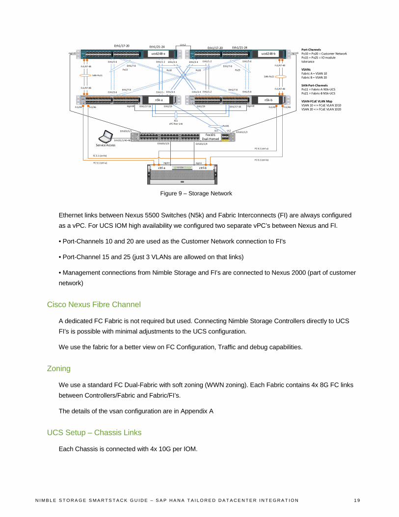
Figure 9 – Storage Network
Ethernet links between Nexus 5500 Switches (N5k) and Fabric Interconnects (FI) are always configured as a vPC. For UCS IOM high availability we configured two separate vPC’s between Nexus and FI.
• Port-Channels 10 and 20 are used as the Customer Network connection to FI's
• Port-Channel 15 and 25 (just 3 VLANs are allowed on that links)
• Management connections from Nimble Storage and FI's are connected to Nexus 2000 (part of customer network)
Cisco Nexus Fibre Channel
A dedicated FC Fabric is not required but used. Connecting Nimble Storage Controllers directly to UCS FI’s is possible with minimal adjustments to the UCS configuration.
We use the fabric for a better view on FC Configuration, Traffic and debug capabilities.
Zoning
We use a standard FC Dual-Fabric with soft zoning (WWN zoning). Each Fabric contains 4x 8G FC links between Controllers/Fabric and Fabric/FI’s.
The details of the vsan configuration are in Appendix A
UCS Setup – Chassis Links
Each Chassis is connected with 4x 10G per IOM.
Eth1/17-20 Eth1/21-24 Eth1/17-20 Eth1/21-24
ucs6248-a ucs6248-b
Eth1/1-2
Eth1/1-2
Eth1/1-2
Eth1/1-2
Eth1/3-4
Eth1/3-4Eth1/3-4
Eth1/3-4
Po10 Po20
n5k-a n5k-b
Eth1/5-6
Eth1/5-6
Eth1/5-6
Eth1/5-6
Po15 Po25
Eth1/7-8
Eth1/7-8
Eth1/7-8
Eth1/7-8
Fc1/47-48
Fc1/47-48
Fc1/47-48
Fc1/47-48
SAN-Po11 SAN-Po21
L1+L2
UL1 UL2
Eth1/19 Eth1/19
Po101
Fex101Dual-Homed
Eth1/17-18 Eth1/17-18
Po1vPC Peer Link
mgmt0 mgmt0
mgmt0 mgmt0
Eth101/1/2Eth101/1/1
Service AccessEth101/1/40-48
Fc1/45 Fc1/46 Fc1/45 Fc1/46
FC 5.1 (ctrl-b)
Eth101/1/3 Eth101/1/4
mgmt mgmt
Port-ChannelsPo10 + Po20 = Customer NetworkPo15 + Po25 = IO module tolerance
VSANsFabric A = VSAN 10Fabric B = VSAN 20
SAN-Port-ChannelsPo11 = Fabric-A N5k-UCSPo21 = Fabric-B N5k-UCS
VSAN-FCoE VLAN MapVSAN 10 <-> FCoE VLAN 1010VSAN 20 <-> FCoE VLAN 1020
ctrl-a ctrl-b FC 5.1 (ctrl-a)
FC 6.1 (ctrl-b)
FC 6.1 (ctrl-a)
N I M B L E S T O R A G E S M A R T S T A C K G U I D E – S A P H A N A T A I L O R E D D A T A C E N T E R I N T E G R A T I O N 1 9

UCS Setup – Power Policy
Power Policy depends on how the blades are configured (hardware) and which settings regarding power saving (CPU C-states and options) are configured. A fully equipped chassis without any configured power saving may requires N+1 for full performance instead of Grid for more availability.
N+1 = three active PSU; one PSU can fail
Grid = two active PSU; two can fail
Depending on the current power usage, it is possible that an N+1 configuration can survive with less than 3 PSU’s but without any warranty.
Figure 10 – Global Policies
UCS Setup – Switching Mode
Both FI’s run in Ethernet and FC End-Host Mode.
Figure 11 – Switching Mode
N I M B L E S T O R A G E S M A R T S T A C K G U I D E – S A P H A N A T A I L O R E D D A T A C E N T E R I N T E G R A T I O N 2 0

UCS Setup – Unified Ports
This port configuration is an example.
Onboard ports 1/1 – 26 are configured as Ethernet. Onboard ports 1/27 – 32 are configured as FC.
Figure 12 – Port Configuration - Ethernet / FC
UCS Setup – VLANs
Not all configured VLANs are required. Only VLANs T01-Client, T01-Storage and T01-Internal are required as a minimal configuration.
The VLAN setup is customer specific.
Figure 13 – VLAN Configuration
VLANs are grouped in VLAN-Groups and assigned to a specific uplink interface.
Figure 14 – Client Zone VLAN
N I M B L E S T O R A G E S M A R T S T A C K G U I D E – S A P H A N A T A I L O R E D D A T A C E N T E R I N T E G R A T I O N 2 1

Figure 15 – Client Zone Port Channel
Figure 16 – Internal Zone VLAN
Figure 17 – Internal Zone Port Channel
UCS Setup – VSANs
Two VSANs are required, one each Fabric. VSANs are mapped to an internal FCoE VLAN.
N I M B L E S T O R A G E S M A R T S T A C K G U I D E – S A P H A N A T A I L O R E D D A T A C E N T E R I N T E G R A T I O N 2 2

Figure 18 – VSAN A
Figure 19 – VSAN B
UCS Setup – Network Control Policy
Figure 20 – Network Control Policy
N I M B L E S T O R A G E S M A R T S T A C K G U I D E – S A P H A N A T A I L O R E D D A T A C E N T E R I N T E G R A T I O N 2 3

UCS Setup – MAC Pools
Create a MAC Pool for each VLAN or a single pool for all VLANs.
Figure 21 – VLAN MAC Pool
Figure 22 – VLAN MAC Pool Blocks
UCS Setup – vNIC Templates
We create a vNIC template for every vNIC we use, e.g. T01-Client, T01-Storage, T01-Internal.
Figure 23 – Client vNIC Template
N I M B L E S T O R A G E S M A R T S T A C K G U I D E – S A P H A N A T A I L O R E D D A T A C E N T E R I N T E G R A T I O N 2 4

Figure 24 – Internal vNIC Template
Figure 25 – Storage vNIC Template
UCS Setup – WWNN Pool
This pool configuration is an example.
N I M B L E S T O R A G E S M A R T S T A C K G U I D E – S A P H A N A T A I L O R E D D A T A C E N T E R I N T E G R A T I O N 2 5

Figure 26 – WWNN Pool
Figure 27 – WWN Pool Blocks
UCS Setup – WWPN Pool Fabric A
This pool configuration is an example.
Figure 28 – VSAN A WWPN Pool
Figure 29 – VSAN A WWN Pool Blocks
UCS Setup – WWPN Pool Fabric B
This pool configuration is an example.
N I M B L E S T O R A G E S M A R T S T A C K G U I D E – S A P H A N A T A I L O R E D D A T A C E N T E R I N T E G R A T I O N 2 6

Figure 30 – VSAN B WWPN Pool
Figure 31 – VSAN B WWN Pool Blocks
UCS Setup – vHBA Templates
This configuration is an example.
Figure 32 – vHBA - Fabric A
N I M B L E S T O R A G E S M A R T S T A C K G U I D E – S A P H A N A T A I L O R E D D A T A C E N T E R I N T E G R A T I O N 2 7

Figure 33 – vHBA - Fabric B
UCS Setup – Ethernet Adapter Policy
These settings are non UCS standards and are documented in the Cisco SAP HANA TDI whitepaper. These settings are necessary to meet the network speed KPIs.
Figure 34 – Ethernet Adapter Settings
N I M B L E S T O R A G E S M A R T S T A C K G U I D E – S A P H A N A T A I L O R E D D A T A C E N T E R I N T E G R A T I O N 2 8

Figure 35 – Ethernet Adapter Options
UCS Setup – BIOS Policy
These settings are documented in the Cisco SAP HANA TDI whitepaper and necessary to meet the KPIs.
Figure 36 – BIOS Policy
N I M B L E S T O R A G E S M A R T S T A C K G U I D E – S A P H A N A T A I L O R E D D A T A C E N T E R I N T E G R A T I O N 2 9

Figure 37 – BIOS Policy – Advanced
N I M B L E S T O R A G E S M A R T S T A C K G U I D E – S A P H A N A T A I L O R E D D A T A C E N T E R I N T E G R A T I O N 3 0

Figure 38 – BIOS Policy – RAS
Figure 39 – BIOS Policy – Serial
Figure 40 – BIOS Policy – Server
UCS Setup – Boot Policy
Note: The CD will be removed later.
N I M B L E S T O R A G E S M A R T S T A C K G U I D E – S A P H A N A T A I L O R E D D A T A C E N T E R I N T E G R A T I O N 3 1

Figure 41 – Boot Policy
Figure 42 – Boot Interface Ordering
UCS Setup – Default Host Firmware Package
This configuration is an example.
N I M B L E S T O R A G E S M A R T S T A C K G U I D E – S A P H A N A T A I L O R E D D A T A C E N T E R I N T E G R A T I O N 3 2

Figure 43 – UCS Host Firmware
UCS Setup – IPMI User
Set a password for user sapadmin.
Figure 44 – IPMI User
UCS Setup – Maintenance Policy
This configuration is an example.
Figure 45 – Maintenance Policy
UCS Setup – Power Control Policy
This configuration is an example.
N I M B L E S T O R A G E S M A R T S T A C K G U I D E – S A P H A N A T A I L O R E D D A T A C E N T E R I N T E G R A T I O N 3 3

Figure 46 – Power Control Policy
UCS Setup – Serial over LAN Policy
This configuration is an example.
Figure 47 – LAN Policy
UCS Setup – UUID Pool
This configuration is an example.
Figure 48 – UUID Pool
N I M B L E S T O R A G E S M A R T S T A C K G U I D E – S A P H A N A T A I L O R E D D A T A C E N T E R I N T E G R A T I O N 3 4

Figure 49 – UUID Pool Blocks
UCS Setup – Service Profile Template
This configuration is an example.
Figure 50 – Service Profile Template
N I M B L E S T O R A G E S M A R T S T A C K G U I D E – S A P H A N A T A I L O R E D D A T A C E N T E R I N T E G R A T I O N 3 5

Figure 51 – Service Profile – Storage
Figure 52 – Service Profile – Create WWNN
N I M B L E S T O R A G E S M A R T S T A C K G U I D E – S A P H A N A T A I L O R E D D A T A C E N T E R I N T E G R A T I O N 3 6
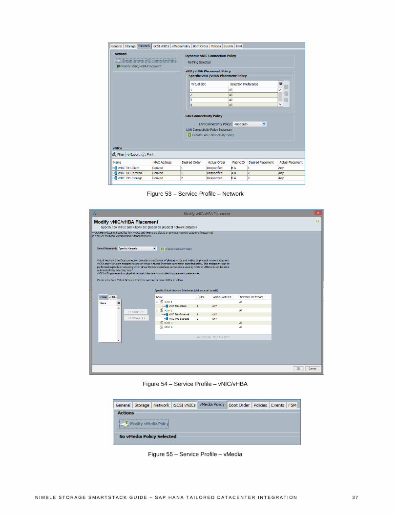
Figure 53 – Service Profile – Network
Figure 54 – Service Profile – vNIC/vHBA
Figure 55 – Service Profile – vMedia
N I M B L E S T O R A G E S M A R T S T A C K G U I D E – S A P H A N A T A I L O R E D D A T A C E N T E R I N T E G R A T I O N 3 7
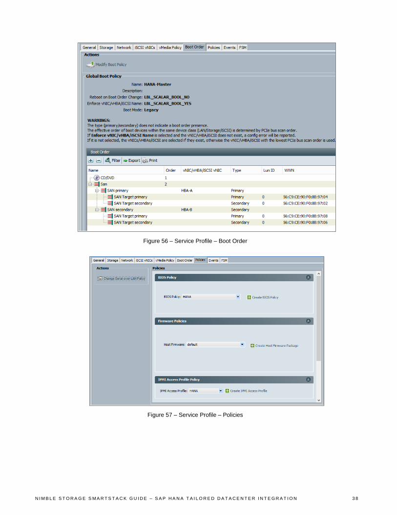
Figure 56 – Service Profile – Boot Order
Figure 57 – Service Profile – Policies
N I M B L E S T O R A G E S M A R T S T A C K G U I D E – S A P H A N A T A I L O R E D D A T A C E N T E R I N T E G R A T I O N 3 8

Figure 58 – Service Profile – Policies (cont)
Figure 59 – SOL Policy
N I M B L E S T O R A G E S M A R T S T A C K G U I D E – S A P H A N A T A I L O R E D D A T A C E N T E R I N T E G R A T I O N 3 9
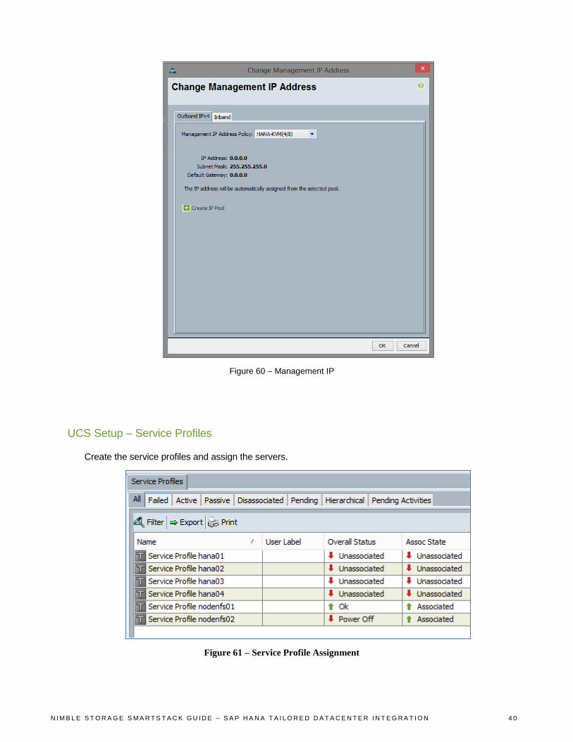
Figure 60 – Management IP
UCS Setup – Service Profiles
Create the service profiles and assign the servers.
Figure 61 – Service Profile Assignment
N I M B L E S T O R A G E S M A R T S T A C K G U I D E – S A P H A N A T A I L O R E D D A T A C E N T E R I N T E G R A T I O N 4 0

Nimble Storage – Storage Setup
The raid configuration is by default a triple-parity configuration. There is no specific configuration to be done. Details can be found can be found in this technology overview http://info.nimblestorage.com/rs/nimblestorage/images/nimblestorage_technology_overview.pdf
Nimble Storage – Network Configuration
This configuration is an example.
Figure 62 – Nimble Management Network Setup
Figure 63 – Management Subnet Assignment
N I M B L E S T O R A G E S M A R T S T A C K G U I D E – S A P H A N A T A I L O R E D D A T A C E N T E R I N T E G R A T I O N 4 1

Figure 64 – Management Port Assignment
Figure 65 – Nimble Support Interfaces
Nimble Storage – Initiator Groups and used WWPNs
This configuration is an example.
Figure 66 – Host Initiator Groups
N I M B L E S T O R A G E S M A R T S T A C K G U I D E – S A P H A N A T A I L O R E D D A T A C E N T E R I N T E G R A T I O N 4 2

Figure 67 – VSAN A – Nimble WWN Initiators
Figure 68 – VSAN B – Nimble WWN Initiators
For Failover, HANA- Data and Log LUNs are exported to all HANA Initiators. This means each HANA Node can access all HANA Data and Log LUNs (required for failover). SAN Zoning must not be adjusted. Example for HANA02 Data LUN:
Figure 69 – Initiator Group – Volume Assignment
Nimble Storage – Volumes
Please follow the SAP HANA installation guide and the Cisco SAP HANA TDI whitepaper for the Volume sizing and layout. For a 4 Node Scale-out with 256 GB RAM it could look like this:
N I M B L E S T O R A G E S M A R T S T A C K G U I D E – S A P H A N A T A I L O R E D D A T A C E N T E R I N T E G R A T I O N 4 3

Figure 70 – Nimble Storage Boot Volumes
OS installation
Please follow the Cisco SAP HANA TDI whitepaper instructions.
NOTE: Please make sure to have the boot LUN during the installation presented to the server only as a single LUN without any redundancy and adjust the zoning later.
When the OS is installed from a plain SLES or RHEL installation media please update the OS to the necessary kernel and patch level required by the SAP HANA revision to be installed.
OS configuration
This OS configuration is provided as an example in Appendix B.
Multipathing /etc/multipath.conf
defaults { user_friendly_names yes } blacklist { devnode "^(ram|raw|loop|fd|md|dm-|sr|scd|st)[0-9]*" devnode "^hd[a-z][[0-9]*]" device { vendor "*" product "*" } } blacklist_exceptions { device { vendor "Nimble" product "Server" } } devices { device { vendor "Nimble" product "Server" no_path_retry 20 rr_weight priorities
N I M B L E S T O R A G E S M A R T S T A C K G U I D E – S A P H A N A T A I L O R E D D A T A C E N T E R I N T E G R A T I O N 4 4

path_grouping_policy group_by_prio rr_min_io 20 failback 10 path_selector "round-robin 0" path_checker "tur" prio "alua" } }
Generate SSH Keys and exchange with all other HANA nodes. This facilitates automation of updates and other management tasks.
Figure 71 – Generate ssh Keys
Multipathing
This configuration shows the four hosts configured for the TDI testing.
N I M B L E S T O R A G E S M A R T S T A C K G U I D E – S A P H A N A T A I L O R E D D A T A C E N T E R I N T E G R A T I O N 4 5
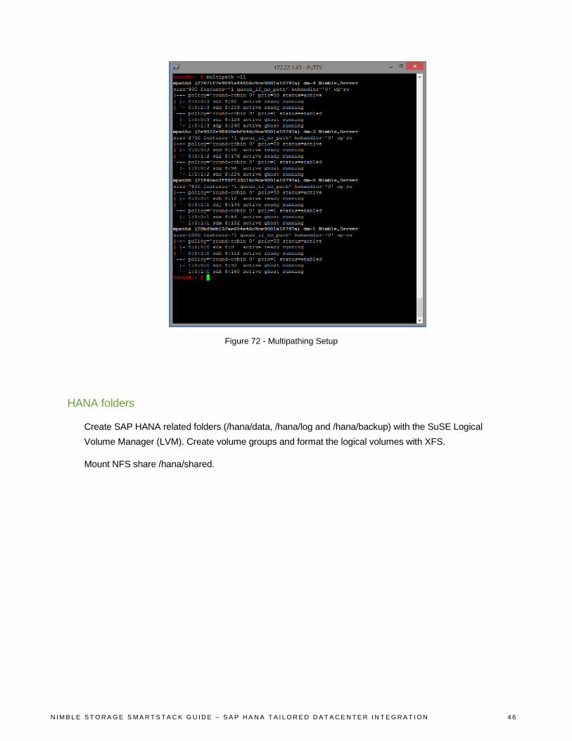
Figure 72 - Multipathing Setup
HANA folders
Create SAP HANA related folders (/hana/data, /hana/log and /hana/backup) with the SuSE Logical Volume Manager (LVM). Create volume groups and format the logical volumes with XFS.
Mount NFS share /hana/shared.
N I M B L E S T O R A G E S M A R T S T A C K G U I D E – S A P H A N A T A I L O R E D D A T A C E N T E R I N T E G R A T I O N 4 6

Figure 73 – Mount NFS Share
Add NFS share to /etc/fstab
Figure 74 – Configure fstab
N I M B L E S T O R A G E S M A R T S T A C K G U I D E – S A P H A N A T A I L O R E D D A T A C E N T E R I N T E G R A T I O N 4 7
Summary This document provides an overview of the SAP HANA Solution on SmartStack. This guide follows best practices from Nimble Storage, Cisco, and SAP for construction of the compute, network and storage elements needed for a TDI tested solution to support SAP HANA.
Using the setup examples provided in this guide and staying with the vendor defined solutions for SmartStack san SAP HANA TDI configurations, you should be able to construct a similar solution specific to your own environment needs.
This solution guide is not intended to cover every possible configuration setup or detail. For more information, contact your local integrator or vendor for more details.
N I M B L E S T O R A G E S M A R T S T A C K G U I D E – S A P H A N A T A I L O R E D D A T A C E N T E R I N T E G R A T I O N 4 8

Appendix A – VSAN Database Configuration vsan database vsan 10 name "Fabric-A" fcdomain fcid database vsan 10 wwn 20:1f:54:7f:ee:87:64:c0 fcid 0xe20000 dynamic vsan 10 wwn 20:20:54:7f:ee:87:64:c0 fcid 0xe20020 dynamic vsan 10 wwn 56:c9:ce:90:f0:8b:97:02 fcid 0xe20040 dynamic vsan 10 wwn 56:c9:ce:90:f0:8b:97:04 fcid 0xe20060 dynamic vsan 10 wwn 20:00:00:25:b5:aa:aa:00 fcid 0xe20001 dynamic vsan 10 wwn 20:00:00:25:b5:aa:aa:01 fcid 0xe20021 dynamic vsan 10 wwn 20:00:00:25:b5:aa:aa:02 fcid 0xe20002 dynamic vsan 10 wwn 20:00:00:25:b5:aa:aa:03 fcid 0xe20022 dynamic vsan 10 wwn 20:00:00:25:b5:aa:aa:04 fcid 0xe20003 dynamic vsan 10 wwn 20:00:00:25:b5:aa:aa:05 fcid 0xe20023 dynamic vsan 10 wwn 20:00:00:25:b5:aa:aa:06 fcid 0xe20004 dynamic vsan 10 wwn 20:00:00:25:b5:aa:aa:07 fcid 0xe20005 dynamic vsan 10 wwn 20:00:00:25:b5:aa:aa:08 fcid 0xe20006 dynamic vsan 10 wwn 20:00:00:25:b5:aa:aa:09 fcid 0xe20007 dynamic vsan 10 wwn 20:00:00:25:b5:aa:aa:0b fcid 0xe20024 dynamic vsan 10 wwn 20:00:00:25:b5:aa:aa:0c fcid 0xe20008 dynamic vsan 10 wwn 20:00:00:25:b5:aa:aa:0d fcid 0xe20025 dynamic vsan 10 wwn 20:00:00:25:b5:aa:aa:0a fcid 0xe20009 dynamic vsan 1 wwn 56:c9:ce:90:f0:8b:97:03 fcid 0x650000 dynamic vsan 1 wwn 56:c9:ce:90:f0:8b:97:01 fcid 0x650020 dynamic […] !Full Zone Database Section for vsan 10 fcalias name Nimble_Controller-A_Port1 vsan 10 member pwwn 56:c9:ce:90:f0:8b:97:04 fcalias name Nimble_Controller-A_Port2 vsan 10 member pwwn 56:c9:ce:90:f0:8b:97:02 fcalias name nodenfs01_hba-a vsan 10 member pwwn 20:00:00:25:b5:aa:aa:00 fcalias name nodenfs02_hba-a vsan 10 member pwwn 20:00:00:25:b5:aa:aa:01 fcalias name hana01_hba-a vsan 10 member pwwn 20:00:00:25:b5:aa:aa:02 fcalias name hana02_hba-a vsan 10 member pwwn 20:00:00:25:b5:aa:aa:03 fcalias name hana03_hba-a vsan 10 member pwwn 20:00:00:25:b5:aa:aa:04 fcalias name hana04_hba-a vsan 10 member pwwn 20:00:00:25:b5:aa:aa:05 fcalias name drx-test_hba-a vsan 10 member pwwn 20:00:00:25:b5:aa:aa:06 fcalias name nodenfs01_hba-c vsan 10 member pwwn 20:00:00:25:b5:aa:aa:07 fcalias name nodenfs02_hba-c vsan 10 member pwwn 20:00:00:25:b5:aa:aa:06 fcalias name esxi01_hba-a vsan 10 member pwwn 20:00:00:25:b5:aa:aa:08 fcalias name esxi02_hba-a vsan 10 member pwwn 20:00:00:25:b5:aa:aa:09 fcalias name Nimble_Controller-A_Port3 vsan 10
N I M B L E S T O R A G E S M A R T S T A C K G U I D E – S A P H A N A T A I L O R E D D A T A C E N T E R I N T E G R A T I O N 4 9

member pwwn 56:c9:ce:90:f0:8b:97:03 fcalias name Nimble_Controller-A_Port4 vsan 10 member pwwn 56:c9:ce:90:f0:8b:97:01 fcalias name hana05_hba-a vsan 10 member pwwn 20:00:00:25:b5:aa:aa:0a fcalias name hana06_hba-a vsan 10 member pwwn 20:00:00:25:b5:aa:aa:0b fcalias name hana07_hba-a vsan 10 member pwwn 20:00:00:25:b5:aa:aa:0c fcalias name hana08_hba-a vsan 10 member pwwn 20:00:00:25:b5:aa:aa:0d zone name z_nodenfs01 vsan 10 member fcalias Nimble_Controller-A_Port1 member fcalias Nimble_Controller-A_Port2 member fcalias nodenfs01_hba-a member fcalias nodenfs01_hba-c zone name z_nodenfs02 vsan 10 member fcalias Nimble_Controller-A_Port1 member fcalias Nimble_Controller-A_Port2 member fcalias nodenfs02_hba-a member fcalias nodenfs02_hba-c zone name z_hana01_hba-a vsan 10 member fcalias Nimble_Controller-A_Port1 member fcalias Nimble_Controller-A_Port2 member fcalias hana01_hba-a member fcalias Nimble_Controller-A_Port3 member fcalias Nimble_Controller-A_Port4 zone name z_hana02_hba-a vsan 10 member fcalias Nimble_Controller-A_Port1 member fcalias Nimble_Controller-A_Port2 member fcalias hana02_hba-a member fcalias Nimble_Controller-A_Port3 member fcalias Nimble_Controller-A_Port4 zone name z_hana03_hba-a vsan 10 member fcalias Nimble_Controller-A_Port1 member fcalias Nimble_Controller-A_Port2 member fcalias hana03_hba-a member fcalias Nimble_Controller-A_Port3 member fcalias Nimble_Controller-A_Port4 zone name z_hana04_hba-a vsan 10 member fcalias Nimble_Controller-A_Port1 member fcalias Nimble_Controller-A_Port2 member fcalias hana04_hba-a member fcalias Nimble_Controller-A_Port3 member fcalias Nimble_Controller-A_Port4 zone name z_drx-test_hba-a vsan 10 member fcalias Nimble_Controller-A_Port1 member fcalias Nimble_Controller-A_Port2 member fcalias drx-test_hba-a zone name esxi01_hba-a vsan 10 member fcalias Nimble_Controller-A_Port1 member fcalias Nimble_Controller-A_Port2 member fcalias esxi01_hba-a zone name esxi02_hba-a vsan 10
N I M B L E S T O R A G E S M A R T S T A C K G U I D E – S A P H A N A T A I L O R E D D A T A C E N T E R I N T E G R A T I O N 5 0

member fcalias Nimble_Controller-A_Port1 member fcalias Nimble_Controller-A_Port2 member fcalias esxi02_hba-a zone name z_hana05_hba-a vsan 10 member fcalias Nimble_Controller-A_Port1 member fcalias Nimble_Controller-A_Port2 member fcalias Nimble_Controller-A_Port3 member fcalias Nimble_Controller-A_Port4 member fcalias hana05_hba-a zone name z_hana06_hba-a vsan 10 member fcalias Nimble_Controller-A_Port1 member fcalias Nimble_Controller-A_Port2 member fcalias Nimble_Controller-A_Port3 member fcalias Nimble_Controller-A_Port4 member fcalias hana06_hba-a zone name z_hana07_hba-a vsan 10 member fcalias Nimble_Controller-A_Port1 member fcalias Nimble_Controller-A_Port2 member fcalias Nimble_Controller-A_Port3 member fcalias Nimble_Controller-A_Port4 member fcalias hana07_hba-a zone name z_hana08_hba-a vsan 10 member fcalias Nimble_Controller-A_Port1 member fcalias Nimble_Controller-A_Port2 member fcalias Nimble_Controller-A_Port3 member fcalias Nimble_Controller-A_Port4 member fcalias hana08_hba-a zoneset name zSet_Fabric-A vsan 10 member z_nodenfs01 member z_nodenfs02 member z_hana01_hba-a member z_hana02_hba-a member z_hana03_hba-a member z_hana04_hba-a member z_drx-test_hba-a member esxi01_hba-a member esxi02_hba-a member z_hana05_hba-a member z_hana06_hba-a member z_hana07_hba-a member z_hana08_hba-a zoneset activate name zSet_Fabric-A vsan 10
N I M B L E S T O R A G E S M A R T S T A C K G U I D E – S A P H A N A T A I L O R E D D A T A C E N T E R I N T E G R A T I O N 5 1

Appendix B – OS Configuration Network configuration for Node hana04 (example) in /etc/sysconfig/network/ifcfg-ethx:
Client Network (eth0):
BOOTPROTO='static' BROADCAST='172.22.1.255' ETHTOOL_OPTIONS='' IPADDR='172.22.1.43' MTU='1500' NAME='VIC Ethernet NIC' NETWORK='172.22.1.0' REMOTE_IPADDR='' STARTMODE='auto' USERCONTROL='no' NETMASK='255.255.255.0'
Storage Network (eth1):
BOOTPROTO='static' BROADCAST='172.22.220.255' ETHTOOL_OPTIONS='' IPADDR='172.22.220.43' MTU='9000' NAME='VIC Ethernet NIC' NETWORK='172.22.220.0' REMOTE_IPADDR='' STARTMODE='auto' USERCONTROL='no' NETMASK='255.255.255.0'
Internal Network (eth2):
BOOTPROTO='static' BROADCAST='172.22.110.255' ETHTOOL_OPTIONS='' IPADDR='172.22.110.43' MTU='9000' NAME='VIC Ethernet NIC' NETWORK='172.22.110.0' REMOTE_IPADDR='' STARTMODE='auto' USERCONTROL='no' NETMASK='255.255.255.0'
Default Gateway in /etc/sysconfig/network/routes
default 172.22.1.1 - -
Set Hostname in /etc/HOSTNAME
hana04
/etc/hosts content (distributed to all hana nodes):
N I M B L E S T O R A G E S M A R T S T A C K G U I D E – S A P H A N A T A I L O R E D D A T A C E N T E R I N T E G R A T I O N 5 2

127.0.0.1 localhost 172.22.1.40 hana01 172.22.1.41 hana02 172.22.1.42 hana03 172.22.1.43 hana04 172.22.1.30 nodenfs01 172.22.1.31 nodenfs02 172.22.1.10 ucs6248 172.22.1.15 nimble-storage 172.22.1.2 n5k-a 172.22.1.3 n5k-b 172.22.110.20 nodenfs-st 172.22.110.30 nodenfs01-st 172.22.110.31 nodenfs02-st 172.22.110.40 hana01-st 172.22.110.41 hana02-st 172.22.110.42 hana03-st 172.22.110.43 hana04-st 172.22.220.40 hana01-int 172.22.220.41 hana02-int 172.22.220.42 hana03-int 172.22.220.43 hana04-int 192.53.103.108 ptbtime1.ptb.de # special IPv6 addresses ::1 host ipv6host ipv6-loopback fe00::0 ipv6net ff00::0 ipv6-mcastprefix ff02::1 ipv6-allnodes ff02::2 ipv6-allrouters ff02::3 ipv6-allhosts
N I M B L E S T O R A G E S M A R T S T A C K G U I D E – S A P H A N A T A I L O R E D D A T A C E N T E R I N T E G R A T I O N 5 3

Nimble Storage, Inc. 211 River Oaks Parkway, San Jose, CA 95134 Tel: 877-364-6253; 408-432-9600 | www. nimblestorage. com | info@nimblestorage. com © 2015 Nimble Storage, Inc. . Nimble Storage, InfoSight, CASL, SmartStack, and NimbleConnect are trademarks or registered trademarks of Nimble Storage, Inc. All other trademarks are the property of their respective owners. STSK-HANA-0415
N I M B L E S T O R A G E S M A R T S T A C K G U I D E – S A P H A N A T A I L O R E D D A T A C E N T E R I N T E G R A T I O N 5 4