(reference book for my4130) - clock.5u.tripod.comclock.5u.tripod.com/cgi-bin/metal_casting.pdf ·...
TRANSCRIPT

-3
METAL CASTING
(Reference Book for MY4130)
By Prof. Karl B. Rundman
Dept. of Materials Science and EngineeringMichigan Tech. University
QUICKESTLEAST EXPENSIVEROUTETO A NEAR NET SHAPE PRODUCT
METAL CASTING

-2
TABLE OF CONTENTS
Page1. I. INTRODUCTION1. Metal Castings, Metal Casting Process3. Metal Casting Design6. Pattern Design7. Rapid Prototyping10. II. SAND CASTING PROCESSES11. Sand Size Distribution11. Strength of Green Sand14. Permeability and Compactibility16. Temperature Dependence of Green Strength19. Chemically Bonded Molding and Core Sand22. Reclamation of Foundry Sand23. Sand Life Cycle24. Reclamation Systems26. III. OTHER CASTING PROCESSES26. Precision Casting; Cosworth Process27. Rheocasting & Thixocasting28. Lost Foam Casting30. Die Casting31. Squeeze Casting32. Investment Casting33. IV. MELTING OF METALS AND ALLOYS33. Energy and Material flow in Cupola Melting33. Cold Blast Cupola35. Heat of Combustion and Iron/Coke Ratio in Charge36. Energy of Melting and Energy Balance in Cupola39. V. FLUID FLOW AND GATING DESIGN39. Laws of Mass and Energy Conservation (Bernoulli’s Law)40. Velocity at Efflux Point (Mold Filling Time)41. Pressure at Intermediate Point in Gating System (Gas Aspiration)43. Number of Gates in System44. Fluidity of Molten Metals45. VI. SOLIDIFICATION AND PROCESSING OF METAL CASTINGS45. Intrinsic and Extrinsic Factors46. Microscale-Dendritic Solidification46. Solidification on a Macroscale - Defect Production47. Controlled Thermal or Mechanical Treatment after Casting47. Latent Heat of Solidification, Cooling Curves48. Steady State Heat Transfer Processes - Fick’s First Law49. VII. HEAT TRANSFER AND SOLIDIFICATION IN INSULATING MOLDS53. VIII. SHRINKAGE, RISER DESIGN 53. Shrinkage in Metals During Solidification

-1
55. Macroshrinkage 55. Microshrinkage56. Riser Design57. Calculation of Modulus of Riser and Casting58. Location of Riser, Size and Shape of Riser60. Number of Risers61. Casting Yield62. IX. HEAT TRANSFER AND SOLIDIFICATION IN PERMANENT MOLDS63. Finite Element Analysis of Solidification - Die Casting69. X. CONTINUOUS AND SEMI-CONTINUOUS CASTING69. Continuous Casting of Steel71. Semi-Continuous Casting of Al Alloys, Free Machining Brass72. Microstructure of Continuous and Semi-Continuous Castings73. XI. SOLIDIFICATION, BINARY SYSTEM73. Equilibrium Solidification73. Non-equilibrium Solidification74. The Scheil Equation and Coring in Dendrites76. XII. ALUMINUM ALLOYS77. Aluminum Casting Alloys Processing 77. Processing and Microstructure of Several Selected Al Si Base Alloys77. Alloy 356.2, Modification & Age Hardening79. Alloy 319.1, Grain Refinement with TiB80. Alloy KS281, Phosphorous as a Nucleation Agent for Proeutectic b.81. XIII. ADDITIVES TO MOLTEN METAL83. XIV. CAST IRON84. Phase Equilibria in Fe - C- Si System, Stable and Metastable Diagrams85. Gray Cast Iron, Section Size Effects and Inoculation, Chill Wedges91. Mechanical Properties of Gray Cast Iron95. Ductile Cast Iron, Production101. Microstructures of Hypereutectic Ductile Cast Irons103. Alloying of Cast Irons104. Mechanical Properties of Ductile Cast Irons106. Austempered Ductile Cast Iron110. Compacted Graphite Iron and Malleable Cast Iron114 XV. DEFECTS IN CASTINGS114. Gases in Metals115. Hot Tears117. Residual Stresses in Castings120. Residual Stress Measurements122. XVI. CAST STEEL122. Peritectic Reaction, Segregation of Alloy Elements During Solidification123. Segregation of Alloying Elements During Solidification of Steel125. Melting and Refining Steel126. Mechanical Properties of Cast Steel128. Weldability of Cast Irons and Steels130. Selective Surface Hardening of Cast Steels and Irons

0
131. XVII. CAST COPPER ALLOYS131. Brasses, Bronzes and Precipitation Hardening134. XVIII. HOMOGENIZATION OF CASTINGS139. XIX. ENVIRONMENTAL CONCERNS IN METAL CASTING140. Product Life Cycle and the Environmental Concern Envelope148. RCRA, Lead Flow in Foundries

1
I. IntroductionMetal Castings
Metal castings form integral components of devices that perform useful functions for human beings, an idea shown schematically below:
The cast component has a shape, size, chemical composition and metallurgical microstructure which is determined by engineering decisions arrived at by:
A. Design Engineers (Mechanical Engineers)B. Pattern Makers (Skilled craftsman, CAD)C. Casting Engineers ( Metallurgical Engineers)D. Manufacturing Engineers (Mechanical, Metallurgical Engineers)
The engineering professionals that carry out this process work together, sharing information so that the casting will perform as intended in a timely and cost effective manner. It should be noted that the casting may only be a small part of the useful device (usually in more sophisticated devices like an automobile where there may be hundreds of components), or it may be the entire device (simple device like a frying pan).Metal Casting Process
The metal casting process is the simplest, most direct route to a near net shape product, and often the least expensive. This process in its fundamental form requires a mold cavity of the desired shape and molten metal to pour into the mold cavity. Humans beings have been producing castings for thousands of years, most often pouring molten metal into molds made of sand. This is schematically shown below, a figure defining the basic components of a mold cavity (cope, drag, parting line, riser, sprue, pouring basin, etc.), as well as that part of the molten metal handling sys-tem known as a ladle. The production of molten metal and molds to make castings has tradition-ally been an art form, an expression of human creativity carried out both for aesthetic and practical reasons. The objective of metal casting has been to produce useful implements for human consumption as well as beautiful works of art. It is clear on examination of ancient art castings as well as modern industrial castings that their production requires significant skill as well as technological know how. The ancient artisan used traditions and learned skills passed down through the ages, as well as experience to produce acceptable castings. The modern pro-
Casting
DEVICEUSEFULFUNCTION
ENERGY
MATERIALS
DesignEngineer
Pattern Maker
CastingEngineer
ManufacturingEngineer
I N F O R M A T I O N

2
ducer of industrial castings makes use of these same skills, but supplements them with an under-standing of the fundamental principles of fluid flow, heat transfer, thermodynamics and metallurgical microstructural development.
These latter engineering skills are used to help design a system which will allow the metal caster to produce a sound (pore free) casting, free from defects (sand inclusions, slag, cracks, etc.), with the correct dimensions and combination of mechanical properties to satisfy the designer’s require-ments for the intended application.
Producing a “good” casting requires a design effort to:1. Create a gating system (pouring basin, sprue, runner) to bring molten metal into the mold cavity free from entrapped slag, sand or gases.2. Provide a riser which feeds liquid metal into the casting cavity as the liquid is cooling and solidifying (all liquid metals will shrink as they cool and most liquid metals will shrink as they solidify). The riser may have to provide up to 5 - 7% by volume for the casting as it solidifies.3. Control heat flow, Q in the above figure, out of the casting so that the last liquid to solidify is in the riser.4. Control the rate of heat flow so as to control the nature of the solidified product.
Modern industrial castings are produced by a wide variety of processes, processes which are broadly defined in terms of: I. The type of mold material (sand, permanent, etc.); II. The man-ner in which the molten metal is introduced into the cavity (gravity, pressure, vacuum); III. The state of the metal (percent which is liquid); IV. The state of the mold cavity itself (air, vacuum, solid, gas).
There are many examples of processes incorporating different combinations of the above which are illustrated in Table 1 below. Each process illustrated in this table can have many differ-ent variations within each category. For example sand casting can involve molds bonded with clay and water (so-called green sand mold) or the sand grains can be bonded with a chemical resin of some type(so-called chemically bonded sand); die casting can be high pressure, low pressure, etc.
�������������������������������������������������������������������������������������������������������������������������������������������������
������������������������������������������������������������
������������������������������������������������������������������������������������������
LADLE
MOLTEN METAL
COPE (Upper half of sand mold)
DRAG
CASTING CAVITY
RISERCORE
PARTING LINE
(Lower half of sand mold)
POURINGBASIN
SPRUE
RUNNER
Q
Q
Q
Q

3
In addition, combinations of two different processes can be present in a given process, i.e. it is common to utilize semi-permanent molds in some processes, where the molds contain both metal and sand components. The combination selected for a given application depends upon the avail-ability of processes, limited only by the creativity and engineering capability of the metal caster.
Metal Casting DesignThe principles of successful casting design involve a systematic blend of experience and
engineering basics to allow the creation of a successful casting, from inception through produc-tion. The major components of the design process are outlined in the six steps listed below and described graphically and schematically in the figure shown.Casting Design Steps
1. Physical Design of Part to be Cast
Table 1: Casting Processes, Mold and Metal Details
Casting Processes
I. Mold Material
II.Manner of Entry
III. State of Metal
IV. State of Mold
Cavity
Sand Casting Sand( Bonded with clay and water or chemi-cals)
Gravity 100% Liquid Air
Permanent Mold Metal Gravity 100% Liquid Air
Die Casting Metal Pressure 100% Liquid Air
Investment Ceramic Gravity 100% Liquid Air, Vacuum, Gas
Lost FoamEPC
Sand(Unbonded)
Gravity 100% Liquid Styrofoam, PMMA
ThixocastingRheocasting
Metal Pressure >50% LiquidBalance Solid
Air
Cosworth Sand Vacuum 100% Liquid Air
V Process Sand(Unbonded with Vacuum and Enclosing Plastic Film)
Gravity 100% Liquid Air
Centrifugal Metal, Graphite Centrifugal Forces
100% Liquid Air, Gas Shroud
Ingot - NOT Cast to Shape
Metal or electro-magnetic Field
Gravity 100% Liquid Air or Gas Shroud
4
Purpose of Casting (Size, Shape), Tolerances (manufacturing and engineering), Dimensional change in processes, Relationship of this Part to Others to Optimize its Design (Concurrent Engineering)
2. Material Selection for Part to be CastMechanical and physical properties, castability, section size sensitivity, fluid flow properties
3. Pattern Production For Molds and CoresGating and Riser Design, Fluid flow and Heat Transfer
4. Casting Process Selection, Casting ProductionLimitations due to metal cast, casting size, dimensional requirementsCost to Produce
5. After Casting ProcessingMachining, heat treating, welding
6. Evaluation of Cast Product
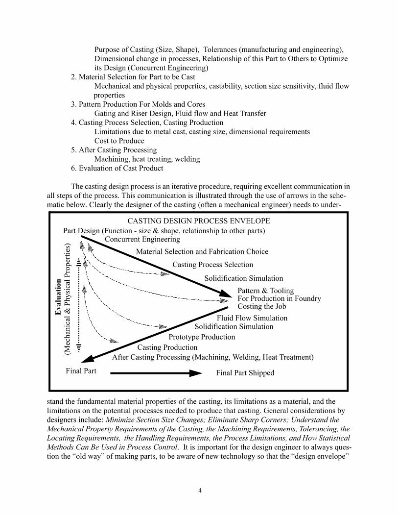
The casting design process is an iterative procedure, requiring excellent communication in all steps of the process. This communication is illustrated through the use of arrows in the sche-matic below. Clearly the designer of the casting (often a mechanical engineer) needs to under-
stand the fundamental material properties of the casting, its limitations as a material, and the limitations on the potential processes needed to produce that casting. General considerations by designers include: Minimize Section Size Changes; Eliminate Sharp Corners; Understand the Mechanical Property Requirements of the Casting, the Machining Requirements, Tolerancing, the Locating Requirements, the Handling Requirements, the Process Limitations, and How Statistical Methods Can Be Used in Process Control. It is important for the design engineer to always ques-tion the “old way” of making parts, to be aware of new technology so that the “design envelope”
Part Design (Function - size & shape, relationship to other parts)
Pattern & Tooling
Material Selection and Fabrication Choice
Casting Process Selection
After Casting Processing (Machining, Welding, Heat Treatment)Casting Production
Final Part
�����������������������
�����������������������������
������������������������������������������������������������������������������������������������������������������������������������������������������������������������������������������������������������������������������������������������������������������������������������������������������������������������������������������������������������������������
��������������������������������������������������������������������������������������������������������������
����
�����������������������
����������������������
��
��������������������������
�����������������������
���������������������������������
������������������������������������������������������������������������������������������������������������������������������������������������������������������������
����������
�����������������������
���������������������������������
����������������������������������������������������������������������������������������������������������������������������������������������������������������������������������������������������������������������������������������������������������
������������������������������������������������������������
��
�����������������������
���������������������
������������������������������������������������������������������������������������������������������������������������������
������
Final Part Shipped
CASTING DESIGN PROCESS ENVELOPE
For Production in Foundry
Eva
luat
ion
(Mec
hani
cal &
Phy
sica
l Pro
perti
es)
Costing the Job
Concurrent Engineering
Prototype Production
Solidification Simulation
Solidification SimulationFluid Flow Simulation

5
can be stretched to its ultimate. Once the material to be cast has been selected and the casting pro-cess chosen, the designer will send drawings (CAD) to the foundry to answer the question, “Can this part be produced in a cost effective way as a casting?” Experienced pattern makers with the help of fluid flow and heat transfer experts (often metallurgical engineers) will proceed to lay out the requirements for the molds and the cores necessary to produce the part. At this point in the process, or even in the design stage, simulation of the solidification of the proposed part is a desirable activity. Modern computers are currently being used with powerful software packages to give a preview of solidification, illustrating in color and in real time the path of solidification in the casting. This methodology is important in reducing the time between design and prototype castings, in providing valuable insight to the designer and the person who does the gating and risering. Clearly a dialogue is needed between the pattern maker, the casting engineer, and the designer to produce tooling to make acceptable castings. This dialogue is illustrated as dashed lines on the above schematic. After the designer and pattern maker are sat-isfied that a viable casting is possible (a process enhanced by the ability of the participants to talk in the same computer language, and for each to have a working knowledge of the other’s prob-lems), the foundry planning people will provide a cost estimate for the designer. Assuming that the cost estimate is within the realm of reality, patterns are produced for prototype castings. (If the cost is too high it will be necessary to return to the drawing board and ask more hard ques-tions.) General considerations applied to the prototype castings by the casting engineer include: Evaluate Dimensional Accuracy; Quantify Microstructural Integrity (presence of required microconstituents, casting defects, porosity, shrinkage, other); Understand Response to Machin-ing, Heat Treatment or Welding; Determine Mechanical Properties in Critical Sections. Rapid protoyping of castings is currently being used to reduce the time between design and cast parts. Stereolithography, Selective Laser Sintering, Fused Deposition Modeling, Laminated Object Manufacturing, Solid Ground Curing, and Direct Shell Production Casting are some of the methods used to produce patterns very quickly from the CAD models of the designer. These methods are described in a following section of this set of notes. It is also crucial that the casting engineer learn that dimensional tolerances are important and that he/she understand the source of the dimensional changes resulting from the casting process as well as the basic dif-ferences in achievable tolerances attained by different casting processes (i.e. lost foam vs green sand vs investment,etc.). Improvements in design can be suggested at this stage of the process as illustrated in the above schematic, improvements which produce a better casting while at the same time minimizing and reducing the cost and difficulty of production. Time Required to Complete the Design Process
The time required to take a casting from the design stage through to satisfactory produc-tion will obviously depend upon many factors, but times ranging from 18 months (e.g., a new part produced by conventional processes or a minor change in an existing casting) to 5 years (e.g., a new part or combination of parts produced by a new process) is not uncommon. Clearly it is to everyone’s advantage to minimize this time, an effort aided by good communication between the various players in the drama, and in these times, wise use of solidification and fluid flow simula-tion, and rapid prototyping techniques. Two examples contrasting a new design with a redesign are given below.
EXAMPLE: New Engine Design - Kohler - TH1416 Overhead Cam Engine (14 - 16 hp)
Old Engine - Sand Castings (Green Sand); 7 Castings in Upper Half (2 cylinder Heads, 2 Cylinders, Upper Half of Block, Intake Manifold, Cam Housing), 4 in

6
Lower Half (Lower Half of Block - Crank Housing, Stud Mounting Bosses, Oil Pump and Filter, Starter Housing). 319 Aluminum alloy (See section on kAl alloy castings for microstructure description)
This engine had been produced for a number of years as 11 different sand cast-ings and assembled to make a satisfactory engine.The need to reduce cost and still improve the product led the design team to consider new ways to produce castings. Enter the LOST FOAM process. New Engine - Replace the seven castings in the old design with one Lost Foam Casting. Replace the four castings in the old design with one Lost Foam Casting. In this process, 7 foam patterns are glued together to make one pattern for casting the upper half, and 4 foam patterns are glued together to make the lower half. These assemblies together with a sprue (the entry point for molten metal) then have sand compacted and vibrated around them prior to pouring the casting. This change from 11 separate castings to 2 castings eliminates many manufacturing steps, from machining to assembly. All of the gaskets and seals previously needed are eliminated. In this process even the oil passages are cast-in thereby eliminating the need to drill holes. 319 Aluminum alloy
Time Line - There is a significant learning curve for the design team and the foundry which is producing the castings. This new design has been in process for about 3.5 years. Prototype castings have been produced and are being tested.
EXAMPLE: Redesign of the Existing Head for a 3500 Series Caterpillar Engine, so that the engine would run cooler. Gray Cast Iron (See sections in these notes on gray iron describing the microstructure and properties)The designer came to the pattern shop with new ideas requiring larger water pas-sages so that the engine would run cooler (Late 1994). Modifications of the pattern were made and prototype castings have been produced, with a very large reduction in the temperature at which the engine would run. It is expected that the new heads will be in production by late 1996.In this example the basic casting and the casting process remained the same, gray iron poured into green sand with suitable coring; thus a more rapid turn around time than the example of the change in casting process from green sand to lost foam.
Pattern DesignPattern making is a time - honored skill which is an integral part of the casting process.
Patterns are routinely produced from wood, plastics, and metals depending upon the complexity of the casting being produced, on the number of castings required and obviously on the capability of the pattern shop that is involved. The design of patterns must include the following compo-nents:
1. An allowance for the solid state shrinkage that will always accompany the casting as it cools from the melting temperature to room temperature. This will depend upon the metal being cast, each of which will have its own unique coefficient of thermal expansion, α. For

7
example, α for aluminum at 20 oC is 23.9 x 10⁻⁶ in/inoC, for iron is 11.7 x 10⁻⁶ in/inoC and that for copper is 16.5 x 10⁻⁶ in/in oC (see page 50 - 51). Thus the linear dimensions of the pattern will always be larger than the casting by an amount determined by the linear expansion coefficient. Of course the expansion coefficients for each of the above materials will change somewhat with tem-perature and so the pattern maker will usually give a generous allowance to cover the temperature dependence of the expansion coefficient.
2. Inclusion of a draft angle so that the pattern can be removed from the mold (or in the case of die casting or permanent mold casting, so the casting can be removed from the metal die) after the molding sand has been rammed around the pattern. These draft angles can vary from one casting to another but angles in the range 1 - 2 degrees are quite common.
3. Inclusion of enough extra stock to allow for variations in casting dimensions due to mold preparation, pattern wear, etc. This amount will depend greatly upon the casting process being employed. For example the amount of “extra” stock will be typically greater for a sand cast-ing than for a die casting. Machining and process tolerances are typically greater for sand castings than for permanent mold castings.
Details on pattern making can be found in several publications form the American Foundry Society (AFS).
Rapid Prototyping (Based on Dean Peters’ article in Foundry Management and Technology, June 1996) Rapid prototyping is a technology that allows the building of 3-D models (patterns or
molds) by producing additive layer-by-layer CAT scan type slices of a pattern in plastics, waxes, or paper , or of CAT scan type slices of a mold in ceramics. “Perhaps no other technology since the invention of interchangeable parts and automated assembly lines has held as much promise for the compression of lead times for newly designed parts.”
Some methods of accomplishing such useful work are described below:
StereolithographyStereolithography is the process by which three dimensional plastic objects are
created directly from CAD data. A. Data received from a CAD file is “sliced” into thin, horizontal cross sections.B. Next, an ultraviolet, software-guided laser (HeCd), draws the first cross-section of the
CAD design on the surface of a vat of ultraviolet sensitive photopolymer,or liquid plastic. Where the laser light touches the liquid photopolymer, it solidifies to the pre-cise dimensions of the cross section.
C. When the first layer is completed, an elevator within the system lowers the first solid plastic layer so the next layer can be applied, recoating the the solid layer with liquid photopolymer in preparation for the drawing of the next cross-section.
D. The thickness of each layer ranges from 0.003 - 0.015 in.E. The process continues until the entire CAD file has been transformed into a solid
model, prototype, or casting pattern.F. It is then removed from the vat and begins a brief final curing process after which it can

8
be sanded, plated, or painted.
Laminated Object ManufacturingLaminated object manufacturing is a process by which three dimensional paper
parts are produced by laser cutting of heat sensitive paper. A. A single beam laser cuts the outline of a part “slice” from a CAD file on a sheet of heat
sensitive paper.B. Once the cross sectional outline is completed, another sheet of paper is layered on top
of the first, and the configuration of the next slice is traced by the laser. Application of heat then bonds the second slice to the first, thereby producing the laminates.
C. This cutting and laminating process is continued until the entire part is modeled.D. A prototype results with the approximate consistency of wood.
After Foundry, Sept 97
����������������������������������������������������������������������������������������������������������������
������������������������������������������������������������������������������������������������������������������������������������������������������������������������������������������������������������������������������������������������������������������������������������������������������������������������
������������������������������������������������������������������������������
Resin
LaserScanning Mirror
Cured Resin(Model)
Support Lattice
Platform Lowers as Part is Built
BuildPlatform
After Foundry, Sept 97
���������������������������������������������������������������������������������������������������������
���������������������������������������������������������������������������������������������������������
������������������������������������������������������������
������������������������������������������������������������������
����������������������������������������������������������������������������������������������������������������������������������������������������������������
Paper Supply Roll
Take-up Roll
LaserOptics
X-Y Positioning Device
Built-Up Part Block
Platform���������������������������������������������������������
Example Layer Outline and Crossshatck
Paper

9
Selective Laser SinteringSelective laser sintering is a process by which three dimensional plastic objects
are created directly from a CAD file.A. Data is received from a CAD file.B. A thin layer of heat-fusible powder (such as polystyrene, polycarbonate, polyamide) is
deposited on the working platform of a sinterstation machine.C. The first cross section of the object is then traced out on the powder layer by a heat-
generating CO2 laser. The temperature of the powder impacted by the laser beam is raised to the point of sintering, fusing the powder and particles and forming a solid mass.
D. Another layer of powder is then deposited on top of the first, and the process is repeated until the finished prototype is complete.
Fused Deposition ModelingFused deposition modeling is a process by which three dimensional thermoplastic
objects are built by depositing thermoplastic material in thin layers.A. Solid or surface data from a CAD file is mathematically sliced into horizontal layers.B. A temperature controlled head, driven by the CAD slices, extrudes a thermoplastic
material (ABS, wax, polyamide) one layer at a time. The thermoplastic modeling medium is a 0.070 in. diameter filament that feeds into the temperature-controlled machine head, where it is heated to a semi-liquid state.
C. The head extrudes and precisely deposits the material in thin layers onto a fixtureless base.The head is controlled by toolpath data that are downloaded to the FDM system, which operates on X, Y, and Z axes.
D. As the material solidifies it fuses to the previously deposited layer.
Solid Ground CuringSolid ground curing is a process by which photo-polymer resins are used to build
up a 3D part.A. The process starts with a Unix-based cross section generation of CAD file data.B. An image of the first cross section is produced on an electrostatically charged erasable
glass plate, forming a photo mask.C. A layer of photo-polymer resin is then spread on a flat work platform. D. An ultraviolet light projected through the photo mask solidifies the resin.E. The excess resin is then vacuumed away, and the solidified resin is surrounded by wax.F. The entire layer is then milled to a uniform thickness.G. This process (about 70 seconds per layer) is repeated until all cross sections are com-
pleted.H. The wax is then melted off to yield the completed prototype model.
Direct Shell Production CastingDSPC is a process in which a ceramic mold is produced by a layering process,
thereby eliminating the need for a pattern.A. A mold is generated in a CAD file.

10
B. A ceramic mold is built up by feeding ceramic powder to the CAD-generated slice in the shape of the mold cross section.
C. The ceramic is followed closely by an ink jet printhead which deposits a liquid binder according to the part’s cross section.
D. This is followed by another layer of ceramic and binder until the entire mold has been constructed.
E. Once the mold is finished it can be poured with molten metal yielding the prototype casting directly.
II. Sand Casting ProcessesMolding sands account for the production of the major quantity of castings. Sand is used in
the ratio of as much as 10 tons of sand per ton of metal to as little as 1/4 ton of sand per ton of metal depending upon the type and size of casting and the molding method employed. The major-ity of castings are made in green sand molds, molds whose major components are sand (usually silica, SiO2), clay such as bentonite, and water. The clay - water combination is responsible for the binding action between the sand grains, and can be present in various amounts from 5 to 50 percent by weight. A typical green sand might contain 6 % clay and 3 % water, materials which are replenished as the molding sand is reconstituted and reused again and again. In the ideal world, the sand grains would be reused forever. In actual fact the sand grains themselves suffer some attrition due to mechanical, thermal, and chemical attack in the course of their use and so must be replaced on a consistent basis, usually through the production of cores. This “flow”of sand in a green sand foundry is illustrated below together with the flow of metal.
Clearly in a foundry which is at steady state (produces the same weight castings day in and day out) the amount of new sand added in cores must equal the spent sand and dust lost due to attrition or for other reasons. In fact in most foundries, perfectly good sand is landfilled every day so as to balance the flow of material into and out of a facility. In Michigan in 1991, approximately 1,000,000 tons of sand was landfilled to produce about 1,000,000 tons of cast product. A little reflection by the reader will bring the realization that what comes into a volume (the Plant) must also leave, otherwise it is likely to get very crowded in a hurry (the law of continuity on a large scale).
Clay
Water
Molding SandPreparation Mold Production
Cores (New Sand)
Casting
Molten Metal
Used Sand Molds
Casting
Operation Returns
Solid Metal
Spent SandDust
SAND AND MET AL FLOW

11
While silica is the molding media which is used in largest quantity, other sands are also uti-lized in the foundry for special applicatons, including chromite, olivine, garnet, carbon sands (petro-leum cokes) and other refractory materials that can be obtained with a reasonable cost. Additives commonly used in molding sands includes cereal (finely ground corn flour) and wood flour (cob flour, cereal hulls) for improved flowability of sand and collapsibility after casting, sea coal (a finely ground coal) for improved surface finish, and many other materials which find use in special applica-tions. Details on sand, additives, and testing of sands can be found in Principles of Metal Casting by Heine, Loper, and Rosenthal (1967), chapters 5 and 6, and in the AFS Sand and Core Testing Hand-book.
Sand Size Distribution The properties of molding sand depend strongly upon the size distribution of the sand that is
used, whether it is silica, olivine, chromite, or other aggregate. A typical sand that could be used in a green sand foundry producing cast iron would have a sand size distribution which would be described by most of the sand residing in a size range which would be observed on four or five screens of a standard sieve size distribution. A typical distribution might look like the following:
Details on desirable sand size distributions for specific casting situations and details on measurement of the size distributions can be found in the AFS literature.The Strength of Green Sand
The strength of green sand is invariably determined with the aid of what is called a “standard rammed sample”, that cylindrical sample (when rammed 3 times in an AFS approved ramming device) which has dimensions of 2 inches in diameter by 2inches high. The strength of green sands depends upon a number of factors, including the clay and water content, the type of clay, the sand size distribution, the temperature of the sand, the amount and type of additive, the degree of mulling or mixing, the extent of compaction (number of rams of a testing machine), the adsorbed species (Na or Ca) etc. The data below indicates the effect of moisture for a four screen sand bonded with 7% western bentonite (montmorillonite clay with adsorbed Na+) and 7% southern bentonite (montmoril-
0
5
10
15
20
25
30
10 100 1000AFS Mesh Size
Silica Sand

12
lonite clay with adsorbed Ca++). The data points represent actual measured data in the MY 4130 laboratory. It can be seen that the green compressive strength goes through an apparent maximum at about 3 wt % moisture.
Shear strength measurements are also used as an indicator of a green sand’s strength, where the 2” x 2” standard sample is sheared along the axis of the cylinder. Typically shear strength data is about one fourth that of compression results. This can be seen in the following laboratory data in which both green compression and green shear are plotted vs the number of rams:
5
10
15
20
25
30
35
40
1 2 3 4 5 6 7Weight Percent Moisture
"Four Screen Silica Sand"7 % Western Bentonite7 % Southern Bentonite
�
����������������������������������������������������������������������������������������������������������������������������������������������������������������������������������������������������������������������������������������������������������������������������������������������������������������������������������������������������������������������������������������������������������������
���������������������������������������������������������������������������������������������������������������������������������������������������������������������������������������������������������������������������������������
����������������������������������������������������������������������������������������������������������������������������������������������������������������������������������������������������������������������������������������������������������������������������������� ���������

13
Perhaps the most sensitive strength measurement is the tensile measurement, because it is the binder which is being tested, pulled apart. The other strength tests, the compression and shear test, reflect not only the binder strength but also the interference of sand grains as they attempt to slide past one another under the shear stresses which are developed during the test. Unfortunately, the tensile test is a very difficult test to do in a consistent manner and is subject to very large scatter because of experimental inconsistencies. A careful study by Boenisch on the tensile strength of green sands as a function of the above variables has given a better perspective on the importance of the adsorbed species, especially where the warm strength (strength in the range 70 to 100oC)is
0
5
10
15
20
25
30
1 10 100
Sand Data, 98
Green Compression Green Shear
Number of Rams

14
concerned. A schematic of the tensile strength vs moisture content for sand at room temperature containing 6% clay is given below.
Permeability and CompactibilityTwo other properties of green sand molds which are quite important and measured rou-
tinely in an operating foundry are compactibility and permeability. Compactibility is a measure of the ability with which the clay-bonded sand can be packed around a pattern. It is a simple mea-surement in which loose sand is screened into a 2” diameter x 4” high cylinder and then a fixed pressure of 140 psi is impressed by a piston which slides into the cylinder (See AFS Mold and Core Sand Handbook for Details). This is a property which is very sensitive to the amount of moisture in the sand, and is represented below for a four screen sand tested in the MTU labora-tory.
0 2 4 6 80
10
20
30
40It can be seen that the strength increases to a maximum at about 3 percent moisture for a 6 percent clay binder, then falls slowly out to 8 percent moisture. Increasing strength from 0 to 3 % reflects the taking on of water by the clay resulting in swelling of the clay particles,thereby pushing the sand particles apart, resulting in reduced density and increased permeability. At about 3% the clay becomes satu-rated with water; beyond this point the water merely fills space in the void volume, resulting in an increase in density and decrease in permeability and tensile strength..
Strength
Density
Permeability
6% CLAY��������������������������������������������������������������������������������������������������������������������������������������������
�����������������������������������������������
���������������������������������������������������������������������������������������
��������
��
������������������������������������������������������������������������������������������������������������
�������������������������������������������������������������������������
Weight Percent Moisture
Ten
sile
Str
engt
h in
oz
/ in.

15
Permeability is a measure of the ease with which air can pass through the sand aggregate, a prop-erty which is very sensitive to the sand size distribution, mosture and clay content and degree of compaction. Again, details about this measurement can be obtained form the AFS Mold and Core Sand Handbook. Typical data for permeability vs % moisture and permeability vs number of rams for a four screen sand obtained at MTU are given below:
It can be seen in the permeability vs. % moisture graph that as water is added, the permeability increases in a nearly linear manner due to the swelling action of the clay particles, thereby push-ing the sand particles further apart and making more room for air passage. On the other hand,
15
20
25
30
35
40
45
50
2 2.4 2.8 3.2 3.6Percent Moisture
Four Screen Silica - 7% Western Bentonite and 7% Southern Bentonite
��
���������������������������������������������������������������������������������������������������������������������������������������������������������������������������������������������������������������������������������������������������������������������������������������������������������������������������������������������������������������������������������������������������������������������������������������������������������������������������������������������������������������������������������������������������������������������������������������������������������������������������������������������������������������������������������������������������������������������������������������������������������������������������������������������������������������������������������������������������������������������������������������������������������������������������������������������������������������������������������������������������������������������������������������������������������������������������������������������������������������������������������������������������������������������������������������������������������������������������������������������������������������������������������������������������������������������������������������������������������������������������������������������������������������������������������������������������������������������������������������������������������������������������������������������������������������������������������������������������������������������������������������������������������������������������������������������������������������������������������������������������������������������������������������������������������������������������������������������������������������������������������������������������������������������������������������������������������������������������������������������������������������������������
40
60
80
100
120
140
160
180
2.5 3 3.5 4 4.5 5Percent Moisture
Four Screen Silica Sand7% Western Bentonite, 7% Southern Bentonite
�
���������������������������������������������������������������������������������������������������������������������������������������������������������������������������������������������������������������������������������������������������������������������������������������������������������������������������������������������������������������������������������������������������������������������������������������������������������������������������������������������������������������������������������������������������������������������������������������������������������������������������������������������������������������������������������������������������������������������������������������������������������������������������������������������������������������������������������������������������������������������������������������������������������������������������������������������������������������������������������������������������������������������������������������������������������������������������������������������������������������������������������������������������������������������������������������������������������������������������������������������������������������������������������������������������������������������������������������������������������������������������������������������������������������������������������������������������������������������������������������������������������������������������������������������������������������������������������������������������������������������������������������������������������������������������������������������������������������������������������������������������������������������������������������������������������������������������������������������������������������������������������������������

16
increasing the number of rams required to attain a 2” high specimen results in dramatic decrease in permeabillty, an apparent result of the closing off of some of the continuous air passages.
Temperature Dependence of the Green Tensile StrengthThe profile of strength vs moisture shown above is interesting in that the strength appears to be a well-behaved function which relates directly to the ability of the clay particles to accomodate the water molecules into and onto the surface of the clay particles. In fact it is known that the water molecules effectively expand the hexagonal lattice of the clay by taking up residence between the basal plane layers of the structure. Measurements of the lattice spacing of the basal planes illus-trated expansion in discrete steps corresponding to successive layers of water. At about 3 percent moisture the clay lattice cannot absorb any more water and so expansion ceases. As the sand heats
60
80
100
120
140
160
180
1 10 100
Sand Data, 98
Number of Rams

17
up when in contact with the molten metal during casting, the strength properties will change dra-matically as is illustrated in the schematic diagram below.
The room temperature curve is typical of a sand bonded with Western Bentonite, whose clay min-eral is predominantly montmorrilonite (Al2Si5 O5(OH)2). In addition the montmorrilonite has a significant quantity of adsorbed Na. It is thought that this adsorbed species plays an important role in maintaining the warm strength of green sand, a very important property in the short time that a casting is filling with molten metal and in the time before significant solidification has occurred. Boenisch and others have surmized that the bonding mechanism needed to explain the above tem-perature dependence requires two separate and distinct models of how the water is involved with the sand and the clay, a low moisture model involving polarized water molecules on both clay and sand and a high moisture model involving ionic bonds between the Na ions and the water mole-cules. The polar bonding at low moisture is referred to as rigid water bonding and the ionic water bonding at high moisture is referred to as bridge bonding. The polar bonds are thought to be quite weak and are very temperature dependent, while the ionic bonds are relatively strong and there-fore less temperature dependent. Confirmation of the model comes when the adsorbed ionic spe-cies are removed from the clay by an ion exchange process; the result is the room temperature
Percent Moisture
Room Temperature
80oC
95o
C
Adsorbed SodiumNo Sodium

18
properties at high moisture dropping rapidly to zero as shown above.The two bonding models proposed are simply represented below:, where F represents a shear force
Implications of the bonding in green sand molds for the quality of castings relates to events that occur in the short time while the metal is still molten, when any cracks or spalls in the sand sur-face could be filled with molten metal thereby resulting in defects on the surface of the casting. Defects produced at this time are affectionately called rattails, buckles and scabs. The scenario that promotes this situation is shown below:
When the molten metal hits the green sand surface, drying of the sand and evaporation of the water begins immediately.Water vapor is driven out into the cool green sand and condenses, rais-ing the mean moisture content of the sand in the layer next to the dry warm sand. Of course, the dry sand is expanding as a result of the heating thereby putting the wet warm sand in tension. If the warm sand has no or little tensile strength the sand will fail making conditions ripe for buck-ling of the dry sand layer. If this happens before the molten metal has solidified the molten metal will penetrate the resulting buckle very quickly producing a surface defect on the casting.Surface defects on castings are, therefore, more prevalent when the warm wet strength of the sand is low. This condition occurs when the clay binder has insufficient quantity of the adsorbed spe-
+
Rigid WaterBonding
“Velcro Effect”Ionic Water
Bonding“Bridge”
SandSand
Clay Clay
Na+Polar BondsRigid Water
GrainGrain F
FF
F
Room Temperature Sand
Warm, Wet SandIn Tension
Dry SandIn Compression
Molten Metal

19
cies which account for ionic bridge bonding, that portion of the bonding mechanism which is so important at high moistures and temperatures (see the Figure on the top of page 18).An example of the importance of bridge bonding occurred to a German foundry which experi-enced a rash of casting surface defects shortly after a change was made in the water supply for the foundry, a water supply which contained a large quantity of chloride ion content. It was eventually discovered that the chloride ion in the water supply was leaching the Na ion out of the binder, thereby reducing the bridge bonding capability. The sand strength was behaving in the manner predicted by the dotted line in the Figure on page 18.
Chemically Bonded Molding and Core SandA significant fraction of sand molds and virtually all cores are bonded chemically with
from 1 -2 wt.% binder. The bulk of the binder materials are organic, although there are some inor-ganic binder systems as well. The three major categories of binders are I. Vapor Cured (Cold Box), II. No Bake, and III. Heat Cured. Details on each of these three categories are given below:
I. Vapor Cured (Cold Box) - resin + sand + vaporProcess - Mix resin with sand, Compact or Blow around room temperature pat-tern, React with Gas, Strip pattern from sand. Use about 1 - 1.5 % resinExamples:
1. Sodium silicate + CO2 gas (mid 50s)2. Furan + SO2 gas (mid 70s)3. Phenolic Urethane + TEA or DMEA gas (early 70s)
Advantages: No heat, rapid cure, good dimensional accuracyII. No Bake - Resin + sand + liquid catalyst
Process - Mix resin with liquid catalyst, Compact or Blow around room tempera-ture pattern, Strip Pattern, Wait for setting to be complete. 1 - 1.5 % resinExamples:
1. Sodium silicate + liquid ester2. Phenolic Urethane + liquid amine3. Furan + phosphoric acid
Advantages: no heat, higher strengths, good dimensional accuracyIII. Heat Cured - (Hot Box) - resin + sand + heat
Process - Sand is precoated with resin, Sand is blown or dropped onto hot pattern, Sand remains for a period of time until resin melts and bonding is complete, Pat-tern is stripped. Use about 2 - 3 % resinExamples:
1. Oil Core - linseed oil - late 1600s2. Shell process - late 40s in Germany3. Furan and Phenolic
Advantages: higher strength than cold box or no-bake, good dimensional accuracy.Chemically bonded cores and molds have in general much higher tensile strengths than
green sand, typically in the range 100 - 500 psi, a strength which varies with amount of resin, type of resin, moisture level in core or mold,time after setting has begun, etc. The effect of the amount

20
of resin on the tensile properties has been determined for a no-bake binder used at MTU called Novathane, a product of Ashland Chemical. This relationship is illustrated below:
The use of chemical binders for making molds has some obvious advantages; for example greater longevity of the mold and higher strengths . Because water is not a part of the bond in chemically bonded molds and cores, they do not have to be “poured off” immediately after preparation. Green sand will lose moisture with time, thereby shrinking and significantly affecting mold dimensions, not to mention the added possibility of having runouts on the parting line. Some chemically bonded sand molds have excellent longevity, can be kept on the shelf for extended periods of time and selected as needed. Unfortunately however, most chemically bonded sands will absorb some moisture from the air with time on the shelf, and become significantly weaker in the process. This is a much greater problem in the summertime than in the winter.The two to three orders of magnitude difference in tensile strength between green sand and chem-ically bonded sand can be understood by considering the nature of those bonds. Clay and water is extremely plastic (a result of the weak polar bonds), one sand grain sliding easily over another in response to a shear force. On the other hand, the chemical bond involves very strong directional bonding within the polymeric (or inorganic) chemical which has been formed in the reaction. As a result the plasticity of these types of bonds is very low compared to the clay-water bond. Of course, these high strengths are absolutely necessary for cores which almost always have much larger static stresses present than is observed in molds. Obviously the more intricate and smaller the core, the greater the need for strength. The amount of binder materials consumed in US found-
Weight Percent Resin0.7 0.8 0.9 1.0 1.1 1.2 1.3
200
160
12024 Hours after Stripping
Novathane

21
ries over the last 35 years (and projected to the year 2000) is shown below. This graph gives an
indication of the importance of these binder materials in making cores and molds.Considering that the amount of resin used is about 1 - 2 % of the sand weight, the total amount of binder used in 1990 (~130,000 tons) means that approximately 8.7 million tons of sand were used to bond cores and molds. The largest fraction is used in making cores, which in turn are largely used in green sand molds. This is consistent with the rough amount of sand delivered to landfills in 1990 of about 10 million tons. Recalling that axiom “What goes in must come out”, it is clear then that the majority of the sand ending up in landfills is a direct result of the addition of chemically bonded cores.The above figure illustrates the ebb and flow of technology in the relative amounts of the different kinds of binders used. Notice that the amount of oil core binder use (which made up the bulk of all binder used in 1960) is projected to almost disappear by the year 2000. The production of oil cores is time consuming, energy intensive and requires great care in handling; their production requires moving soft and easily deformed green cores into an oven to be cured. An excellent example of this proces can be observed at the Grede Foundry in Kingsford, MI, a frequent tour destination for the MY 4130 laboratory. The demise of oil cores has been replaced with other pro-cesses, most notably the use of phenolic urethane in cold processes (room temperature). This was in part a response to the energy crisis in the 1970s and 80s, where foundries worked hard to reduce their dependence on direct energy use to produce cores and molds. It is interesting to note that the shell process, which is heat activated and was discovered in the 1950s, is still an impor-tant player in the binder business. This is because shell molds and cores are much stronger than those produced by the cold process binders, and so have survived in many applications requiring higher strengths and good dimensional control. The shell process and the cold box phenolic ure-thane binder method can also be observed at the Grede foundry.
150,000
100,000
50,000
01960 1970 1980 1990 2000
Core OilPUNB & PUCBShellOther
YearPUNB - Phenolic Urethane No BakePUCB - Phenolic Urethane Cold Box
From March, 1995 Foundry Management & Technology - Paul Carey

22
Reclamation of Foundry SandReclamation of foundry sand means “to make like new”. As a result of the processes encountered by foundry sand before, during, and after the casting operation, many of the sand grains (both in the cores and the molds) are no longer as they were before the process began. As is true of most materials in service, sand experiences thermal, chemical, and mechanical inputs during its life-time. Some of the specific examples of each of these are illustrated below:
Thermal Stress - A sand grain close to the molten metal can experience severe thermal gradients from one side of the sand grain to another. The low thermal conductivity of this material means that fracture of the sand grain can occur due to the mismatch created when one side of the sand grain expands (hot side) while the cold side does not want to expand. Fractured sand grains mean that smaller particles are created, so-called fines, which are not desirable in a molding sand aggre-gate primarily because of the negative effect that fines have on the permeability of the sand. With silica sand, these problems of expansion and contraction are exaggerated because of the phase changes which silica sand goes through as it is heated to high temperatures.
Chemical Change - The binders used to create aggregates that are bonded together before and after making castings can react with the sand grain or under the influence of heat be changed chemically so that the particular grain could be in a situation where it could no longer be readily bonded to other sand grains. The effectiveness of the binder would then be reduced. There are many specific examples of these kinds of situations between the clay binders used in green sands and the organic binders used to produce cores.
Mechanical Stresses - The sand handling system provides a challenge for sand grains which are subjected to abrasion and impact by other sand grains. This happens primarily when the sand is being transported from one station to another within the foundry. This rough treatment can result in grain fracture or spalling which creates fines, and the problems the fines generate. The worst treatment comes in pneumatic systems where the grains are transported through tubes at high velocities, rubbing into and colliding with each other and the container. Transport on conveyors or in buckets minimizes this type of rough contact.
An ideal sand handling system would, after the castings are produced, remove all of the fine parti-cles in the system, scrub the unwanted chemical layers of of those grains that have been so affected, and take new sand into the system so that the proper sand size distribution is maintained. Unfortunately there are no ideal handling systems and each foundry must determine the quantity

23
of new sand necessary to add to maintain the desirable properties of the sand. The effects of the above conditions on “Sandy the Sand” grain are shown below:
Sand Life CycleA typical life cycle of foundry sand in a green sand foundry involves sand being trans-
ported through the process in the following way:1. Enter as new sand for core making2. Binder is combusted either completely or partially, freeing the sand grains to enter the green sand system to be reused over and over.3. Finally through attrition the sand grain leaves the system through the dust col-lector, or is purposely removed to make room in the system.
This is illustrated in the following schematic
Unhappy Grain
Reacted Binder on FracturedSand Grain
Happy Grain
Fresh Binderon Whole
Sand Grain
Core Sand Green Sand
Core
Molten Metal Mold
“Shaken Out” Casting
“Shaken Out” Sand
Landfill orReclamation
Adhering SandRemoved in CleaningRoom and Sent to

24
The “shaken out” sand contains sand in a variety of conditions depending upon the severity of the interactions (chemical, mechanical, thermal) within the sandhandling and prcessing system. These various components include:
1. Green sand unaffected by the heat of the casting process (that sand removed from the immediate vicinity of the casting). This component would likely be the largest component and would include the warm wet sand illustrated in the sketch on page 18.
2.Core sand in which the binder has been combusted to the extent that the sand grain is no longer bonded to its neighbors. This component will contain all degrees of combus-tion from sand which has been made “like new” by the heat of the process to grains which are still covered with partially combusted binder, or uncombusted binder which has fractured in handling or at shakeout. This component is likely to be the second largest component of the “shaken out” sand.
3. Green sand in the immediate vicinity of the casting, the “heat affected sand”. This clay bonded sand will to a large extent have had its binder destroyed by the heat from the casting process. This component will also likely be quite large, again depending upon the casting size and shape.
4. Core butts, those parts of the cores which have not been affected enough by the heat or mechanical handling during and after shakout to disintegrate. These chunks can make up a significant part of the shaken out sand, again depending upon the size of the cores, and especially upon the temperature of the metal poured (iron is much hotter than aluminum and therefore would be expected to better break down the cores in the casting).
5. Dust and fines resulting from thermal and mechanical stresses of the process. This would make up a small fraction of the weight of the shakeout sand and would be removed in the dust collection system.
In most green sand systems the core butts (No. 4 above) are screened out and sent to the landfill and the dust (No.5 above) is removed in baghouses or wet scrubbing systems. This leaves all of the remaining sand to reenter the green sand system for reuse where clay and water is added to newly bond the core sand component (which has no clay binder) and the burnt green sand compo-nent (which needs new binder). Unfortunately the component of burnt core sand which has not had the binder completely combusted does not readily accept the clay water binder and neither does the sand containing the burnt clay. Thus, unless a significant fraction of the green sand feed stock is removed from the system and new sand is added the properties of the green sand will diminish with time and casting quality will decrease. Most operating foundries will therefore simultaneously add new sand to the system and landfill a certain fraction of used system sand. This is an expensive process, especially when it costs more to “throw away” sand than it does to buy it new.Reclamation Systems
At this point in time most foundries continue to landfill large quantities of sand,but because of the ever rising costs to landfill are seriously considering reclamation to make their throw away sand “like new”, to be used in the production of cores. This desire on the part of foundries has spawned a large number of companies which build reclamation systems. The bulk of these systems rely on thermal and mechanical methods to scrub or clean the sand grain sur-faces. Chemical methods involve liquids, and handling large quantities of liquids simply gener-ates a new environmental problem. As a result there are no foundries that anticipate cleaning sand grains chemically.

25
Mechanical systems currently available involve vibrating screens, rapidly rotating impel-lers which throw sand against metal or rubber surfaces, and pneumatic systems which scrub sand grains against one another in a series of tubes. The objective in all of these processes is to separate one sand grain from another,to remove the spent binder from the surface of the grains, and to return the sand grain to the system ready for another coat of new binder.
Thermal systems are designed to combust the sand grain surface layers (especially effec-tive with partially or uncombusted organic core and mold binders), removing them to the atmo-sphere or a scrubber system to capture obnoxious combustion gases.
Combinations of mechanical and thermal systems can be used to maximize the recovery of sand.
These systems are designed to handle that portion of the sand system which was formerly thrown away, which includes core butts and the excess sand removed from the system to maintain sand quality. Unfortunately this latter component contains a significant quantity of sand which does not need reclamation, and a good fraction which does need reclamation goes merrily on its way to green sand processing. This dilemma results from the current shakeout practice which is designed to mix all of the above sand components together at the point of shakeout. Clearly a bet-ter way in principle would be to separate and segregate these components at shakeout. Consider an alternate system to the one on page 23 below:
This is truly an ideal system, one which design engineers should strive to develop.
Core Sand Green Sand
Core
Molten Metal Mold
Sand
ReclamationCasting With Coreand Burnt Green Sand
Unaffected SandGoes Direct ToReuse in System
Dust to Baghouseor Alternate Use
Burnt Sandand Core Sand

26
III. Other Casting Processes
Precision Casting Processes This term implies near net shape (or as close as possible) and are designed to minimize or
eliminate machining after casting. In general, because of the required tight dimensional tolerances these processes have molds which are very rigid; they can include permanent molds or very hard expendable molds. Processes which are considered to be precision casting processes include investment casting, die casting, permanent molding processes and the Cosworth process. Die cast-ing and permanent molding processes involve using permanent molds together with either gravity casting(permanent molding) or pressure assisted casting (die casting). Investment casting and the Cosworth process utilize disposable molds produced with aggregate ceramic materials which are used only once. Investment casting has been used for centuries and the process is well known(see previous hand-out). Mold making is a time consuming process which necessarily drives up the cost of the prod-uct casting. In addition, removal of the casting from the mold and core assembly is often times difficult and time consuming as well. In some instances the fired refractory coating has to be removed by dissolution in caustic media. Cosworth ProcessThe Cosworth process (referred to as the precision sand process) is a new process to produce alu-minum alloy castings, developed in the mid 70’s to meet highly specialized needs of Formula One racing cars manufactured by Cosworth Engineering,Ltd. in England. In this process, molten metal
is pumped with an electromagnetic pump up into the mold from the bottom of the mold in a very controlled manner. Benefits include:1.Improved levels of accuracy and integrity2.Very little porosity
Inert Gas
Furan-bonded Zircon Sand Mold
ControlledBottom FilledMold UsingElectromagneticPump
COSWOR TH PROCESS
Electric HoldingFurnace & Pump

27
3. Excellent surface detail4. Excellent mechanical properties5. Virtually no cleaning and finishing costs6. Minimum machining7.High casting yield
The high casting yield results from the minimal gating system. Minimum porosity results from the controlled manner in which the molten metal enters the mold and the presence of an inert atmo-sphere over the molten metal.Rheocasting and ThixocastingOther casting processes which are innovative and have potential for future development include Rheocasting and Thixocasting.
Advantages of rheocasting include greatly reduced die wear because of the much lower injection temperatures, minimum shrinkage and greatly refined microstructural scale. Practical limitations include use with low melting point metals and those alloys with a wide freezing range. In addition specialized stirring equipment is needed to maintain liquid properties prior to injecting.In THIXOCASTING the alloy is heated only into the two phase region (to B)until it contains about 50 % solid and liquid. At this point the charge can still be handled as a solid, the liquid-solid mixture holding together by surface tension forces. This volume can then be placed into a die and then subjected to forces which result in the solid-liquid mixture flowing in response to those forces. It is said to be thixotropic(like catsup). Advantages include low energy costs for melting, minimization of shrinkage problems,distortion is kept to a minimum because of reduced tempera-ture gradients, etc.
RHEOCASTING A
B
In rheocasting, the alloy isheated into the liquid phase• eld and then cooled back intothe two phase liquid plus solidregion, where it is stirred and subsequently injected as a slurryinto a die.
INJECTION
Liquid
Solid
As Stirred As Solidi• ed
α + β
βα
l
l+βl +α
α + β
αα

28
Lost Foam or Evaporative Pattern CastingThe lost foam process is an economical method of producing complex, close-tolerance castings, and in recent years has been growing in popularity by casting designers. Lost foam castings are
made (see above schematic) by preparing a pattern of polystyrene or polymethyl methacrylate, attaching it to a suitable gating system, coating the whole assembly with a refractory slurry (silica or alumina), and burying it in a bed of unbonded sand vibrated and jolted around the pattern. After this the molten metal is poured into the mold, vaporizing the pattern and replacing it with molten metal which subsequently solidifies. The sand is then removed and the casting retrieved.The patterns are dimensionally precise and often very complex. In principle there is no need for cores, thereby saving dramatically on space and materials in the foundry. The foam patterns are often assembled into clusters of castings (depending upon the casting) and dried before embed-ding in sand.The loose sand is vibrated to compact around the foam pattern, a critical step which has two pur-poses; the unbonded sand is transported into and around the nooks and crannies within the pattern and it is tightly packed to form a dimensionally stable aggregate which must remain without sig-nificant shifting during the casting process. Vibration parameters of significance are duration, direction, frequency, and amplitude.In principle both of the pattern materials mentioned will first melt and then vaporize when the molten metal is poured into the foam, releasing combustion products into the loose sand, where some of them promptly condense. Other products escape into the atmosphere where they are cap-tured by the ventillation system and put through scrubbers. Unfortunately the actual sequence of
Pattern inVibrated Sand
Casting in Sand
RefractoryCoatedAssembly
Casting and GatingPatternAssembly
Gating

29
events that occurs when metal hits foam is quite complex, depending upon the temperature of the molten metal and the foam being used. The two common foams used are described structurally and chemically below. It should be noted that the polystyrene contains a relatively stable benzene ring as a part of the monomer, a factor which inhibits combustion. On the other hand the PMMA has less carbon, does not contain a benzene ring and in addition contains oxygen, which aids in combustion. The net result is that the PMMA has less carbon deposition defects than the polysty-rene.
Recently one manufacaturer of marine engines has added a pressure chamber to their lost foam line. After pouring the casting the mold is inserted into a pressure chamber, the lid is closed and pressure is applied during the time that the casting is solidifying. This mechanical action reduces shrinkage porosity and refines the cast structure resulting in much improved fatigue properties.ADVANTAGES OF LOST FOAM PROCESS (Oct.,1990 , Foundry Management and Technology)1. Design freedom. Just about any shape is fair game. 2. Casting configuration flexibility. Thin walls, zero draft, backdrafts, undercuts & keyways. 3. Cast-in metal inserts are easily added to the pattern. 4.Prototype casting development time and cost usually greatly reduced. 5.Complex parts made in production quantities can become very cost competitive. 6.Coring required in most com-plex castings is no longer needed. 7.As-cast surfaces of most foam castings are quite acceptable.8. Parting lines and associated costs to grind them off are eliminated. 9. Machining costs reduced or eliminated because of tight tolerances and near net shape result. 10. Practically all metals and alloys can be cast by the process. 11.Casting quality is easily controlled by use of SPC techniques.CHALLENGES FOR LOST FOAM1. Emission problems associated with “blowing” foam patterns and with gases produced in the casting process. 2. Stability of foam patterns over time; i.e. shelf life. 3. Deformation of patterns during compaction. 4. Uniform vaporization of foam during casting and removal of combustion products. 5. Removal of refractory coating from casting surface.
POL YSTYRENE POL YMETHYL METHACR YLA TE
H H
HH
C C
C
C C
C
C
CH
H
H
H
HH
H
HH
H
C C
C
C
O
O
(Plexiglass)(Styrofoam®)
Benzene ring inhibits combustion Oxygen atoms aid combustion
92.3 % C7.7 % H
55.8 % C7.0 % H37.2 % O

30
DIE CASTINGDie casting is a process whereby molten metal (usually a low melting point material like
Al, Zn or Mg alloys) is injected under pressure into a permanent mold (usually a high melting point ferrous metal, a hot worked tool steel such as H-13 [0.35C, 1.5 Mo, 5 Cr, 1 V] or H-21 [0.35 C, 9 W, 3.5 Cr] hardened to 45 - 48 RC).
The pressure die casting process had its origin in typecasting (alloys of lead, antimony and tin) machines, which had reached a high level of automation and mechanical efficiency by the mid 1800s {Barton, “Die Casting: Past, Present, and Future.” Engineers Digest, 35, 9, 53 - 59 (1974)}.
The bulk of the die castings produced today are done by the Hot Chamber Process (mostly Zn base alloys) and the Cold Chamber Process (mostly Al base alloys). Schematic diagrams of these processes are illustrated below and are adapted from sketches of A.J. Clegg in his text “Pre-cision Casting Processes”.
In the hot chamber process, a significant part of the metal delivery system is in constant contact with the molten metal, thereby creating the opportunity for solution (dissolving) of the delivery system in the metal to be cast. Because of this tendency, the hot chamber machine is used exclusively for the production of the low melting point zinc base alloys. In the cold chamber machine, each “shot” is ladled into the shot sleeve prior to injection of the metal thereby minimiz-ing the deterioration of the metal delivery system. Thus aluminum and copper base alloys are pro-duced in the cold chamber machine.
Because of the intimate contact between the molten metal and the high conductivity die sets, the castings solidify very rapidly in comparison to sand castings, often requiring only a few seconds between “shots”. Cores made of a water soluble salt are occasionally inserted into the die cavity before the shot and then dissolved in water after casting. Very complex castings (marine engine blocks) can be produced by this process.
COLD CHAMBER PRESSURE DIE CASTING
HOT CHAMBER PRESSURE DIE CASTING
Die Cavity
Shot SleevePlunger
Plunger
Metal In
Die Set
Fixed Platen Moving Platen
(Tool Steel)
PortMolten Metal
Holding Furnace
Zinc Base Alloys
Aluminum, Copper Base Alloys

31
Squeeze CastingSqueeze casting is a hybrid machine casting process which combines features of forging
and casting in one operation. Many die castings are produced in which there is no possible way to eliminate microshrinkage, situations in which the rate of solidification and the tortuosity of the paths available around the dendrites is such that fluid flow to feed shrinkage is nearly impossible. In these instances the casting is then left with the microshrinkage as inevitable defects, defects which can significantly reduce the fatigue properties and ductility of these materials. In the squeeze casting process described schematically below, the press force effectively squeezes out the shrinkage porosity that otherwise would not be able to be removed by risering practice, the movable punch exerting a force on the casting while it is solidifying.
In addition to eliminating shrinkage porosity, the process also alters the solidification structure, breaking up dendrites,thereby refining the structure, and even reducing the dendritic arm spacing because of the improved heat transfer properties associated with the intimate contact between the dies and the casting. In normal die or permanent mold castings this intimate contact is lost because of the casting shrinking away from the die interface as cooling occurs.
Press MovementPress Force
Press Open Press Closed
Movable Punch
Squeeze - Cast
Molten Metal
Stationary Die Half
Ejector Pin
During Solidi• cation
Component

32
Investment Casting (Lost Wax Process) -Text from “Foundry Management and Technology”,(1989)
In investment casting, a ceramic slurry is poured around a disposable pattern (normally of modified paraffin waxes, but also of plastics) and allowed to harden to form a disposable mold. The pattern is destroyed when it melts out during the firing of the ceramic mold. Later molten metal is poured into the ceramic shell mold, and, after the metal solidifies, the shell mold is bro-ken up to remove the casting. The flow and process diagram schematic is shown as follows:
Advantages of the investment casting process include:1. Mass Production of Complex Shapes is possible.2. Reproduction of fine details is possible, with tighter dimensional tolerances than usually acheived by other commercial casting processes.3. The process is adaptable to practically any metal.4. Parts do not vary in dimension across parting lines.(Parting lines are not normally present.)5. The process is adaptable to the melting and pouring of alloys that must be poured in a vacuum or under an inert atmosphere.6. The process permits close control of microstructure - grain size, grain orientation, directional solidification - that determines the mechanical properties of the cast part.The investment process creates a significant amount of spent waxes and ceramic shells. Much of the wax can be reused in gating and riser parts where precision is not required. The same is true
Wax Pattern
Investment ofSlurry on Pattern
Drying
More Investment ofSlurry on Pattern
Drying
More Investment ofSlurry on Pattern
Drying
Investment&Drying
This gives7 Layers ofInvestment
Melting &
Firing
Pouring Metal
KnockoutCasting &RemoveCeramicInvestment
CastingFired Ceramic
Coating
(Removes Moisture,Developes Strength)
Removing Wax into Hot, FiredCeramic Shell
Up to 7Cycles of

33
for the spent ceramic molds, which can be crushed and reused in some of the outer layers where precision is not required.IV. Melting of Metals and Alloys
Melting is accomplished in metal casting facilities by combustion of fossil fuels or by the use of electrical energy. The most common melting furnaces in foundries include the cupola (cast iron), electric induction (cast iron, steel, aluminum), electric arc (cast iron and steel), and gas fired crucible furnaces(aluminum and other non-ferrous). The cupola, a stack furnace described in the next section, utilizes metallurgical coke as the fuel. Electric induction furnaces provide power to the metal charge by inducing eddy currents in that charge with a high power, high frequency alter-nating current. Electric arc furnaces heat directly by striking an arc between graphite electrodes and the charge in the furnace. Gas fired crucible furnaces usually involve combustion of natural gas immediately outside a crucible containing the charge. Because of the complexity of the melt-ing process in a cupola and because a large fraction of the cast iron produced in the world is melted in cupola’s, the next section will treat in detail the melting process and energy transfer in modern cupola melting. Details on the other melting furnaces can be found in other texts on the subject.Energy and Material Flow in Cupola Melting
The diagram on page 34 depicts schematically the inputs and outputs of material and energy associated with melting in a cupola furnace for the production of hot metal (cast iron). Sig-nificant energy inputs include coke combustion, electricity for air injection, and natural gas com-bustion for combustion air preheating and/or combustion of excess CO in an afterburner. Significant energy outputs include molten iron with adequate superheat, slag at the same tempera-ture as the iron, heat losses by conduction through the walls, and exhaust heat losses “up the stack”.The diagram illustrates two methods to preheat combustion air (to create a hot blast) entering the cupola; the recuperative method (Alternate I) which makes use of the hot exhaust gases to preheat intake air, and the direct heating of intake air with natural gas (Alternate II).The chemical reac-tions shown represent the major exothermic (EX) and endothermic (EN) reactions occurring within the cupola at approximately the position shown.
Cold Blast CupolaIn a cold blast cupola, air (23% by weight O2 and 77% by weight N2) is blown into the
tuyeres at a blast rate (units of cubic feet per minute, cfm) determined by the rate of charge flow and the required hot metal temperature. The iron charge, often containing equal amounts of scrap steel (of composition approximately 0 - 0.4 wt. % carbon and 0.3 wt. % silicon) and cast iron returns (containing carbon in the range 3 - 3.6 wt. % and silicon in the range of 2 - 3 wt. %), is added at the charge door together with limestone (flux) and coke, which (1) provides fuel for the melting process, and (2) provides carbon to bring the scrap steel composition up to the range 3 - 3.6 wt.% carbon. In addition silicon is added to bring the silicon content of the steel charge com-ponent up to that of cast iron; this is usually in the form of silicon carbide (SiC) or ferrosilicon (FeSi). It is assumed from here on that the only source of carbon in the charge (other than that in the steel and iron) is in the coke.This mix is charged into the cupola at a rate balanced with the blast rate so that preheating, melting, and superheating of the charge occurs giving hot metal at the desired chemical composition and temperature at the tap hole (at the base of the furnace).

34
The major heat-generating reaction within the cupola is ):C + O2 -> CO2 (Exothermic with 14550 BTU/ pound carbon).
It is thought that CO is generated by reduction of CO2 by the reactionCO2 + C -> 2CO,
but for heat balance purposes the reaction2C + O2 -> 2CO (Exothermic with 4350 BTU/pound carbon)
is used. It can be seen that the most efficient use of carbon would be to combust completely to CO2 . Unfortunately this situation would result in excess oxidation and thus loss of expensive sil-icon additions as well as Fe (and other more expensive elements as well) in the manner:
Si + O2 -> SiO2 and Fe + CO2 -> CO + FeO .
Therefore to avoid large losses of Si and Fe, the blast is kept deficient in O2 so that a significant amount of CO is generated to provide a reducing atmosphere within the cupola.
Natural Gas
Natural Gas
Preheater
Recuperator
Forced AirBlower
Charge
Iron Units
LimestoneCoke (Fuel & Carbon)
Heat Loss
Exhaust Gas
Air
AirHot Metal
Slag
Afterburner
Hot Air
Hot Air
Cold Blast
Hot Blast
Hot Blast
KWH
2600-2800 oF
Alternate IIHot Blast
Alternate IHot Blast(Ambient Temp)
CokeBed
Flame Zone
Steel MeltZone
Iron MeltZone
CalcinationZone
Preheating
Zone
Fe + CO 2 -> FeO + CO (EX)
CO2 + C -> 2CO (EN)
C + O 2 -> CO 2 (EX)
Csolid -> Cmelt
CaCO3 -> CaO + CO 2 (EN)
TuyereTuyere
Silicon Units

35
Heat of Combustion and Iron/Coke Ratio in ChargeThe iron to coke ratio (Fe/Coke) will typically vary in the range 6/1 to 11/1, depending
upon cupola size, availability of hot blast, coke breeze injection or any combination of these fac-tors. Clearly a bigger Fe/Coke ratio means less fuel per ton of iron and therefore potentially less heat available for melting. For illustrative purposes let us assume a charge with 2000 pounds of iron units (1/2 iron returns and 1/2 scrap steel). The weight of coke, carbon in coke, carbon avail-able as fuel (CA), and ratio of available carbon to iron (C*) is given in Table 2 below for Fe/Coke ratios of from 6 -> 11.
Table 3 includes the energy availability from this carbon (in million BTU per ton of iron) for com-bustion to CO2, to CO, and to three combinations with different CO/CO2 ratios (volume percent of combustion gas, including nitrogen).
Table 2: Coke and Carbon Availability with a 50 % Returns - 50% Steel Mix.
Iron/Coke Ratio (1 ton Fe) 6 7 8 9 10 11
Coke (Lb/Ton Fe) 333 285 250 222 200 182
C (0.9 Coke) (Lb / Ton Fe) 300 257 225 200 180 164
C as Fuel, CA(Lb./ Ton Fe)1 268 225 193 168 148 132
C* = CA / Fe (Lb C / Lb Fe) 0.134 0.1125 0.0965 0.084 0.074 0.066
1. Assuming that 32 pounds of Carbon are needed to carburize the scrap steel in the charge.
Table 3: Energy Availability For Different Fe/Coke and CO/CO2 Ratios
Iron/Coke Ratio 6 7 8 9 10 11
Pounds carbon Available Per Ton Fe, CA 268 225 193 168 148 132
Million BTU per Ton FE: MBTU = 4350(1 + 2.344[CO2 / CO + CO2]) x CA x 10-6
C + O2 -> CO2 (14550 BTU/# Carbon) 3.9 3.27 2.81 2.44 2.15 1.92
CO/CO2 = 6.6/17 (11694 BTU/# Carbon) 3.13 2.63 2.25 1.96 1.73 1.54
CO/CO2 = 11.6/14 (9930 BTU/# Carbon) 2.66 2.23 1.92 1.67 1.47 1.31
CO/CO2 = 18.2/10 (7961 BTU/# Carbon) 2.13 1.79 1.54 1.34 1.18 1.05
2C + O2 -> 2CO (4350 BTU/# Carbon)* 1.16 0.98 0.84 0.73 0.64 0.57
*From selected combustion data published by Whiting Met . Equipt. Systems Co

36
The air required in CFM (cubic feet per minute) to combust the carbon to produce the above CO/CO2 ratios and to satisfy a melt rate of 20 tons per hour is given in Table 4 below. .
Table 4 above shows that the blast rate to achieve a given CO/CO2 combustion ratio necessarily decreases as the amount of coke available for combustion decreases. Of course, most cupolas will have a blast rate fixed by the equipment available; i.e. the electric motor present with the blast fan may generate 7000 cfm, or perhaps 8000 cfm. A given foundry may be interested in how the CO/CO2 ratio would change with a variation in Fe/Coke ratio for their specific situation of blast rate and melt rate. Energy of Melting and Energy Balance in CupolaThe minimum energy requirement of a cupola is to provide enough heat to preheat, melt, and superheat the charge adequately. The theoretical requirement to heat a ton of iron (4.3 wt. % car-bon) to 2750 oF is approximately 1.06 million BTU (See the figure below). Clearly there will be significant energy losses in the exhaust gases, in the slag, and through the sidewalls of the cupola. It would be the goal of the foundry to minimize these losses through proper control of blast rate, melt rate, Fe/Coke ratio, etc. A large fraction of lost combustion energy goes into the exhaust gases. Estimates of these losses are in the range of the amount required to heat the iron: i.e. Svo-boda’s Foundry Energy Conservation Workbook estimates 40% in melted iron, 35% in latent heat in stack gas (unburned CO), 13% in sensible heat in stack gas, and 12% other (slag, sidewalls). The latent heat fraction will obviously increase as the amount of CO in the effluent increases. Consider, for example, a foundry with a Fe/coke ratio of 8/1 and a blast rate of 6402 cfm. By Tables 2 and 3 this corresponds to an energy production rate of approximately 1.54 MBTU / Ton (20 Ton/Hour). The exhaust gas contains 18.2 wt. % CO, an amount which if combusted to CO2 would yield an extra 1.27 MBTU. This latent heat amounts to about 45 % of the potential energy in the blast (approximately 2.81 MBTU/Ton); the energy in the molten metal is about 38 % of this potential energy. The remaining 17 % then is due to sensible heat losses in the stack gases, losses in the slag, heat losses through the sidewall, etc.
The heat needed in melting one ton of iron, the maximum amount of heat available, the latent heat in exhaust gases for a CO/CO2 ratio of 11.6/14, and the potential waste heat lost as sen-sible heat in gases, slag, etc. are illustrated below for different Fe/coke ratios. It will be noted that the efficiency of the cupola increases as the Fe/coke ratio increases; i.e. the amount of waste heat,
Table 4: Blast Rate to Produce 20 Tons Iron Per Hour
Iron/Coke Ratio 6 7 8 9 10 11
Available Carbon / Fe Ratio, C* 0.134 0.112 0.096 0.084 0.074 0.066
Blast Rate in Cubic Feet Per Minute (CFM) for a Melt Rate of 20 Tons /Hour
CFM = 2.519 x 10³ x ( 1 + [CO2 / CO + CO2]) x TPH x C*
CO/CO2 = 6.6/17 11587 9727 8344 7263 6398 5706
CO/CO2 = 11.6/14 10434 8760 7514 6541 5762 5139
CO/CO2 = 18.2/10 9121 7657 6402 5718 5037 4493

37
either as latent heat or sensible heat decreases. Of course, one has to remember that the blast rate must decrease to maintain a fixed CO/CO2 ratio as Fe/coke ratio increases.
0
0.2
1.4
1.2
1.0
0.8
0.6
0.4
TEMPERATURE ( oF)0 400 800 1200 1600 2000 2400 2800 3200
Pure Fe
Fe - 4.3 C Iron
1.06 MBTU at 2750 oF
Heat Content of Iron vs. Temperature for Pure Fe and Fe - 4.3 C
4.0
3.5
3.0
2.5
2.0
1.5
1.0
0.5
0
5 6 7 8 9 10 11 12TONS IRON PER TON COKE
HEAT CONTENT IN IRON AT 2750
MAXIMUM HEAT CONTENT IN BLAST
C + O 2 -> CO 2
CO/CO 2
LATENTHEAT IN CO
11.6/14
HEAT LOSSESIN CUPOLA

38
Homework Problem . (Optional; extra credit)a. Determine the blast rate in cfm needed to produce a CO/CO2 ratio of 11.6/14 at 9 tons of iron per ton of coke for cupolas producing iron at the rate of 20 TPH and 40 TPH.b. Determine the Tons Fe / Tons Coke ratio needed to produce a CO/CO2 value of 11.6/14 for a blast rate of 6800 cfm and a melt rate of 16 TPH.c. Estimate the cupola efficiency in b. above.d. Estimate the cfm and the tons Fe / tons coke ratio needed to increase the efficiency of the cupola in b. above to 45%.

39
V. Fluid Flow and Gating Design (After Flinn)
A major factor in making a good casting is the ability to get the metal from the container into the mold with a minimum of turbulence, slag, entrapped sand or other materials in the mold or molten metal system which could get swept into the mold cavity. Accomplishing this task consistently requires a basic understanding of fluid flow principles as well as the insight provided by experience. The following material follows the method outlined in R. Flinn’s book on Metal Casting. Consider the following simple fluid flow system.
Law of Conservation of MassAlong a line of flow matter is conserved so that
A2v2 = A3v3where A2 and A3 are the cross sectional areas at points 2 and 3 and v2 and v3 are the fluid veloci-ties at points 2 and3.Law of Conservation of Energy (Bernoulli’s Law)
Energy, E, along a line of flow in a fluid can be expressed as:E = h + v2/2g + P/ρ + z
where:E = energy in units of length (for ease of calculation)h = Potential Energy or Headv2/2g = Kinetic Energyz = Catch-all term Containing Energy Losses due to Friction, Turbulence, Heat Lossh = distance, in.v = velocity, in/secg = acceleration of gravity, 384 in / sec2
P = Pressure, lbs / in2
ρ = Density, lbs / in3
Ideally the catch-all term z is equal to zero. However it will become clear from homework related to laboratory experimentation that it is a very significant item indeed. Bernoulli’s Law states that energy is conserved along a line of flow, so that at any two points:
E1 = E2
����������������
����������������
�����������������
Molten Metalh1
h2
*
*
*
1
2
3
Pouring Basin Mold
SprueExit or(Efflux Point)
Notes:1. Pouring Basin Remains Full at all Times2. Liquid Metal is Leaving at Efflux Point3. Assume pouring Basin is Impermeable

40
and therefore h1 + v12/2g + P1/ρ = h2 + v2
2/2g + P2/ρIn gating systems in sand molds the dependent variables of velocity, v, and pressure, P, are critical parameters which are important to control in filling a mold cavity quickly and cleanly. Examples of how velocity and pressure calculations can be utilized in gating design are given below.Velocity at the Efflux Point
The velocity of flow within a gating system will determine the time required to fill a mold cavity. Using Bernoulli’s Law at points 1 and 3 gives:
h1 + v12/2g + P1/ρ = h3 + v3
2/2g + P3/ρ.Using the convention that the head is measured relative to the Efflux point, then h3 = 0. Assuming that the system is operating in normal conditions of 1 atmosphere, then the free surfaces at points 1 and 3 require that P1 = P3 = 14.7 lbs /in2. Finally the assumption is always made that the pouring basin remains full so that at point 1, v1 = 0 in / sec. Therefore Bernoulli’s Law reduces for points 1 and 3 to:
v3 = (2gh)1/2
or v3 = 27.1 (h)1/2
This velocity would also represent the velocity at the ingate in a so-called “pressurized” gating system, a system in which the smallest cross sectional area (the choke) occurs at the ingate. In this situation, then, the above velocity equation can be used to estimate mold cavity filling time, tF.
tF = (Volume of Casting) / (vi Ai)A typical gating system contains a pouring basin, a downsprue, a sprue well, a runner (usually in the drag), and ingates (usually in the cope on the parting line of the casting). This system is illus-trated below for a riserless casting together with a calculation which uses the above velocity rela-tionship to estimate casting filling time.
The above ratio of sprue base area to runner cross sectional area to ingate area is called the gating ratio, a common way to quantitatively describe gating systems. Filling times for just such a cast-
Pouring Basin Downsprue
Sprue Well Drag Runner
Ingate(Area, Ai)
SprueBase
� ���������������������������������������������������������������������������������������������������������������������
Mold Cavity(Entirely in Drag)6 in. x 8 in. x 2 in.
COPE
DRAG
(Area, AS) (Area, AR)
9”
AS : AR : Ai = 1 in2 : 2 in2 : 0.5 in2
Problem: Assuming Bernoulli’s Law holdswith no losses due to friction,etc., computethe filling time of the casting given.
Solution: Because the ingate representsthe smallest cross sectional area of the system, and because the ingate is alwaysat atmospheric pressure, the velocity at theingate is constant and given by:
vi = 27.71 (9)1/2 or vi = 83.13 in/secThe time required to fill the casting is thentF = Casting Volume / vi AitF = 96 /( 83.13 x 0.5) = 2.31 sec

41
ing has been experimentally measured at Michigan Tech for a number of years in which the head (Distance from top of pouring basin to the parting line) and the ingate cross sectional area were independently varied to control flow rates.These data will be introduced in homework to follow.Pressure at Intermediate Point in Gating System
It is important to keep the actual pressure within a flowing liquid in a sand mold above atmospheric pressure. If the pressure in the molten metal drops below 1 atmosphere then air can be draw in or “aspirated” into the metal stream, thereby increasing the opportunity for defects within the casting. These defects could include the formation of metal oxides or gas porosity, a particularly troublesome problem in aluminum alloy castings which absorb hydrogen so readily in the liquid state. Consider the situation in the simple pouring basin sketch on page 39. Let us assume that the downsprue has the same cross sectional area at points 2 and 3. From the law of continuity then v2 = v3. Writing Bernoulli’s Law at points 2 and 3 gives:
h2 + v22/2g + P2/ρ = h3 + v3
2/2g + P3/ρ.Solving for P2 subject to the straight-sided sprue constraint gives:
P2 = P3 - h2ρ .Thus it can be seen that the pressure at point 2 is less than 1 atmosphere; gas aspiration will occur at this point in the system.Problem: It will be left to the student to show that relief of gas aspiration in the downsprue can be achieved by building a taper into the sprue.
Students in an experiment conducted in the MY423 laboratory in the fall of 1994 (term version of MY 4130) measured filling times in 2 x 6 x 8 inch Y-block castings (The entire casting was in the drag similar to the schematic shown on page 28) poured under conditions in which head and ingate area were varied independently. The results of that experiment are tabulated below

42
:
Homework Problem Using the data in the above table, compute the ideal filling time of the casting, assuming no friction or turbulence losses in the gating system. Plot measured and ideal calculated filling times (ordinate) vs. the independent parameter (h)1/2(Ai) on the abscissa. Include best lines through the data. Estimate from fluid flow principles the real velocity profile across the ingate area. Discuss the magnitude of the difference observed between measured and calculated filling times.
Table 5: Filling Time Data, Fall 1998 - 01 (MY423 - MY 4130)
CastingNumber
Head, hin.
Ingate Areain2
MeasuredCastingFilling Time
tF (sec)
Measured Riser
Filling Time
tF (sec)
CastingNumber
Head, hin.
Ingate Areain2
MeasuredCastingFilling Time
tF (sec)
Measured Riser
Filling Time
tF (sec)
1 - 98 4 0.049 47 91.7 19 9 0.049 27 34.4
2 9 0.11 15 19.6 20 6.25 0.049 32.9 42.8
3 4 0.11 24 79 21 9 0.11 15 15.5
4 9 0.196 12 12 22 9 0.09 21 21
5 4 0.196 17 33 23 - 01 4 0.11 28 51
6 9 0.11 17.7 19.3 24 4 0.196 26 29
7 - 99 4 0.11 19 20 25 6.25 0.196 11.5 24
8 9 0.11 17 17 26 6.25 0.11 23 42
9 4 0.196 18 46 27 9 0.11 15 31
10 6.25 0.196 15 32 28 6.25 0.11 20.5 42
11 4 0.049 47 85 29 - 02
12 6.25 0.049 38 46 30
13 6.25 0.11 21 31
14 9 0.11 21 22 32
15 - 00 4 0.11 49 66 33
16 9 0.11 16.9 18 34
17 4 0.196 27 35
18 6.25 0.196 11 12 36

43
Number of Gates in SystemThe number of gates needed to fill a casting
cavity in an acceptable time is determined by the size of the casting as well as the casting complexity, both factors which are dealt with using experience and a certain amount of common sense. Consider a plate casting (30 in. x 20 in. x 4 in.) which needs to be filled uniformly and quickly. The simplest gating configuration is shown , in which one gate is attached to a short runner leading from the sprue well.While this method would seem to be the most straightforward way to fill the mold, it becomes clear when considering the basics of heat transfer that the metal that is required to pass the length of the plate could conceivably solidify before the end of the plate is reached. In fact it is likely that this casting would contain some cold shuts, defects in which the metal does in fact solidify followed by more liquid thereby leaving an interface between successive volumes of metal.This is illustrated above by the dashed lines on the sketch. In fact many cold shuts may appear within one casting. The solution to this problem is one in which a gating sys-tem is constructed so that the metal enters the cavity at the same time from several gates located at con-venient places around the plate . A better gating sce-nario is illustrated above (See gates A1, A2, and A3 in the sketch) in which several gates are positioned on either side of the plate casting. The dimensions of these gates are adjusted so that metal flow rate from each is nearly equivalent, so that no opportuni-ties arise to allow the development of the cold shuts which occurred in the poor gating configuration. Uniform metal flow will require that A1 > A2 > A3 because of momentum effects of the molten metal rushing down the runner (It would just as soon continue in a straight line if possible). The gating system above also contains sand traps (ST) at the ends of the long runners which would be the place to which the first metal in the runners would be found. This first metal would most likely contain loose sand from the molding process in addition to being the coldest metal into the system. The remaining metal will have the benefit of traveling through a gating system in which heat has already been added to the molding sand and therefore will not be expected to cool down as much. Many other design features are possible to add to gating systems to accomplish the goal of delivering molten metal in a timely way, free from entrapped sand, slag or other foreign material supplied either by the mold, by the metal, or even created during the pouring operation. Details of these features can be found in texts dealing specifically with gating design, i.e. from the American Foundrymen’s Society (AFS).
Top
Side
���������������������������������������������������������������������������������������������������������������������
������������
POOR
BETTER
A1 A2 A3
ST
ST

44
Fluidity of Molten MetalsThe fluidity of molten metals is property which describes the ease with which molten
metal can fill a mold cavity. It is a property which depends upon the freezing range of the molten alloy in question, ∆T, and the degree of superheat (TP - TL, pouring temperature - liquidus tem-perature) of the metal when it enters the mold. In a qualitiative sense, the higher the fluidity the smaller the section size that can be successfully filled before solidification occurs. The common way to measure a given cast metal’s fluidity is by casting a fluidity spiral tube, a 60” long spiral molded into sand into which the metal is poured with a constant head of 4 inches. The length to which the metal penetrates the spiral is a measure of the fluidity of the molten material. For details see the text “Principles of Metal Casting” by Heine, Loper, and Rosenthal. A schematic of fluidity vs superheat and alloy content is given in the figure below.
It can be seen in this figure that the fluidity of pure metals and eutectics, with a freezing fange of zero, is the greatest. Alloys with large freezing ranges have reduced fluidities. The above figure shows that all metals and alloys will have increasing fluidity with increasing superheat. Gray cast iron is one of the most fluid casting alloys. Empirical fluidity spiral data from many experiments on gray cast iron gives the expression
Fluidity (in.) = 14.9 x CF + 0.05T - 155where T is the pouring temperature in oF, and CF is the composion of the iron and is
equal to CF = %C + 1/4 x % Si + 1/2 x % P.
Thus for a eutectic iron of composition 3.5 % C, 2.4 % Si, 0.04 %P, the fluidity is given by Fluidity = 14.9 x 4.12 + 0.05 (2600) - 155 = 36.39 in.
As the pouring temperature increases the fluidity increases (at 2700 the fluidity is 41.39 in.) and as the composition decreases (increasing the temperature range over which solidification occurs) to a hypoeutectic value (say 3.2% C, 2.1% Si, 0.04 %P) the fluidity decreases to ~ 30.8 in. Again details about the fluidity of gray cast irons can be found in Heine, Loper and Rosenthal.
Clearly the fluidity needed to fill a mold cavity will depend upon the section size of the casting being produced. Thin sections will naturally require higher fluidities to successfully be filled before solidification, and therefore higher superheat temperatures. Conversely chunky cast-ings will require less fluidity and therefore less superheat for successful filling.
Flui
dity
(Inc
hes)
60
40
20
0
Superheat, TP - TL0
� ��������������������������������������������������������������������������������������������������������������������������������������������������������������������������
� ��������������������������������������������������������������������������������������������������������������������������������������������������������������������������
����
���������������������������
�����������������������������������
���������������������������������������������������������������������������������������������������������������������������������������������������������������������������
�����
��������������������������
�������������������������
������������������������������������������������������������������������������������������
���������������������������������
������������������������������
��������������������������������������������������������������������������������������������������������������������������������������������������������������������������
Increasing ∆TPure
Meta
ls
Eutectics

45
VI. Solidification, Processing of Metal CastingsIntrinsic and Extrinsic Factors
The process of solidification, the change of liquid to solid metal after pouring into the mold, is the defining event in the life cycle of a casting. The times involved in this activity may be as short as seconds or as long as hours depending upon the casting process and the size of the casting. The chemical composition of the metal being cast, the manner in which solidification occurs, and the subsequent solid state treatment determines the ultimate microstructure and there-fore properties (mechanical and physical) of the casting. It is the duty of the metal casting engi-neer to control the solidification event to the best of his/her ability so that the microstructure of the final proaduct can be controlled to optimize the properties desired. The ultimate physical and mechanical properties of the cast metal will depend upon both intrinsic and extrinsic factors present in each casting event and in the processing events subsequent to casting. These terms and what they mean for the casting and its properties are defined in the accompanying Table 6 below.
Illustration of the significance of intrinsic and extrinsic factors in determining the tensile proper-ties of a casting (Ultimate Tensile Strength and Percent Elongation) is shown below:
Table 6:
IntrinsicFactors
- Chemical Composition- Cooling Rate During Solidification- Heat and Mechanical Treatment after
Solidification
These factors determine the ultimate microstructure and properties of the cast-ing
ExtrinsicFactors
- Metal cleanliness- Additives for Microstructure Control- Casting Design- Riser and Gating Design- Solidification Rate Control- Temperature Control Subsequent to
Solidification
These factors represent an attempt by designers, metal casting engineers and other processing engineers to control the processes to attain the ultimate properties promised by the intrinsic factors
Ulti
mat
e Te
nsile
Stre
ngth
Percent Elongation
Intrinsic(Homogeneous and Uniform Matrix)
Reduction in tensile properties due tobreaks in the homogeneous and uniform matrix microstructure (defects) resultingfrom lack of control of the Extrinsicfactors in processing.���
���������������������������������������
������
������������������������������������
���
���
������������������������������������������������������������������������������������������������������������������������������������������������������������������������������������������������������������������������������������������������������������������������������������������������������������������������������������������������������������������������������������������������������������������������������������������������������������������������������������������������������������������������������������������������������������������������������������������������������������������������������������������������������������������������������������������������������������������������������������������������������������������������������������������������������������������������������������������������������������������������������������������������������������������������������������������������������������������������������������������������������������������������������
*
00

46
It can be seen in this schematic illustration that the ultimate goal is to produce a casting with a matrix microstructure which is homogeneous and uniform throughout. Departure from homoge-neity and uniformity results in reduced strength and ductility. Achievement of the optimum goal is difficult because of the nature of solidification on a microscale and because of the complexity of controlling the manner of solidification on a macroscale. From an engineering point of view, optimization of microstructure and properties of a casting is more practically achieved by concen-tration on controlling the manner of solidification on a macroscale in addition to controlling solid-ification on a microscale and subsequent heat treatment.Microscale - Dendritic Solidification
Most metals and alloys will solidify by the formation and growth of dendrites of one phase in which alloy segregation occurs within the dendrite and second phase growth occurs external to the dendritic structure. This subject has been treated in great detail in many texts published on the solidification of liquid metals and will not be treated extensively in this work. As indicated above, most solidification events involve the production of dendrites followed by the precipitation of a second phase or phases in between dendrite arms. The reasons why dendrites form is defined by the kinetic and thermodynamic factors which allow atom rearrangement in a convenient way in an acceptable period of time. The structure and chemical makeup of typical dendrites during solidification is shown schematically below. The exact distribution of alloy elements segregated into and external to the dendrites, and the magnitude of the SDAS (secondary dendrite arm spac-ing) is determined precisely by the alloy composition and the rate at which the heat is removed from the solidifying volume. Once the alloy composition and the size of the casting and mold material is selected, the solidifying material produce a dendritic base into which other phases or reaction products may be interspersed (eutectics, peritectics, inclusions, porosity, etc.).
Solidification on a Macroscale - Defect ProductionProduction of a homogeneously solidified dendritic structure without casting defects
requires control of the practical manner in which molten metal is brought into the casting cavity
������������������������������������������������������������������������������������������������������������������������������������������������������������������������������������������������
Porosity(Gas, Shrinkage)
Primary Dendrite Arm
Secondary Arms
SDAS Inclusion(Slag, Sand)
Segregation of Alloy ElementsBetween Arms
Segregation or CoringWithin Dendrite Arms

47
and into which heat is removed. Lack of directional control of heat and metal flow responding to shrinkage during solidification, or insufficient attention to metal cleanmliness or mold design can result in typical defects shown schematically above. Design factors such as casting shape, riser design, and gating design are used by the engineering team to minimize defects. This text is largely about presenting material important in helping to make informed engineering decisions about the extrinsic factors used to control macroscale solidification events.Controlled Thermal or Mechanical Treatment After Casting
Many castings are used in the as-cast condition, so that the process selected by the design team and casting engineers determines the casting’s final properties. However, as mechanical and physical requirements become more stringent for cast products, more castings will be subjected to heat treatment, surface chemical modification, mechanical deformation, or combinations of these treatments (HIPping, or thermomechanical processing).
In general, thermal treatment can only alter the microstructure of the matrix material; i.e. it is an intrinsic factor. Thermal treatment cannot eliminate, reduce or otherwise change the defects produced during casting. Thus a reduced ductility as a result of negative extrinsic factors during casting will result in a reduced ductility in the heat treated condition. Heat treatment can-not overcome the negative effect of defects introduced during casting.
In recent years hot isostatic pressing (HIPping, a thermomechanical treatment) of some cast products has been used to reduce the negative effects of shrinkage porosity, a process in which a combination of high temperature and pressure are effective in closing and therefore elim-inating shrinkage porosity in castings. This elimination of voids in the casting can dramatically increase the ductility and fatigue resistance of castings.Latent Heat of Solidification and Cooling Curves in a Pure Metal
Consider a pure metal which is slowly cooled from the liquid state to its melting point, Tm. At Tm the solid begins to form releasing the latent heat of solidification. This latent heat is, thermodynamically, an enthalpy term, which is a consequence of entropy change accompanying the transition from liquid to solid. This relationship will be derived from first principles below.
Define Gl, Hl, and Sl as the Gibbs Free Energy, Enthalpy, and Entropy respectively of the liquid. Similarly, let Gs, Hs, and Ss be the same quantities for the solid.
By Definition:Gl = Hl - TSl and Gs = Hs - T SsThese are shown graphically as follows:
Temperature ->TmTo
Gs
Gl
Gso
Glo
Assume that the H and S val uesare constants for both solid and liquid

48
The slopes of each line represents the entropies of each phase. Note that the entropy of the disor-dered liquid is greater than the entropy of the orderly crystal structure of the solid. At the melting point, Tm , the solid and liquid are in equilibrium and therefore:
Gs = Gl,and Hs - TmSs = Hl - TmSl,and Hs - Hl = Tm(Ss - Sl) = Latent Heat of Solidification.
Notice that for T > Tm, Gl < Gs and therefore the liquid is the stable state.Notice that for T < Tm, Gs < Gl and therefore the solid is the stable state.
Suppose that the liquid is supercooled to To. At this temperature there will be a driving force,(Gs
o - Glo), which favors the nucleation and growth of the solid. In most real systems the
solid will nucleate heterogeneously at a temperature close to Tm and then growth will proceed at Tm until the liquid is exhausted. A thermocouple placed into such a system will experience a cool-ing curve similar to the one shown schematically below:
Steady State Heat Transfer Processes - Ficks First Law
During a casting event heat must be extracted through the mold walls before solidification is complete. The rate of heat transfer and therefore solidification time, tS, will depend upon the thermal properties of the mold material and of the interface. Consider, first, a simple one - dimen-sional steady state process. The diagram below illustrates this with a refractory wall (30 cm thick) which has constant temperatures of 1400 and 300oC on opposite sides.
Time ->
Tm
tS
Recallescence
Undercooling
Undercooling necessary to provide drivingforce for the nucleation event.Recallescence resulting from input of latent heat of solidi• cationtS = Solidi• cation Time
WALL
1400 oC
300 oC 30 cm
x

49
Assume a steady state condition, that is, at any distance x from the wall the temperature remains constant with time. Heat will flow from the high temperature side to the low temperature side of the wall at a rate dependent upon the following:
1. Thermal conductivity, K2. Temperature Gradient, ∆T/∆x3. Area of Wall, A4. Time, t
The Total Heat Flow = AKt (∆T/∆x)Flux of Heat = Total Heat Flow/Area.Time = J = K(∆T/∆x) FICK’S FIRST LAW
Example Problem:Assume K = 1 W m-1 oC-1
Assume K is temperature independent
Therefore J = 1x1100 / 0.3 = 3666.7 (Watts / m2)
Obviously heat flow in a mold following a casting event is not a steady state process and therefore Fick’s First Law alone is not adequate to describe the situation. However, recall that at any given point, at any time in any situation FFL will define the flux, J, at that point in time. This knowledge will be used to define the flux at the mold-metal interface, a changing flux which can then be integrated to determine tS in a given casting.
VII. Heat Transfer and Solidification in Insulating MoldsChvorinov’s Rule
At some time, t, after pouring a pure metal into an insulating mold (sand or ceramic) at some pouring temperature TP, the temperature along a line perpendicular to the mold - metal inter-face would be expected to look like the diagram below:
Metal (High K) Sand Mold (Low K)
Distance From Interface0 + x -><- - x
TPTm
T0
Fick’ s Second Law describing heat transfer in the mold:δT/δt = α M ( δ2T/δx2)where α M = thermal dif fusivity of mold
= K M / ρMCMThermal Conductivity
DensityHeat Capacity

50
In this situation, the high thermal conductivity of the metal results in the temperature of the metal at the interface dropping to Tm instantly upon pouring and staying there until solidification is complete. Of course, intimate contact between the metal and mold means that the mold at the interface will also remain at Tm until solidification is complete.
The solution to the above equation subject to the boundary conditions that T = Tm at x = 0 and T = T0 at x = oo for small t gives:
This equation can be used to predict the solidification time, tS.
The flux of heat at the interface at time t is given by
J = -KM (dT/dx)|x=0
Expanding the erf function in the form:
and differentiating gives at x = 0, the interface,
The total heat, Q, through the interface of area A :(the total surface area of the casting) up to the time , t, is given by:
T x t,( ) T0 Tm T0–( ) 1 erf x2 αMt-----------------–
+=
dTdx------
x 0=Tm T0–( ) d
dx------ 1 erf x
2 αMt-----------------
–
x 0=
=
erf u( ) 2π
------- u u3.1!---------– u
5.2!--------- u
7.3!---------–+ +
=
JKM Tm T0−( )
π αM
t=
Q A J td
0
t
∫2AK Tm T0–( )
παM------------------------------------t0.5= =

51
The total heat liberated befofe solidification is a sum of the superheat, QS, and latent heat of solid-ification, QF, where:
QF = ρMetal∆HFVMetal,
QS = ρMetalVMetal(TP - Tm)CMetal,
where TP is the pouring temperature.
The time necessary for this amount of heat to pass through the interface would correspond to the solidification time, tS, and therefore:
and therefore:
For a given metal and mold poured at a temperatureTP we can separate a mold constant BS and the V/A ratio to give Chvorinov’s Rule,
tS = BS (V/A)2
QS QF+2AKM
ΠαM
Tm T0−( ) tS0.5=
tS
παMρ Metal2 VM eta l
2 ∆HF C Meta l TP Tm−( )+2
4 A2K M2 Tm T0−( )
2=

52
The Constants needed to utilize Chvorinov’s Equation for a variety of materials are given below:
Problem1.Using Chvorinov’s Rule determine the solidification times of sand castings of Al, Cu, and Fe poured into molds with mold cavity dimensions of 10 cm x 10 cm x 10 cm and then of 20 cm x 20 cm x 2.5 cm, with superheats of 10, 100, and 200 Co.2. Discuss the practical implications of the results in 1. above. Any surprises?
Table 7:
ThermalConduct.
Density Specific Heat Heat of Fusion
Melt Temp
ExpansionCoeff. (68F)
Solidif.VolumeChange
MaterialK
Wm-1 oC-1
ρg cm-3
(mg cm-3 oC-1)
CJ kg-1 oC-1
∆HF
J kg-1TmoC
α10-6 oC-1 %
Sand (SiO2) 1.5 2.32(bulk)1.6 (Mold)
1117 22.2
Al (liq) 94.03 2.3859-.280
1080 395995 660 -6.5
Al (sol) 20C 238 2.7 917 23.9
Fe (liq) 7.015(-.883)
795 272090 1536 -3.5
Fe (sol) 20C 78.2 7.87 456 11.7
Cu (Liq) 165.6 8.0(-0.801)
495 211812 1085 -4.2
Cu(Sol)20C 397 8.96 386 16.5
Notes W = Wattsm = meter
mg = milli-grams
J = Jouleskg = kilo-gram
AssumeTemp Inde-pendent

53
VIII. Shrinkage, Riser Design Risers are used in the production of castings for the purpose of providing molten metal for
the solidifying and shrinking casting. Riser design in sand castings requires, at a minimum, that the riser solidify after the casting. A casting and riser are shown schematically in a sand mold below. The desired situation after solidification would result in all the shrinkage within the riser as illustrated.
Shrinkage in Metals During SolidificationThe shrinkage that occurs during solidification of metals (that ideally all ends up in the
shrinkage cavity in the riser shown above) results from three distinct contributions which are illustrated below for an alloy in a eutectic systemwhich solidifies over a temperature range (most alloys do not solidify at one temperature).
The total amount of shrinkage experienced during solidification may be quite large, especially for aluminum alloys, which can shrink 6.5% during the change in state (See the table on pg. 52 for more information about shrinkage for Al, Cu, and Fe in the solid and liquid).
Problems:1. Estimate the total percentage change in volume for solidification of Al, Cu, and Fe, each poured with 200 Co superheat. Note for pure metals that there is no contribution from component II. (Hint; You need to use the variation in densities in the liquids (defined as mg cm-3 oC-1in parenthesis in the density column in the table on pg. 52)).2. Plot Total Volume Percentage Change vs. Superheat Temperature from 0 to 200 Co superheat for all three metals in problem #1 above. Any surprises?
CASTING RISER
COPE
DRAG
Parting Line
Shrinkage
Wt. Pct Alloy Element
TP
TLTS
I. Thermal Contraction of L from TP to TL
II. Thermal Contraction of Liquid and Solid
III. Change in State from Liquid to Solid from
TL to TS and at TS
Pouring Temperature
Liquidus Temperature
Solidus (Eutectic) Temperature
SHRINKAGE COMPONENTS
from TL toTS

54
Solidification Shrinkage TypesShrinkage porosity can appear within a casting in a number of ways depending upon the
solidification temperature range (TL - TS) and the effectiveness of risering. The type of shrinkage observed in castings can be broadly separated into two classes, macroshrinkage and microshrink-age. Macroshrinkage defects can be seen by the unaided eye and microshrinkage defects require a microscope to observe. There are two types of shrinkage within each class, shrinkage which can be observed externally on the casting surface and shrinkage which is observed internally after sec-tioning. Schematic examples of each of these defects is shown below:
These diagrams illustrate the nature of shrinkage porosity which is observed within castings. Ide-ally, of course, effective riser design would be able to eliminate or reduce the incidence of these defects within the casting. Usually proper riser design will prevent the incidence of the mac-roshrinkage class, but it is possible that no amount of risering will eliminate microshrinkage. Shrinkage porosity within the casting results in lower strengths because the effective cross sec-tional area of the casting is reduced, and reduced ductility because of the incidence of preexisting voids.Understanding the reason why these types of shrinkage occur is helpful to the designer in eliminating or minimizing this degradation caused to mechanical and physical properties. The presence of each of these types of shrinkage can be understood by considering the process that is involved during solidification, a process which includes the following list of events.
Solidification Begins by Dendrite Nucleation on Mold WallShrinkage Associated With Liq -> Sol Results in Local Vacuum
External Macroshrink Internal Macroshrink
External Microshrink
RevealingDendrites on Surface
Internal Microshrink BetweenDendrite Arms
Primary Dendrite Primary Dendrite
EutecticProduct
Eutectic Product
Casting Surface
Casting Casting

55
A Local Vacuum Translates to a Pressure Gradient Between Exterior and InteriorPressure Gradient Results in Liquid Flow Within Casting Toward Solidifying Zone
MacroshrinkagePoor Riser Design - Riser Solidifies Before Casting
MicroshrinkagePresence of Dendrites Makes Fluid Flow Difficult
Internal microshrinkage is a very common defect in castings where there is an abundance of dendrites, where the dendrite arms are long and intertwined. Under these conditions the ability of the fluid to flow into these volumes to take up shrinkage as it is occurring is significantly reduced. This problem is exaggerated as the solidification temperature range, TL - TS, increases, and it is also usually more prevalent in castings which solidify more slowly. In these situations where the dendritic structure makes particularly tortuous paths for fluid flow, even proper risering will not eliminate the microshrinkage voids between the dendrite arms. External microshrinkage is quite often observed in those situations where solidification is occurring rather uniformly throughout the solidifying metal, and where significant fluid flow is still possible between the
Atmospheric Pressure = P Vacuum Pressure = P 0 = 0
P
PP
P
P0
P0P0
Internal Macroshrinkage results when the riser does not adequately feed the casting, but the castinghas established a solid shellagainst the mold wall which is able to resist deformation due to thestresses generated by the pressure dif ference . The result is the retention of a lar ge macro-shrinkage within the casting.
External Macroshrinkage results when the solid shell is not strong enough to resist the shear stressesgenerated by the pressure dif ference. The result is the surface collapses into the vacuum created bythe density dif ferences resulting from solidi• cation.
P
Partly Solidi• ed Completely Solidi• edShrinkage(Vacuum)
Liquid
Solid
Shrinkage(Vacuum)
Partly Solidi• ed Completely Solidi• edShrinkage(Vacuum)
Liquid
Solid

56
dendrite arms. In these situations (a good example are powders formed by atomization in water or air), the pressure gradient generated between the inside of the solidifying powder particle and the surface results in the liquid between the dendrites being sucked into the center of the particle leav-ing the dendrites exposed on the surface.
In those situations where microporosity can not be avoided in the cast state, the integrity of the casting can by increased by HIPping (Hot Isostatic Pressing), a procedure where the casting is subjected to high pressure at an elevated temperature to physically squeeze the pores closed. This is an expensive procedure which is used only in those situations where processing cost is of minor concern.
Riser Design
Riser design in sand mold castings requires, as a minimum, that the riser solidify after the casting, i.e.:
tS(Riser) > tS(Casting)
Thus by Chvorinov’s Rule,BS(R){V/A}R
2 > BS(C){V/A}C2
where BS(R) and BS(C) are the mold constants for the riser and casting respectively, and (V/A)R and (V/A)C are the volume to area ratios of the riser and casting respectively. It is useful to define the ratio (V/A) as the modulus, M, so that,
(V/A)R = MR (Modulus of Riser), and (V/A)C = MC (Modulus of Casting)
Thus for successful riser design,BS(R) (MR)2 > BS(C) (MC)2
It is clear on studying this equation that any of the terms present could, in principle, be varied independently to insure that tS(R )> tS(C). However, there are two most likely situations encoun-tered in practice, situations defined below:
I. BS(R) = BS(C), and then MR > MC becomes the criterion that must be met to insure that the riser solidify after the casting. This is by far the most common situation encountered in practice, the situation in which the riser and the casting are molded into the same sand. In practice it has been observed that MR > 1.1 MC is usually sufficient to effectively feed the solidifying cast-ing.This situation is illustrated below:
CASTING RISER
COPE
DRAG
Parting Line
BS(R)BS(C)
BS(R) = B S(C)
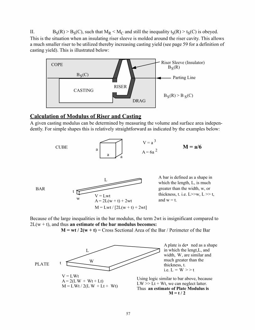
57
II. BS(R) > BS(C), such that MR < MC and still the inequality tS(R) > tS(C) is obeyed. This is the situation when an insulating riser sleeve is molded around the riser cavity. This allows a much smaller riser to be utilized thereby increasing casting yield (see page 59 for a definition of casting yield). This is illustrated below:
Calculation of Modulus of Riser and CastingA given casting modulus can be determined by measuring the volume and surface area indepen-dently. For simple shapes this is relatively straightforward as indicated by the examples below:
Because of the large inequalities in the bar modulus, the term 2wt is insignificant compared to 2L(w + t), and thus an estimate of the bar modulus becomes:
M = wt / 2(w + t) = Cross Sectional Area of the Bar / Perimeter of the Bar
CASTING
COPE
DRAG
Parting Line
BS(R)BS(C)
BS(R) > B S(C)
RISER
Riser Sleeve (Insulator)
CUBE aa a
V = a 3
A = 6a 2M = a/6
BAR
L
tw V = Lwt
A = 2L(w + t) + 2wtM = Lwt / [2L(w + t) + 2wt]
A bar is defined as a shape inwhich the length, L, is much greater than the width, w, or thickness, t. i.e. L>>w, L >> t,and w = t.
PLATE t
L
W
V = LWtA = 2(LW + Wt + Lt)M = LWt / 2(L W + Lt + Wt)
A plate is de• ned as a shapein which the lengt,L, andwidth, W, are similar and much greater than the thickness, t. i.e. L = W > > t
Using logic similar to bar above, becauseLW >> Lt + Wt, we can neglect latter.Thus an estimate of Plate Modulus is
M = t / 2

58
Location of Riser, Size and Shape of Riser
A riser or risers will be appropriately attached to the section of casting with the largest modulus. An example of a step bar is shown below:
This casting is represented by 3 plates with moduliMA = 0.25 / 2 = 0.125 in.MB = 0.5 / 2 = 0.25 in.MC = 1.0 / 2 = 0.5 in.
Since MB > 1.1 MA and MC > 1.1 MB, then the B section of the casting acts as a riser for A and thus the C section will act as a riser for B.There fore a riser will be needed only to successfully feed the heaviest section of the casting, sec-tion C. Choices include a top riser at point T or a side riser at point S on the large end of the step bar. Both choices will be effective feeders, the actual one chosen being determined by a number of other practical factors. More often the side mounted riser is chosen for ease of removal.Riser Shape-
The most efficient shape for a riser is a sphere, a shape which minimizes the surface area to volume ratio thereby maximizing V/A. However, practical molding considerations favor cylin-drical shapes with a height approximately 2 times the diameter (h = 2d).For this h/d ratio it can be shown that (A good student exercise) the moduli of the top and side mounted risers are:
Top Riser, MR = 2d / 9Side Riser, MR = d / 5
12”
4”
4”4”
1”
1/2”1/4”
A B C
T
S

59
Thus a side riser on the step bar requires a riser with a modulus MR = d/5 = 1.1MC = 0.55 in.
This is an adequate size riser for this casting. However it is important to make sure the riser con-nection is large enough so that it does not solidify before the casting. Because of the complexity of the heat transfer situation near the gate connection, they are often arrived at by trial and error.The effectiveness of a riser is also determined by whether the riser is considered “hot” or “cold”. Hot and cold risers are defined in terms of their relationship to the gating system of the casting. This is illustrated in the top view of a system containing both a hot and a cold riser.
Clearly from a fundamental heat transfer point of view the cold riser needs to be larger than the hot riser to accomplish feeding equivalent casting section sizes. Risers are also classified as blind or open, these varieties being defined in the sketch below:
2.75” 5.5”d h
A schematic side view of the casting would look like this.
AB
C Riser Connection
Casting
Base ofDown Sprue Riser 1
“HOT”Riser 2
“COLD”
All Molten Metal Entering TheCasting Passes Through the “HOT” Riser Thereby Heating and MakingIt More Ef fective
Path of Metal Flow
The Molten Metal that EntersThe “COLD” Riser Has AlreadyPassed Through the Casting, is only a portion of the Metal Enteringthe Casting and is therefore Colder
Runner
OPEN RISER (Open to Atmosphere) BLIND RISER (Surrounded by Sand)

60
Number of Risers-The number of risers needed to effectively feed a casting depends upon casting geometry
and feeding distance required. This can be illustrated by considering the two bar castings shown below:
The modulus of both bars is given by the estimate, MC = Cross Sectional Area (4x4) / Perimeter (16) = 4x4 / 16 = 1 The minimum requirement is that one riser with a modulus, MR = 1.1 would be sufficient. Using the top riser formula for a riser with h = 2d, MR = 2d / 9, gives a cylindrical riser with d = 4.95” and h = 9.9”. Common sense would tell one that the best position for the riser in each case would be in the middle of each bar at the positions marked R on the sketch. Thus the riser on the short bar would be required to feed all of the shrinkage in the 16 inch bar, while the same riser on the long bar would be required to feed 100 inches. While this may be satisfactory for the short bar, common sense again tells us that it is likely that the long bar would contain some shrinkage along the centerline of the bar, perhaps not near the riser or at the ends of the bar but in the mid regions indicated on the sketch with o’s. In fact, sectioning the bar along the centerline would reveal a situation similar to the sketch for the long bar. Apparently each riser and each bar end is effective at promoting a sound (NO VOIDS) casting immediately adjacent to either the bar end or the riser. The sound distance from the riser along the bar is said to be the Riser Effect, RE shown on the sketch, and the sound distance from the end of the bar is said to be the end effect, EE, both of which are shown on the above sketch of the 100” bar.Work on steel bar castings has shown that the gradient in temperature along the centerline, dT/dx, is a critical parameter in relating to whether voids form or not. It was shown from steel bars which
t = 4”, w = 4”
16” 100”
t = 4”, w = 4”R R
oooooooooooooo oooooooooooooRE EE

61
were instrumented with thermocouples along the centerline that voids were likely when dT/dx fell below a certain amount.. This is shown schematically below:
It can be seen in the above figure that the gradient, dT/dx, is greatest at the end of the bar in con-tact with the cold mold and at the riser in contact with the hot reservoir of molten metal. It was observed that when dT/dx at any time was less than a critical minimum value, (dT/dx)C, that shrinkage voids formed at the centerline. Of course, the longer the distance between the end of thebar and the riser, the more likelihood of voids. This then explains in a more rigorous way why the voids show up in the long bar on the previous page and not in the short bar.Thus each end of the bar and each riser is responsible for producing sound material. Selection of the number of risers needed then requires that the RE and EE for each material be known and then the risers positioned so that the RE and EE overlap, or at least butt together. For steel bar type castings it has been determined that RE = 1.5 t and EE = 2 t. Thus for a bar with t = 4”, the RE = 6” and the EE = 8”, and then the farthest distance that a riser can be placed from the end of a bar and still result in a sound bar would be the distance RE + EE = 14”. The contribution to sound bar castings from each riser would then be the riser diameter plus 2RE (feeding in both directions). For the 4” bar above, then, the maximum distance fed for each riser is 4.95 + 12 = 16.95”. Deter-mination of the number of risers needed for the 100” bar is determined as follows:
No. of Risers = (100 - 2EE) / (2RE + d) = 4.96, or 5 risers distributed uniformly along the length with the end risers 14 inches from the end of the bar.
Casting Yield
The casting yield is defined as the ratio :Casting Yield (CY) = Weight of Castings Shipped x 100%
Weight of Metal PouredIt is obvious that the goal for a metal casting plant would be to make casting yield as high as pos-sible. It is also obvious that the riser size and number of risers has a big impact on the casting yield. It is common practice for metal casting plants to have overall casting yields of between 40 and 80%. Maximization of the yield will involve reducing the number and size of the risers as an
InstrumentedCenterline
Riser
(dT/dx) 1
(dT/dx) 2
(dT/dx) 3
AT SOME TIME, t, AFTER POURING

62
important contributor. Of course, reducing the size of the gating system will also have a signifi-cant effect on casting yield. Two of the most common ways to increase yield are (1) to add insu-lating riser sleeves so that BS (R)can be increased (see earlier discussion) and (2) to add “chills” to the mold to induce stronger thermal gradients (dT/dx) thereby extending the end effect, or to actually add end effects in between risers. This effect of ”chills”, usually blocks of iron or other metal set into the mold, is illustrated below:
The actual increase in length of sound casting due to chills varies from one material to the next, but for steel bars a chill on the end of the bar will increase the EE by the bar thickness,t, while chills placed between risers will add at least an EE in either direction.IX. Heat Transfer and Solidification in Permanent Molds
Heat transfer between liquid metal and a permanent mold can also be described mathemat-ically in much the same way as was done for heat transfer in insulating molds. The major differ-ence here is that the mold material has a much larger thermal conductivity than sand, and so the solidification will be much more rapid. In the insulating mold the rate of transfer in the sand was the rate limiting step. In permanent molds the rate limiting step is at the interface between the metal and mold, where heat is transfered between the solidifying metal and the permanent mold, a mold which is usually coated with a mold wash or may quickly develop an air gap. The parameter which defines the transfer of heat between metal and mold in these cases is called the heat transfer coefficient, h. The model describing this event is illustrated below:
Notice in this schematic that the temperature drops discontinuously at the mold - casting interface. Heat flow within the casting and in the mold is very rapid (High Thermal Conductivity) compared
EE + t RE RE + EE RE + EE RE EE
“CHILLS”
Permanent MoldMolten Metal
Distance + xx - 0
Heat Flow Rate Across Interface
dQ = - Ah[T m - T0]dt

63
to the relatively slow transfer across the interface. Thus the rate of heat removal and therefore solidification rate depends on the heat transfer coefficient, h, across the interface. The total heat flow in time t is then given by integrating the above expression, giving:
and therefore for the solidification time,tS:
Using the relationships for Latent Heat and Superheat given earlier, and solving for tS gives:
Writing an expression which is a similar to Chvorinov gives:
tS = BS(V/A),
where BS is a mold constant and V/A is the modulus of the casting.It should be noted that, as opposed to solidification in a sand mold in which tS varies as the square of the casting modulus, solidification in a permanent mold varies linearly with the casting modulus.
Finite Element Analysis of Solidification in a Permanent Mold - Die Casting
Solidification of castings is a process which is quite complicated because of the many variables which affect the flow of heat during solidification. Some of these variables include:
• Position of Gates and Risers• Manner in which the Molten Metal Enters the Mold Cavity• Mold Cavity Temperature and Uniformity of Temperature• Fluid Movement during Solidification• Pouring Temperature and Time of Pouring• Mold Material, Interface Material• Degree of Separation Between Mold and Metal During Solidification etc.
Analytic solutions to solidification in complex shaped castings becomes nearly impossible because of the varied contributions from all of the above variables. Therefore engineers are rely-ing on the finite element analysis (FEA) approach to solve these problems with the help of the powerful computers that are now available. The discussion to follow makes an attempt to develop
Q Ah Tm T0−[ ] t−=
QS Ah Tm T0− tS−=
tSρMetal ∆HF CMetal Tp Tm–( )+[ ]
h Tm T0–( )--------------------------------------------------------------------
VMetalAMetal-----------------
=

64
the logic used in FEA to describe a simple solidification problem involving a molten aluminum cube in a steel mold.Consider the following simple casting:
Using the above simplified equation for solidification time in a permanent mold and constants given in Table 7 gives:
tS = 2.385(g/cm3) {[395.995 + 1.080(704-660)](joule / g) / 1.3058 joule / sec cm2 oC / (660-149) (oC)} ( 0.666 cm)=1.055 sec
Of course, this result reflects the assumption that the mold does not change temperature and there is no indication of when solidification is complete in various places within the casting. A more realistic representation would involve determining temperature variations within the steel and alu-minum and measuring solidification times in various places within the casting. This will be done by using the FEA method to first, divide the aluminum and steel into “nodes”, and second to determine the rate of heat transfer between nodes in discrete time intervals. This method is, of course, amenable to doing by computer iterations from one discrete time interval to the next. Con-sider the following Two Dimensional Nodal Map of the aluminum and steel at time t = 0. This map shows only one quarter of the casting and mold because symmetry conditions dictates that the remaining three quarters will behave in exactly the same manner as the one quarter.
AluminumCasting
Steel Mold
Air At t = 0 time
TAl = 704 oC (1300 oF)
TSt = 149 oC (300 oF)
TAir = 22 oC (72 oF)
hAl-St = 2300 BTU / hr ft 2 oF
= 13058 joule / sec m 2 oC
hSt-Air = 1.75 BTU / hr ft 2 oF
= 9.93 joule / sec m 2 oC4 cm
4 cm
Steel mold = 2 cm thick
1 2
3 4
5 6
7 8
9
10
11
12
13
14
15
16
Al Steel
(704)
(149) (149)(149)
(149)(149)(149)(149)
(149)(149)
(149)(149)
(149)
(704) (704)
(704)Initial T = 704 oC Initial T = 149 oC
ASSUME:1. Temperature within each Node is uniform and
2. Temperature changes by conduction betweennodes of similar material, where
3. Temperature changes by interfacial transferbetween nodes of dissimilar material.
dQ/dt = KA (Tn1 - Tn2) / x.
dQ/dt = hA (Tn1 - Tn2)4. Heat • ows perpendicular to the node walls.5. Heat does not • ow in or out of the page.Air = (22)

65
In the above equations, Q is heat in joules, K is the appropriate thermal conductivity of the metal-lic materials (either Al or Steel), the Tn’s are the temperatures of the nodes, A is the cross sec-tional area of each node face (1cm2), x is the distance between node centers (1 cm), and h is the heat transfer coefficient that applies.Integrating the above equations over the time step ∆t gives the relationships shown below for heat flow due to conduction and interface transfer. The final temperature of a node, Tf, resulting from the sum,ΣQ, of the heat components into or out of a node during the time interval ∆t is also given below, where Ti is the initial temperature, V is the volume of the node, ρ is the density of the node material, and C is the heat capacity of the node material.
and
The appropriate constants for computation of the Q’s and Tf for each node after each time incre-ment can be obtained from the above numbers for heat transfer coefficients on page 63 and the data in Table 7 on page 50 of these notes.
Initial Time Increment, ∆t = 0.1 sec
Nodes 1 and 13 do not change temperature during the first increment of time because the surrounding nodes have identical temperatures. Only those nodes in contact with a different mate-rial respond with heat flow in the first 0.1 sec time interval.
Consider nodes 2 and 5 , shown schematically below.
In the first time increment ∆t = 0.1 sec, 72.21 joules of heat flows across the node boundary, leav-ing the liquid Al and entering the solid steel mold. This is the only heat flow for either nodes 2 or 5 in the first time increment because there are no other temperature gradients to which these nodes can respond.(Recall that this is only two dimensional heat flow. We are not allowing heat flow into or out of the page for simplicity.) Clearly then after 0.1 sec the temperature of node 2 decreases and the temperature of node 5 increases by an amount determined by the heat capacity (specific heat) of each unit and the mass of the unit. Removing 72.21 joules from node 2 results in a temperature decrease after 0.1 sec from T2 = 704 to :
Q KA Tn1 Tn2–( ) ∆t( ) x⁄( )[ ]= Q hA Tn1 Tn2–( )∆t=
Tf T iΣQ
Vρ C+=
2(704)
5(149)
Q = h Al-StA(T2 - T5)∆t
Q
Q = 13058 . (0.01) 2 . (704 - 149) . 0.1Q = 72.21 joules

66
T2 = 704 - 72.21/[13 (2.385) (1.117)} = 704 - 27.1 = 676.9 oC
Adding 72.21 joules of heat to node 5 results in a temperature increase from 149 to:
T5 = 149 + 72.21 / [13 (7.87) (0.456)] = 149 + 20.12 = 169.12 oC
By symmetry, nodes 3 and 9 are identical to nodes 2 and 5. Nodes 4, 7, and 11 experience change in the first 0.1 sec as follows. Heat will flow from 4 to 7, and 4 to 11 in the same manner as from 2 to 5 above. Thus nodes 7 and 11 will have the same temperature increase as node 5, from 149 to 169.12oC. However node 4 will have twice as much heat extracted as node 2 and so the tempera-ture will be lower than in node 2.
Superheat and Latent Heat to be removed before Solidification is complete.
At this point it is necessary to ask the question: How much heat must be extracted from a molten Al node before the melting point is reached, and then before the latent heat is extracted?
Superheat in 1 cm3 Al at 704 = CρV∆T = (1.085) (2.385) (1) (44)= 113.86 joulesLatent Heat in 1 cm3 of Al = ∆HFρV = (395.995) (2.385) (1) = 944.45 joule
Thus a total of 1058.31 joules of heat needs to be removed from a node of pure Al at 704 oC before solidification is complete in that node. Because node 4 has twice as much heat removed than node 2 in the same time increment, 144.42 joules, node 2 will already have begun to solidify because more heat than the superheat has already been removed. An estimate can be made of the fraction of solid present by the ratio: (144.42 - 113.86) / 944.45 = 0.032, or 3.2% of the Al in node 4 has solidified. Thus the temperature of node 4 is 660oC, and will remain there until the solidifi-cation is complete; i.e. until the remaining 914 joules of latent heat have been removed. The steel nodes bordering the air at 22oC, nodes 6,8, 10,12, 14, 15, and16 will also undergo a reduction in temperature by the amount:
T6 = 149 - (0.000993) (1) (127) (0.1) = 149 - 0.0126 = 148.9874
Obviously because of the very small heat transfer coefficient between steel and air, the tempera-ture decreases only a very small amount for those nodes on the outside of the steel mold. Thus the

67
temperatures (rounded off to the nearest degree) in the 16 nodes after the first 0.1 sec of the FEA is given below:
The Second Time Increment, ∆t = 0.1 sec (Total Time = 0.2 sec)
The next iteration in the FEA involves more of the nodes in the system because of the temperature changes resulting in the first time increment. Consider node 1, which now has thermal gradients between itself and nodes 2 and3.
Consider node 2 once again. Node 2 has three inputs to heat flow in the second time increment, illustrated below:
1 2
3 4
5 6
7 8
9
10
11
12
13
14
15
16
Al Steel
(704)
(149) (149)(149)
(149)(149)(169)(169)
(149)(169)
(149)(169)
(149)
(677) (660)
(677)Initial T = 704 oC Initial T = 149 oC
Air (22)
Notes:1. Node 4 has partially solidi• ed, ~ 3.2%
Shown as dark shaded area.
AFTER TIME 0.1 SEC
1 2
3
The net heat change in node 1 is given by:ΣQ = Q 1->2 + Q 1->3ΣQ = + (0.9403) (1) (677 - 704) (0.1)
+ (0.9403) (1) (677 - 704) (0.1)=5.0776 joules
Thus the temperature of node 1 after 0.2 sec isT1 = 704 -5.0776 / [1 3(2.385)1.1 17)]
(704) (677)
(677)
1 2 5
4
Thus the net heat change in node 2 is given by:ΣQ = Q 1->2 + Q 2->5 + Q 2->4ΣQ = + (0.9403) (1) (704 - 677) (0.1) / (1)
+(1.3058) (1) (169 - 677) (0.1)+(0.9403) (1) ( 660 - 677) (0.1) / (1)=2.539 - 66.334 - 1.598 = - 65.394 joules
From knowledge of heat content of Al, only 41.65 joules of superheat remain in node 2,therefore node 2 will begin to solidify in time increment 2, having a fraction of:(65.39 - 41.65) / 944.45 = 2.5% solid, the temperature decreasing to and remaining at 660 oC.

68
A similar calculation for node 4 gives:ΣQ = + 2{(0.9403) (1) (677 - 660) (0.1) / (1)} + 2{(1.3058) (1) (169 - 660) (0.1)}ΣQ = + 3.197 - 128.229 = - 125.03 joules
This extraction of heat from node 4 removes latent heat only, and so the temperature of node 4 remains at 660oC. The total fraction of solid after increment 2 in node 4 is given by the ratio of:155.6 / 944.42 = 0.1647 or 16.47 % solid.Similarly it can be shown by summing the heat flows for the steel nodes that the temperatures will increase in the amounts shown below.
Nodes 5 & 9:ΣQ = 1.3058 (1) (667 - 169) (0.1) + [0.782 (1) (149 - 169) (0.1) / (1)] = 64.77 joule
Tf = 169 + 64.77 / [ (1) (7.87) (0.456)] = 187.05
Nodes 7 & 11:ΣQ = 1.3058 (1) (660 - 169) (0.1) + 2[0.782 (1) (149 - 169) (0.1) / (1)] = 60.99 joule
Tf = 169 + 60.987 / [ (1) (7.87) (0.456)] = 185.99
Node 13:ΣQ = 2[(0.782) (1) (169 - 149) (0.1) / (1)] = 3.128 joules
Tf = 149 + o.87 = 149.87
Nodes 6, 8, 10, and 12:ΣQ = (0.78) (1) (169 - 149) (0.1) / (1) + (0.00099) (1) (22 - 149) (0.1) = 1.55 joule
Tf = 149 + 1.552 / [(1) (7.87) (0.456)] = 149.432
Nodes 14, 15, & 16 lose only 0.012 joules, thereby changing only a fraction of a degree (no change).

69
The temperature distribution (rounded off to the nearest degree) after 2 increments of 0.1 sec time is illustrated below:
Thus solidification and the temperature distribution in the entire casting - mold configuration can be observed by systematically:
I Summing the Heat Flows into Each Node During Each Time IncrementII. Computing the Change in Nodal Temperature As a Result of That Heat Flow
Problem: Continue the heat flow scenario described above until solidification is complete in node 1.Report your results at critical periods in the process by:a. Including distributions like the above showing the progress of solidificationb. Including cooling and heating curves for nodes 1,2,4,5,7,13, and 16 on one graph.Clearly the best way to do this work would require a computer program to carry our your itera-tions. IT WILL BE ACCEPTABLE FOR GROUPS OF UP TO THREE PEOPLE TO TURN IN ONE PAPER.
X. Continuous and Semicontinuous CastingContinuous Casting of Steel
The objective of continuous casting is to produce large, simple shapes for subsequent forming operations, a process which has been carried to great lengths with the continuous casting of steel slabs and bars. Prior to the mid 1960s, all of the steel produced in the United States was done by casting into large ingot molds (usually cast iron) followed by ingot breakdown in the hot rolling mills, a relatively inefficient process both thermally (ingots would have to cool signifi-cantly for handling, and then be heated again prior to breakdown) and from a casting yield stand-point (approximately 80% of the ingot is usable for the production of semi-finished products). According to the 10th edition of “Making, Shaping, and Heat Treating of Steel”, continuous cast-ing of steel has had the greatest impact (of all technologies developed and applied in the steel industry) on improving the efficiency of material utilization, the yield increasing from 80% in
1 2
3 4
5 6
7 8
9
10
11
12
13
14
15
16
Al Steel
(702)
(149) (149)(149)
(149)(150)(186)(187)
(149)(186)
(149)(187)
(149)
(660) (660)
(660)Initial T = 704 oC Initial T = 149 oC
Air (22)
Notes:
1. Node 4 has partially solidi• ed, ~ 16.5%
Solidi• ed part shown as dark shaded area.
AFTER TIME 0.2 SEC
2. Nodes 2 and 3 have partially solidi• ed, ~2.5%

70
ingot casting to 95% in continuous casting. The growth of continuous casting of steel in the United States as well as the demise of ingot casting is shown in the Figure below:
The continuous casting process is illustrated below together with a schematic of a conventional ingot mold.
The process of continuous casting involves supplying a tundish (storage and transfer vessel) with molten steel and then metering that steel into a water-cooled mold whose bottom is the steel billet or slab. This slab or billet is bent as it moves and large conveniently sized pieces are cut or sheared for further processing. It should be noted that the liquid sump can extend a significant dis-tance down into the casting. The operators must be careful so that remelting doesn’t occur and cause a runout. Other advantages over conventional ingot casting in addition to increased effi-ciency include higher production rates, and finer microstructures (smaller dendrite arm spacings) due to water cooling the smaller cross-section castings. The finer dendrite arm spacing is a struc-ture which is more easily deformed and less likely to fail during that mechanical processing. In addition, the larger section ingot castings are more likely to be plagued by macrosegregation, in which segregation due to gravity differences produce significant change in chemical composition from one point to another on a macroscale.
1960 1968 1976 1984 1992 2000Year
100
80
60
40
20
0
Data From “Making, Shaping,and Heat Treating of Steel”, 10th Ed.& 1995 AISI Statistical Report
ContinuousIngot
United StatesSteel Production
Water Cooled Mold
Water Spray
Liquid Steel Sump
Solid Steel
Saw or Shear
Tundish Conventional Ingot

71
Semi - Continuous casting of Aluminum Alloys, Free machining brass
Continuous casting is clearly the most efficient way to produce stock for further mechanical pro-cessing of metals. However the casting of non-ferrous alloys based on aluminum or copper is most often done in a semi-continuous mode, a schematic of which is indicated in the above figure. Initially the base block is snug up against the water-cooled mold. Casting commences by pouring directly onto the base block and then moving the base block downward as solidification progresses. There is no attempt to bend the casting. Rather the casting extends down into a well, typically 20 to 30 feet deep. When the base block reaches the bottom of the well the casting pro-cess is over. Most aluminum alloys produced for wrought applications are made this way, produc-ing ingots about 20 feet long by 3-4 feet wide by 1.5-2 feet thick. Free machining brasses (Cu-35Zn-3Pb) are produced in a similar way with three cylindrical “logs” produced simultaneously with dimensions of about 12 inches by 20 - 30 feet long. Advantages of this technique over static cast ingots are the same as given above for the continuous cast steel. Continuous casting of some non-ferrous products does occur but the relative proportion is quite small.
Tundish
Water Cooled Mold
Water Spray
Base Block
Solid Casting
Liquid Sump

72
Microstructure of Continuous and Semi-continuous CastingsThe microstructure of castings produced in this way is illustrated below:
This schematic illustrates the basic process of grain (dendrite) nucleation and growth in a continu-ous cast billet. The above cross section illustrates the three common grain structures observed in these types of castings. The outer “chill” layer is made up of a very fine equiaxed grain structure which has nucleated as a result of the large undercooling present at the surface. This quickly changes to a columnar structure which extends from the chill layer in towards the center of the casting, the columnar (long and narrow) grains (dendrites) being extensions of chill grains (in favorably oriented [100] directions) which grow parallel to the direction of heat flow. During the columnar growth time, nucleation of new grains (dendrites) occurs in the remaining liquid volume in the center of the billet, grains which grow in an equiaxed manner into the remaining liquid. Solidification is complete when the columnar grains encounter the growing equiaxed grains. It is thought that the nuclei which ultimately end up as the equiaxed grains in the center come from the growing columnar dendrites, where secondary arms have broken off of the columnar dendrites (as a result of chemical, mechanical or thermal instabilities in the melt) and have been swept out into the liquid. These nuclei then either survive and grow giving the equiaxed grains, or are remelted in the remaining liquid allowing the columnar grains to grow to the center of the casting. The occurrence of the columnar zone is not a favorable structure for hot working processes, the con-tact area between columnar zones at right angles to each other being a dumping ground for seg-regants, porosity, inclusions, etc. which become effectively planes of weakness (see the above schematic) in the casting. It is therefore desirable to produce castings which have no columnar zone, a situation which is favored by reducing the superheat (increasing the chances of nuclei sur-vival in the center), or by stirring the liquid thereby mechanically removing some dendrite arms for transport to the central part of the casting. Stirring can be accomplished in certain instances
Typical Continuous Cast Billet Grain Structur e, As-Solidi• ed
Chill Zone - Equiaxed, FineGrained Structure on surface
Columnar Zone -ElongatedGrains extending from ChillZone toward Center of Billet(originate as favorably oriented chill zone grains)Equiaxed Zone - Equiaxed,Large Grains which form inthe last part of the billet tosolidify.
of casting (many nuclei)
Q
Q
Q Q
Q = Heat
Plane ofWeakness

73
electromagnetically, and in other cases by shaking or moving the casting to generate shock waves which affect the arms of the growing dendrites. The idea of chemical, thermal, or mechanical forces dislodging dendrite arms to send them into other parts of the solidifying casting can be bet-ter understood when the physical shape of these dendrite arms is considered.This reality is described in the schematic below:Photographs of dendrites in real crystals inevitably reveal situations which look remarkably like the above sketch. There is no direct proof that these “released” arms are in fact the source of the equiaxed grains in the center of the castings, but the circumstantial evidence is almost over-whelming.
XI. Solidification, Binary SystemEquilibrium Solidification
Equilibrium solidification in a binary sys-tem assumes that diffusion occurs within the solid and adequate mixing occurs in the liquid so that the compositions described by the phase diagram are obeyed. The attached schematic phase diagram is used in the description of both equilibrium and non-equilibrium solidification. During equilib-rium solidification the first phase to appear is the terminal solid solution α of composition kCo at the temperature TL, where k is the equilibrium distri-bution coefficient and Co is the alloy composi-tion.The equilibrium distribution coefficient is defined as the ratio of the composition of the solid to that of the liquid at a given temperature, a value which can be determined from the phase diagram. Solidification is complete at temperature T0 and the composition of solid reaches Co. The lever rule can be used to compute the weight percentage of the phases α & β present in the temperature range TL to T0. Non Equilibrium Solidification
In real situations involving solidification, the largest departure from equilibrium results from the fact that diffusion in solids usually cannot maintain equilibrium in the solid state during solidification. In alloys with substitutional solute atoms which diffuse by a vacancy mechanism, the number of vacancies and the statistical nature in which they move preclude the solid phase maintaining the composition required by the phase diagram during the time available to the solid-ifying casting. Only those solutes which are interstitial and have mostly empty neighboring sites (carbon in iron for example) can even hope to keep up with the dictates of the phase diagram. In the above figure, then, the composition kCo of the initial solid to form remains at or near that value during and after casting. With cooling below TLthe new solid to form will obey the phase diagram and be richer in solute than the first to form. The net result of this is that when the tem-perature T0 is reached THE AVERAGE COMPOSITION OF THE SOLID α IS LESS THAN Co and there is still some liquid left; the casting must go to lower temperatures before solidification is
Wt. Pct Solute
Tem
pera
ture
�
�
�������������
Co
�������������������������������������������
�
�
������������
kCo
α
TL
T0
α + β
α + L
Liquid, L
TE
L + β�
�
�������
�
�
�������
CECM

74
complete. In eutectic systems like the one shown above, the final temperature of solidification will in fact be the eutectic temperature, TE. The practical result of this situation is that real cast-ings are not homogeneous in composition throughout, with alloy segregation occurring on a microscopic scale. The Scheil Equation
The simplest way to illustrate this non-equilibrium situation is to consider the one dimen-sional solidification of an alloy of composition Co under the conditions where NO SOLID STATE DIFFUSION OCCURS and WHERE COMPLETE MIXING IN THE LIQUID OCCURS; i.e. the liquid maintains equilibrium with the solid interface during cooling and the solid interface will change composition in equilibrium with the homogeneous liquid. This can be visualized by con-sidering the following schematic ONE DIMENSIONAL solidification process where the solid - liquid interface will move as a planar interface from right to left in response to the heat being extracted to the left.
In the above sketch it can be seen that the solid composition starts at kCo on the left and then gradually increases in a non-linear fashion as solidification progresses to the right increasing until the maximum solubility of solute in α is reached , CM at TE. At the same time the liquid compo-sition increases overall until the eutectic composition is reached at the eutectic temperature. At this point the remaining liquid will undergo a eutectic reaction forming α + β. It can be shown
Liquid (Complete Mixing)
Solid
Solid
Solid (No Solid State Diffusion)
Q
Q
Q
Q
Solu
te C
ompo
sitio
n (W
eigh
t %)
kCo
Co
CE
� �������������������������������������������������������������������������������������������������������������������������������������������������
� ������������������������������������������������������������������������������������������������������������������������������������������������
� ������������������������������������������������������������������������������������������������������������������������������������������������
�
�
�������������������
��
��
������������������������������
�
�
��������
��
��������������������������������������������������
� ����������������������������������������������������������������������������������������������������������������������������������������������������������������������������������������������������������������������������
���
��
��
��
������
��
��
������������
t = 0
t = t1
t = t2
t = t3T = TE
T = TL
Fraction Solid, f
����
��
�������������������������������������������������� Liquid Composition
Solid Composition
0 1
� ��������������������������������������������������������������������������������������������������������������������������������CM

75
that the equation describing the non-linear solid composition, CS, from left to right is known as the Scheil equation, given below:
CS = kCo {1/(1- f)}1-k
This variation in composition describes quantitatively the segregation of solute in a binary alloy which has solidified under these one dimensional conditions of planar interface movement. Of course most real solidification events involve the formation and growth of dendrites, which is not a planar solidification event on a macroscale. However on a microscale during solidification between dendrite arms, the planar front description is a fairly accurate representation of dendrite arm fattening after the dendrite has already been established. This is shown in the following schematic representation of dendritic growth.
It can be seen in the above sketch that the fattening of dendrite arms mirrors on a microscale the one dimensional growth pictured on page 74. Even though the conditions of solidification on a macroscale is definitely not planar front solidification (dendritic growth is quite the opposite of planar front solidification in which the dendrite arms race out into the liquid in response to com-positional and thermal fluctuations at the solid - liquid interface) the conditions for growth (fat-tening) in between dendrite arms approximate the conditions of no solid state diffusion and complete mixing in the liquid required to develop the Scheil Equation. This is because the den-drite arm spacing is quite small, on the order of 10 to 100 microns (0.01 to 0.1 millimeters), and liquid state diffusion is rapid enough to accomplish mixing in the microvolume between dendrite arms. Typically liquid state diffusion coefficients are on the order of 10-6 cm2 / sec. Using the time tested relationship between the distance an atom can move x, and the diffusion coefficient D, and time t, [x = (Dt)1/2] , gives x = 0.1 mm for a reasonable solidification time of 100 seconds. This means that atomic diffusion of solute within the liquid is sufficient to maintain a reasonably uniform composition in those microvolumes. In the schematic above the final product consists of
���������������������������������������������������������������
���������������������������������������������
������������������������������������������������
��������������������������������������������������
��������������������������������������������������
������������������������������������������������������������
�
�
�������������������������
�
�
�������������������������
�
�
�������������������������
Solu
te C
ompo
sitio
n
� ���������������������������������������������������������������������������������������������������������������������������
� ��������������������������������������������������������������������������������������������������������������������������
�� ��������������������������������������������������������������������������������������������������������������������������
�� ��������������������������������������������������������������������������������������������������������������������������CE
CM
CokCo
�
�
���������������
�
�
��������������
��
��
��������������������������������������������������
�
�
��������������
�
�
���������������
�
�
�������������������������
�� �����������������������������
Dendrite Arm Fatteningd, Dendrite Arm Spacing
LiquidEutecticCored
SolidCored Solid
Dendrite Arm Lengthening
Coring (No SSD, CompleteMixing in Liquid)
Scheil Equation Relationshipin solid dendrite illustratingMICROSEGREGATION OFSOLUTE (Copper in Al)

76
dendrite arms (the center of which represents the first to freeze (FTF) part of the casting) with a gradient of solute perpendicular to the dendrite arm (coring) and a volume of eutectic product between the dendrite arms representing the last to freeze (LTF) part of the casting. This is a very common configuration in commercial cast microstructures. Of course most commercial cast materials are multicomponent alloys in which there may be several major solute species added for one reason or another. Those solutes with equilibrium distribution coefficients, k, less than 1 (Cu in Al) will segregate in the manner shown above, solutes described as positive segregants. Sol-utes with an equilibrium distribution coefficient greater than 1 (Ni in Fe) will segregregate in the opposite way, with decreasing solute content as the dendrite fattens. These solutes are said to seg-regate negatively. XII. Aluminum Alloys
Aluminum is a very important metal because of its low density and excellent mechanical properties, properties which stem largely from its face centered cubic crystal structure. It is alloyed with elements like Mg, Si, Cu, Mn, Fe, etc. to produce a variety of wrought products from beverage cans to aircraft structural parts, to cast products like engine blocks and steering knuckles for automobiles. The figure below illustrates the amounts of primary and secondary aluminum produced and the amount shipped in the year 1989 for beverage can and casting production:
It can be seen that the bulk of the aluminum produced in the U.S. goes into the production of wrought products. An example of the largest single product tonnage-wise is the production of beverage cans; more aluminum is used in the production of beverage cans in a given year than is used in the production of castings for all applications. Another significant industrial fact is that a large fraction of the secondary aluminum production comes as a result of the recycling of bever-
Primary
4.03
Numbers in Million Metric Tons (1989 Data)
SecondaryAluminum
2.05
New1.04
Old1.01
Aluminum
U.S. Production of Al
BeverageCans1.37
Castings
Sand0.112
Permanent& Semi-
Permanent0.196
Die0.690
Aluminum Statistical Review for 1990; The Aluminum Association
Wrought
& Cast
Products
Partial U.S. Consumption of Al

77
age cans; about 60 percent of the material used to produce beverage cans in 1989 were recycled through the secondary market, a good source of material for casting production.Aluminum Casting AlloysThe most important aluminum casting alloys, on a tonnage basis, are those which depend upon the eutectic reaction to improve castability, to lower energy input and pouring temperature, and to produce desirable cast microstructures. These aluminum alloys contain primarily Si, Mg, and Cu. The details of the phase diagrams for binary and ternary alloys containing these elements can be found in the appropriate handbooks. Details of aluminum foundry products and cast aluminum properties are given in the Metals Handbook, ninth edition, pages 140 - 179; the student is encour-aged to read those sections.
Processing and Microstructure of Several Selected Al - base Si Alloys
Alloy 356.2 (Nominal Composition 7 Si, 0.1 Cu, 0.35 Mg, 0.05 Mn, 0.12 max Fe)This hypoeutectic Al - Si base alloy represents an important aluminum casting alloy, an
alloy utilized for higher strength and ductility automotive and aircraft applications. The function of the alloy elements present are as follows:
Si - Lowers solidification temperature, promotes good castability, improves wear resistance.Mg - Combines with Si during heat treatment to produce Mg2Si precipitates in the aluminum rich a matrix.Cu - Strengthens matrix by solid solution strengthening and through precipitation hardeningFe - minimum amount reduces negative effect of platelets of Fe2Si2Al9.
Solidification of 356.2Solidification of this material involves the production first of proeutectic aluminum rich α
dendrites followed by the formation of the eutectic product containing primarily aluminum and platelets of silicon. A schematic cooling curve for such a solidification event is given below:
577 0C
660.4 0CLiquid, L
α
α + L
α + β
L + β
Weight Percent Si
12.61.65
7Time
Proeutectic α
Eutectic α + β

78
Schematic microstructures similar to this alloy are shown in the first laboratory handout. The presence of Mg and Fe in this alloy gives an opportunity for the formation of a chinese-script eutectic of α + Mg2Si and platelets of Fe2Si2Al9 in addition to the Si platelets. These plate-shaped phases produced in typical sand castings provide easy crack nucleation sites and propagation paths , thereby resulting in relatively low strengths and ductility.Modification of 356.2In applications where strength and ductility are not important, the sand castings with the plate-shaped second phase morphology is considered acceptable. However, higher strengths and ductil-ities can be realized by the addition of small amounts of Na or Sr to the melt (a process called modification) just prior to pouring the castings (See section on additives in these notes). This additives effectively changes the shape of the silicon from plates to rods thereby reducing the crack nucleation and propagation potential. See the schematic modified microstructure in the lab-oratory handout #1. This process has the potential to double the ductility and increase the strength by 25 %.Age Hardening 356.2Following solidification, the 356.2 alloy castings can be further strengthened by precipitation of the Mg2Si as fine coherent particles within the a matrix. [The student is urged to consult an appro-priate physical metallurgy text for a basic description of the fundamentals of precipitation harden-ing.] The heat treatment schedule needed for this process is given below together with a quasi-binary phase diagram for the aluminum - Mg2Si system:
The solution treatment time of 12 hours at 525 OC is designed to dissolve the eutectic Mg2Si par-ticles in the a solution (which formed as a result of segregation, coring, during solidification) and to redistribute the Mg and Si uniformly throughout. It is known that up to 1.85 wt. pct. Mg2Si (see above phase diagram) is soluble in the a matrix at 595 OC. If it is assumed that all of the Mg which is present in the alloy (0.35 %) can be taken into solution, this gives ~ 0.52 wt. pct. Mg2Si as potential precipitates on aging. Quenching into hot water is followed by aging at 155 for 3 - 5 hours during which time the coherent tiny strengthening precipitates of Mg2Si are formed in the a
α + Mg 2Si
L
α + Lα
131.85
Wt Pct Mg 2Si
660 0C
595 0C
Solution Treat
520 - 530
150 - 155
Aging Treatment
12 hour
Time
Water Quench65 - 100 0C 3 - 5 hours
Typical Heat Treatment Schedule

79
solid solution.The effect of aging time on the tensile properties of A 356.2 alloys is illustrated below:
Alloy 319.1 (Nominal Composition 6 Si, 3.5 Cu, 0.1 Max Mg, 1.0 Max Fe, 0.1 Max Ni)This is an important alloy used to produce castings in permanent molds, a hypoeutectic
alloy which, because of the presence of Cu, is also age hardenable. The major elements, Si and Cu, are present in an amount so that solidification proceeds in a similar way to alloy 356.2, namely by the production of proeutectic dendrites of α followed by a eutectic reaction in which both Si and Al2Cu can form in eutectic products surrounding the dendrites of α. A microstructure of this alloy could look like the schematic below:
Aging Time (Hours)0 2 4 6 8 10 12
25
30
35
40
45 Yield Strength
Percent Elongation10
8
6
4
2
0
Data From Shivkumar ,Keller & ApelianAFS TransactionsVolume 97, Pg 905 - 91 11990
������������������������������������������������������������������������������������������������������������������������������������������������������������������������������������������������������������������������������������������������������������������������������������������������������������������������������������������������������������������������������������������������������������������������������������������������������������������������������������������������������������������������������������������������������������������������������������������������������������������������������������������������������������������������������������������������������������������������������������������������������������������
������������������������������������������������������������
������������������������������������������������������������������������������������������������������������������������������������������������������������������������������������������������������������������������������������������������������������������������������������������������������������������������
��������������������������������������������������������������������������������������������������������������������������������������������������������������������������������������������������������������������������������
������������������������������������������������������������������������������������������������������������������������������������������������������������������������������������������������������������������������������������������������������������������
������
����������������������������������������������������������������������������������������������������������������������������������������������������������������������������������������������������������������������������������������������������������������������������������������������������������������
����������������������������������������������������������������������������������������������������������������������������������������������������������������������������������������������������������������
�������������������������������������������������������������������������������������������������������������������������������������������������������������������������������������������������������������������������������������������������������������������������������������������������������������
����
�����������������������������������������������������������������������������������������������
Al2CuSi
Fe - Containing PlateletsFe2Si2Al9
SectionThrough
DendriteArm
SDAS
� ������������������������������
�
���������������
�����������������������������
(β)
Cu
Si
Distance
Com
posi
tion
����������������������������������������������������������������������������������������������������������������������������������������������������������������������������������������������������������������������������������������������������������������������������
������������������������������������������������������������������������������������������������
Proeutectic
Eutectic α
Segregation ofCu and Si
due to “Coring”within dendrite

80
In this schematic micrograph the position of the proeutectic α dendrites are shown by dashed lines to indicate the imaginary boundary between dendritic α and eutectic α. The eutectic Si (β) is shown as platelets, the eutectic Al2Cu as individual particles, and the Fe-rich platelets all share the interdendritic volume with the eutectic α. In addition the segregation of Cu and Si within the dendrites (as a result of solidification) is shown as a positive segregation event; i.e. the composi-tion of both Si and Cu increases with increasing distance from the center of the dendrite. Like the 356.2 alloy, attaining the optimum in mechanical properties will involve a precipitation hardening treatment, solutionizing at about 500 0C (put the Al2Cu into solution and redistribute the Cu uni-formly in the dendrite arms) followed by hot water quenching and an aging treatment in the range 130 - 190 0C. Mechanical properties are in the same range as alloy 356.2. Further refinement of this material can be accomplished by modifying the eutectic with Na or Sr, like alloy 356.2, or by the addition of a grain refining agent such as TiB; the TiB additive is effective at providing more nucleation sites for the dendritic α product.Alloy KS 281 (German ) [Nominal 18 Si, 1.2 Cu, 1.1Mg, <1.3 Ni, <0.7Fe, <0.3 Mn, < 0.2 Ti]
This hypereutectic Al - Si base alloy represents a modern material used for the production of automotive pistons by a permanent molding technique, an application which requires good wear resistance and reasonable high temperature strength. In this alloy, the high silicon content ensures the formation of the hard, wear resistant proeutectic β (see the partial phase diagram on page 58) prior to the eutectic reaction in which the remaining liquid transforms to the Si and Al2Cu phases in the eutectic α matrix. The as - cast microstructure is illustrated schematically below:
The dominant feature of this microstructure are the blocky proeutectic Si - rich particles, the remaining structure being composed of the eutectic products mentioned above. Processing KS 281
Processing this material involves a special effort to refine the proeutectic product; a fine-scale distribution of the proeutectic product is more desirable than a coarse distribution. This is accomplished by the addition of 60 - 80 ppm (parts per million) of phosphorous, added to the melt
������������������������������������������
������������������������������������������������������������
Proeutectic Si (β)
Eutectic Si (β)
Eutectic Al2Cu
Eutectic α

81
in the form of a Cu - P alloy after the degassing operation (Degassing is an important step in the production of Al alloy castings, a process described elsewhere in these notes).The addition of the phosphorous creates conditions for more nucleation of the proeutectic β during cooling of the casting. Strengthening of this material is accomplished by the same precipitation hardening pro-cess described for alloys 356.2 and 319.1. The details of this heat treatment include a solutioniz-ing step of ~ 1 hour at 510 0C, a hot water quench (70 0C for 8 minutes), and a 5 hour aging treatment at 230 0C. XIII. Additives To Molten Metal
Molten metal processing often involves a procedure where additives are introduced to the molten metal at some stage in the sequence of operations shown schematically below:
Points of addition in the sequence include during charging, tapping, mold pouring, and in the mold.The reasons for additions are many and varied, a number of these being listed below:
A. Alloying additions for control of chemical composition - these can be made in the furnace charge (A above) or at some point after the metal is molten. Amounts from 0 to several % are typically added. The choice of at what stage the alloy is added depends pri-marily upon the ease with which the alloy melts or goes into solution.B. Additions for the purpose of providing nucleation sites for a phase or phases - these are usually made at some point after charging. Amounts are usually small, and may be as small as 0.02 % to be effective. A classic example of this type of addition is the inoc-ulation process in gray and ductile cast irons. This process, where a ferrosilicon alloy is added for the purpose of nucleating graphite, varies from plant to plant and from casting to casting. Most plants inoculate at the tapping stage (B above) when the metal flows into the ladle, but may add “insurance” inoculant when the mold is poured (C above) or they may actually put a small amount of inoculant into the gating system (The so-called In-Mold Stage D above). In this process it has been shown that the later the addition point the more effective is the inoculant. It is also true that the later the addition the more expensive the process; it costs nothing extra to deliver a paper bag filled with inoculant at point B but may be quite expensive to deliver a controlled amount at points C and D. This class will experience the relative complexity of inoculation in the gating experiment on gray cast iron, in which we will attempt to deliver a controlled amount using Hickman - William’s commercial unit (The Post Inoculant Feeder PIF). The fact that lateness is important for effective inoculation implies that time in the metal is detrimental to the formation of nuclei. The inoculant is said to “fade” with time. Most processing requirements, for exam-ple, specify that the casting be poured no later than 10 minutes after inoculation if inocula-tion occurs at point B. If the time is exceeded then the molten metal is usually “pigged” to
������������������������������������������������������������������������������������������������������������������������������������������������������������������������������������������������������������������������������������������������������������
������������������������������������������������������������������������������������������������������������������������������������������������������������������������������������������������������������������������������������������������������������������������������������������������������������������������������������������������������������������������������������������������
������������������������������������������������������������������������������������������������������������������������������������������������������������������������������������������������������������������������������������������������������������������������������������������������������������������������������������������������
A. Charging
B. Tapping C. Mold Pouring
D. In-MoldFurnace Ladle
Mold
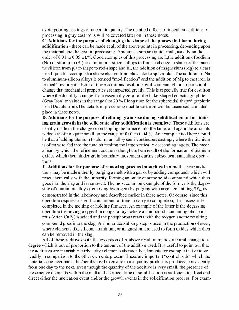
82
avoid pouring castings of uncertain quality. The detailed effects of inoculant additions of processing in gray cast irons will be covered later on in these notes.C. Additions for the purpose of changing the shape of the phases that form during solidification - these can be made at all of the above points in processing, depending upon the material and the goal of processing. Amounts again are quite small, usually on the order of 0.01 to 0.05 wt.%. Good examples of this processing are I.,the addition of sodium (Na) or strontium (Sr) to aluminum - silicon alloys to force a change in shape of the eutec-tic silicon from plate-shape to rod-shape and II., the addition of magnesium (Mg) to a cast iron liquid to accomplish a shape change from plate-like to spheroidal. The addition of Na to aluminum-silicon alloys is termed “modification” and the addition of Mg to cast iron is termed “treatment”. Both of these additions result in significant enough microstructural change that mechanical properties are impacted greatly. This is especially true for cast iron where the ductility changes from essentially zero for the flake-shaped eutectic graphite (Gray Iron) to values in the range 0 to 20 % Elongation for the spheroidal shaped graphitic iron (Ductile Iron).The details of processing ductile cast iron will be discussed at a later place in these notes.D. Additions for the purpose of refining grain size during solidification or for limit-ing grain growth in the solid state after solidification is complete. These additions are usually made in the charge or on tapping the furnace into the ladle, and again the amounts added are often quite small, in the range of 0.01 to 0.04 %. An example cited here would be that of adding titanium to aluminum alloy semi-continuous castings, where the titanium is often wire-fed into the tundish feeding the large vertically descending ingots. The mech-anism by which the refinement occurs is thought to be a result of the formation of titanium oxides which then hinder grain boundary movement during subsequent annealing opera-tions.E. Additions for the purpose of removing gaseous impurities in a melt. These addi-tions may be made either by purging a melt with a gas or by adding compounds which will react chemically with the impurity, forming an oxide or some solid compound which then goes into the slag and is removed. The most common example of the former is the degas-sing of aluminum alloys (removing hydrogen) by purging with argon containing SF6, as demonstrated in the laboratory and described earlier in these notes. Of course, since this operation requires a significant amount of time to carry to completion, it is necessarily completed in the melting or holding furnaces. An example of the latter is the degassing operation (removing oxygen) in copper alloys where a compound containing phospho-rous (often CuP3) is added and the phosphorous reacts with the oxygen andthe resulting compound goes into the slag. A similar deoxidizing step is used in the production of steel, where elements like silicon, aluminum, or magnesium are used to form oxides which then can be removed in the slag.All of these additives with the exception of A above result in microstructural change to a
degree which is out of proportion to the amount of the additive used. It is useful to point out that the additives are invariably fairly active elements chemically, elements for example that oxidize readily in comparison to the other elements present. These are important “control rods” which the materials engineer had at his/her disposal to ensure that a quality product is produced consistently from one day to the next. Even though the quantity of the additive is very small, the presence of these active elements within the melt at the critical time of solidification is sufficient to affect and direct either the nucleation event and/or the growth events in the solidification process. For exam-

83
ple it is thought that inoculation in cast iron results by the formation and growth of nuclei within the melt, nuclei which provide crystallographically convenient sites for nucleation of the graphite. In the case of modification of Al - Si alloys and treatment of cast irons, the presence of the active elements at the growing phase interfaces is likely responsible for altering the crystallographic manner in which growth occurs. XIV. Cast Iron
Cast iron is a useful engineering material which has been known in some form for several thousand years. The cast irons that we use today are primarily alloys of iron, carbon and silicon in which the carbon is present in either graphitic form (pure C, hexagonal structure) or as an inter-metallic iron carbide compound (the most common one being cementite or Fe3C, an orthorhombic crystal structure). Cast irons represent by far the largest tonnage of cast-to-shape products pro-duced in the world. (Of course the largest tonnage of a cast material is steel which is subsequently mechanically formed into wrought products.) The ranges of compositions and the respective car-bon forms and distinctive microstructural features for the common cast irons are given in Table 8:
It is generally accepted that the composition of these materials be described in terms of both the composition of carbon and silicon. Thus the term carbon equivalent, CE, has been adopted where:
CE = %C + 1/3 %Si The above relationship between CE = 4.3, C, and Si represents the equation of the eutectic valley on the Fe - C - Si ternary phase diagram shown. Alloys whose CE is greater than 4.3 are said to be hypereutectic and alloys whose CE is less than 4.3 are said to be hypereutectic. Most gray cast irons are hypoeutectic and most ductile cast irons are hypereutectic for reasons which are associated with the cast microstructure predicted by this diagram.In the hypoeutectic gray cast irons the proeutec-tic austenite dendrites are the first constituent to form. On the other hand graphite spheroids
Table 8: Cast Iron Composition and Microstructures
Type of Iron Range of CWeight %
Range of SiWeight %
Eutectic ProductGraphite vs. Carbide
Graphite Shape
Gray Iron 2.5-4.0 1.0-3.0 Graphite Platelets
Ductile Iron 3.0-4.0 1.8-2.8 Graphite Spheres
Malleable Iron 2.0-2.6 1.1-1.6 Cementite, Fe3C Popcorn
White Iron 1.8-3.6 0.5-1.9 Cementite, Fe3C
Compacted Iron 3.0-4.0 1.8-2.8 Graphite Rods
FeWt Pct Carbon
Wt P
ct Si
licon
4.3
�
����������������������������������������������������
HyperHypo
Eutectic Valley
Surface of TernaryFe - C - Si PhaseDiagram 4.3 = %C + 1/3%Si
(Pro - Austenite) (Graphite)

84
are the first constituent to form in ductile cast irons. White irons and malleable irons are always hypoeutectic. In malleable irons graphite spheroids (so - called popcorn shape) form from the eutectic cementite during a solid state heat treatment. This material has similar properties to duc-tile iron in its heat treated state.Phase Equilibria in Cast Iron Systems, Stable and Metastable Diagrams
The microstructure of cast irons depends upon the composition, processing and thermal history of the material. The starting point for understanding the basics of cast iron metallurgy requires a working knowledge of the phase diagram or phase diagrams that apply to the spe-cific cast iron. Most cast irons are rel-atively complex (like most commercial materials), with in excess of 3 components. However the elements carbon and silicon determine to a large degree the microstructure of the cast product immediately after solidification. The table on the previous page, however, shows that there is a wide range of acceptable carbon and silicon values spanning the types of irons and even within one type. Common alloy ele-ments added in addition include man-ganese (Mn), copper (Cu), nickel (Ni), molybdenum (Mo), and chro-mium (Cr). These elements are added primarily as a means of controlling the matrix microstructure, having only a small effect upon the solidification microstructure. The material to follow is an attempt to utilize a basic understanding of phase diagrams to help sort out some of the possible alternatives during solidification. A schematic vertical section through the stable Fe - C - Si phase diagram (isopleth) is given above. This diagram represents a vertical sec-tion through the sketch on the previous page at a fixed amount of silicon, i.e. a section parallel to the Fe - C axis. It can be seen that the eutectic point is at a composition, CE = 4.3 and that hypoeu-tectic alloys obviously have proeutectic austenite forming and hypereutectic alloys have proeutec-tic graphite. Unlike the situation with binary alloys, reactions like eutectics and eutectoids can occur over a temperature range. This is indicated for the eutectoid reaction where a three phase α + γ + Gr region exists. The three phase region γ + Gr + L also exists at the eutectic temperature but the temperature range is quite small and will not be shown here to avoid difficulties in interpreting the metastable diagrams to follow. Consider the solidification of an alloy with a CE = 4.0 as shown above. The first material to solidify are dendrites of proeutectic austenite, dendrites which grow into the liquid enriching it in carbon until the eutectic reaction temperature is reached. The equilibrium reaction, L -> γ + Gr, requires significant undercooling before nucleation takes place.
Carbon Equivalent, CE
Tem
pera
ture
���������������������������������������������
Liquid, L
γ + Gr
γ
α+γ
α + Gr
α
γ + L
α + γ + Gr
L + Gr
�
�
������������������
4.3
���
���
������������������������������������������������������������
4.0
�����������������������������������������
1.
2.
3.
Carbon Equivalent, CE
Tem
pera
ture
���������������������������������������������
Liquid, L
γ + Gr
γ
α+γ
α + Gr
α
γ + L
α + γ + Gr
L + Gr
�
�
������������������
4.3
���
���
������������������������������������������������������������
4.0
�����������������������������������������
Carbon Equivalent, CE
Tem
pera
ture
���������������������������������������������
Liquid, L
γ + Gr
γ
α+γ
α + Gr
α
γ + L
α + γ + Gr
L + Gr
�
�
������������������
4.3
���
���
������������������������������������������������������������
4.0
�����������������������������������������
α = ferrite (bcc) γ = austenite (fcc)Reactions:
1. Eutectic Reaction. L -> γ + Gr2. Eutectoid Reaction γ -> α + Gr3. Peritectic Reaction L + α -> γ

85
Assuming that this equilibrium reaction does indeed occur, then when solidification is complete the structure will consist of austenite dendrites surrounded by a eutectic product of austenite plus graphite. In reality, however, this eutectic reaction may not occur depending upon the cooling rate (section size), and processing history, the system instead preferring to solidify by another mecha-nism completely. This other possibility for solidification exists because of the presence of a meta-stable phase diagram as well as a stable phase diagram. The metastable phase diagram (dashed lines illustrated along with the stable phase diagram in the figure below) represents metastable equilibrium between the phases α, γ, L and cementite,Fe3C, instead of the stable graphite.
Given enough time for reactions the stable phase diagram will always be obeyed. However, real-ity will often intercede with the result that the system will obey the metastable phase diagram just to complete the transformations in the time dictated by the mold. It is important to notice that the metastable diagram is essentially shifted to lower temperatures than the stable diagram. The extent of the shift is proportional to the amount of silicon. For example in binary Fe - C alloys the temperature difference between stable and metastable eutectics, ∆T, is approximately 4 Co. In a ternary alloy with 2% silicon, ∆T is approximately 30 Co. Similar effects are recorded in the eutectoid reaction range. These ∆s are exaggerated in the above figure for illustration purposes.Gray Cast Iron
The presence of the stable and metastable phase diagrams provides an opportunity for every heat of iron to choose between stable and metastable transformations during the solidifica-tion event, and even after solidification during the solid state reactions in the eutectoid range. Thus the microstructures observed can be extremely complex. Thermal analysis offers an excel-lent way to monitor the transformations during the solidification and cooling of cast iron . Ther-
Tem
pera
ture
������������������������������������������
Liquid, L
γ + Gr
γ
α+γ
α + Gr
α
γ + L
α + γ + Gr
L + Gr�
��
�����������������
4.3
���
������
������������������������������������������������������������
4.0
������������������������������������������
������������������� � ���������������������������������������������������������������������������������������
���
���������������������������������
������������������������������������������������������������������������������������������������
�
�����������������������������������������������������������������������������������������������������������������������������������������������������������������������������������������������������������������������������������������������������
���
���������
���������
���������������������������������������������
� ��������������������������������������������������������������������������������������������������������������������������� ���������������������������������������������������������������������������������������������������������������������������������������������
�
������������������������������������������������
�
����
����������������������������������
Fe3C
(γ + Fe3C)
(α + γ + Fe3C)
(α + Fe3C)
L + Fe3C∆Τ
Carbon Equivalent, CE Time
Cooling Curve
TLTGTC
TL = γ Liquidus
TG = Graphite Eutectic
TC = Carbide Eutectic
SolidificationComplete

86
mal analysis is most often accomplished using a small chemically bonded sand containeer which has a thermocouple traversing the cavity of the cup. A sketch of such a device is shown below.
A schematic cooling curve for the 4.0 CE alloy is shown together with the above phase diagram which is typical of a material solidifying as gray cast iron. The first arrest at TL corresponds to the formation of austenite dendrites and the second the formation of the eutectic (γ + graphite) at TG. Note that there is significant undercooling below TG before recallescence (heating back up to TG due to the latent heat of the eutectic reaction) occurs. An actual cooling curve from a 2 inch diam-eter cylinder of gray cast iron is shown below.
��������������������������������������������������������������������������������������������������������������������������������������������������������������������������������������������������������������������������������������������������������������������������������������������������������������������������������
Thermocouple Wires
Sand Cup (Chemically Bonded)Molten Metal
To Data Analyzer
Quartz Protection Tube
~2.5 in.
600
700
800
900
1000
1100
1200
1300
0 500 1000 1500 2000 2500 3000 3500
Time (Seconds)
Austenite Liquidus
Gray Iron Eutectic
Austenite -> Pearlite
Gray Cast Iron (2 Inch Diameter bar)

87
The actual cooling curve shows two thermal arrests at temperatures exceeding 1100oC. The first one represents the formation of austenite dendrites from the liquid. The second arrest (with undercooling) represents the eutectic reaction, liquid -> austenite + graphite. The third arrest in the temperature range 720 - 730 oC represents the solid state reaction of austenite transforming to pearlite. This transformation will be discussed later in this set of notes. Undercooling of the eutec-tic liquid below the gray iron eutectic temperature, TG results because the energy requirements of nucleation of the graphite + austenite eutectic are large. It is understood that nucleation of the graphite phase is required first, followed by nucleation and growth of austenite with the graphite phase. Unfortunately if the graphite nucleation event does not occur before the temperature of the melt reaches the iron carbide eutectic,TC, then the melt will solidify as the so-called “white iron” eutectic, the metastable austenite + cementite product. Thus the solidification microstructure will be very sensitive to the cooling rate of the casting and thus to the section size. Small section sizes will have a greater tendency to solidify white than the larger section sizes. This tendency is illus-trated with the “chill” wedge and associated cooling curves below:
If thermocouples were placed within the chill wedge at locations as shown, the cooling curves resulting could have the appearance given. Thermocouple #3 recorded a cooling rate so fast that the equilibrium graphite eutectic product did not have time enough to nucleate and grow. The result was that when the undercooling liquid reached the white iron eutectic, TC, the metastable eutectic reaction took place. In contrast to the large energy requirement of graphite nucleation, the energy requirement to form Fe3C is small and so little undercooling is required below TC to form the metastable product. In fact, cooling curves in white iron do not exhibit a noticeable undercool-ing whereas undercooling in gray iron always occurs (see curves 2 and 3 above). In positions 2 and 3 in the wedge there is sufficient time (heavier sections cool more slowly) to nucleate the graphite eutectic product which is then followed by recalescence as the latent heat of the solidify-ing γ + graphite is released. The reality of the possibility of white iron forming in the fast cooling parts of gray iron castings is cause for much concern for the foundry producing the castings because of the negative effects of the iron carbide. Iron carbide is very hard and brittle, and does not machine readily. One of the advantages of gray cast iron is its excellent machinability due to the presence of the graphite, but if iron carbide is present it will rapidly cause cutting tools to dull
*
*
Time
Tem
pera
ture
� ��������������������������������������������������������������������������������
��
��
����������������������������������������������������������������������������������������������������������������������������������������������������������������
��
��
��������������������������������������������������������������������������������������������������������������������������������������������������������������TL
TG
TCThermocouplesat these locations
“ Chill Wedge”
2
3
12
3
*1
“ Gray Iron” (Gray, Graphite, Fracture)
“ White Iron” (White, Carbide, Fracture)
��
��������������������������������������������������
��
���������������������������������������������������������������������������������������������������������������������������������������������������������
��
�
����������������������������������������������������������������������������������������������������
Fracture Plane
Nucleation ofGraphite
Nucleation of
Nucleation ofAustenite Dendrites
Iron Carbide

88
or to fracture. It is thus necessary to do everything possible to ensure that the white iron does not form at any point in the gray iron casting. The steps that can be taken to prevent the formation of iron carbide (or “chill”) within gray cast iron are listed below:1. Change the casting design to eliminate any sections which would cool rapidly enough to form eutectic iron carbide. This is not usually a practical solution because of the high cost of tooling (pattern making, mold making, gating design, etc.).2. Increase the ∆T between the stable and metastable eutectics. This would require significantly increasing the silicon content of the alloy, a practice which would not be practical because of the potentially negative effects on mechanical properties. An increase in silicon will result in a ten-dency to form ferrite in the final product rather than pearlite, which will decrease the strength and hardness of the gray iron.3. Make an addition to the melt to provide heterogeneoous nucleation sites for the graphite, so that the extent of the undercooling required to form graphite is not as great. This is the practice known as inoculation, which was described earlier in these notes. Inoculants usually contain silicon, which will obviously increase ∆T, but the amount is usually too small to have a significant effect in this way. Rather, the inoculant provides nuclei for graphite which has an effect all out of pro-portion to the amount added. The most direct result of this process can be seen in the effect of the inoculant on the chill wedge and on the response of the cooling curves as shown below.
� ��������������������������������������������������������������������������������
� ���������������������������������������������������������������������������������
� ��������������������������������������������������������������������������������
TC
2
Nucleation ofGraphite
Nucleation ofAustenite Dendrites
�� ��������������������������������������������������������������������������������
�� ��������������������������������������������������������������������������������
�� ��������������������������������������������������������������������������������
TC
1
Nucleation ofGraphite
Nucleation of
Nucleation ofAustenite Dendrites
Iron Carbide
��������������������������������������������
����������������������������������������������������������
��������������������������������������������
1ITG
TL
TIME
TEM
PER
ATU
RE
TIME
TEM
PER
ATU
RE
TG
TL
���������������������������������������������������������������������������������
������������������������������
2I
Chill Wedge Curve 1 Chill Wedge Curve 2
� �������������������������
� �����������������������������������������
TUC
*
*2
3
*1
*
*2
3
*1
No Inoculation Inoculation
White GrayCD
CDat position 1 at position 1
Curves 1I and 2I representthe inoculated cooling curves
at points 1 and2.

89
It can be seen from the schematic above that inoculation has reduced the chill depth in the wedge, CD, and reduced the magnitude of the undercooling, TUC, below the graphite eutectic TG. It is useful to consider in detail what has happened at both thermocouple positions 1 and 2 as a result of inoculation.Thermocouple Position 1.
The cooling rate at position 1 in the uninoculated iron was rapid enough that there was not time enough for the nucleation of the graphite to take place. Thus the cooling continued with the result that the metastable eutectic white iron formed. However, in the inoculated iron enough nuclei for graphite were produced so that, even though the cooling rate did not change as a result of inoculation, the time available between TG and TC was sufficient for the gray iron eutectic to form and grow. This result is equivalent to insuring that thinner section sized castings could be made succesfully gray with effective inoculation.Thermocouple Position 2.
The cooling rate at position 2 in the uninoculated iron was slow enough that there was enough time for the nucleation of graphite to take place. However the undercooling below the graphite eutectic, TUC, was quite large and there was a large recallescence observed. This implies that the number of nuclei producing eutectic cells (the two phase austenite + graphite eutectic) was quite small, a result which produces a graphite structure which is not always desirable. This point will be emphasized later in this discussion. However, inoculation was effective at reducing TUC very significantly as shown in the figure and the eutectic reaction occurred at a much higher temperature than in the case of no inoculation. This observed behavior occurred because the number of nuclei present in the melt was much higher due to the inoculation event, promoting growth of more eutectic cells sooner thus avoiding the severe undercooling observed in the situa-tion with no inoculation. The higher eutectic reaction temperature promotes a more desirable gra-phitic structure, and therefore a higher quality iron.
The consideration above illustrates the point that effective inoculation will do two very important things to the structure and therefore properties of gray cast iron; First the likelihood of “chill” occurring will be greatly diminished and Second, the graphitic structure that is pro-duced will be much superior for most applications. Understanding this latter point requires understanding that the rate of the eutectic reaction is proportional to the degree of undercooling. Greater undercooling results in faster growth of the eutectic. Faster growth requires more rapid diffusion and therefore smaller and more numerous eutectic graphite particles. This type of struc-ture is characteristic of the highly undercooled uninoculated iron. On the other hand the inocu-lated iron solidifies with very little undercooling, thus each eutectic cell grows relatively slowly resulting in rather large graphite flakes spaced much farther apart. However, both structures will solidify in the same period of time as dictated by the mold. The slow growing more numerous eutectic cells in the inoculated iron will complete the solidification in the same time as the rapidly growing sparsely populated eutectic cells in the uninoculated iron. This result can be better appre-

90
ciated by understanding the schematic eutectic cells which follow.
Relative amounts and sizes of eutectic cells in equivalent volumes of inoculated and uninoculated
irons are shown at equivalent times into the solidification event. In addition, not shown in the above figure are the austenite dendrites which would have solidified before the eutectic cells and therefore the cells would have had to grow around the dendrites.Matrix Microstructures in Gray Cast Irons
Matrix microstructures of gray cast iron depend in a complex way upon the graphite size and shape, the carbon equivalent, the section size, the processing history, and the alloy content. It can be seen from the stable and metastable phase diagrams on page 85 that a 4.0 CE iron will have a matrix microstructure of austenite over a temperature range from the eutectic temperature down until the temperature range where the austenite will begin to transform to either the stable ferrite + graphite or the metastable ferrite + cementite (pearlite). According to this phase diagram the cool-ing alloy first encounters the stable phase field in which ferrite can first appear. It is possible for the ferrite to nucleate on graphite, a convenient place to deposit the carbon from the austenite that cannot be absorbed by the bcc ferrite (which has only a solubility of about 0.01 % C). This type of
Large Graphite Flakesin Eutectic Cell
Slow GrowingSmall Undercooling
Small Graphite Flakesin Eutectic Cell
Fast GrowingLarge Undercooling
Inoculated Iron after 1 minute Uninoculated Iron after 1 minute
LiquidLiquid
60 Percent solidified 60 Percent Solidified27 Nuclei -> 27 Eutectic Cells 3 Nuclei -> 3 Eutectic Cells
0.3 mm 1.0 mm
Cell Radii = 0.15 mm -> Growth Rateof 0.15 mm / min
Cell Radii = 0.5 mm -> Growth Rateof 0.5 mm / min
Therefore fatter and fewer flakes Therefore smaller and more numerous flakesLow graphite surface area per unit volume. High graphite surface area per unit volume. Higher number of cells Smaller number of cells

91
phase change is shown schematically below:
If the casting cools slowly enough the ferrite nuclei shown can continue to grow into the austenite, the excess carbon diffusing through the ferrite into the waiting arms of the graphite flake. Were this to occur to completion the final structure would be ferrite and graphite, the equilibrium microstructure predicted by the stable phase diagram. If on the other hand, the casting was cool-ing quite rapidly, or if there were significant amounts of alloy, the austenite may find it easier to transform the remainder of the austenite to pearlite (α + Fe3C).This scenario is shown schemati-cally below:
Factors which favor the formation of ferrite include:Fine graphite structures, undercooled graphite, high graphite surface to volume ratio, thereby providing a high density of nucleation sites for ferrite.High silicon content - raises the transformation temperature from γ -> α, making diffusioneasier and therefore the growth of ferrite easier.Slower cooling rates - annealing is used to produce ferritic structures.
Factors which favor the formation of pearlite would be the opposite of the above. In additioncertain alloy elements other than silicon would kinetically favor pearlite by lowering the equilib-rium phase boundaries and moving the nose of the CCT diagram for the formation of ferrite to longer times. The cooling curve shown on page 86 illustrates the thermal arrest where austenite transforms to pearlite. If a significant amount of ferrite had formed the cooling curve would have another arrest at about 800 oC. This is shown schematically on page 94.Mechanical Properties of Gray Cast Iron
The mechanical properties of gray cast iron are a sensitive function of the graphite struc-ture (flake size, flake length, cell size) and of the matrix microstructure. Properties most often specified include tensile strength and Brinell hardness. (The Brinell hardness test has been described in the laboratory. The load administered to the 10 mm ball for ferrous materials is
Austenite Grains
Graphite Flake
Austenite Grains
Graphite Flake Ferrite
�������������������
�
���������������������������������������������������������������������������������������������������������������������������������������������������������������������������������������������������
���������������
���������������������������������������������������������
�� �������������������Cooling
��������������������������������������������������������������������������������������������������������������������������������������������������������������������������������������������������������������������������������������������������������������������������������������������������������������������������������������������������������������������������������������������������������������������������������������������������������������������������������������������������������������������������������
��������������������������������������������������������������������������������������������������������������������������������������������������������������������������������������������������������������������������������������������������������������������������������������������������������������������������������������������������������������������������������������������������������������������������������������������������������������������������������������������������������������������������������
���������������������������������������������������������������������������������������������������������������������������������������������������������������������������������������������������������������������������������
������������������������������������������������������������������������������������������������������������������������������������������������������������������������������������������
������������������������������������������������������������������������������������������������������������������������������������������������������������������������������������������������
����������������
���������������������������������������������������������������������������������������������������������������������������������������������������������������������������������������������������
���������������������������������������������������������������������������������������������������������������������������������������������������������������������������������������������������
������������������������������������
FerriteAustenite Grains
Graphite Flake
��������������������������������������������������������������������������������������������������������������������������������������������������������������������������
Pearlite
������������������������������������������������������������
����
����
��������������������������������������������������������
Cooling

92
3000kg.) Gray cast irons have relatively low tensile strengths and almost nonexistent ductilities.
This combination of tensile properties is due primarily to the nearly continuous nature of the graphite flakes. Since all of the graphite in a given cell is interconnected, the only break in this continuity comes at the eutectic cell boundary. Since graphite is a very soft and weak material, tensile stresses will easily cleave the graphite plates internally or will separate the graphite from the adjacent matrix. Once a crack nucleates in this inherently brittle material, it will propagate readily through the cell structure, cut across cell boundaries and result in failure. The association of the fracture surface with the graphite flakes is responsible for the name, gray iron. The appear-ance of a fracture is a gray color because of the exposed graphite on the interface. Similarly white iron is named because of the white appearing fracture, a fracture in which there is no graphite, only the white-appearing eutectic carbide. Tensile fracture stresses in gray cast irons range from 15 to 70 ksi depending upon matrix microstructure, alloy content and carbon equivalent. The nature of these effects and their relative magnitudes are described in the material to follow.Effect of Carbon equivalent.
The carbon equivalence of a cast iron is an important contributor to the strength of those irons primarily because of its direct effect upon the amount of the proeutectic austenite dendrites present. This relationship (with a sketch illustrating a dendrite and the eutectic cell) and “ball-park” estimates of tensile strength are given in the figure below. The tensile strength of a eutectic iron (4.3 CE) is typically around 20 ksi. As the amount of the proeutectic austenite increases with decreasing CE the tensile strength increases in the manner shown. It is surmised that the dendrites
act as strengthening entities in much the same manner as adding stiffeners in a composite; i.e. sil-icon carbide is added to aluminum to increase strength and stiffness (the elastic modulus). It can be seen from the above sketch also that the dendrite would effectively “break” or interrupt the easy fracture path along the graphite thereby increasing the fracture stress.Effect of Matrix Microstructure
The matrix microstructure plays a major role in determining the strength of gray cast irons. Ferritic irons have relatively low strengths, where if the matrix is pearlite the strength
Carbon Equivalent
Ulti
mat
e Te
nsile
Stre
ngth
(ksi
)
� ��������������������������������������������������������������������������������������������������������
80
60
40
20
0
4.34.24.14.03.93.8 4.4
Increasing Proeutectic
Austenite Dendrite FractionAusteniteDendrite
Eutectic Cell(Austenite + Graphite)
Tensile Stress
����
����������������������
��������������������������������
��������������������
������������������������������������������
FracturePath
FracturePath
����
������������������������������������������������������������������������������������������������������������������������������������������������
Pearlite Matrix
Ferrite Matrix
����
������
�����������������������������������������������������������������������������������������������������������������������������������������������������������������������������������������������������������������������������������������������������������������������������������������������������������������������������������������������������������������������������������������������������������������������������������������������������������������������������������������������������������������
Ausferrite Matrix

93
increases dramatically. This can be seen in the above figure, where the effect of the pearlite / fer-rite ratio is illustrated. Clearly the strength of the pearlitic irons is greater because of the presence of the fine plates of iron carbide, which impede crack propagation and local yielding.
In recent years it has been learned that the tensile strength of gray irons can be markedly increased by the austempering process, a heat treatment in which the iron is isothermally reacted at a temperature in the range 300 - 400 oC after austenitizing. This heat treatment produces a matrix of austenite with fine ferrite laths, the so-called ausferrite structure. Increased strengths above the pearlitic matrix results as shown above. This process will be discussed for ductile cast irons at a later point in this set of notes.Effect of Alloy Elements
Alloy elements are added to gray cast irons for the purpose of increasing the strength of the irons. This is accomplished by the effect those alloy elements have on the matrix microstruc-ture. Two important mechanisms contribute to strengthening in the as-cast grades of gray cast iron, pearlite refinement (pearlite spacing gets smaller as a result of the alloy depressing the pearl-ite reaction to lower temperatures) and solid solution strengthening of the ferrite. As an example, an addition of 0.5 % Mo to gray cast iron will increase the tensile strength by about 5 - 7 ksi for all carbon equivalent irons.Cooling Curves and Solid State Reactions During Cooling after Casting
The transformations to pearlite or ferrite during cooling after casting is observed with cooling curves in much the same way as is done during solidification. In the solid state a thermal arrest resulting from the latent heat given off during the transformation of austenite is shown below for a gray iron with a CE = 4.0. In this schematic the dashed cooling curve represents the thermal response to the nucleation and growth of the equilibrium ferrite phase on the graphite, and the solid cooling curve represents the result when the austenite transforms to the metastable car-bide-containing pearlite microconstituent (see page 86 for an actual cooling curve). In those situa-tions where both ferrite and pearlite appear in the casting, the cooling curve will lie somewhere

94
between the two curves shown.
Classes of Gray Cast Irons and Brinell HardnessGray irons are often specified by their minimum tensile strength, i.e. a class 20 iron has a
minimum tensile strength of 20 ksi, a class 30 iron has a minimum tensile strength of 30 ksi, etc. In most instances the chemical composition is not specified; rather it is the tensile strength and Brinell hardness which are written into specifications for certain applications. For example, auto-motive disc brake rotors and brake drums are produced from gray cast iron. In this instance a class 30 gray iron is specified, together with a Brinell hardness range of from 179 - 229 kg / mm2. It is usually true that alloy elements are not specified, only as needed to meet the minimum tensile specifications and the Brinell range. More details on classes of gray irons and specifications can be found in the Iron Castings Handbook (1981, Iron Castings Society) or in Heine, Loper and Rosenthal’s text, Principles of Metal Casting.
The Brinell hardness of gray cast irons depends almost entirely upon the microstructure of the matrix material. Typical matrix microstructures in as-cast gray irons include pearlite, ferrite, and combinations of pearlite and ferrite. Since pearlite is made up of ferrite (soft) and cementite (hard), the hardness will increase as the amount of pearlite increases. Most specifications of matrix microstructures in gray irons call for pearlite, and it is highly desirable for the pearlite to be produced in the as-cast condition. A schematic representation of the relationship between Brinell hardness and the volume percent of pearlite is given in the figure below for an ordinary class 30
Tem
pera
ture
���������������������������������������������
Liquid, L
γ + Gr
γ
α+γ
α + Gr
α
γ + L �
�
������������������
4.3
������
���
������������������������������������������������������������
4.0
������������������������������������������� �������������������
� ����������������������������������������������������
�� �������������������������
�
�
������������������������������������������������������������������������������������������������������������������������������������������������������������������������������������������������������������������
���
���������
���������
���������������������������������������������
� ����������������������������������������������������������������������������������������
��
��������������������������������������������������������������������������������������������������������������������������������������������������������������������������������������������������������������
�
�
������������������������������������������������
(γ + Fe3C)
(α + γ + Fe3C)
(α + Fe3C)
∆Τ
Carbon Equivalent, CE Time
Cooling Curve
TLTGTC
TL = γ LiquidusTG = Graphite Eutectic
TC = Carbide Eutectic
Proeutectic Austenite Dendrites
Eutectic Austenite Plus Graphite
(Eutectoid Pearlite)
������������������������������������������������
����������������������������������������������������������������������������
������������
(Eutectoid Ferrite)Equilibrium
Metastable Equilibrium

95
iron which had been heat treated to produce various combinations of pearlite and ferrite.
It should be pointed out that higher hardnesses can be obtained in irons which are austempered (in the range 250 - 350 BHN), a result which produces the higher tensile strengths shown schemati-cally above.
It is generally true that as the Brinell hardness increases, so does the tensile strength. In fact there is a fairly consistent relationship between UTS and BHN. This is illustrated in the data shown below for a range of gray cast irons produced at MTU. It should be noted in this data that the austempered irons are much harder and therefore much stronger than the as-cast variety.
Ductile Cast IronDuctile cast iron, or nodular cast iron, (also known as spheroidal graphite iron,SG iron in
Europe) is a relative newcomer to the list of commercial cast irons. Discovered simultaneously in the United States (by Keith Millis at INCO Labs) and in the United Kingdom (by H.Morrogh of the British Cast Iron Research Association) in the late 1940s, it has grown in importance rapidly in the intervening years as the technology was perfected to produce the material consistently in the foundry. In the time period 1982 - 1995, while the tonnage of gray iron produced in the U.S. decreased from about 12 million tons to about 4 million tons,the tonnage of ductile iron has increased from about 1.5 M tons to about 3 M tons. The reason for its phenomenol growth is due to the microstructural fact that the graphite in ductile iron is spheroidal instead of flakelike, thereby making the matrix iron-rich constituent the continuous phase or phases. Thus cracks have no convenient weak path through which to propagate, and the material takes on the properties of the ductile matrix, thus giving the name.
� �������������������������������������������������������������������������������������������������������������������������������������
� �������������������������������������������������������������������������������������������������������������������������������������
� �������������������������������������������������������������������������������������������������������������������������������������
� �������������������������������������������������������������������������������������������������������������������������������������
� �������������������������������������������������������������������������������������������������������������������������������������
� �������������������������������������������������������������������������������������������������������������������������������������� �������������������������������������������������������������������������������������������������������������������������������������
300
250
200
150
100
50Brin
ell H
ardn
ess (
kg/m
m2 )
��
��
��������������������������������������
��
��
��������������������������������������
�
�
�������������������
��
��
��������������������������������������
�
�
��������������������
�
�
��������������������
Volume Percent Pearlite0 20 40 60 80 100
Data gathered in thecourse of a laboratoryexperiment in MY 423using an iron with aCE = 4.0. The irons were austenitized andthen cooled at differentrates to produce the various ferrite - pearlitecombinations. Originaldata in files.

96
Production of Ductile IronProduction of ductile iron almost universally utilizes a process by which the molten iron is
“treated” with magnesium just prior to pouring the castings, followed by inoculation with a ferro-silicon alloy in much the same way as for the production of gray cast iron. In this process, the magnesium (whose boiling point is at a lower temperature than the melting point of cast iron) is usually added to the melt in the form of a master alloy containing about 5 % magnesium. This is done primarily to reduce the violence of the reaction that occurs when the molten iron contacts the magnesium. Because of the high vapor pressure of magnesium, its presence in the molten iron bath is very short lived, and since the graphite requires the presence of Mg to form as nodules the castings must be poured within a short time after treatment, usually less than 10 minutes. The pro-cess utilized for treatment in the MTU foundry is illustrated below: The pouring operation during treatment takes about 30 seconds to one minute to complete. During this time the Mg reaction involves the production of bubbles of magnesium vapor which proceed to rise up through the molten iron bath which is now covering the pockets in the chamber. Successful treatment results when a significant portion of the magnesium is dissolved into the molten iron, so that the correct conditions for graphite nodule formation are met in the solidifying melt. Typical “recoveries” of magnesium for the Tundish treatment facility shown are in the range 50 - 60 percent. Successful nodularization requires a composition of about 0.03 to 0.05 weight percent elemental magnesium in the iron. It is necessary that sulfur content be kept below 0.01% for successful treatment, because of the ability of the sulfur to react with the Mg (forming Mg2S) and remove elemental Mg from the melt. Often times the melt needs to be desulfurized before treatment can progress, a process which usually involves additions of Ca (calcium) to combine with the sulfur. The calcium sulfide will then rise to the slag layer and be skimmed.
25
30
35
40
45
50
55
60
65
150 200 250 300 350 400
Gray Cast Iron
As Cast
Austempered
BHN (kg/mm 2 )
Previous Work at MTU

97
There are many methods that have been developed to add the magnesium to the melt. More recently many foundries are using processes in which pure magnesium is added instead of the master alloys containing silicon and iron. The advantage of this method lies in the reduced cost of the magnesium units as well as certain benefits resulting from the ability to have a much more flexible charge makeup. This advantage will become obvious when the mass balances are considered for production of ductile iron in our laboratory.
Composition of Ductile Iron, Magnesium Fade and the Shape of GraphiteThe base composition of ductile cast irons usually is hypereutectic (see Table 8 on page
82), where the carbon and silicon contents are typically 3.7 and 2.4 respectively (CE = 4.5). Thus the first constituent to appear during solidification are graphite nodules, which nucleate and grow, first without any austenite, but eventually with austenite enclosing the graphite nodule.
It is critical in making ductile iron that the amount of magnesium present in the melt dur-ing solidification be in the range 0.03 to 0.05 weight percent. Magnesium contents less than this amount will result in graphite flakes, and amounts more than this results in the appearance of so-called exploded graphites. Either type contributes to a degradation in the ductility of the cast iron produced. Because of the high vapor pressure of Mg and the extreme reactivity with oxygen, the magnesium content in the melt will rapidly fade with time. Thus it is critical that the treated iron be poured into the molds as quickly as possible after treatment. This fading of magnesium and its
����������������������������������������������������������������������������������������������������������������������������������������������������������������������������������������������������������������������������������������������������������������������������������������������������������������������������������������������������������������������������������������������������������������������������������������������������������������������������������������������������������������������������������������������������������������������������������������������������������������������������������������������������������������������������������������������������������������������������
������������������������������������������������������������������������������������������������������������������������������������������������������������������������������������������������������������������������������������������������������������������������������������������������������������������������������������������������������������������������������������������������������������������������������������������������������������������������������������������������������������������������������������
Furnace
Tundish
Pocket ContainingMgFeSi
Molten iron at ~ 2800oF is tapped into the tundish whichis clamped to the top of thetreatment chamber. The irondrops through a hole in the tundish filling an empty pocket in the front of the chamber. Eventually the iron spills overthe dam and covers the Mg-containing material in the rearpocket, at which point the Mg-reaction begins.
Dam
Treatment Chamber
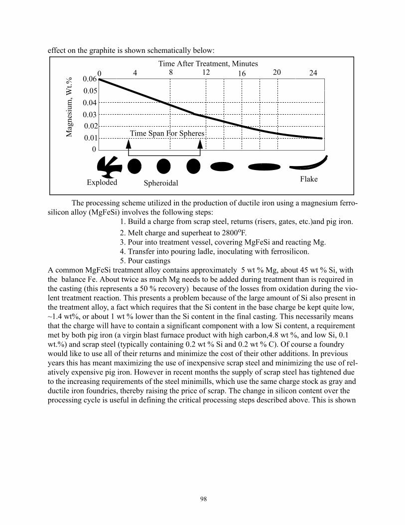
98
effect on the graphite is shown schematically below:
The processing scheme utilized in the production of ductile iron using a magnesium ferro-silicon alloy (MgFeSi) involves the following steps:
1. Build a charge from scrap steel, returns (risers, gates, etc.)and pig iron.2. Melt charge and superheat to 2800oF.3. Pour into treatment vessel, covering MgFeSi and reacting Mg.4. Transfer into pouring ladle, inoculating with ferrosilicon.5. Pour castings
A common MgFeSi treatment alloy contains approximately 5 wt % Mg, about 45 wt % Si, with the balance Fe. About twice as much Mg needs to be added during treatment than is required in the casting (this represents a 50 % recovery) because of the losses from oxidation during the vio-lent treatment reaction. This presents a problem because of the large amount of Si also present in the treatment alloy, a fact which requires that the Si content in the base charge be kept quite low, ~1.4 wt%, or about 1 wt % lower than the Si content in the final casting. This necessarily means that the charge will have to contain a significant component with a low Si content, a requirement met by both pig iron (a virgin blast furnace product with high carbon,4.8 wt %, and low Si, 0.1 wt.%) and scrap steel (typically containing 0.2 wt % Si and 0.2 wt % C). Of course a foundry would like to use all of their returns and minimize the cost of their other additions. In previous years this has meant maximizing the use of inexpensive scrap steel and minimizing the use of rel-atively expensive pig iron. However in recent months the supply of scrap steel has tightened due to the increasing requirements of the steel minimills, which use the same charge stock as gray and ductile iron foundries, thereby raising the price of scrap. The change in silicon content over the processing cycle is useful in defining the critical processing steps described above. This is shown
Mag
nesi
um, W
t.%Time After Treatment, Minutes
� ������������������������������������������������������������������������������������������������������������������������������������������������������������������������������������
� ������������������������������������������������������������������������������������������������������������������������������������������������������������������������������������ �����������������������������������������������������������������������������������������������������������������������������������������������������������������������������������
� �����������������������������������������������������������������������������������������������������������������������������������������������������������������������������������
� �����������������������������������������������������������������������������������������������������������������������������������������������������������������������������������
0.060.050.040.030.020.01
0
�
�
����������
�
�
����������
�
�
����������
�
�
����������
�
�
����������
��
��
��������������������
��
��
��������������������
��
��
��������������������
�
�
����������
�
�
����������
�
�
����������
�
�
����������
0 4 8 12 16 20 24
Exploded Spheroidal Flake
Time Span For Spheres

99
schematically below:
The objective is to produce an iron within the chemical specifications and having the required amount of Mg to create nodules. A mass balance is used to determine the charge makeup as well as the amounts of treatment and inoculant . The chemical composition of charge materials is given in Table 9.
Example Problem: We desire to produce a 200 pound heat of ductile iron in the MTU foundry with a compo-
sition of 3.6 C, 2.4 Si, and 0.04 Mg. We have the above charge and additive materials available. We know that the recovery of Mg during treatment in the tundish facility is about 50%. We also know that effective inoculation of ductile iron requires an addition of about 0.4% inoculant. This is more than is normally added to gray iron because the addition of Mg during treatment promotes the formation of eutectic carbide (Mg reduces the ∆T between graphite and carbide eutectics).
Determine the proper charge makeup, the amount of treatment and the amount of
Table 9: Chemical composition of Charge Components
Material Wt % C Wt % Si Wt % Mg Wt % Fe
Steel Scrap 0.2 0.2 0 99.6
Ductile Returns 3.7 2.4 0* 93.9
Pig Iron 4.2 0.2 0 95.6
Magnesium Treatment 0 45 5 50
Inoculant (Contains 1%Ca) 0 75 0 25
Ferrosilicon for charge 0 50 0 50
Graphite 100 0 0 0
* Magnesium in returns is lost on melting
Wei
ght P
erce
nt S
ilico
n
Time
� ��������������������������������������������������������������������������������������������������������������������������������������������������������������������������
�� ��������������������������������������������������������������������������������������������������������������������������������������������������������������������������
3
2
1
00
Charge
Treatment (Add MgFeSi to Nodularize Graphite)
Inoculation (Add FeSi to Nucleate Graphite)
Final Casting

100
inoculant needed to produce an iron with the correct composition.
Table 10:
Steps in procedure Logic and Calculations
Step 1.Determine the amount of inoculant needed.
a. 200 pounds x 0.004 = 0.8 pounds Inoculant
Step 2. Determine the amount of treatment material needed.
a. Because of the loss of 50 % of the Mg added, it is nec-essary to add twice as much.b. 200 pounds x 0.0008 = 0.16 pounds Mgc. This is provided by 0.16 / 0.05 = 3.2 pounds MgFeSi
Step 3. Determine the amount of silicon needed in the charge before treatment or inoculation.
a. A 200 pound heat with a final Si content of 2.4 wt % requires 200 x 0.024 = 4.8 pounds of Si.b. Steps 1 and 2 above give 0.8 x 0.75 (From inoculant) + 3.2 x 0.5 (From treatment) = 0.6 + 1.6 = 2.2 pounds Sic. Thus the initial charge needs 4.8 - 2.2 = 2.6 pounds Si.d. Thus the Si composition of the charge is 2.60 / 196 x 100 = 1.326 wt % Si
Step 4. Determine the charge makeup using as much returns and scrap steel as possible. The advan-tage of using scrap steel over pig iron is the cost. Usually scrap steel is much less expensive than pig iron, which is a virgin material.
a. Initially assume that the Si and C contents can be attained without using pig iron. Write three equations with three unknowns for the charge. Let X = weight of steel scrap , R = weight of returns, and G = weight of graphite (all in pounds) added to the initial charge. 1. X + R + G = 196 (200 minus treatment and inoculant) 2. X(0.002) + R(0.024) + G(0) = 2.652 (Si balance) 3. X(0.002) + R(0.037) + G(1) = 7.4 (C balance)b. Solve equations 1, 2, and 3 simultaneouslyThis gives : X = 89.56 pounds Scrap Steel R = 103.06 pounds Returns G = 3.38 pounds Graphite
Homework Problem: Develop a plan to specify the ongoing charge makeup at a minimum cost for producing the above grade of ductile cast iron subject to the following constraints: 1.Your foundry has the enviable experience of having an overall casting yield of 70%.
Thus,on average, only 30% of the iron units charged can come from returns. 2. Minimize the cost: The battle here is between fluctuating unit costs for scrap steel
(X$), pig iron (P$), foundry grade ferrosilicon (FS$), and graphite (G$). Obviously the unit cost for the returns is zero. Current costs can sometimes be obtained from the Metal Market News at the MTU library, or from operating foundries.
3. Carbon recovery by graphite additions is not 100%, but may be as low as 70%. 4. Optional homework.Look on as Extra Credit Goodie 5. Due: End of term by as many as three in a group. Four page limit, complete report.

101
Microstructures of Hypereutectic Ductile Cast IronsThe microstructures that evolve during casting of magnesium treated and properly inocu-
lated irons with CE > 4.3 are made up of graphite nodules surrounded by austenite. The scenario of events is best described with reference to the phase diagrams (stable and metastable) and a cooling curve which are shown below:
The sequence of events which likely occurs during the solidification of ductile cast iron is described with reference to the above diagram:
1. Nucleation of proeutectic spheres of Graphite 2. Growth of spheres with liquid composition following arrow A.3. As the temperature drops below TG, nucleation of austenite occurs onthe graphite and soon encloses the graphite in a shell of austenite. In addition conditions are good for the nucleation of austenite dendrites,whose subsequent rejection of carbon moves the liquidus compositionalong arrow B.4. Supersaturation of carbon in the liquid adjacent to the dendrites can provide conditions to allow more nucleation of new graphite nodules,which in turn can grow and be enveloped in austenite.5. Finally the solidification reaction is complete.
The sequence of events is illustrated schematically below:
Tem
pera
ture
Carbon Equivalent, CE
��
�
��������������������������������������������������������������������������������� �����������������������������������������������������������������������������������������������������
�������������������������������������������������������������
��
��
��������������������
4.3
���
������
������������������������������������
4.5
� ������������������������������������������������������������������������������������������������������������ ����������������������������������������������������������������
L
γ + LL + G
BarelyNoticeableGraphiteArrest
Nucleation ofGraphite Nucleiand Growth ofGraphiteSpheroids
Nucleation of Austeniteon Graphite Spheres andSimultaneous Nucleationand Growth of Austenite Dendrites
Fe3C Eutectic
A
B
TG
Time
1. 2. 3. 4.
Austenite Shell
Austenite Dendrite

102
Because of the surrounding of the graphite nodules with the austenite shell, this is not a typical eutectic reaction where both phases are simultaneously in contact with the liquid . Therefore this is sometimes called a neoeutectic, where growth of the graphite occurs by diffusion of carbon across the austenite shell into the graphite. The final as cast microstructure, of course, depends upon the combination of section size, alloy content, and processing history. Measurement made on the plane of polish to characterize these materials include:
1. Nodule Count - No. of nodules per square cm2. Nodularity - sphericity of nodules, described by aspect ratio of nodules.3. Matrix microstructure - ferrite, pearlite, ausferrite, combinations4. Extent of segregation and defects - carbides, inclusions,shrinkage, etc.
A typical as-cast microstructure consists of a bullseye structure of ferrite surrounding graphite which in turn is surrounded by pearlite. The development of this structure and relationship to a cooling curve is shown below:
������������������������������������������������������������������������������������������������������������������������������������������������������������������������������������������������������������������������������������������������������������
���������������������������������������������������������������������������������������������������������������������������������������������������������������������
��������������������������������������������������������������������������������������������������������������������������������������������������������������������������������������������������������������������������������������������������������������������
������������������������������������������������������������������������������������������������������������������������������������������
��������������������������������������������������������������������������������������������������������������������������������������������
������������������������������������������������������������������������������������������������������������������������
���������������������������������������������������������������������������������������������������������������������������������������
��������������������������������������������������������������������������������������������������������
� �����������������������������������������������������
������������������������������������������������������
��
����
��������������������������������������������������������������������������������������������������������������������������������������������������������������������������������
� �������������������������������������������������������������������������������������
TG
TF
TP
Austenite Grains
Graphite
���������������������������������������������������� ����������������������������������������������������������������������������������������������������������������
Ferrite Shell
����������������������������������������������������
��
����
���������������������������������������������������������������������������������������������������������������������������������������������������������������������������������������������������������������������������������������������������������������������������������������������������������������������������������������������������������������������������������������������������������������������������������������������������������������������������������������������������������������������������������������������������������������������������������������������������������������������������������������������������������������������������
��������������������������������������������������
��
��
������������������������������������������������������������������������������������������������������������������������������������������������������������������������������������������������������������������������������������������
Pearlite
Neo-eutectic Reactionforming graphite &austenite
Ferrite begins to formon graphite (carbon “sinks”)
Casting cooling rapidlyenough that diffusion ofcarbon through the ferriteshell cannot keep pace withthe wishes of the phase diagram and so pearlite hasan opportunity to nucleate and grow into the remaining austenite.The “bullseye” structure is formed.
BULLSEYESTRUCTURE
Graphite Liquidus
Graphite nodulesforming & growing
[Resulting from graingrowth to mask evidenceof original dendritesand austenite shells]
Ferrite FormationUpper Critical Temp
Pearlite Reaction Temp
Reaction progresses bydiffusion of C throughferrite.
“Colonies”

103
The relative amount of ferrite present depends upon alloy content, nodule count, and the rate at which the casting is cooled through the transformation where ferrite and pearlite can form and grow, i.e. the same factors as those promoting ferrite in gray cast iron. Alloying of Cast Irons
The primary purpose of alloying cast irons is to control the matrix microstructure, which usually means to control the identity of the austenite transformation product. Addition of alloying elements to cast irons (the Fe - C - Si system) has a measurable effect upon both the thermody-namics of the system (i.e. the position of stable and metastable phase boundaries) and upon the kinetics of a transformation (which usually has something to do with the rate at which carbon can move in the system). Austenite transformation products include;
The particular austenite transformation product or products observed will depend upon the section size of the casting, the size of the graphite flakes (surface area per unit volume), and the manner in which the casting was cooled (i.e. continuously cooled or isothermally reacted) in addition to the amount and type of alloying elements that are present. The microstructural results of continuous cooling are best described by the continuous cooling diagram (CCT) for a given cast iron, a sche-matic of which is illustrated in the attached figure below.
Cooling curves passing through the specific transformation product regions (TPR) in temperature
Austenite (γ, fcc) ->
Ferrite( α , bcc) + GraphiteFerrite + Graphite + Pearlite( α + Fe 3C)PearlitePearlite + Ausferrite( γ + α )AusferriteAusferrite + Martensite( α ’)Martensite
ContinuousCooling
Isothermal
or
Schematic CCT diagram for a cast iron illustrating Log Time (t)
Pearlite
Ferrite + Graphite
Ausferrite
Martensite
Stable Austenite + Graphite
Unstable
Upper Critical Temperature
Martensite Start
Martensite Finish
Austenite
F + P
F + P + AA + MM
the presence of TPR of Ferrite, Pearlite, Ausferrite, and Martensite in T - t space

104
- time (T - t) space in the above figure illustrate a variety of microstructures depending upon the cooling rate. The slowest cooling specimen (largest section size) passed through the TPR of Fer-rite + Pearlite (F + P). As the cooling rate increases the transformation products change as shown until the product for the highest cooling rate is 100% martensite (M).
The shape of the various TPR and their position in the CCT diagram illustrated above will depend most strongly upon the chemical composition of the austenite which is transforming. Of course, the matrix austenite carbon content is an important variable which will in turn depend upon the identity and amount of the other alloying elements present.
The position in temperature - time space of the TPR within CCT diagrams for the transfor-mation of austenite in steel is determined primarily by the composition and the austenite grain size. Thus the so-called hardenability of steels is primarily dependent upon the alloy content, the carbon content and the austenite grain size.
This dependence of the TPR in T - t space on carbon content, alloy content and austenite grain size is also true for gray and ductile cast irons. However a complicating factor for cast irons results from the presence of graphite and the variability of matrix carbon content with temperature in equilibrium with that graphite. Thus very fine D and E type graphites in gray cast irons (and the high nodule count irons characteristic of well inoculated ductile irons), with their much higher surface area per unit volume on which nucleation of ferrite can occur, would be expected to have more ferrite present than an iron in which the graphite were present as the larger, more random A-type flakes; i.e. the ferrite + graphite TPR in the above figure would be shifted to shorter times. The nucleation and growth of ferrite is the only transformation product shown in which requires the presence of graphite, the growing ferrite resulting from relatively long range diffusion of car-bon to graphite flakes. The other diffusional products (P, A) have the same composition as the matrix austenite and therefore require only short range carbon diffusion (interlamellar spacings in pearlite and the small space between the acicular plates of ferrite in ausferrite)to grow, depending for nucleation upon the presence of surfaces (austenite grain boundaries, graphite surfaces, ferrite boundaries, etc.). Martensite formation requires no diffusion, only requiring surfaces upon which to nucleate.
In addition to their effect upon hardenability (position of the TPR in T-t space) substitu-tional alloy additions (Cu, Ni, Mo, Mn, Cr, etc) will have an important effect upon the final mechanical properties as a result of where they finally reside within the cast microstructure. An overview of the details of the effects of alloying elements in gray cast iron can be found in the lit-erature (1 Angus, 2 Iron Castings Handbook, 3 ASM “Cast Irons”).
Mechanical Properties of Ductile Cast Iron
The mechanical properties of ductile cast iron are significantly different than that of gray iron because of the difference in shape between the graphites in these cast irons. In ductile irons the matrix is the continuous entity so that there are no easy crack paths to propagate fracture. As a result, ductile cast irons have significant ductility and toughness, properties which place this unique material in competition with other ferrous materials such as cast steels, forged steels, and even wrought steels. Tensile Properties
As a result of the continuity of the matrix, the tensile properties of ductile cast iron depend almost completely upon the microstructure of the matrix, a microstructure which can be con-

105
trolled by heat treatment. An overview of the tensile properties of ductile iron is given below:
As-Cast and Quenched and Tempered Grades of Ductile IronThe Ultimate Tensile Strength vs. % Elongation diagram above illustrates the large range
of properties available in the as - cast and quenched and tempered conditions. These grades are represented with solid circles and the series of numbers representing the UTS-YS-%EL for each grade. It can be seen that grade 60-40-18, with the most ductility (highest %EL), corresponds to an iron with a 100% ferritic (indicated with an F) matrix. As the amount of pearlite (indicated with a P) increases, the strength increases with a corresponding decrease in %EL, until grade 100-70-3 is reached which is 100% pearlite. Grades in between ferritic and pearlitic have pearlite and ferrite present in different proportions. The four as-cast grades shown are utilized in specifications as minimums for design purposes. The actual grade achieved will depend upon alloy content and
��
��
��������������������������������������������������������
Percent Elongation
Ulti
mat
e Te
nsile
Stre
ngth
(ksi
)
��
����
��������������������������������������������������������������������������������������������������������������������������������������������������������������������������������������������������������������������������������������������������������������������������������������������������������������������������������������������������������������������������������������
� ���������������������������������������������������������������������������������������������������������������������������������������������������������������������������������������������
� ���������������������������������������������������������������������������������������������������������������������������������������������������������������������������������������������
� ���������������������������������������������������������������������������������������������������������������������������������������������������������������������������������������������
� ��������������������������������������������������������������������������������������������������������������������������������������������������������������������������������������������
� ���������������������������������������������������������������������������������������������������������������������������������������������������������������������������������������������
� ��������������������������������������������������������������������������������������������������������������������������������������������������������������������������������������������200
180
160
140
120
100
80
60
40
�
�
����������������������������
�
�
����������������������������
��
��
��������������������������������������������������������
�
�
����������������������������
�
�
����������������������������
�
�
����������������������������
�
�
����������������������������
�
�
����������������������������
0 10 202 4 6 8 12 14 16 18
F
60-40-1865-45-12
80-55-6
TM = TemperedMartensite
P = PearliteF = FerriteADI = Austermpered
Ductile Iron
ADI
ASTMGrades of ADI
1
2
3
4
(Guaranteed Minimums) xx-yy-zz(Grade)_
UTS YS %EL(Guaranteed Minimums)TM
120-90-2P
100-70-3P+F
F+P�� ��������������������������������������������������������������������������������������������������������������������������������������������������������������������������������������������
UTS v. % Elongation -Summary of Common As-Cast and Austempered Grades of Ductile Iron

106
section size. The grade 120-90-2 is a heat treated grade in which the iron has been austenitized,
quenched to martensite and tempered. Typical chemical compositions for these irons are given in Table 11. There are no chemical specifications for a specific grade. Each foundry and casting application will determine the combination needed to obtain the minimum mechanical property specifications. It will be noted in the above table that the ferritic grades contain a minimum of the alloy elements Cu and Mn, both of which promote the formation of pearllite when the casting is cooling. On the other hand the grades with pearlite commonly have a specification with a mini-mum of copper. The elements Mn and Cr come from the steel component of the charge; these are both common and important elements in the production of steel. Many ferritic matrix castings are obtained by annealing, a heat treatment where the casting is austenitized and then slowly cooled, giving a large amount of time for the formation of ferrite. This heat treatment, of course, adds sig-nificantly to the cost of production and is not usually desired. Low residuals of Mn and Cr can be achieved by melting larger quantities of pig iron, a charge material which is usually more expen-sive than scrap steel.Austempered Ductile Cast Iron
All of the as-cast grades of ductile iron as well as the quenched and tempered grade have the same body centered cubic (bcc) matrix. The differences in hardness and tensile properties shown on the figure on page 105 are due to the differences in the distribution, shape and size of the iron carbide particles within that matrix. Of course the softest matrix (ferrite)has no carbides, while the lamellar carbides produced in pearlite contribute to an ever increasing hardness. The hardest matrix is achieved by the tempered martensite where the carbides are very tiny indeed. The shaded region which includes the as-cast grades represents the range of tensile properties attainable with ductile iron with a body centered cubic (ferrite) matrix.
In recent years the grade of ductile iron known as austempered ductile iron (ADI) has been developed, a grade of iron in which heat treatment is utilized to produce a metastable face centered cubic matrix, austenite, which is stable at room temperature. It can be seen from the fig-ure on page 105 that the ASTM grades of ADI are shifted to considerably higher strengths than
Table 11: Typical Chemical Compositions(Wt Percent), Matrix Micro, BHN
Element Grade60-40-18
Grade65-45-12
Grade80-55-6
Grade100-70-3
Grade120-90-2
Carbon 3.5 - 3.9 3.5 - 3.9 3.5 - 3.9 3.5 - 3.8 3.5 - 3.8
Silicon 2.2 - 3.0 2.5 - 2.8 2.2 - 2.7 2.2 - 2.7 2.2 - 2.7
Manganese 0.30 max 0.40 max 0.2 - 0.5 0.6 max 0.6 max
Chromium 0.06 max 0.10 max 0.10 max 0.10 max 0.10 max
Copper - - 0.2 - 0.4 0.2 - 0.5 0.2 - 0.5
Microstruc-ture
Ferrite Mostly Ferrite
MostlyPearlite
Pearlite Tempered Martensite
BrinellHardness
130 - 170 150 - 220 170 - 250 241 - 300 270 - 550

107
the as-cast grades, yet retaining excellent ductility. The primary cause of this dramatic improve-ment in mechanical properties stems from the presence of the face centered cubic matrix together with a fine scale dispersion of ferrite. The ASTM grades represent guaranteed minimums in ten-sile strength and ductility; the cross hatched region located to higher strengths and ductilities from the ASTM grades represents more typical ADI. Clearly ADI offers an entire new opportunity for applications of ductile cast iron. Indeed ADI, with comparable strengths and ductilities, is making inroads into markets once dominated by steel forgings and steel castings. The Metastable Phase Diagram and Stabilized Austenite
The concept of austempered ductile iron with an austenitic matrix can be understood with reference to a portion of the metastable Fe - C - 2.4 Si phase diagram schematic shown below:
This diagram shows the low temperature portion of the Fe - C - 2.4 Si isopleth. The amount of 2.4 Si was chosen to correspond to a typical ductile cast iron. Note that the metastable Fe - Fe3C dia-gram is not a part of this diagram but that other features are present, including the martensite start temperature (that temperature below which austenite must be quenched to obtain the hard, brittle, body centered tetragonal martensite phase), and the metastable extension of the α + γ / γ phase boundary. These features are necessary to understand the presence of austenite at room temperature which is stable. Consider now the heat treatment which is used to produce austempered ductile iron.
1. Casting is heated into the austenite + graphite field and held at Tγ until fully austen-itized. At this point the structure consists of austenite of 0.8 wt. % C and graphite nodules.
2. Cool rapidly to TA, the austempering temperature and hold, allowing the reaction:γ (0.8 C) -> α (0 C) + γ (2.0 C) [AUSFERRITE]
�
�
���������������������������������������
Tem
pera
ture
(Ko )
γ
α +γ
��
��
��������������������������������������������������
� ������������������������������������������������������������������������������������������������������������������������������������������������������������������Τγ
� ����������������������������������������������������������������������������������
�
�
������������������
��
�
������������������������������������������������������������������������������������������������������������������������������������������������������������������������������������������������������������������������������������������������������������������������������������������������������������������������������������������������������������������������������������������������������������������������������������������������������������������������������������������������������������������������������������������������������������������������������������������������������������������������������������������������������������������������������������������������������������������������������������������������������������������������������������������������������������������������������������������������������������������������������������������������������������������������������������������������������������������������
α + γ
�
�
�����������
Wt. Percent Carbon2
γ + Graphite
0
Martensite Start, MS
Metastable γ / α + γ Phase BoundaryΤΑ
3.6
�������������������������������������������������������������������������������������������������������������������������������������������������������������������������������������������������������������������
���������������������������������������������������������������������������������������������������
���������������������������������������������������������������������������������������������������������������������������������������������������
������
� ���������������������������������������������������������������������������������������������������������������������������������������������������������������������������������������������������������Room Temperature
0.8
α
α + Graphite

108
This reaction usually requires about 1 - 2 hours to complete and gives a structure shownschematically below.
In a piece of steel heat treated the same way, the austenite would transform to bainite, atwo phase mixture of ferrite and iron carbide (Fe3C). However, in cast irons, the presence of silicon prevents the formation of carbides initially. The system takes the path of leastresistance and obeys (once again) the metastable phase diagram.3. If given enough time the austenite will eventually transform to bainite. However, before
that happens the casting will be cooled to room temperature, a move which will retain the struc-ture created at TA. The austempering reaction is said to have “stabilized” the austenite. By virtue of the high carbon present in the ausferrite (reflecting the absence of carbon from the ferrite), the martensite start temperature has been reduced to near absolute zero degrees Kelvin (see the dia-gram on page 104). The martensite start temperature is a very strong function of carbon content. Since the carbon must be retained in the martensite in this diffusionless transformation and it tends to want to expand the lattice, more driving force (undercooling) becomes necessary as car-bon content increases. Therefore as the austenite becomes richer in carbon during the ausferrite reaction it becomes stabilized to the notion of transforming to martensite. This allows cast irons to be austenitic at room temperature, an accomplishment made in commercial grades of steel only by adding large quantities of nickel or manganese. Of course, this is what makes ADI a unique mate-rial and what gives it the remarkable properties shown in the diagram on page 105.
There are a number of problems associated with the production of ADI, problems which are concerned first with the production of a quality grade of ductile cast iron, and secondly with the control of the heat treatment parameters necessary to convert austenite to ausferrite. It goes without saying that the heat treated product cannot overcome basic deficiencies in the cast state.A list of these “deficiencies” includes porosity (shrinkage and gas), slag, sand, inclusions from impurities, low nodularity, low nodule count, etc. All of these extrinsic deficiencies can be mini-mized by good foundry practice and adhering to tight processing schedules, i.e. control of all temperatures in the sequence, establishing a rigorous schedule for treatment, inoculation, and pouring the castings. Some “deficiencies” that cannot be overcome are intrinsic to the process of solidification, including microsegregation in the casting and limitations in the nodule count that is attainable, a limitation defined primarily by the cooling rate (section size) of the casting. It is true that inoculation can increase nodule count, but not usually beyond a maximum for the given sec-tion size and mold type. Microsegregation is in principle capable of being eliminated by a homog-enization step, where the casting is brought to a temperature close to its melting point and soaked at the high temperature until solid state diffusion has eliminated the problem. Unfortunately homogenization processes are very expensive and while it is cost effective for some materials it is
�������������������������������������������������
��
����
����������������������������������������������������������
Before Reaction After Reaction
Graphite Nodules + γ (0.8 C) grains Graphite Nodules + α (0 C) + γ (2 C)
Austempering
1 - 2 Hours at TA

109
just not a practical thing to do with cast irons . It is then necessary to live with the intrinsic defi-ciencies and adjust the heat treating parameters to accomodate any problems that may arise as a result.Austempering Ductile Iron and the Isothermal Transformation Diagram
A grasp of the important parameters defining the process in heat treating these materials requires a basic understanding of the isothermal transformation diagram that describes what is necessary to produce ADI successfully, and also what is necessary to avoid so that the desired structure is attained. A schematic ITT diagram is given below for a ductile cast iron which is
being austenitized at Tγ and austempered at TA. There are four steps in the heat treatment scheme which are numbered on the ITT diagram.These four steps and the considerations associated with each are given below:
Step (1) - Austenitize for a time so that the matrix is completely austenite with a fairly homogeneous carbon composition. A rule of thumb for time is one hour per inch of section, with allowance for heat up time as well. The temperature selected will depend upon the alloy composi-ton; it is necessary that the so-called upper critical temperature be exceeded, that temperature below which ferrite is a stable phase.
Step (2) - Cool to the austempering temperature at a rate sufficient to “miss the Pearlite Nose” on the ITT diagram. This is most often accomplished in salt baths so that the rate of heat transfer is maximized. In heavier section castings it is necessary to alloy them quite heavily (usu-ally with various combinations of Cu, Ni, and Mo); this has the effect of moving the entire ITT
����������������������������������������������������������������������������������������������������������������������������������������������������������������������������������������������������������������������������������������������������������������������������������������������������������������������������������������������������������������������������������������������������������������������������������������������������������������������������������������������������������
� ��������������������������������������������������������������������������������������������������������������������������������������������������������������������������������������������������Upper Critical TemperatureTγ
Tem
pera
ture
Time
TA
��
��
������������������������������������������������������
��
����������������������������������������������������������������������������������������������������������������������������������������������������������������������������
������������������������������������������������������
�������������������������������������������������������������������������������������������
����������
��
��
����������������������������������������������������������������������������������������������������������������������������������������������������������������������������������������������������������������������������������������������������������������������������������������
Pearlite (α + Fe3C)
Bainite (α + Fe3C)
Ausferrite(α + γ)
Austenitize (1) Cool to TA (2)
Hold at TAAustemper (3)
Cool to Room Temperature (4)
PearliteNose
1%99%
Isothermal Transformation Diagram for a Hypothetical Ductile Iron

110
diagram to greater times thereby allowing the cooling from Tγ to TA without generating pearlite within the casting.
Step (3) - Hold at the Austempering Temperature for a time until the ausferrite reaction [γ (0.8 C) -> α (0 C) + γ (2 C)] is complete, but not so long a time that the bainite reaction[ γ (2 C) -> α (0 C) + Fe3C] occurs. The time is selected using a combination of information including primarily alloy content and austenitizing temperature. Obviously it would be helpful to have ITT diagram information for each alloy produced.The diagram defines the beginning of the ausferrite reaction with a note indicating that the reaction has progressed 1 %, and similarly the end of the reaction with a note at 99% transformed.
Step (4) - Cool to room temperature for shipment to the customer. It is not necessary to cool rapidly; rather the castings are allowed to cool uniformly so as to minimize any residual stresses which could arise were castings to cool nonuniformly.
It is important that the above steps be carried out in a consistent manner time after time, so that quality ADI is produced time after time.Control of Mechanical Properties of ADI
The four ASTM grades of ADI illustrated on page 102 can in principle be created from the same cast alloy. The major factor controlling these tensile properties in ADI which has been pro-duced from quality ductile iron and heat treated in a quality manner is the choice of the austem-pering temperature. This parameter is primarily responsible for defining the scale of the ausferrite product, where the term scale refers to the size and number of the ferrite particles in the austenite matrix. It is generally true that high austempering temperatures give course microstructures with relatively low strengths but higher ductility. On the other hand low austempering temperatures give very fine microstructures with high strengths but lower ductility. High austempering temper-atures are in the range 400 - 425 oC giving ASTM grade 1 ADI,while low austempering tempera-tures are in the range 275 - 300oC giving ASTM grade 4 ADI.
Examples of potential applications for ADI include gears, automotive crankshafts, digger teeth for front end loader applications, automotive camshafts, railroad car wheels, etc. Many applications require resistance to sliding wear, a property enhanced by the presence of the austen-ite which transforms to martensite in service.
Compacted Graphite Irons, Production and PropertiesCompacted graphite irons (CG) are the newest form of cast iron, recognized since 1965
(R. D. Schelleng, Cast Iron (with vermicular graphite) US Patent 3,421,886, May 1965) as having

111
unique mechanical and physical properties determined in large part by the shape of the graphite. These irons are produced in much the same way as ductile cast iron, except the objective is to have the molten iron dissolve a lesser amount of Mg, usually ~ 0.01 - 0.015 Wt. %. This amount of Mg is enough to guarantee that no flakes are formed, yet not high enough to allow full nodular-ity . A typical CG iron might contain 25% nodularity, the rest of the graphite having a twisted rod-shaped structure. The mechanical and physical properties of compacted graphite irons, for a given matrix microstructure, will reside in between the properties of flake graphite irons and spheroidal grahite irons as shown schematically below. .
Malleable Cast IronAs indicated previously, malleable cast iron is a material with lower carbon (2.0 - 2.6) and
lower silicon (1.1 - 1.6) than gray cast iron, and solidifies as white cast iron. These are hypoeutec-tic irons which solidify by first forming austenite dendrites and then the eutectic austenite + cementite (Fe3C). The cast structure is then heat treated to produce the popcorn-type graphite structures that are characteristic of malleable cast iron. The phase diagram and the cooling curve
���������������������������������������������������������
��������������������������������
Duc
tility
Low
High
Percent Nodularity0 100
Ther
mal
Con
duct
ivity
Dam
ping
Cap
acity
High
Low
Stre
ngth
���
������
���������������������������
���
���
����������������������������������������������������������������������������������������������������������������������������������������������������������������������������������������������������������������������������������������������������������������������������������������������������������������������������������������������������������������������������������������������������������������������������������������������������������������������������������������������������������������������������������������������������������������������������������������������������������������������������������������������������������������������������������������������������������������������������������������������������������������������������������������������������������������������������������������������������������������������������������������������������������������������������������������������������������������������������������������������������������������������������������������������������������������������������������������������������������������������������������������������������������������������������������������������������������������������������������������������������������������������������������������������������������������������������������������������������������������������������������������������������������������������������������������������������������������������������������������������������������������������������������������������������������������������������������������������������������������������������������������������������������������������������������������������������������������������������������������������������������������������������������������������������������������
�
�
����������������
80%
DuctileIrons
CGIrons

112
characteristic of white cast iron is given below:
It can be seen in the cooling curve that the temperature has reached TC before nucleation of graph-ite has occurred thus resulting in the eutectic austenite plus carbide formation. The low silicon content, 1.5, and low carbon, 2.3, results in a smaller ∆T than for gray or ductile cast iron thus promoting the formation of white iron. After the casting has cooled to room temperature, the heat treatment to produce solid state formation of graphite, and therefore the popcorn graphite struc-ture of malleable iron begins and is illustrated below. The castings are heated slowly into the γ +
Fe3C two phase field to a temperature TSSG where it is soaked for as long as 24 hours. During this soaking time graphite will nucleate on the eutectic carbide particle surfaces and grow at their expense. Eventually all of the carbide will be replaced by “popcorn” graphite and the structure left behind will be quite similar to ductile cast iron except for the shape of the graphite. Like ductile cast iron the matrix is the continuous phase and so the final structure will have similar prop-erties to ductile cast iron, excellent strength, ductility and toughness. The strength and ductil-ity of malleable irons would overlap the as-cast properties of ductile iron shown on page 105.
Tem
pera
ture
���������������������������������������������
Liquid, L
γ + Gr
γ
α+γ
α + Gr
α
γ + L
α + γ + Gr
L + Gr
����
��
����������������������������������������
�� �������������������� ���������������������������������������������������������������������������������������
�� �����������������������������������
���������������������������������������������������������������������������������������������������
�
���������������������������������������������������������������������������������������������������������������������������������������������������������������������������������������������������������������������������������������
���
���������
���������
���������������������������������������������
� ����������������������������������������������������������������������������������������������������������������������������
��
��������������������������������������������������������������������������������������������������������������������������������������������������������������������������������������������������������������������������������������������������������������������������������������
�
�
������������������������������������������������
�
��
����������������������������������
Fe3C
(γ + Fe3C)
(α + γ + Fe3C)
(α + Fe3C)
L + Fe3C∆Τ
Carbon Equivalent, CETime
Cooling Curve
TL
TGTC
TL = γ Liquidus
TG = Graphite Eutectic
TC = Carbide Eutectic
SolidificationComplete
2.8
(White Iron)
� ����������������������������������������������������TSSG
TUC
Time
Tem
pera
ture
�� ���������������������������������������������������������������������������������������������������������������������������������������������������������������������������������������������������������������TSSG
���
���
���������������������������������������������������������������������������������������������������������������������������������������������������������������������������������������������������
Slow HeatingNucleates Many
Graphite ParticlesTR
Soaking at TSSG allows Growth of
Graphite Particles at Expense of Carbide Ferritic Malleable
Pearlitic
�
�
�������
24 hours Malleable
� �����������������������������������TUC

113
Pearlitic malleable irons would be stronger but less ductile than ferritic malleable cast irons for the same reasons as for ductile iron. The temperature - time diagram on the previous page illus-trates the heat treatments responsible for the production of ferritic malleable iron (by slow cool-ing through the upper critical temperature, TUC) and pearlitic malleable iron (by more rapid cooling, even cooling in air) after the malleablizing treatment.
Malleable cast iron has been produced by human beings for thousands of yesrs, but it is slowly but surely being replaced by ductile cast iron. Two important reasons why malleable iron is decreasing in favor, is cost and limitations on section size that can be produced in the mal-leable state. Clearly it is less costly to produce nodules in the as-cast condition than to require an additional long time heat treatment step. In addition ductile cast iron can be produced in very large section sizes, while the requirement to start with white iron limits malleable to practical sec-tion sizes on the order of 1 - 2 inches. Malleable iron section sizes larger than this will solidify with graphite flakes and would therefore have severely reduced ductility. A comparison of the United States’ production of malleable, ductile, and gray cast irons in the figure below illustrates the unmistakable trends. Malleable iron is a dying breed, and most of its former applications have been replaced by ductile cast iron.
The data in this plot shows scatter which is a result of fundamental change (decreasing gray and malleable iron and increasing ductile iron production) as well as a reflection on the economics of the times.It is interesting to note the dip in production of all three of these materials in 1982, a recession which hit the casting and manufacturing industry very hard. Indeed the production of steel in the U.S. plummeted from ~ 140 million tons in 1980 to about 80 million tons in 1982.
� �����������������������������������������������������������������������������������������������������������������������������������������������������������������������������������
� ������������������������������������������������������������������������������������������������������������������������������������������������������������������������������������
� ������������������������������������������������������������������������������������������������������������������������������������������������������������������������������������
�
����������������
�
�
����������������
�
�
����������������
�
�
����������������
��
��
��������������������������������
�
�
����������������
�
�
����������������
�
�
����������������
�
�
����������������
�
�
����������������
�
�
�����������������
�
�
����������������
��
��
��������������������������������
�
�
����������������
�
�
����������������
�
�
����������������
1970 1980 1990 2000Year
Prod
uctio
n (M
illio
ns o
f Ton
s)
12
10
8
6
4
2
0� ������������������������������������������������������������������������������������������������������������������������������������������������������������������������������������
���������������������������������������������������������������������������������������������������������������������������������������������������������������������������������������������������������������������������������������������������������������������������������������������������������������������������������������������������������������������������������������������������������������������������������������������������������������������������������������������������������������������������������������������������������������������������������������������������������������������������������������������������������������������������������������������������������������������������������������������������������������������������������������������������������������������������������������������������������������������������������������������������������������������������������������������������������������������������������������������������������������������������������������������������������������������������������������������������������������������������������������
��������������������������� ����������
Gray &Ductile
1.2
1.0
0.8
0.6
0.4
0.2
0
MalleableRecession
Projected
Ductile IronGray IronMalleable Iron
Data from Modern Casting

114
XV. Defects in Cast MetalsGases in Metals
Sources - Gases dissolved in liquid; Gases from mold or core material
1. Gases dissolved in the metal - Classic example of Hydrogen in Aluminum Alloys
From the schematic plot below there is a much greater solubility of H in the liquid than the solid.
Thus, if the gas is present in the liquid, hydrogen will be evolved as H2 during solidification. This gas may be trapped in the casting which results in porosity or “blows”.
Sources of H : H2O in air, charge; H - containing compounds in combustion gases; contaminationof the charge with oil,grease,etc.Remedy- Bubble a gas through the melt, like argon, nitrogen, chlorine, sulfur hexafluoride. These gases cleanse the melt by action of Sievert’s Law and by providing a reactant with which the hydrogen can be chemically changed and then removed.
Sievert’s Law- % H = Kp(H2)0.5
In this expression H is the concentration in liquid Al , K is the equilibrium constant, and p(H2) is the partial pressure of H in equilibrium with a gas in contact with the melt. If new gas with low p(H2) is continually added the H will be extracted from the melt to establish equilibrium. Thus H will be eliminated before pouring the casting. This mechanism will work well with an inert gas like argon; however a more potent method will include using a gas containing a reactive compo-nent like chlorine or SF6. In this situation the H reacts with the Cl or the SF6 and is removed as another gaseous species, for example HCl . Unfortunately this is a rather dangerous product and most aluminum foundries are working hard to eliminate the use of Cl. The gas used in our experi-mental foundry is argon with about 5% SF6.2. Gases from molds or cores
Binder systems for cores or molds create gaseous combustion products when encountering the heat from the casting operation. These gases must be vented from the mold, otherwise “blows” can be produced in the casting. Venting is accomplished by suitable holes being placed in the
Temperature
%H
Tmp
liquid
solid 0.5 ml/100 g Al

115
cores or molds. Gases that find their way into castings are often trapped under the cope surface, but can actually be found anywhere within the casting depending upon the situation.Remedy - Proper venting, reduce binder content in core, change binder in core, increase sand per-meability, control pouring temperature, etc.
Controlled Positive Effects of Gas in Castings
1. Al alloys - Add potatoes to the melt to increase the gas content; finely divided H2 porosity may be preferred to large macroshrink porosity - this technique is usually not recommended.
Hot TearsHot tears are defects which occur most often in materials with a large range of solidifica-
tion and with significant mold constraints. Hot tears are defects which require the presence of a liquid. Consider the phase diagram and sand casting below:
Alloys with compositions between 0 and c0 wt. fraction B and between c1 and 1 will, on cooling from the liquid, pass through the shaded regions in the α + L and L + β two phase fields. Within these shaded regions these alloys will experience a temperature range over which more than 50 % solid is present. For example an alloy of composition cA will have about 50 % solid α at TA, and on cooling to TE this solid amount will increase by the lever rule to about 70 %. Thus it is antici-pated that solid continuity will exist throughout the surface volume of the piece over a temper-ature range in which contraction of that solid due to cooling is occurring in the presence of the liquid. Solid continuity is expected along the surface because that is where solidification usually begins. If the contracting solid is constrained by a rigid or even an expanding mold, stresses may build up within the solid portion of the casting which are ultimately relieved by tensile failure along some convenient dendrite - liquid interface. The casting is literally torn apart. This failure is known as a “hot tear”, an opening which may or may not be filled by the liquid that is present.
Consider the tensile bar shaped casting shown above, a sand casting with an alloy concen-tration of cA which in the sketch is shown as being partly solidified in the temperature range TA to
L
α βα + L L + β
α + β
0 1Weight Fraction B
�
�
�������
�
�
�������
c0 c1
��
��
��������������������������
cA
������������������������
Tem
pera
ture TA
Solidifying MetalLiquid Metal
Hot Spots
Tensile Bar Shaped Casting
TE� �������

116
TE. The solidified metal is shown as being continuous on the surface of the casting, with rela-tively thick solid layers at the external corners (large mold volume to extract heat) and thin solid layers at the internal corners (the so-called hot-spots where there is only a small mold volume to extract heat). The continuity of the solid combined with the reality of this continuity over the tem-perature range TA - TE results in the weak solid skin wanting to contract. At the same time the mold is heating and it wants to expand. The clash between the expanding mold and the contract-ing solid metal will generate tensile stresses in the solid metal and compressive stresses in the mold. It is apparent that something will have to give. If the mold remains rigid and expanding it is inevitable that the solid skin of the casting will “tear” at the weakest points in the system, the hot spots shown on the above sketch. These tears often will extend to the surface resulting in what appears to be cracks. The presence of the liquid during this event may allow the hot tear to be filled as it is happening. In this case the integrity of the casting will not be lost but it is possible that the liquid “filler” , because of segregation, could have a significantly different composition than the solid and thus act as a weak point in the structure. If, on the other hand, the liquid cannot fill the expanding tear, then the integrity of the casting is lost.
The likelihood of such an occurrence:1. Increases as the temperature range containing more than 50% solid increases. Thus the problem is minimized for pure elements and eutectics.2. Increases as sand expansion increases. Thus collapsible sand molds are helpful to avoid the production of tensile stresses in castings. Molding sands with minimal thermal expansion will also tend to minimize this defect.3. Increases in designs containing coring (particularly with large cores) and casting designs containing sharp corners or large section size changes.
Remedies:1. If possible, stay away from specifying large freezing range alloys for castings. Of course this is not always possible, and so the designer must be aware of the problem and take other steps to minimize the problem.2. If possible, use generous fillets in design to avoid hot spots (see the examples below) and minimize section size changes.
3. If possible, make additives (cereal, wood flour) to sand to improve collapsibility. These additives, which are part of the binder, will combust in service near the mold-metal interface, destroying the bond and making the sand more collapsible, thereby relieving the compressive stresses in the sand.
Not This This

117
Other Significant Commercial Areas where Hot Tearing is a Potential Problem1. Brazing, soldering and welding materials where large and rapid expansion-contraction-situations occur. The solution most often used in such situations is to select eutectic or near eutectic materials as filler metals (which solidify over a small temperature range where there are no opportunities for continuous solids to exist over a temperature range), thereby minimizing the problem.2. Continuously cast slabs and billets of steel which experience rapid changes in cooling during the casting operation often generate hot tears which are subsequently filled in with a liquid experiencing macrosegregation. Unlike microsegregation, which is a local prob-lem on the order of dendrite arm spacing, macrosegregation can result in large changes in composition from one point to another in the casting. Thus even though the hot tears are filled in with liquid, the macrosegregated liquid “tears” result in planes of weakness which can easily fail in subsequent rolling operations.
Residual Stresses in CastingsResidual stresses are elastic stresses remaining in a casting which result from variations in
cooling rate from point to point as the casting cools to room temperature. These stresses are developed in the solid state and have nothing to do with solidification. If the developing stresses are large enough and exceed the elastic limit, cracking or warping of the casting can occur before the casting reaches room temperature. Consider, for example, an automobile disc brake rotor. Rotors are usually gray iron castings which are typically a class 30 iron, with a pearlitic matrix as cast. A schematic of a rotor showing a cross section is given below together with cool-ing curves from thermocouples placed within the hat (point 1) and the inboard wear plate (Point 2). Stress distributions within the wear plate are also illustrated for two times in the cooling

118
sequence.
Recrystallization Temperature, Plastic - Elastic TransitionIn the above sketch it is important to note that the “hat” section of the rotor has a larger
cross section (typically 3/4 in. vs. 1/2 in.) than either the inboard or outboard wear plates (The wear plates are the surfaces on which the brake pads ride.). The cooling curves in the sketch reflect that difference, the hat section cooling at a much slower rate than the wear plate. As a result of the section size difference the cooling curve for the hat section crosses the temperature of one half of the melting point,Tm/2, at a later time than the wear plate; i.e. tH > tI. One half of the melting point is commonly used as an estimate of the recrystallization temperature of a metal material, the temperature which separates plastic flow (where dynamic recrystallization can take place) from the lower temperature regime in which significant elastic deformation occurs. The result of these different parts of this casting cooling to room temperaure at different rates finally generates the residual elastic compressive stresses (tangential) and tensile stresses (radial) in the wear plates as shown in the above figure. The cooling curve - developing stress scenario is out-lined below:
1. At time t0, just after solidification is complete, both the hat and the wear plate sections are cooling and contracting, but at different rates. However the temperatures are high enough that
��
��
������������������������
�
�
�������������
�
��
�����������
�
��
�����������
�
�
�����������
�
��
�����������
� ���������������������
��
������������������������������������� �������������������� �����������������
Hat
Inboard Wear Plate Outboard Wear Plate Cooling Fin
DISC BRAKE ROTOR
TEM
PER
ATU
RE
TIME
� ��������������������������������������������������������������������������������
� ��������������������������������������������������������������������������������
� ��������������������������������������������������������������������������������
Tm
Tm/2
TR
Plastic
Elastic
Hat (1)Inboard Wear Plate (2)
1
2
Solid State Cooling Curves
tI tH
�
�
��������������
�
��
��������������
�
�
���������������
t0 t1 t2
At time t1 At time t2
Tensile - TangentialCompressive -Radial
Wear Plate Stresses Wear Plate Stresses
(Relieved by plasticflow in the hat)
Compressive -
Tensile -RadialTangential
(Residual ElasticStress Buildup in both
hat and Wear plate)

119
any stresses developing within each section will be relieved by plastic flow in one section or the other. This occurs because the temperatures are much higher than the point at which dynamic recrystallization can occur (In cast irons this temperature, Tm/2 = 350 oC).
2. At time t1, the wear plate has cooled into the elastic range (at tI) and is still contracting more rapidly than the hat which is still well within the plastic zone. Contraction of the wear plates sets up tensile tangential stresses within itself and, by virtue of the connection between the two parts, corresponding compressive stresses in the hat. Because the hat is still in the plastic zone, these stresses can be relieved by plastic flow within the hat. Thus there is no problem yet.
3. At time t2, the wear plates are essentially at room temperature and are therefore no longer contracting. However the heavier section hat has just entered the elastic zone at tHand is continuing to contract. The contracting hat will then put the wear plates into residual tangential compression (and radial tension) as it tries to pull away from the wear plates, leaving itself in a state of tensile elastic stress.
Clearly the magnitude of the stresses present will depend upon the differences in rate at which these sections cool and the relative section sizes through which these residual stresses can be distributed.
Implications of Residual Stresses1. If the stresses are large enough to cause yielding then a shape change (warping) can
occur during the cool down period of the casting. In some instances the stresses can even be large enough to cause catastrophic failure, a documented result in large semi-continuous cast aluminum alloy ingots which have been left to cool after casting.
2. A casting containing significant residual stress could fail or warp during the machining operation depending on the nature of material removed during machining. For example disc brake rotors have been known to change shape as material is removed during machining of the wear plates to their final configuration.
3. A casting containing significant residual stress could fail in service. A classic example of this problem is illustrated by railroad car wheels which have exploded when the full weight of the car is brought to the individual wheel. In some instances the shrapnel resulting was enough to punch big holes in buildings and kill people.
Solutions to Problems1. Control Cooling After Shakeout - The straightforward solution to excessive residual
stress is to control processing so that all sections cool down uniformly. This could be done by shaking the castings out of their molds and then putting them together in a soaking pit. This is especially important for castings with large section size differences, like the railroad car wheel.
2. Stress Relief Anneal - In those instances in which the residual stresses are not large enough to affect the as cast condition, but are large enough to affect the part during machining or in service (often promoting dimensional change and/or warping), the castings may be subject to a stress relief anneal.
For ferrous castings this involves heating to about 1000 - 1100 oF followed by slowly cooling, usually in air. In ferrous castings this temperature range is well below the temperature where significant microstructural change can take place; i.e. it is well below the lower critical temperature where the ferrite begins to transform into austenite. It is also well below the tempera-ture range where significant spheroidization of pearlite can occur.
120
For aluminum alloy castings a stress relief anneal, called the T5 treatment (also called a stabilization treatment), is carried out in the range 400 - 500 oF followed by an air cool. In many cast aluminum alloys this treatment also contributes to a slight increase in strengthening by age hardening in addition to the stress relief anneal. This is a cheap way to pick up strength, because a solution treatment process normally required before age hardening is not necessary. Apparently there is enough supersaturation of portions of the matrix α dendrites as a result of cooling follow-ing casting to allow precipitation hardening without the solution treatment. This can be under-stood by realizing that the coring described by the Scheil analysis of microsegregation in dendrites results in relatively high alloy concentrations in the volumes immediately on the edges of the dendrites, volumes which can then be coaxed to precipitate the strengthening particles at 400 - 500 oF.Residual Stress Measurements
There are a number of techniques which are available to measure residual stresses in cast-ings, techniques which are utilized by many companies to better understand and control their product. These techniques can be placed into two camps, destructive and nondestructive.
The non-destructive camp utilizes electromagnetic radiation to effectively measure the interplanar spacings in materials as a function of position, heat treatment and service conditions. The most common technique available is the x-ray diffraction technique, where a beam of x-rays of known wavelength, λ, is scattered from certain definable atomic planes in the item of interest. These planes will have a spacing d, which can be measured using Bragg’s Law:
d = λ / 2 sin θwhere θ is the diffraction angle measured. The departure of the measured d from that of the mate-rial not experiencing residual elastic stress is used to compute that stress. This is a very common technique to investigate surface residual stresses in carburized and induction hardened cases in steel. Unfortunately residual stress measurements by this method are limited to measurements on the surface of the sample. Bulk stresses are not measureable unless the internal stresses are identi-cal to that on the surface. It is possible to remove material from the surface by etching techniques and then by this serial technique continue to measure stresses with depth into a material. Of course, this then ceases to be non-destructive. Another technique available to do nondestructive testing involves the use of neutron scattering, a technique which does allow examination of the stresses at depth. Unfortunately neutron scattering equipment is not common and measurements are quite expensive.
Destructive measurement are often the only reliable, relatively quick methods to evaluate the degree to which residual stresses exist. These methods can involve cutting and / or drilling castings on which strain gages have been placed to record relief of elastic compressive or tensile stresses after the cutting operation. These methods have been used at MTU to measure residual

121
stresses in as - cast disc brake rotors. A brief synopsis of part of that work is indicated below:
The qualitative method above is made quantitative by adding strain gages to the wedge which is removed. This gage, which measures both radial and tangential stresses is illustrated in the above sketch. Rotor closure occurred in almost all cases, the extent of closure proportional to the degree of tangential residual compressive stresses present. It can be seen that the magnitude of the resid-ual stresses in the largest rotor (also largest difference in section size between the hat and the wear plates) is on the order of 9000 psi, a significant fraction of the nominal 30000 psi ultimate. Radial stresses were mostly tensile, but relatively small, in the neighborhood of 1000 psi. It can easily be seen that machining could result in changes in shape as a result of the relief of these stresses, or changes in how the stresses are born by the rotor. In addition, it is also clear that the heating which results from service conditions could result in stress relief with eventual warping, a condition which could promote brake judder, the experience of rapid and sometimes violent pulsating when the brakes are applied.
Another method commonly used to measure residual stresses in materials is called the “blind hole method”, a technique where a special strain gage is glued to the piece in question. Then a small, precise hole is drilled in the center of the gage, and the relaxation of the stresses is recorded at several locations around the hole. The principal stresses are computed from these data, which can then be used to compute the residual stresses. Because this is such a small hole, this test could be considered non-destructive. Unfortunately it too is mainly a surface stress method. Bulk stress measurements by this method are possible but the degree of difficulty is high and the errors in measurement are potentially quite large.
Qualitative Method - Radial CutTangential Stresses
** **A A
B B
2. Measure distances A-A & B-B1. Mark points A-A & B-B
3. Cut rotor along dark lines and
4. Remeasure distances A-A & B-B
5. Distance change proportional to Residual Elastic Tangential Stress
A variety of rotors were subjected to this qualitative test with the resultsplotted below as movement at A-Aversus the weight of the casting.
�
�
��������������
�
�
��������������
�
�
��������������
����
��
����������������������������
0
��
��
��������������������������������������������������������������������������������������������������������������������������������������������������������������������������������������������
� �����������������������������������������������������������������������������������������������
� �����������������������������������������������������������������������������������������������C
hang
e in
A-A
Dis
tanc
e (in
.)
-.01
-.02
-.03
-.04
Rotor Weight (Lb)12 16 20 24 28 32
remove the wedge
Strain
0
-3
-6
-9
-12
Gage
Tang
entia
l Res
idua
l Stre
ss (k
si)

122
XVI. Cast SteelThe production of steel castings has played an important role in the transportation and
construction equipment industry for many years. Steel castings, with their excellent combination of strength, toughness and ductilitity will continue to fill an important niche in these applications and others. Steel is usually defined as an Fe - C alloy with carbon compositions mostly less than 0.5 wt. %, carbon amounts much less than those generated in cast irons. Because of the low car-bon and silicon content of most steels, solidification of these materials does not involve the pro-duction of graphite, even though graphite is the stable phase in equilibrium with austenite and ferrite. Steels with carbon contents less than 0.5 wt. % will solidify in a manner which includes a peritectic reaction. A portion of the Fe - C phase diagram which is pertinent to steel casting and heat treatment is given below:
Consider a steel with a composition of 0.16 wt % carbon, the peritectic alloy. A peritectic reaction is one where liquid + solid -> new solid. In the case of plain carbon steels, this reaction is described as:
Liquid (0.54 Carbon) + δ Ferrite (0.1 Carbon) -> Austenite (0.16 Carbon)The peritectic alloy, on casting from about 1600oC, goes through the following phase changes on solidification in order: First, nucleation and growth of δ dendrites of composition 0.025 C at 1525
oC; Second, growth of δ dendrites until 1496oC is reached at which point the dendrites of compo-sition 0.1 C (the dendrites have no trouble maintaining the equilibrium carbon composition
��
��
����������������������������������������������������
�
��
�������������������������
�
��
�������������������������
�
�
��������������������������
��
��
����������������������������������������������������
� ���������������������������������������������������������������������������������������������������������������������������������������������������������������������������������������������
� ���������������������������������������������������������������������������������������������������������������������������������������������������������������������������������������������
� ��������������������������������������������������������������������������������������������������������������������������������������������������������������������������������������������
� ��������������������������������������������������������������������������������������������������������������������������������������������������������������������������������������������
� ��������������������������������������������������������������������������������������������������������������������������������������������������������������������������������������������
� ���������������������������������������������������������������������������������������������������������������������������������������������������������������������������������������������
Weight Percent Carbon
Tem
pera
ture
, oC
0 0.1 0.2 0.3 0.4 0.5 0.6
� ��������������������������������������������������������������������������������������������������������������������������������������������������������������������������������������������
� ���������������������������������������������������������������������������������������������������������������������������������������������������������������������������������������������
� ��������������������������������������������������������������������������������������������������������������������������������������������������������������������������������������������
� ��������������������������������������������������������������������������������������������������������������������������������������������������������������������������������������������
�
�
��������������������������
�
�
��������������������������
��
��
����������������������������������������������������
�
�
��������������������������
0.7 0.8 0.9 1.0
1600
1500
1400
1300
1200
1100
1000
900
800
700
600
1496 (Peritectic Temperature)
723 (Eutectoid Temperature)
AUSTENITE (γ) fcc
DELTA FERRITE (δ) bcc
FERRITE (α) bcc
0.1 0.16
0.54γ + L
α + γ
α + Fe3C γ + Fe3C
Fe
2 % Maximum Carbon Solubility at 1148 oC
��
��
������������������������������������������
1536

123
because of the very high diffusion rate of carbon at these temperatures) react via the peritectic reaction with the remaining liquid of composition 0.54 C to form austenite of composition 0.16 carbon. This reaction involves a long range diffusion problem for the carbon in the system; the carbon must diffuse from the liquid through the forming austenite layer to the interface between the austenite and the δ ferrite, illustrated on the schematic by points a and b. :
Thus the austenite “layer” takes on the dendritic shape of the primary delta ferrite, the interface of the product austenite growing in both directions, into the liquid and into the solid ferrite with the rate of the reaction governed by the rate at which diffusion of carbon can occur across the austen-ite layer and into the volume which is carbon poor. Fortunately the high rate of carbon diffusion at these temperatures allows the reaction to be completed very quickly; thus the liquid and the pri-mary delta is transformed to austenite. Further cooling of this austenite to room temperature results in the solid state reactions to proeutectoid ferrite (between 875 and 723 oC) and finally a significant amount of pearlite (below 723oC) as dictated by the binary phase diagram on page 74.Segregation of Alloying Elements During Solidification of Steel
The product of the peritectic reaction, the austenite phase, is quite homogeneous in carbon content because of the relatively high diffusion rate of interstitial carbon in the austenite. Unfortu-nately this is not the case for other substitutional alloy elements like manganese, chromiun, nickel, copper, molybdenum, etc. These elements will initially be segregated during the nucle-ation and growth of the primary delta ferrite, and then will find a huge barrier awaiting them when the peritectic reaction occurs. Their diffusion rate in the austenite is slow enough at the peritectic temperature that a large fraction is left behind in the liquid which is being depleted by the growing austenite interface. The final solid austenite product then contains regions of grossly different alloy composition (microsegregation) which mirrors the original delta dendritic appearance. Con-sider for example the element manganese. The equilibrium Fe - Mn binary diagram predicts an equilibrium distribution coefficient of about 0.6 in the range of compositions 0 to 5 weight per-cent manganese. This means that in the initial dendritic solidification of delta ferrite the new solid that forms will only contain about one half of the amount included in the alloy. The remainder of the Mn will be left out in the liquid, where it will remain until the austenite begins to form in the peritectic reaction. Fortunately the solubility of Mn in the austenite phase is quite large, and so the austenite interface advancing into the liquid can include those Mn atoms that it encounters in its sweep toward the completion of solidification. However, the diffusion coefficient of the substitu-tional Mn atom is not rapid enough to allow the original Mn-poor delta volume to achieve equilib-rium during the time of the peritectic reaction or even after solidification is complete. The diffusion coefficient of Mn in austenite is given by the relationship:
DMn = 0.055 exp [- 29995 / T] (cm2/sec)
At 1496, before Peritectic Reaction
δ (0.1 C)
Liquid (0.54 C)
At 1496, During Peritectic Reaction
γ (0.16 C)Liquid (0.54 C)
δ (0.1 C)a
b

124
Where DMn is the diffusion coefficient of manganese and T is the absolute temperature in oK.Using the simple approximation that the time required for diffusion over a distance x, is given by:
t = x2 / 2DMn,and assuming that the distance required for Mn atoms to move is on the order of 100 microns (10-2 cm), solving for time required at the melting point of ~ 1500oC (1777oK) gives :
t = (10-2)2 / 2 (0.055 exp[- 29995 / 1777 ]) = (19476 Sec) or 325 min.Even with a very small distance x, of 10 microns (10-3 cm), the time is on the order of 3 minutes, a much longer time than what is usually available during the cooling of the casting. The net result is that significant manganese segregation will remain within the casting, segregation which has strong implications for the microstructures and therefore mechanical properties that are attainable in these materials. Consider a steel with a manganese concentration of 0.7 %.(A typical cast steel will have manganese concentrations in the range 0.25 - 1.0 wt. percent.). The sketch below illus-trates schematically the Mn concentration gradients that could be expected within a solidified microstructure and therefore also at room temperature.
Thus a solidified cast steel with such a composition variation could be expected to reflect that variation in the microstructure of the casting. Because of the effect that Mn has in moving the boundaries of the Fe - C phase diagram (increasing Mn reduces the carbon content of the eutec-toid and reduces the eutectoid temperature) the low Mn areas corresponding to dendrite centers will be ferritic and the remainder pearlitic in slowly cooled cast steels. These concentration varia-tions and therefore microstructural variations will also persist in rolled steels, a situation where the rolling operation “strings out” the segregated dendrites so that “bands” of segregation result. This, of course, results in bands (in the rolling direction) of different microstructural products which depends upon the subsequent heat treatment. This “banding” can lead to premature failure, or reduced mechanical properties in a direction perpendicular to the bands. See the schematic rep-
����������������������������������������������������������������������������������������������������������������������������������������������������������������
���������������������������������������������������������������������������������������������������
Original Delta Ferrite DendriteSolidified Austenite
� ��������������������������������
Microprobe Trace for Manganese
x->0 1
Distance x0 1Man
gane
se (W
t. %
)
� ����������������������������������������������������������������������������������������������������� ����������������������������������������������������������������������������������������������������
� �����������������������������������������������������������������������������������������������������
0
1
2kC0 = 0.6x0.7 = 0.42
C0=0.7 Mn

125
resentation below:
Melting and Refining of SteelMelting in modern steel foundries is most often accomplished by the use of electric arc
furnaces or electric induction furnaces. Most melting is accomplished in relatively small furnaces (compared to those used to produce continuous cast steel for bars and plates) and the charges are carefully blended to give the correct composition at the finish of the melting sequence. In many instances the only extra processing needed is to deoxidize the steel just prior to pouring, a process accomplished by adding Si, Mn, or Al. Each of these elements will combine with the oxygen that is present and form oxides which can then in principle be skimmed from the slag. In larger arc fur-naces into which a variety of steel scrap (even that high in carbon) is charged, a refining step may be added in which oxygen or mill scale (FeO) is added to provoke a carbon boil, an event in which the carbon reacts with the oxygen to form CO bubbles which then leave the melt. This action reduces the carbon to the desired range after which the deoxidation step (adding Si, Mn, or Al) is taken to remove the detrimental effect of high oxygen content in the melt. Details on the thermo-dynamics of the processes can be obtained in a number of texts, including “Making, Shaping, and Heat Treating of Steel”, 10th edition.
In recent years, steel foundries have identified oxide inclusions as the most prominent defect in their castings, defects which can be macro-sized (large enough to see with the naked eye) or present as microinclusions. Interestingly many of these inclusions result from the inability of these oxide particles to be removed by the slag, particles which can subsequently grow when new oxygen is encountered that comes into contact with the molten metal. This “reoxidation” event is responsible for a large fraction of the inclusions observed in steel castings, inclusions which are currently the subject of intense research to reduce or eliminate, the so-called clean steel initiative pursued by the Steel Founders Society of America (SFSA). The direction which has born the most fruit in this effort has been to be much more careful in handling molten metal so that there is a minimum of new contact with oxygen. One interesting device in the forefront of
������������������������������������������������������������������������������������������������������������������������������������������������������������������������������������������������������������������������������������������������������������������������������������������������������������������������������������������������
������������������������������������������������������������������������������������������������������������������������������������������������������������������������������������������������������������������������������������������������������������������������������������������������������������������������������������������������
“Ferrite” Dendrites ina Pearlitic Matrix
Ferrite “Bands” in a Pearlitic Matrix
It is important to point out that most significant rolling
Rolling Mill
occurs in the austenite range, so that the structures shown here would appear after the rolling operation.

126
clean steel technology is the use of the plasma ladle furnace, or PLF, a device illustrated below:
Mechanical Properties of Cast SteelThe mechanical properties of cast steel are determined, like every other material, by the
microstructure of the material and by the extent to which defects or discontinuities are present. Clearly a steel casting with all kinds of processing defects, i.e. shrinkage porosity, gas porosity, slag inclusions, sand, oxide entrapment, and other detrimental inclusions will not have optimum properties. However, because of the remarkable combination of properties that are attainable by heat treatment and because of the relatively low cost of this material, steel castings will continue to play a major role in the development of modern society. No other material is quite so friendly when it comes to fabrication that involves welding. Few other materials can boast of the great combination of toughness and strength that is attained in steel castings. The biggest competitor for steel’s markets are steel forgings and ductile iron. Ductile iron has been very successful in replac-ing steel in many applications, and austempered ductile iron will continue to put the pressure on steel castings. Because of the active competition with ductile cast iron the minimum tensile prop-
���������������������������������������������������������������������������������������������������������������������������������������������������������
��������������������������������������������������������������������������������
ArgonGraphite Electrode
Plasma Arc
Molten
Molten
Refractory
��������
Argon Gas Stirring
Steel
Lining
Slag
Bottom PourStopper Rod
PROCESSING SCHEME1. Molten Steel transferred from EAF to PLF2.Electrode strikes arc with molten bath
3.Argon flowing through electrode formsand stabilizes the plasma arc
4. Argon introduced through porous plug onthe bottom of the ladle to stir and remove oxygen from melt (Sievert’s Law)
5. Sulfur is also removed during this stirring
providing heat for refining operation
6. Oxygen and sulfur levels < 10ppm7. Bottom pour direct from refining vessel
Tightly SealedCover
8. Tightly sealed cover and argon inflow keeps air contamination to minimum
9. Net result is cleaner steel
Taken from Modern Casting articles byJ. Svoboda and M. L. Philbin

127
erties attainable in ASTM grades of cast steel are plotted with the ductile iron data below:
It can be seen in the above summary of tensile data that cast steels as a rule have excellent ductil-ity for a given strength, in general much higher ductility than ductile cast irons. This is due to the lack of graphite nodules in steel, which serve as nucleation sites for cracks and voids in ductile cast iron. It can be seen that the ADI grades are very competitive, however.
It is important to emphasize that for the ASTM grades of steel plotted above, the tensile data represent minimum values guaranteed, and that maximum values of both ductility and strength can easily exceed the boundaries of the above scale. For example it is not unusual for quality steel of lower strength to have tensile ductilities in excess of 40%, and tensile strengths up to and exceeding 300 ksi are within reach for either higher alloy grades or smaller section sizes of plain carbon grades which have been quenched and tempered at the appropriate temperatures. Quenching and Tempering (Q & T) of steel involves the following procedure:
A. Austenitize at Tγ for a period of time to ensure that 100% austenite is produced. This time will depend upon the section size of the casting and whether or not the casting is put into a hot furnace or a cold furnace. A hot furnace will accelerate heating so that shorter austenitizing times can be realized. According to the Steel Castings Handbook of the SFSA, the most efficient austenitization schedule would involve determining the time required for the center of the heaviest section to reach Tγ and then adding 15 minutes.
�
�
����������������������������
�
�
����������������������������
�
�
����������������������������
Percent Elongation
Ulti
mat
e Te
nsile
and
Yie
ld S
treng
th (k
si)
� ��������������������������������������������������������������������������������������������������������������������������������������������������������������������������������������������������������������������������
��
��
������������������������������������������������������������������������������������������������������������������������������������������������������������������������������������������������������������������������������������������������������������������������������������������������������������������������������������������������������������������������������������������������������������������������������������������������
� ��������������������������������������������������������������������������������������������������������������������������������������������������������������������������������������������������������������������������
� ��������������������������������������������������������������������������������������������������������������������������������������������������������������������������������������������
� ���������������������������������������������������������������������������������������������������������������������������������������������������������������������������������������������200
180
160
140
120
100
80
60
40
�
�
����������������������������
��
��
��������������������������������������������������������
�
�
����������������������������
�
�
����������������������������
��
��
��������������������������������������������������������
�
�
����������������������������
�
�
����������������������������
�
�
����������������������������
0 10 202 4 6 8 12 14 16 18
F
TM = Temp MartP = PearliteF = Ferrite
ADI = Austem. Duct. Iron
ASTMGrades of ADI
1
2
3
4
(Guaranteed Minimums,UTS)
(Guaranteed Minimums)
TM
P
P+F
F+P� ������������������������������������������������������������������������������������������������������������������������������������������������������������������������������������������������������������������������
UTS v. % Elongation -Summary of Common As-Cast and Austempered Grades of Ductile Iron and Cast Steel
A352A217
A148
�������������������������������������������������������������������������������������������������������������������������������������������������������������������������������������������������������������������������������������������������������������������������������������������������������������������������������������������������������������������������������������
������������������������������������������������������������������������������������������������������������������������������������������������������������������������������������������������������������������������������������������������������������������������������������������������������������������������������������������������������������������������������������������������������������������������������������
�������������������������������������������������������������������������������������������������������������������������
DUCTILE IRONS
CAST STEEL, ASTM Grades
A148 Quenched $Tempered
(Guaranteed Minimums)
A148 Normalized& Tempered
Normalized &Tempered
24
Yield
UTS
UTS Yield
Yield UTS

128
B. Quench to a temperature below the martensite finish, MF, temperature in a media which will guarantee that in the center of the heaviest section of the casting the austenite trans-forms to martensite, and does not undergo any diffusional transformations to pearlite (lamellar α + Fe3C) or bainite (acicular ferrite with discrete particles of Fe3C either within the ferrite or on the surface of the ferrite). See the schematic ITT diagram below. Alloying elements such as Mn, Cr, Mo, Ni, V, etc.may be added to increase the hardenability of the steel (moving the ITT diagram to longer times, thereby effectively buying time) so diffu-sional transformation products are avoided during quenching. C. Heat to a temperature (tempering) to obtain the desired mechanical properties in the casting. This will usually involve heating in an air furnace for a period of about one hour’s time. The effect of the tempering process on hardness of a typical Quenched & Tempered steel is illustrated below:
Toughness and Stiffness of Cast Steel and Cast IronsAs indicated above, cast steel is a material with unmatched impact properties. Charpy V-
notched specimens can have an absorbed impact energy of up to 65 - 70 ft lb, while the best any of the cast irons can muster is about 10-12 ft lb in malleable iron. The reason for this big difference is, of course, due to the presence of the graphite. In addition to remarkable toughness, steels are also selected for duty because of superior stiffness, although not as great a difference is observed here. Cast steel has a Young’s modulus of about 30 million psi, with ductile iron at about 25 mil-lion psi, and gray iron from about 10 - 20 million psi. Again it is the presence of the graphite in cast iron which is the reason for their lowered stiffness values in comparison to steel.Weldability of Cast Steels and Cast Irons
Weldability refers to the ease with which the joining process of welding (which involves local melting of the material to be welded) is accomplished. Welding processes are generally uti-lized to repair surface defects in castings and to join the casting to another part in a fabrication process. It is generally true that cast steels are considered quite weldable and cast irons are welded with some difficulty. Cast steels are selected quite often for specific applications because they can be easily joined, producing weld joints with properties equivalent to the base material. On the other hand, cast irons are never selected because of their ability to be joined. Welding processes in cast iron are almost always done to repair a defective casting or to cosmetically cover up some gross surface defect. The reason why steels are weldable and cast irons are mostly not weldable
Tem
pera
ture
Time
� ������������������������������������������������������������������������������������������
Pearlite
Bainite
Austenite
MS
MF
1%99%
������������������������������������������������������������������������
��������������������������������������������������
�������������������������������������������������
���������������������������������������������������������������������������������������������������������
����������������������������������������������������������������������
�������������������������������������������
���������
Tγ
Center
Surface
100% Martensite, RC 30 - 65 Roc
kwel
l “C
” H
ardn
esss
Tempering Temperature (oF)
�
��
�������������
�
�
�������������
�
��
�������������
�
�
��������������
�
�
�������������
�
��
�������������
12008004000
60
50
40
30
20� �������������������������������������������������������������������������������������������
� ���������������������������������������������������������������������������������������������
� �������������������������������������������������������������������������������������������
� ��������������������������������������������������������������������������������������������
� ��������������������������������������������������������������������������������������������Typical Tempering CurveTempering Time, 1 Hour
As - CastHardness
Isothermal Transformation (ITT) Diagram
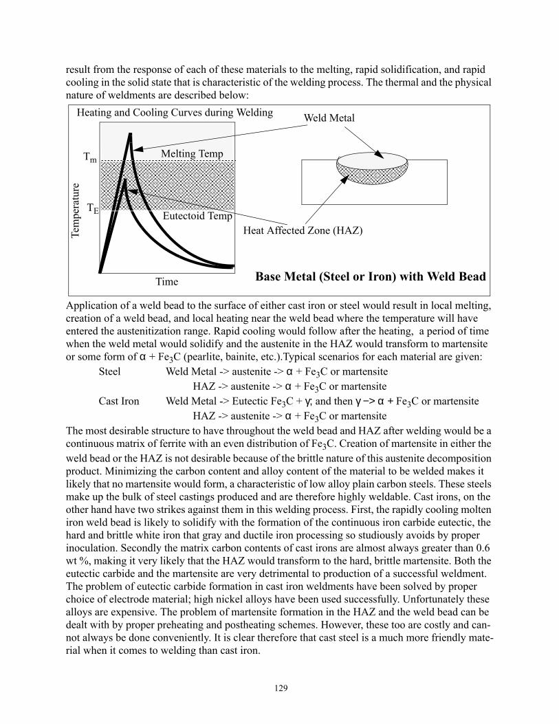
129
result from the response of each of these materials to the melting, rapid solidification, and rapid cooling in the solid state that is characteristic of the welding process. The thermal and the physical nature of weldments are described below:
Application of a weld bead to the surface of either cast iron or steel would result in local melting, creation of a weld bead, and local heating near the weld bead where the temperature will have entered the austenitization range. Rapid cooling would follow after the heating, a period of time when the weld metal would solidify and the austenite in the HAZ would transform to martensite or some form of α + Fe3C (pearlite, bainite, etc.).Typical scenarios for each material are given:
Steel Weld Metal -> austenite -> α + Fe3C or martensite HAZ -> austenite -> α + Fe3C or martensite
Cast Iron Weld Metal -> Eutectic Fe3C + γ; and then γ −> α + Fe3C or martensite HAZ -> austenite -> α + Fe3C or martensite
The most desirable structure to have throughout the weld bead and HAZ after welding would be a continuous matrix of ferrite with an even distribution of Fe3C. Creation of martensite in either the weld bead or the HAZ is not desirable because of the brittle nature of this austenite decomposition product. Minimizing the carbon content and alloy content of the material to be welded makes it likely that no martensite would form, a characteristic of low alloy plain carbon steels. These steels make up the bulk of steel castings produced and are therefore highly weldable. Cast irons, on the other hand have two strikes against them in this welding process. First, the rapidly cooling molten iron weld bead is likely to solidify with the formation of the continuous iron carbide eutectic, the hard and brittle white iron that gray and ductile iron processing so studiously avoids by proper inoculation. Secondly the matrix carbon contents of cast irons are almost always greater than 0.6 wt %, making it very likely that the HAZ would transform to the hard, brittle martensite. Both the eutectic carbide and the martensite are very detrimental to production of a successful weldment. The problem of eutectic carbide formation in cast iron weldments have been solved by proper choice of electrode material; high nickel alloys have been used successfully. Unfortunately these alloys are expensive. The problem of martensite formation in the HAZ and the weld bead can be dealt with by proper preheating and postheating schemes. However, these too are costly and can-not always be done conveniently. It is clear therefore that cast steel is a much more friendly mate-rial when it comes to welding than cast iron.
������������������������������������������������������������������������������������������������������������������������������������������������������������������������������������������������������������������������������������������������������������������������������������������������������������������������������������������������������������������������������������������������������������������������������������������������������������������������������
Tem
pera
ture
Time
Tm
������������������������������������������������������������������������������������������������������������������������������������������������������������������������������������������������������������������
� �������������������������������������������������������������������������������
� ������������������������������������������������������������������������������TE
Melting Temp
Eutectoid Temp
Weld Metal
Heat Affected Zone (HAZ)
Base Metal (Steel or Iron) with Weld Bead
Heating and Cooling Curves during Welding

130
Surface Hardening of Steel and Iron Castings by Selective Heat TreatmentThere are many applications of steel and iron castings in which the desired properties are
achieved by selective heat treatment of surfaces, a process in which a thin surface layer is austen-itized very quickly followed by a rapid quenching action in which the austenite is allowed to transform to martensite or some other combination of phases. The objective is usually to produce a very hard, wear resistant surface while retaining a tough ductile core. Success in these processes requires that the starting microstructure be of a type (pearlite, bainite, tempered martensite) which will respond to the austenitizing treatment in the short time available. All of these structures have very small iron carbide particles in a matrix of ferrite, a combination which is amenable to auste-nitization in short times because of the small diffusion distances requiredto allow the austenite to form. Processes which commonly are used to create these kinds of structures include induction hardening, flame hardening and laser hardening. Details of these treatments are given in many texts on heat treatment. A surface treatment process is illustrated here for surface hardening of a camshaft similar to those used on automobiles. In the diagram below, the conventionally surface hardened cam lobe is illustrated on the right, and the surface austempered lobe is shown on the left. The conventional treatment results in the production of martensite as-quenched which is sub-
sequently tempered to the necessary hardness, a treatment which can be performed on both cast irons and steels. Surface austempering to produce an ausferrite structure can only be done with cast irons. It has been observed that these surface ausferrite structures wear as well or better than the tempered martensite, the austenite matrix transforming to a hard, durable martensite in ser-vice.
Camshaft
1. Cam Lobe SurfaceHeated to 1600oFto a depth of 0.12 in.
2. Austenite Quenched in water to form 100% Martensite in0.12 in. layer.
3. Tempered at 400oFto retain 55RC for Wear Resistance
Lobes
ConventionalAustempered1. Cam Lobe SurfaceHeated to 1600oFto a depth of 0.12 in.2. Austenite Quenchedin Salt Bath at 650oF
to form 100% Ausferritein 0.12 in. layer.
and held for time needed
AusferriteLayer
Tem. Mart.Layer
(Cast Iron) (Cast Iron or Steel)
Cam

131
XVII. Cast Copper AlloysCast copper alloys have a broad range of application, used in every market category from
plumbing to precision electronic components to marine and nuclear equipment. Cast copper alloys are selected most often for their excellent corrosion resistance, favorable mechanical prop-erties, good friction and wear properties, bifouling resistance (inhibiting marine organisms from attaching themselves to submerged surfaces), high electrical and thermal conductivity, good castability and excellent machinability and fabricability.
Like other cast materials, solidification of copper based alloys usually takes place by nucleation and growth of dendrites of a copper-rich face centered cubic solid solution in which all of the problems associated with dendritic growth can and will occur. These problems include microsegregation of alloying elements within the dendrites producing cored structures, entrap-ment of solidification shrinkage and gas porosity in between dendrite arms, and the presence of complex interdendritic phases. In addition, like the transformations that occur in aluminum and ferrous alloys, solid state phase transformations such as eutectoid transformations, martensitic transformations and precipitation hardening are all possible in these materials. It is beyond the scope of these notes to discuss all of the possibilities that exist in the production of castings of copper base alloys. It is useful, however, to provide a more detailed look at casting of a Cu - Sn- Ni alloy, a material which has potential for excellent wear resistance and strength. The appropriate phase diagram is a ternary in which the Ni is completely soluble in the Cu in the solid state and the Sn is soluble up to about 13 wt. % in the solid state.Schematic phase diagrams of the Cu - Ni and Cu-Sn systems are given below:
Consider an alloy with 10 wt. pct. Sn and 5 wt. Pct Ni. Examination of the binary phase diagrams above shows the complete solubility of Ni in Cu in the solid solution α, and the solubil-ity of about 13 % Sn also in α. The Cu - Ni phase diagram contains a miscibility gap at low tem-peratures, where the single phase α solid solution of composition C0 will separate into two α phases α’ + α” of composition C’ and C” respectively at temperature T1, phases with the identical crystal structure of the parent α but with different compositions as dictated by the tie lines on the phase diagram. It can also be seen that the Cu - Sn phase diagram is quite complex, with a number of intermetallic phases present in equilibrium with α between melting and room temperature. It can also be seen that the equilibrium distribution coefficients of Ni in Cu and Sn in Cu are of
Wt. Percent Nickel
Tem
pera
ture
Cu Ni
Liquid
α
��
�
��������������
� �������������������
��
��
��������������������
C0Wt. Percent Tin
Cu 10
13.5
Tem
pera
ture
1083 oC
1083 oC α
Lα + L
βα + β
α + γα + δ
α + ε
�
�
������������
1455 oC
kNi = 1.8 kSn = 0.15
� ��������������������������������������
� �������������������������������������
� �������������������
322oC
α' + α”� ����������������������������������������������������
�
�
���� T1
�
�
���
�
�
���
C’ C”5

132
opposite sign. The Ni atoms segregate negatively, that is there will be more Ni in the first to freeze (FTF) part of the dendrite than at the edge of the dendrite, the last to freeze (LTF) volume; on the other hand Sn atoms segregate positively, with less Sn in the FTF than in the LTF. Thus a compo-sition profile across the α dendrite in such an alloy would have the general appearance as is shown in the sketch below:
The above schematic is not quite accurate because in a 10 percent Sn alloy there will be a signif-icant amount of the interdendritic δ phase which results from the non-equilibrium coring during solidification. This interdendritic phase is a rather hard intermetallic compound which will con-tribute to the wear resistance of the casting; binary alloys of 10% Sn are used in gear applications where good sliding wear resistance is necessary, wear resistance provided in large measure by the interdendritic δ. The rather high level of Ni within the dendrite promotes a certain amount of solid solution strengthening of the dendrite, but has the added potential for contributing much more strengthening to this material by precipitation hardening. This hardening is accomplished through formation of the coherent a’ + a” phases on aging the casting at low temperatures. These phases are illustrated on the phase diagram on page 128, but form in a manner quite different than a nor-mal nucleation and growth process. Instead of the precipitates nucleating and growing individu-ally the α’ + α” phases grow as composition waves within the structure as illustrated below:
In this transformation (sometimes called spinodal decomposition) a random composition varia-tion of composition C0 at time t0 will spontaneously increase in amplitude (composition) with
Wt. Fraction Solidified0
FTF1
LTF
� ������������������������������������������������������������������������������������������������������������������������������������������������������������
� ������������������������������������������������������������������������������������������������������������������������������������������������������������
� ������������������������������������������������������������������������������������������������������������������������������������������������������������
� �����������������������������������������������������������������������������������������������������������������������������������������������������������
� �����������������������������������������������������������������������������������������������������������������������������������������������������������
� �����������������������������������������������������������������������������������������������������������������������������������������������������������
Nickel
12
10
8
6
4
2
0
���������������������������������������������������
����������������������������������������������������������������
�����������������������������������������������������������������������������������������������������������������������������������������������������������������������������������������������������������������������������������������������������������������������������������������������������������������������������
���������������������������������������������������������������������������������������������������������������������������������������������������������������������������������������������������������������������
������������������������������������������������
����������
Tin
Wei
ght P
ct A
lloy
Distance x
Wt.
Pct N
i
���������������������������������������������������������������������������������������������������������������������������������������������������������������������������������������������������������������������������������������������������������
�����������������������������������������������������������������������������������������������������������������������C0
�������������������������������������������������
���������������������������������������������������������������������������������������
����������������������������������������������������������������������������������������������������������������������������������������
������������������������������������������������������������������������������������������������������������������������������������������������������������
������������������������������������������������������������������������������������������������������������������������������������������������������������
������������������������������������������������������������
��������
������������������������������������
������������������������������������������������������������������������������������������������������
������������������������������������������������������������������������������������������������������������������������������������������������������
�����������������������������������������������������������������������������������������������������������������
������������������������������������������
����������������������������������������������������������������������������������������������������������������������������������
��������������������������������������������������������������������������������������������������������������������������������������������������������������������������
������������������������������������������������������������������������������������
������������������������
���
�� ���������������������������������������������������������������������������������������������������������������������������������������������������������������������������������������
����
��
��������������������������������������������������������������������������������������������������������������������������������������������������������������������������������������������������������������������������������������������������������������������������������������������������������������������������������������������������������������������������
C”
C’
t3t2t1
t0
α”
α’

133
aging time until the composition limits C’ and C” are reached by the composition wave. This composition variation creates barriers to defect motion and therefore strengthens the matrix. An age hardening response for an alloy containing 10.5 Sn and 4.4 Ni in the as - cast condition is shown in the figure below:
It should be noticed that the hardness increase on aging was much greater at 350oC than at 425oC, a consequence of the larger composition difference (C” - C’) at 350 than at 425oC. See the phase diagram on pg. 128 to appreciate how this difference increases with decreasing temperature. This increase in hardness resulted in significant increases in tensile strength as well. These results are
0 4 8 12 16 20 24 28 32Aging Time (Hours)
220
200
180
160
140
120
350 oC425 oC
Aging Response of an As-Cast Cu - 10.5 Sn - 4.4 Ni Alloy (Split Cast Iron Mold, 1 in.Plate)

134
illustrated in the Figure below for specimens aged at 350oC.
This figure also illustrates the large gain in elongation following solution treatment at 780oC, a process whereby most of the Ni and Sn available for precipitation were put back into solution. It is interesting to note that the yield, a parameter which is very dependent on the microstructure of the matrix, is much more sensitive to aging than the UTS.XVIII. Homogenization of Castings
Most alloy castings have significant segregation present in the as-cast structure, a result which is usually detrimental to the mechanical properties of the casting. This segregation can take the form of gradients in composition across dendrites or as interdendritic phases which would not be present at equilibrium. Removal or elimination of this segregation requires heating to tempera-tures near the melting point and holding for a period of time sufficient to allow diffusion of the atomic species involved. Singh and Flemings have analyzed the kinetics of homogenization in cast Al - Cu alloys, alloys in which both Cu gradients and the non-equilibrium interdendritic θ phase is present. A part of the Al - Cu phase diagram, microstructure and expected Cu gradient for
70
60
50
40
30
200 10 20 30 40 50 60
Percent Elongation
UTSYield
AsCast Solution
Treated780C,8 Hr
& Aged350C
4.5 Hr
As-Cast &Aged
Variation of Tensile Properties of Cast 10.5 Sn - 4.4 Ni alloy with Heat Treatment
As-Cast
350C, 8 Hr
As-Cast Ppts
into Solution
Creating
New Ppts

135
an Al - 4.5 % Cu alloy are given in the sketch below:
It can be seen in the above sketch of the Cu concentration vs. distance that a significant fraction of Cu is present as the θ phase; an eyeball estimate of the average concentration of Cu in the dendrite is about 1.5 %. Thus the θ phase must contain about 3 % (4.5 - 1.5) of the Cu; this translates to about 6 wt % of the interdendritic q phase in the as-cast condition in an alloy in which the equilib-rium structure would contain none of the θ phase after solidification is complete (see diagram above). The primary reason why Cu is added to Al is to take advantage of the potential for age hardening the matrix a phase (this is the basis for the development of the 2000 series wrought alu-minum alloys). Unfortunately for the cast alloy, as is seen in the above sketch, most of the Cu is not available on direct aging for the generation of precipitates. Thus it becomes necessary to homogenize (or solutionize) the cast material, to put the Cu atoms into solution in the aluminum rich matrix (dissolve the θ phase particles) so that then the alloy can be heat treated to take advan-tage of the Cu that is present.
Singh and Flemings showed that the rate at which the θ phase would dissolve into the a phase is a function of the diffusion coefficient of Cu in the Matrix, DCu, and the secondary den-drite arm spacing, d. Their expression for the variation of the volume fraction of the θ phase, Xθ, with time at temperature is given by:
Xθ = Xθo exp - [π2Dt / d2]where:
Xθo = Volume fraction of θ in as-cast condition,t = time.
Heat treatment to homogenize requires that the casting be heated up into the single phase α field, to a temperature range of about 520 to 570 oC. It can be seen in the above equation that the value of Xθ will decrease with time in an exponential fashion until (at an infinite time) all of the inter-dendritic phase will be dissolved into the dendritic matrix. Clearly this is not practically accept-able; rather it is necessary only to put most of the Cu into solution in the dendrites. Assuming that 95 percent of the θ phase is an acceptable amount to be dissolved into the matrix α gives an expression for the time for homogenization, tH of:
Dendrite Center Interdendritic Cu -rich θ Phase
Microprobe Line Scan Position
0 Distance
53.5 Wt % Cu
53.5
5.65
Center of Interdendriticθ Phase
C0 = 4.5
kC0 = 0.77 θ
α L
α + θ
Al 33Wt.% Cu
Maximum Solubility of Cu
53.54.5
across Dendrite
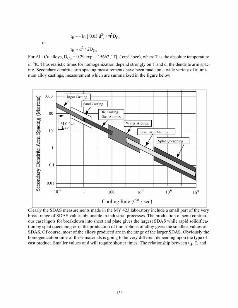
136
tH = - ln [ 0.05 d2] / π2DCuor
tH ~ d2 / 2DCu
For Al - Cu alloys, DCu = 0.29 exp [- 15662 / T], ( cm2 / sec), where T is the absolute temperature in oK. Thus realistic times for homogenization depend strongly on T and d, the dendrite arm spac-ing. Secondary dendrite arm spacing measurements have been made on a wide variety of alumi-num alloy castings, measurement which are summarized in the figure below:
Clearly the SDAS measurements made in the MY 423 laboratory include a small part of the very broad range of SDAS values obtainable in industrial processes. The production of semi continu-ous cast ingots for breakdown into sheet and plate gives the largest SDAS while rapid solidifica-tion by splat quenching or in the production of thin ribbons of alloy gives the smallest values of SDAS. Of course, most of the alloys produced are in the range of the larger SDAS. Obviously the homogenization time of these materials is going to be very different depending upon the type of cast product. Smaller values of d will require shorter times. The relationship between tH, T, and
Cooling Rate (Co / sec)
1000
100
10
1
0.1
0.01
10-2 1 100 104 106 108
Ingot Casting
Sand Casting
Die CastingGas Atomiz.
Water Atomiz.
Laser Skin Melting
Splat Quenching
MY 423Lab

137
SDAS, d, is summarized in the Figure below:
It can be seen in this figure that homogenization of large ingots take on the order of days to suc-cessfully dissolve the interdendritic phases, where atomized powders require times that are insig-nificant. Certainly the homogenization cost can be reduced if effort is taken to reduce SDAS by increasing the cooling rate. Thus there is a large driving force to produce continuous cast strip on the order of a few centimeters thick. This would reduce energy costs to homogenize as well as to break down by rolling. This is the direction that nonferrous metals is taking, following the contin-uous casting example set in steel, where it is currently possible to continuously cast strip on the order of inches in thickness.
It should be mentioned that the above relationship for tH is generally usable with other castings as well, plugging in the appropriate diffusion coefficients. This “rule of thumb” relation-
Secondary Dendrite Arm Spacing, d (Microns)
1 10 100 10000.10.01
107
106
105
104
103
102
10
1
10-1
10-2
10-3
450oC 500oC
550oC
INGOTS
DIE & SAND CASTING
ATOMIZA TION
One Week
One Day
One Hour
One Minute

138
ship applies even though there may be no significant interdendritic phase, for situations in which there are only composition variations from inside the dendites to outside of the dendrites. A selected group of diffusion coefficient data is given in Table 12:
Problem: A ductile cast iron with a nominal composition 3.7 C, 1.99 Si, 0.29 Mn, 0.18 Mo, 1.33 Ni, 0.77 Cu, 0.052 Mg was produced at MTU and cast into sand molds (4 inch Y-Block). The ele-ments Si, Ni, and Cu segregate negatively (high concentration in the center of the dendrites and near the nodules[FTF], while Mn and Mo segregate positively (high concentrations in the inter-dendritic regions [LTF]). The extremes in concentration observed in this alloy is given in the table below:
Table 12: Selected Diffusion Coefficients in Al, Cu and Fe
D = D0 exp [-Q/RT], (cm2 / sec)
Matrix Solute D0 Q/R(oK)
Al Cu 0.29 15662
Al Mg 4.4 16859
Al Li 4.5 16759
Cu Ni 1.4 27428
Cu Sn 0.027 18762
Cu Zn 0.083 (for 10% Zn) 19879
Fe, In Austenite Mn 0.055 29995
Fe, In Austenite Mo 0.068 29693
Fe, In Austenite Ni 0.344 32964
Fe, In Austenite N 0.91 20262
Fe, In Austenite C 16.2 16575
Fe, In Austenite Si (0 -2%) DSi = 4 x 10⁻¹⁰(1206oC), 1.7 x 10⁻⁹ (1293oC)
Fe, In Austenite Cu 3.6 32964
Data from Smithell’s Metal Reference Book; Shewmon’s Text, Diffusion in Solids
Table 13:
Location Si Ni Cu Mn Mo
FTF 2.9 1.65 1.55 0.2 0.05
LTF 1.0 0.65 0.3 1.1 1.7

139
The SDAS observed in this heavy section casting was in the range of 200 microns (0.02 cm). Show that homogenization of this alloy is not practical (Tm = 1150oC).XIX. Environmental Concerns in Metal CastingProduct Life Cycle and the Environmental Concern EnvelopeEverything material has a life cycle, which means there is a birth, a useful life, and a death. Obvi-ously the most desirable situation is one in which the useful life is infinite. Of course this is purely wishful thinking because of wear, corrosion, and obsolescence. A Product Life Cycle begins when raw materials are brought together for the purpose of producing or manufacturing a specific product for consumption by the public. In the past the product life cycle ended when the specific product reached the end of its useful life. A general schematic of this process for a system in which there was no closure (including mining) is given below.
In this modern age of environmental concern, the product life cycle has been modified to include closure of the life cycle and to reflect the concern for the environmental “cost” of producing and using the product. This “cost” includes an awareness , both qualitative and quantitative, of the energy and material inputs and outputs during the process of producing the product. The Product Life Cycle indicated above has been updated to reflect the Environmental Cost in the figure on page 137. In this Figure the several options of Life Cycle Closure (Recycling, Remanufacturing or Reusing) are included together with the introduction of the Environmental Concern Envelope. This envelope emphasizes the material and energy inputs and the solid, liquid, and gaseous out-
Product Life Cycle, No Closure
ResourceExtraction
Product Manufacturing
Packaging& Transport
ProductUse
Product Disposal
Landfill

140
puts resulting from processes throughout the cycle.
The primary difference in the product life cycles as depicted by these figures is the closure through recycling, reuse, or remanufacturing shown above. The driving force for closure is clearly a combination of the desire by manufacturing centers to reduce their costs to produce the product, together with the need to comply with existing and future environmental regulation. It will be the responsibility of the designer of the future to consider the environmental envelope at the begin-ning of the product life cycle, to minimize the impact of the product manufacturing and use on the environment by minimizing energy and material requirements and minimizing deleterious mate-rial outputs. Obviously the goal of the designer will be to produce a product with zero negative discharges, to select and help design products and processes which generate useful byproducts instead of outputs which will materially harm the environment.Product Life, Dissipation of MassThe second law of thermodynamics, with its requirement that entropy increases (that randomness prevails) can be demonstrated by a critical look at the fate of products. In a discussion of product
Product Life Cycle,ENVIRONMENTAL CONCERN ENVELOPE
ResourceExtraction
Product Manufacturing
Packaging& Transport
ProductUse
Product Disposal
LandfillReuse or
Remanufacturing
Recycling
SOLID WASTE BURDEN
AIR AND WATER POLLUTION

141
life cycles, it is useful to look at whether or not product matter is dissipated during the lifetime of the product and/or after it has ceased to be useful. In this discussion, dissipation implies loss of mass external to the product. A schematic product life—dissipation diagram,shown below, illus-trates product use on a scale from “dissipative” to “non-dissipative.” This figure shows that highly dissipative products are those which are usually produced for their controlled chemical reactions (gasoline, blast furnace coke, explosives, fertilizer, pesticides), while non-dissipative products are most often produced for their electronic or electrical properties (TVs, computers, batteries). In the former, the reaction products are invariably dissipated to the environment and cannot be conveniently recovered. In the latter, the product does not dissipate matter to its sur-roundings but ceases to be useful by obsolescence, by nonreversible chemical reactions, or by internal mass flow. In many of these instances, it is interesting to note that product function ceases by atomic dissipation (diffusion) within the product and not by dissipation to the environ-ment. The “in between” products shown below invariably have a component of mechanical or chemical use in which dissipation of matter can occur to different degrees depending upon the product. This is illustrated by automotive parts which move against other parts and lose mass by wear, and by auto body parts which corrode. If there is enough wear or corrosion, the part will eventually cease to function and will require replacement or repair.
Material Flow in a Metal Casting FacilityThe majority of metal castings produced in the world are made by pouring molten metal into a sand mold made of sand grains (Usually Silica, SiO2) which are bound together by a variety of binder materials including clay-water and a large variety of organic and inorganic chemicals. These kinds of manufacturing facilities, like most manufacturing facilities, experience large quantities of materials moving in response to the needs of the process. Metal movement occurs in the solid and liquid state, sand in huge quantities (sand / metal ratios of 3-10) are needed to make the molds, air flow is required to move and remove combustion products, water is needed
Products
Useful Product Life
Dissipative UseNon-Dissipative Use
Decreasing Tendency to DissipateIncreasing Tendency to Dissipate
Chemical Uses Mechanical UsesElectronic or
Electrical Uses
GasolineCokeExplosivesFertilizersPesticides
Automobile Brake PadsAutomobile Disc Brake Rotors
Internal Combustion EnginesAutomobile Bodies
Foundry Sand
TelevisionsComputersBatteriesCopper CableBeverage Cans
NOT RECYCLABLE GENERALLY RECYCLABLE
Product Life - Dissipation Diagram

142
for cooling and scrubbing air, and chemicals are sometimes necessary to bind sand grains and cre-ate metal penetration resistant layers. This dynamic flow situation is illustrated schematically below, a flow diagram which is representative of a foundry of 1950. In this schematic the solids
are depicted as entering the casting process from right and left, the water enters from the bottom, and the air enters from the top. All material input is focussed upon the casting process in the cen-ter of the figure. Note that in 1950 the only recycled material was the metal, the remaining solid, liquid and gas being dispensable. As a result of environmental, financial, and social pressures, the foundry industry, like most other American industry has responded by paying much more atten-tion to the flow of materials, other than the metals which make up their product, into and out of their manufacturing centers. Those materials, gases, solids, and liquids, which are absolutely nec-essary in the process of producing the product but don’t appear in the product are also very impor-tant This concern is illustrated schematically in the figure on page 140, a schematic flow diagram for a typical foundry in the year 2000, in which solid, liquid and gaseous waste problems are
Repro-
Sand
MetalReturns cessed
ConsumerCASTING
SCRAPMETAL
[IN]
To Scrapyard
Disposal in Land•ll
AIR [IN]
DUSTCHEMICALSAIR
[OUT]
WATER [IN]SLUDGECHEMICALSWATER
[OUT]
OTHER CHEMICALSBINDERSSAND[IN]
SPENT SAND
[TO LANDFILL]
FOUNDRYBOUNDARY
Schematic Material Flow in Foundry, A D 1950

143
being addressed by attempts to “close the loops” with appropriate technology.
It can be seen that the solid, liquid, and gas loops have been closed by the incorporation of devices for scrubbing and cleaning the air and water, and by sand reclamation devices which will scrub the sand grains for reuse. These efforts to control material flow into and out of metal casting plants have been made in response to the need to improve the environment of people. Environ-mental specialists within the industry respond to health concerns related to the industrial output of solids, liquids, and gases affecting workers (close proximity to the industrial output), affecting near neighbors (within a few blocks of the industrial setting), and all residents on earth (green house gas emission, acid rain, etc.).
Spent Molding MediaThe greatest fraction of castings produced are made in molds in which an aggregate of some refractory material is used as molding media, most often silica sand. As described earlier in these notes, the process of making molds requires a pattern around which sand with an appropriate bonding medium is packed. The pattern is removed, leaving a cavity in the sand into which mol-ten metal is poured. As indicated previously, bonding media vary from clay + H2O to complex organic resins which, as a result of the heat from the liquid metal, burn and produce a residual
Repro-
Sand
MetalReturns cessed
ConsumerCASTING
SCRAP METAL[IN]
AIR [IN]
AIR[OUT]
WATER
OTHER CHEMICALSBINDERS
SAND[IN]
SPENT SAND
WaterTreatment [IN]
Sand ReclamationTo Disassembly
for RemanufactureRecycle or Reuse
Air TreatmentBaghouse
WATER[RECIRCULATED]
Sludge
Dust
Waste forDisposal
Byproduct from Dust
FOUNDRYBOUNDARY
Material Flow in a Foundry in AD 2000

144
coating on the sand grain surfaces. This new carbon-containing surface results in difficulty in rebonding the shakeout sand. As a result, a significant amount of this “spent sand” is disposed of in landfills (1 million tons per year in Michigan and 15 million tons in the U.S., 1990 estimate). The figure below is a schematic flow diagram for sand in a typical green sand (clay-water bond) foundry. This figure shows that after the casting operation the shakeout sand is divided into two components. The major component is reused for making new molds (reconditioned sand), while the minor component is treated as waste, screened fines and lumps created by the contact with high temperatures.
There are opportunities available for sand (lumps and fines shown above) which is no longer sat-isfactory for direct use in molding, including:A. Subjecting the sand grains to a cleaning process whereby the interfering layer is removed
Mining of SandDunes and Old Lake Beds
Washing, Screening,and Sizing
Production ofMolds and Cores
Bonding Media
Pouring of Molten Metal into
Sand Molds
CASTINGS
ReconditionedSand
Separation of Castingsfrom Sand
[SHAKEOUT]
Shakeout Sand
2. Heat Affected Sand (Lumps, Fines)1. Sand Unaffected by Heat
Screened Lumps &Fines Removal
Add Waterand clay
Molding Sand Core SandAdd Waterand clay
RECLAMATIONMechanical and ThermalScrubbing of Sand Grains
To Landfillor Alternate UseFines

145
so that the grains can be used again as molding medium. These cleaning processes are generically called reclamation and are shown closing the product cycle in the above sketch. This process is an expensive addition to the foundry handling system and has been discussed in some detail on pages 64 - 67 of these notes.B. Using the sand grains (lumps and fines) for an alternate use, some of which are:
1. Aggregate in asphalt2. Aggregate in concrete3. Charge stock in a cement kiln4. Charge stock in glass making5. Daily cover in a landfill
Option A is not currently in wide use in the State of Michigan because for many foundries it is not yet cost effective; i.e., the cost of landfilling is still not high enough to offset the increased capital cost requirement to clean these grains. However, the rate of increase in the cost of disposal is large, and it is simply a matter of time before Option A will become attractive and become a part or the sand system in each foundry. Option B is in its beginning stage, with B1, B3 and B5 cur-rently in process in several locations in this country. Which option each foundry uses will depend upon its own unique circumstances.
Environmental Concern of Metal Casting Facilities.Metal casting facilities have long been known as “recyclers” because of their basic func-
tion of taking scrap metal and turning it into useful products. Unfortunately, because of the other material needs of these processes which are described above, metal casting facilities had also earned the reputation of being very dirty places to work at or live near. This reputation has changed, however, with governmental pressure responding to peoples’ physical and health needs as well as the drive for environmental responsibility on the part of industry. As a result of these pressures, significant federal legislation has been passed which has been directed at forcing clo-sure of the above loops illustrated on page 140, legislation dealing with clean water, clean air, and the generation and disposal of solid waste, both hazardous and non-hazardous. A partial summary of the most significant of these legislations is given below:
1963 - Clean Air Act (CAA)1965 - Solid Waste Disposal Act - First Law dealing with safe disposal of household,
municipal, commercial and industrial waste.1970 - Resource Recovery Act1970 - Clean Air Act (CAA), Amendments to CAA, Most of Basic Structure of CAA
were established in these amendments - Emission Standards for industrialplants and automobiles.
1970 - Clean Water Act (CWA)1976 - Resource Conservation and Recovery Act (RCRA) - regulates generation, storage,
transportation, treatment and disposal of hazardous waste1977 - Clean Air Act, Amendments to CAA1977 - Clean Water Act, Requires at least secondary treatment of all publicly owned treat-
ment works, stipulating that such facilities provide at least 85% BOD (bio-chemical oxygen demand) removal.
1980 - Comprehensive Environmental Response, Compensation and Liability Act (CER-CLA) , Requires Cleanup of sites which pose a threat to human health or
146
the environment (Superfund), Amendment to RCRA1984 - Hazardous and Solid Waste Amendments, Amendment to RCRA1986 - Superfund Amendments and Reauthorization Acts (SARA) 1990 - Clean Air Act Amendments (Goal to reduce air pollution by 90% by year 2000)
EPA (Environmental Protection Agency) Identified Iron and Steel Found-ries as potential major source categories of acrolein, benzene, Cr, Co, Pb, Mn, Ni, Se, formaldehyde, phenol, toluene, xylene, polycyclic organic matter. This from a list of 189 hazardous air pollutants (HAP) added to existing list from 1970
All of these legislations have had and do affect the manner in which metal casting facili-ties deal with their own solid, liquid,and gaseous waste, and therefore their own processes. The net result of these far-reaching environmental laws has been that metal casting facilities are very sensitive to any change, or potential change in their process which could improve their current environmental position. Whereas most industrial producers of castings didn’t even know what an environmental engineer was in the mid 1960s, the necessity to comply with the law has seen a large increase in the number of environmental engineers in positions of responsibility. Indeed it is not an exaggeration to say that all engineers currently employed in most industrial situations will find their careers being driven in part by environmental concerns.
The ideal industrial organization, from an environmental point of view, would know exactly what materials are entering their facility and have complete control of what happens to those materials in that facility, so that nothing leaves the process in any way, shape, or form which could now or in the future be a danger to human health. Clearly this is an impossible task for metal casting plants which use and handle large quantities of materials. Rather than expecting to achieve the ideal situation, foundries of the present and future will need to optimize their pro-cesses to minimize the potential danger from emissions which exit their work space. On examina-tion of the loops in the schematic on page 140, one’s eyes are drawn to the center of the foundry enclosure, the focus point of all of the inputs and outputs where casting of the metal takes place. It is clear that minimizing the potentially dangerous emissions from each process will require know-ing much more about the materials which are going into the process and understanding what hap-pens to materials during the process. The inputs and outputs and the processes involved in a

147
hypothetical green sand foundry is illustrated in the schematics that follow:
It is the foundry’s responsibility, according to the federal laws summarized on pages 142 & 143, to be responsible for the materials generated in the foundry processes. The schematic above shows significant outputs other than the primary output, castings, all of which are potential sources of pollution. All five of the outputs listed (other than castings) constitute waste products which could contain toxic components, components which according to the law require mitiga-tion in one way or another. Two examples follow in which the law is applied to current practice. CAA of 1990
Consider the complexity of this situation where volatiles are concerned. Potentially harm-ful gases can be generated in many of the common processes involved in producing castings, as illustrated by the arrows in the above schematic. These gases include CO and CO2 from combus-tion during melting and casting, many potentially toxic combustion gases from the organic binder materials, solvents associated with painting processes, etc. Most of the CO and CO2, as well as a good fraction of the combustion products from core binders is released to the atmosphere in the foundry, or is captured by the air handling system and released external to the foundry. Some of these gases will find their way into a scrubber system and can be captured in a sludge as the gas-eous species or as another reacted compound. Most, however, will escape and be emitted into the surrounding atmosphere. According to G. Mosher, the Director of Environmental Affairs for the American Foundrymen’s Society (Modern Casting, October, 1994, pages 28 - 31) it is the intent of the current law that state air pollution agencies will, in the future, require each foundry to supply information about what hazardous air pollutants and how much of each (of the 189 hazard-ous air pollutants defined by Congress) they emit per year before operating permits can be obtained. There are two ways this information can be obtained. First, and most expensive, stack tests can be obtained and air samples analyzed for their content. Accurate analysis, however, requires very careful sampling over a reasonable time span. The second way to answer this ques-tion (satisfactorily for the EPA) is to use the EPA’s Emission Factors, factors based upon 1970s AFS research done on emissions due to binder combustion. This requires knowing how much of a particular binder is used in a given facility per year and then simply summing the various combus-tion products,as determined by the AFS research, from that binder. As an example Table 14 sum-
MeltingINPUTS OUTPUTS
Scrap MetalSandChemicalsAirOther GasesWater
Volatiles (Gases)DustsSludgesSlagsSpent Sands
CastingCore MakingMold MakingCasting ShakeoutSand ProcessingReclamationCasting CleaningCasting Painting
Foundry Boundary
Inputs and Outputs Illustrating the Sources of Volatiles in a Typical Foundry
PROCESS ENVELOPE
Castings

148
marizes the emissions from 1 pound of a phenolic No-Bake binder (This assumes that the binder is completely combusted in a manner typical for a ferrous foundry).
Emission Factors for 12 of the most common binders or sand additives are available for calcula-tional purposes. Granting of an operating permit will depend upon the individual state’s law and on the total amount of HAP emitted per annum.
This method is a common sense approach (What Goes In Must Come Out) and a conser-vative estimate of emissions, because all of the binder is assumed to be combusted during the casting operation. However, it is common knowledge that a significant part of the binder will be lost to solid waste streams, most notably the core butts and broken cores which never see the heat of molten metal. Thus the foundry can be fairly confident of their air emission responsibility pro-vided that they keep good records of the input binder purchases.RCRA of 1976
The Resource Conservation and Recovery Act of 1976 regulates the generation, storage, handling and disposal of toxic waste material. A toxic substance is harmful or fatal if ingested or absorbed. Toxicity is determined using a standardized laboratory test called the extraction proce-dure, a process which in essence is supposed to simulate the leaching action which could occur if the substance were allowed to be exposed to rainfall in an open landfill. A substance is designated as being EP Toxic if an extract (the leachate from the test) contains any of the eight toxic ele-ments or six pesticides that follow in concentrations greater than the values given (in milligrams per liter): Arsenic (5); Barium (100); Cadmium (1); Chromium (5); Lead (5); Mercury (0.2); Sele-nium (1); Silver (5); Endrin (0.02); Lindane (0.4); Methoxychlor (10); Toxaphene (0.5); 2,4-D(10); 2,4,5 TP Silvex (1). It should be noted that a hazardous substance is a more all-encompasing term than a toxic substance, though the two are often used interchangeably.
Table 14: Emissions (in lbs) from One Pound of No-Bake Phenolic Resin; after Mosher
EmissionAmnt10-6Lbppm
EmissionAmnt10-6Lbppm
EmissionAmnt10-6Lbppm
NH3 39 Benzene* 11209 Phenol* 975
Total Hydro-carbons
12159 Formalde-hyde*
10 Toluene* 634
NOX 29 HCN* 29 Total Aromatic Amines* 49
SO2 15107 M-Xylene* 97 Total C2 to C5 Aldehydes* 3070
H2S 1462 Napthalene* 49 Total HAPs (With*) 16174
Acroleine* 5 O-Xylene* 49 TOTALS** 44972
** Thus for one pound of binder, 0.0449 pounds of Objectionable gaseous emissions and 0.0162 pounds classified as hazardous emisssions are released to the atmosphere. Presumably the remainder of the one pound of binder will be emitted as the combustion products of water, CO2, and CO (The OSHA emission standard for CO is 50 ppm)

149
According to the EPA there are over 400 listed hazardous wastes and there is more than one ton of hazardous waste per person per year generated in the U.S. (This amounts to ~ 250 million tons of hazardous waste generated in the U.S. Of this amount only a small portion is contrib-uted by metal casting facilities, perhaps - as a guess - only 1 million tons at maximum.) All of the elements in the above list are potentially present in the output from foundries. Certainly lead and cadmium are likely to show up in ferrous materials as carry over from scrap in the charge. This distribution of lead as an impurity is illustrated in the input - output schematic below:
Sources of lead in the charge include 1. Leaded steels (lead is used to improve machinability of steels); 2. Leaded paints on scrap (Lead was a prominent element in paints for many years); 3. Lead included in automobile shredding products (lead-acid batteries). It can be seen from the above schematic that the melting operation results in lead being ever more widely distributed (entropy in action) throughout the foundry work area, perhaps to the immediate neighborhood of the foundry, and to the landfill site through leaching action of rainfall. The foundry is required by law to make sure that emissions of lead from their stacks is within state - accepted tolerances and that the air within their foundry contains no more than a certain allowable maximum amount. Clearly the solution to this problem includes careful monitoring of input charge materials and using an air handling system within the foundry which captures effluent from the melting area by the use of a scrubber ( a device using water to entrap particulate matter) or a baghouse (a big filter which captures particulate matter).Of course, the scrubber sludge and the baghouse dust may now contain lead in quantities large enough to be classified as a toxic waste. This material will then either have to be transported to a toxic waste site (very expensive- ~ 5 to 10 times the cost of a normal landfill fee), or the lead will have to be rendered non-leachable by chemically combining it with another material or by coating the lead particles in a material which will not leach (another costly operation).
While lead is of concern as an impurity in charge materials which then ends up in the bag-house or in scrubber sludge, the fraction of solid waste from metal casting plants which is classi-fied as hazardous is quite small indeed. The largest component of waste materials from foundries is spent sand which, for the most part, is not hazardous and can be disposed of in local landfills at reasonable cost. In fact most of the spent sand from foundries is used for daily cover at the land-
MeltingINPUTS OUTPUTS
Scrap MetalSandChemicalsAirOther GasesWater
Volatiles (Gases)DustsSludgesSlagsSpent Sands
CastingCore MakingMold MakingCasting ShakeoutSand ProcessingReclamationCasting CleaningCasting Painting
Foundry Boundary
Inputs and Outputs Illustrating the Flow of Lead in a Typical Iron or Steel Foundry
PROCESS ENVELOPE
Castings
Pb Pbor PbO
orPbO Hazardous
Waste Land-fill or ChemicalTreatment

150
fill, which usually means that the foundry will pay less per ton to dispose of the spent sand. Even in the instance of lead and cadmium containing dusts and sludges, there are industrial organiza-tions which “mine” these wastes for their heavy metals, and as such will either purchase these “byproducts” from the foundry or will take them at no cost. Of course the monetary exchange is determined by the grade of the “ore” that is the dust or the sludge.Pollution Prevention
The above examples of air emissions and lead emissions are only two environmental con-cerns which foundries face on a daily basis. Obviously there are many other examples as well, examples which will change from one foundry to another, from one metal to another, and even from one state to another (depending on state statutes). The challenge for the foundry industry (and every other industrial sector which uses large quantities of materials) is to look closely at their processes and purchases with the intent of minimizing or eliminating waste. This engineer-ing and management strategy is referred to as pollution prevention, as opposed to the end-of-pipe treatment which has dominated the environmental area for the first 20 years of the environ-mental revolution.
Pollution Prevention in the future of metal casting facilities will require efforts to:1. Take a closer look at the fundamental material handling processes with an eye to implementing design changes which will minimize waste.2. Explore alternate molding media (to sand) with the intent of developing dimensionally more stable aggregates which are more resistant to the rig-ors of metal casting and more reclamation friendly.3. Develop new core and mold binders which will combust more com-pletely and produce a minimum of the hazardous combustion products.4. Develop and use more sophisticated equipments for screening incoming charge material to minimize problems from contaminants such as lead or cadmium.5. Increase the overall industry wide casting yield, by using innovative casting techniques and developing new casting techniques which minimize gating and risering systems.6. Explore new sources of charge material; for example in the cast iron industry take a serious look at direct reduced iron as an alternate to scrap.7. Other?