reference guide: fisher scientific accumet xl …...fisher scientific accumet xl250, xl500, and...
TRANSCRIPT
1
Reference Guide
Fisher Scientific accumet® Excel (XL)
Benchtop Meters
XL150 ● XL200 ● XL250 ● XL500 ● XL600
68X623601 Rev 0 October 2012
2
Table of Contents
1. INTRODUCTION ............................................................................................................................................. 4
2. TOUCH SCREEN & ICONS ............................................................................................................................... 5
3. CONNECTIONS .............................................................................................................................................. 8
4. ELECTRODE BRACKET & ARM ASSEMBLY ....................................................................................................... 9
5. POWER ON/OFF .......................................................................................................................................... 10
6. SYSTEM SETUP ............................................................................................................................................ 11
7. ADMINISTRATION & USER ID ...................................................................................................................... 12
8. PARAMETER SETUP: SAMPLE ID .................................................................................................................. 14
9. PARAMETER SETUP: AUTO READ MODE ..................................................................................................... 15
10. PARAMETER SETUP: STABILITY CRITERIA / STABLE INDICATOR ................................................................... 16
11. PARAMETER SETUP: DEFAULT TEMPERATURE ............................................................................................ 17
12. PARAMETER SETUP: ISOPOTENTIAL POINT ................................................................................................. 18
13. PARAMETER SETUP: ALARM LIMITS ............................................................................................................ 19
14. PARAMETER SETUP: PRINT CRITERIA .......................................................................................................... 20
15. PARAMETER SETUP: DATA STORAGE CRITERIA ........................................................................................... 21
16. PARAMETER SETUP: DISPLAY CRITERIA ....................................................................................................... 22
17. VIEWING & EXPORTING STORED DATA (LOG VIEW) .................................................................................... 23
18. GRAPHING .................................................................................................................................................. 24
19. STANDARDIZATION ..................................................................................................................................... 25
20. TEMPERATURE OPERATION ........................................................................................................................ 26
21. PH OPERATION............................................................................................................................................ 27
22. MILLIVOLT OPERATION ............................................................................................................................... 29
23. ION: SETUP & OPERATION .......................................................................................................................... 30
24. ION: DIRECT READING METHODS ................................................................................................................ 32
25. ION: INCREMENTAL METHODS .................................................................................................................... 34
26. ION: KNOWN ADDITION METHOD .............................................................................................................. 35
27. ION: KNOWN SUBTRACTION METHOD ........................................................................................................ 36
28. ION: ANALATE ADDITION METHOD ............................................................................................................. 37
29. ION: ANALATE SUBTRACTION METHOD ...................................................................................................... 38
30. CONDUCTIVITY / RESISTIVITY OPERATION .................................................................................................. 39
31. TDS OPERATION .......................................................................................................................................... 41
32. SALINITY OPERATION .................................................................................................................................. 42
33. DISSOLVED OXYGEN OPERATION ................................................................................................................ 43
34. BOD OPERATION ......................................................................................................................................... 48
3
35. OUR OPERATION ......................................................................................................................................... 49
36. SOUR OPERATION ....................................................................................................................................... 50
37. FIRMWARE UPGRADE ................................................................................................................................. 51
38. SPECIFICATIONS .......................................................................................................................................... 54
39. REPLACEMENTS & ACCESSORIES ................................................................................................................. 57
40. WARRANTY ................................................................................................................................................. 59
41. RETURN OF ITEMS ....................................................................................................................................... 60
42. NOTICE OF COMPLIANCE ............................................................................................................................. 61
43. DECLARATION OF CONFORMITY ................................................................................................................. 62
4
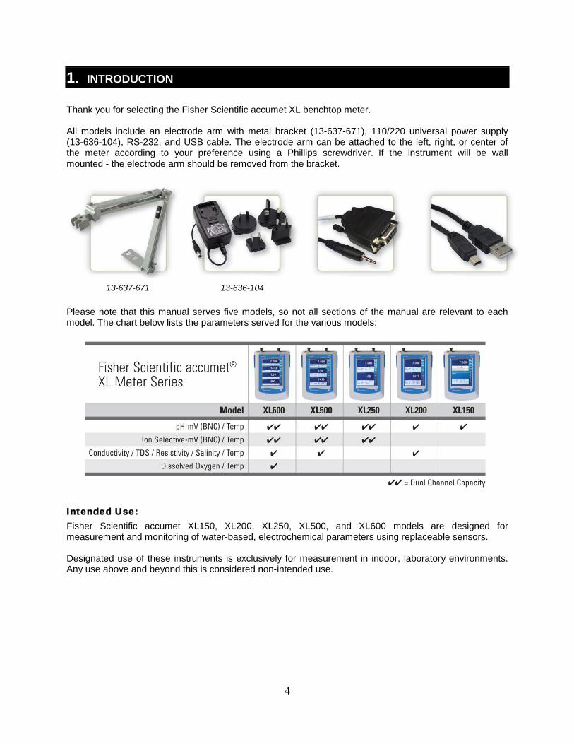
1. INTRODUCTION Thank you for selecting the Fisher Scientific accumet XL benchtop meter. All models include an electrode arm with metal bracket (13-637-671), 110/220 universal power supply (13-636-104), RS-232, and USB cable. The electrode arm can be attached to the left, right, or center of the meter according to your preference using a Phillips screwdriver. If the instrument will be wall mounted - the electrode arm should be removed from the bracket.
13-637-671 13-636-104 Please note that this manual serves five models, so not all sections of the manual are relevant to each model. The chart below lists the parameters served for the various models:
Intended Use: Fisher Scientific accumet XL150, XL200, XL250, XL500, and XL600 models are designed for measurement and monitoring of water-based, electrochemical parameters using replaceable sensors. Designated use of these instruments is exclusively for measurement in indoor, laboratory environments. Any use above and beyond this is considered non-intended use.
5
2. TOUCH SCREEN & ICONS
The Fisher Scientific accumet XL150 / XL200 / XL250 / XL500 / XL600 series benchtop meters operate with a high performance TFT color touch screen. The touch screen can be controlled by a finger or an optional USB mouse. Avoid damage to the display by preventing contact from aggressive chemicals, solvents, hot liquids, and all sharp or pointed objects such as a screwdriver which can damage the screen. A stylus is suitable for normal use if desirable. The buttons on the right side of the screen control all of the functions of the meter. A light touch on the screen is all that you need to access the various functions. If the beep function is enabled, you will get an audible tone with each press on the touch screen. Note: the screen will not change until you lift your finger. This design prevents rapid uncontrolled scrolling through the various function screens. Function buttons and options change from screen to screen. Easy to understand prompts guide you through the operation of the meter in the selected mode. For additional details on the particular screen you are viewing, select “Help” located on the bottom right corner of the display. Your meter was shipped with a clear protective sheet to protect the LCD display and “bubbles” may appear on the screen. The screen will respond better and visibility will improve if it is removed. Alternatively, you may choose to leave this on for added protection.
Maintenance And Precautions: For routine maintenance disconnect the power cord, then dust or wipe the display using a damp cloth. If necessary, warm water or a mild water based detergent can be used. Maintenance can be performed as required by the environment in which the meter is operated. Immediately remove any spilled substance from contact with the meter using the proper cleaning procedure for the type of spill. • Do not use this equipment in potentially explosive atmospheres.
• Refer to the electrode instructions for use, storage, and cleaning.
• Ensure that no liquid enters the instrument.
• Do not use any aggressive cleaning agents (solvents or similar agents).
• The instruments do not have user serviceable parts inside. Attempts to service internal parts may void the warranty.
Here Is A List Of Various Icons And A Summary As To The Function Of Each:
Administration: Use to create and edit user login ID profiles, Passwords, and User Groups.
System Setup: Use to configure and view system settings. These include stirrer speed, printer, touch screen calibration, date & time and brightness settings.
6
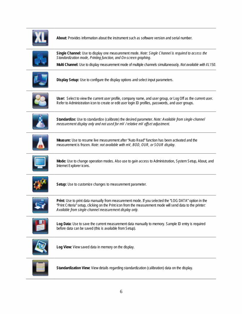
About: Provides information about the instrument such as software version and serial number.
Single Channel: Use to display one measurement mode. Note: Single Channel is required to access the Standardization mode, Printing function, and On-screen graphing.
Multi Channel: Use to display measurement mode of multiple channels simultaneously. Not available with XL150.
Display Setup: Use to configure the display options and select input parameters.
User: Select to view the current user profile, company name, and user group, or Log Off as the current user. Refer to Administration icon to create or edit user login ID profiles, passwords, and user groups.
Standardize: Use to standardize (calibrate) the desired parameter. Note: Available from single-channel measurement display only and not used for mV / relative mV offset adjustment.
Measure: Use to resume live measurement after “Auto Read” function has been activated and the measurement is frozen. Note: not available with mV, BOD, OUR, or SOUR display.
Mode: Use to change operation modes. Also use to gain access to Administration, System Setup, About, and Internet Explorer icons.
Setup: Use to customize changes to measurement parameter.
Print: Use to print data manually from measurement mode. If you selected the “LOG DATA” option in the “Print Criteria” setup, clicking on the Print icon from the measurement mode will send data to the printer: Available from single-channel measurement display only.
Log Data: Use to save the current measurement data manually to memory. Sample ID entry is required before data can be saved (this is available from Setup).
Log View: View saved data in memory on the display.
Standardization View: View details regarding standardization (calibration) data on the display.
7
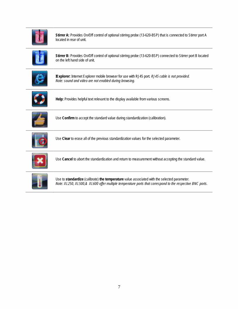
Stirrer A: Provides On/Off control of optional stirring probe (13-620-BSP) that is connected to Stirrer port A located in rear of unit.
Stirrer B: Provides On/Off control of optional stirring probe (13-620-BSP) connected to Stirrer port B located on the left hand side of unit.
IExplorer: Internet Explorer mobile browser for use with RJ45 port. RJ45 cable is not provided. Note: sound and video are not enabled during browsing.
Help: Provides helpful text relevant to the display available from various screens.
Use Confirm to accept the standard value during standardization (calibration).
Use Clear to erase all of the previous standardization values for the selected parameter.
Use Cancel to abort the standardization and return to measurement without accepting the standard value.
Use to standardize (calibrate) the temperature value associated with the selected parameter. Note: XL250, XL500,& XL600 offer multiple temperature ports that correspond to the respective BNC ports.
8
3. CONNECTIONS
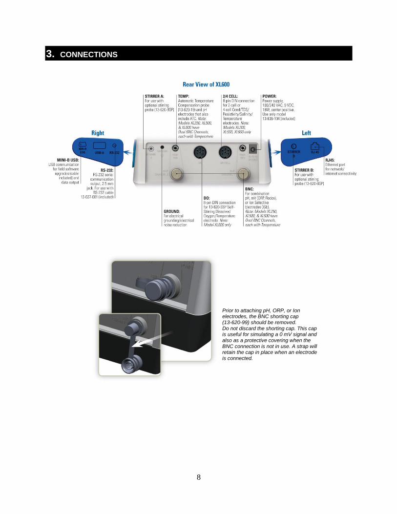
Prior to attaching pH, ORP, or Ion electrodes, the BNC shorting cap (13-620-99) should be removed. Do not discard the shorting cap. This cap is useful for simulating a 0 mV signal and also as a protective covering when the BNC connection is not in use. A strap will retain the cap in place when an electrode is connected.
9
4. ELECTRODE BRACKET & ARM ASSEMBLY
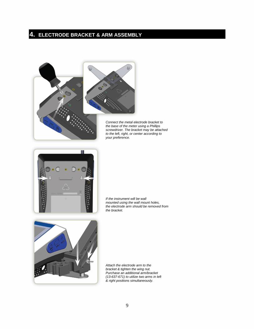
Connect the metal electrode bracket to the base of the meter using a Phillips screwdriver. The bracket may be attached to the left, right, or center according to your preference.
If the instrument will be wall mounted using the wall mount holes, the electrode arm should be removed from the bracket.
Attach the electrode arm to the bracket & tighten the wing nut. Purchase an additional arm/bracket (13-637-671) to utilize two arms in left & right positions simultaneously.
10
5. POWER ON/OFF
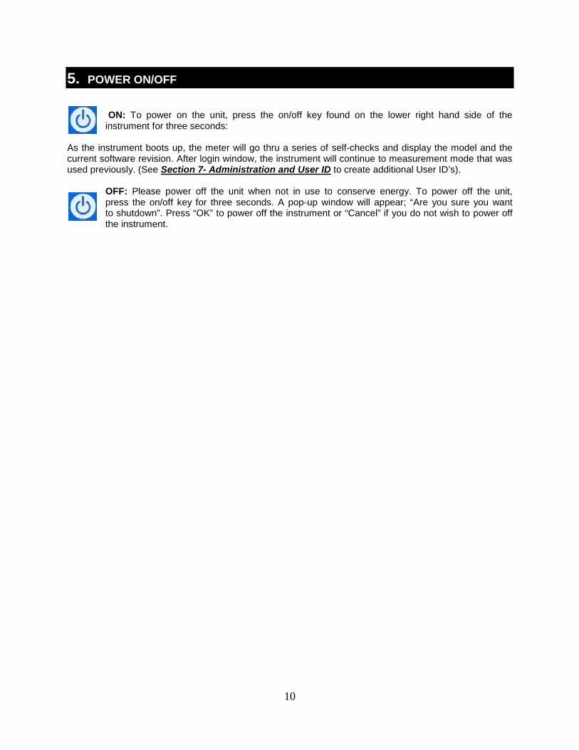
ON: To power on the unit, press the on/off key found on the lower right hand side of the
instrument for three seconds:
As the instrument boots up, the meter will go thru a series of self-checks and display the model and the current software revision. After login window, the instrument will continue to measurement mode that was used previously. (See Section 7- Administration and User ID
to create additional User ID’s).
OFF: Please power off the unit when not in use to conserve energy. To power off the unit, press the on/off key for three seconds. A pop-up window will appear; “Are you sure you want to shutdown”. Press “OK” to power off the instrument or “Cancel” if you do not wish to power off the instrument.
11
Tip: Check www.fishersci.com/accumet for free instrument software updates.
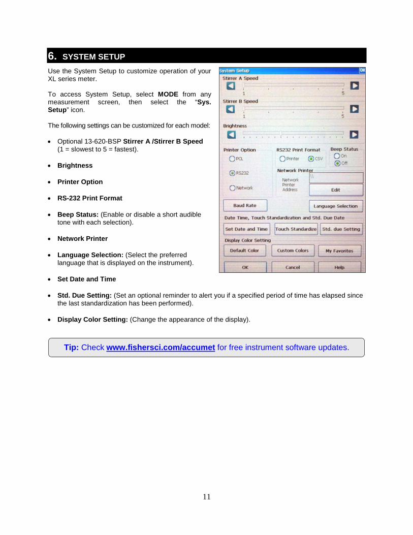
6. SYSTEM SETUP Use the System Setup to customize operation of your XL series meter. To access System Setup, select MODE from any measurement screen, then select the “Sys. Setup” icon. The following settings can be customized for each model: • Optional 13-620-BSP Stirrer A /Stirrer B Speed
(1 = slowest to 5 = fastest).
• Brightness
• Printer Option
• RS-232 Print Format
• Beep Status: (Enable or disable a short audible tone with each selection).
• Network Printer
• Language Selection: (Select the preferred language that is displayed on the instrument).
• Set Date and Time
• Std. Due Setting: (Set an optional reminder to alert you if a specified period of time has elapsed since the last standardization has been performed).
• Display Color Setting: (Change the appearance of the display).
12
7. ADMINISTRATION & USER ID Up to (10) unique User ID’s can be created. Alternatively, the factory default User ID login “Default” with no password protection can be used. Creation of a User ID is optional but can offer several advantages including: • Security: Password protection for each User ID.
• Separation: Keep stored data, settings, & standardization together.
• Detailed Data: Saved and printed includes the unique User ID setting.
• Reduce Setup and Standardization: Instead of using “Default”, create a department or application specific User ID, such as “LAB”, “QC”, “pH”, or “Test 123”. This will save significant setup time and also eliminate the need for new standardizations with each parameter change.
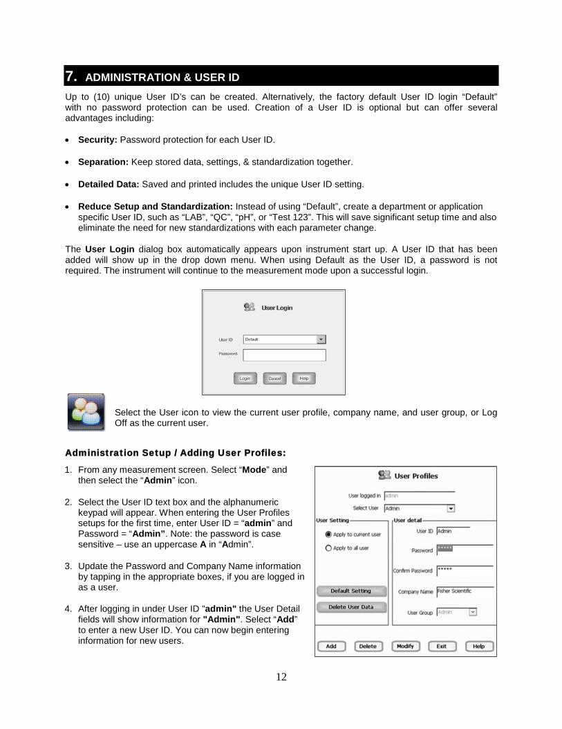
The User Login dialog box automatically appears upon instrument start up. A User ID that has been added will show up in the drop down menu. When using Default as the User ID, a password is not required. The instrument will continue to the measurement mode upon a successful login.
Select the User icon to view the current user profile, company name, and user group, or Log Off as the current user.
Administration Setup / Adding User Profiles:
1. From any measurement screen. Select “Mode” and then select the “Admin” icon.
2. Select the User ID text box and the alphanumeric keypad will appear. When entering the User Profiles setups for the first time, enter User ID = “admin” and Password = “Admin”. Note: the password is case sensitive – use an uppercase A in “Admin”.
3. Update the Password and Company Name information by tapping in the appropriate boxes, if you are logged in as a user.
4. After logging in under User ID "admin" the User Detail fields will show information for "Admin". Select “Add” to enter a new User ID. You can now begin entering information for new users.
13
5. Use the alphanumeric keypad to key in the new User ID. The User ID cannot exceed 10 characters. Press Enter to confirm.
6. Use the alphanumeric keypad to key in the Password. The password cannot exceed 12 characters. Press Enter to confirm.
7. Use the alphanumeric keypad to key in the Confirm Password field. Press Enter to confirm.
8. Use the alphanumeric keypad to key in the Company Name. Select OK when all changes have been made.
9. Select Add. A window will show "Are you sure, you want to add this user?" Select Yes or No. Select Yes to add the new user. Select No to continue editing the current user.
10. Upon successful addition of a new user ID, the instrument will show “User has been added successfully”. Select “OK”.
11. Select Exit when finished. A message “User profile saved. Meter will reboot now” will appear. Select “OK”. The instrument will restart and the newly created User ID(s) will be available.
Function Keys From User Profiles Screen:
• Add: To add a new User ID.
• Delete: To delete the user ID.
• Modify: Modify the current user details.
• Exit: To exit User Profile Screen. Reboot is automatic after adding new User ID or making changes to an existing user.
• Apply To Current User: To apply Default Setting or Delete User Data function buttons to current user only.
• Apply To All User: To apply Default Setting or Delete User Data function buttons to all users.
• Default Setting: To reset current or all users to factory default setting of meter.
• Delete User Data: To delete all measurement data for current or all users.
14
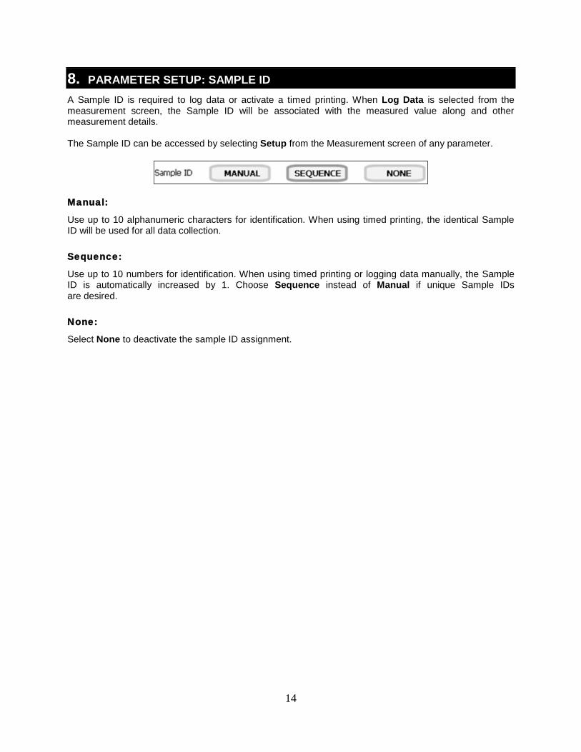
8. PARAMETER SETUP: SAMPLE ID A Sample ID is required to log data or activate a timed printing. When Log Data is selected from the measurement screen, the Sample ID will be associated with the measured value along and other measurement details. The Sample ID can be accessed by selecting Setup from the Measurement screen of any parameter. Manual:
Use up to 10 alphanumeric characters for identification. When using timed printing, the identical Sample ID will be used for all data collection. Sequence:
Use up to 10 numbers for identification. When using timed printing or logging data manually, the Sample ID is automatically increased by 1. Choose Sequence instead of Manual if unique Sample IDs are desired. None:
Select None to deactivate the sample ID assignment.
15
Tip: Take caution when using AUTO; if accidentally selected, it may seem like the electrode or meter is un-responsive when in fact the measurement is locked and
selecting “Measure” screen is the only way to get the current reading to re-appear.
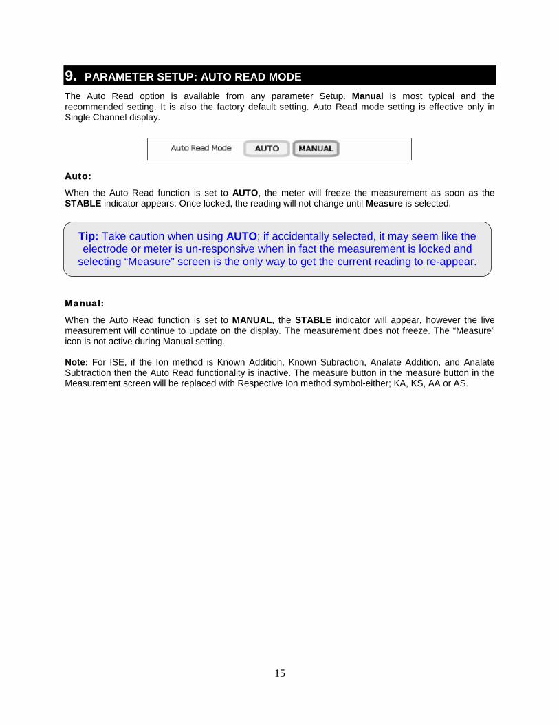
9. PARAMETER SETUP: AUTO READ MODE The Auto Read option is available from any parameter Setup. Manual is most typical and the recommended setting. It is also the factory default setting. Auto Read mode setting is effective only in Single Channel display.
Auto:
When the Auto Read function is set to AUTO, the meter will freeze the measurement as soon as the STABLE indicator appears. Once locked, the reading will not change until Measure is selected.
Manual:
When the Auto Read function is set to MANUAL, the STABLE indicator will appear, however the live measurement will continue to update on the display. The measurement does not freeze. The “Measure” icon is not active during Manual setting. Note: For ISE, if the Ion method is Known Addition, Known Subraction, Analate Addition, and Analate Subtraction then the Auto Read functionality is inactive. The measure button in the measure button in the Measurement screen will be replaced with Respective Ion method symbol-either; KA, KS, AA or AS.
16
Tip: Select a lower pH resolution such as X.XX instead of X.XXX to decrease stabilization time.
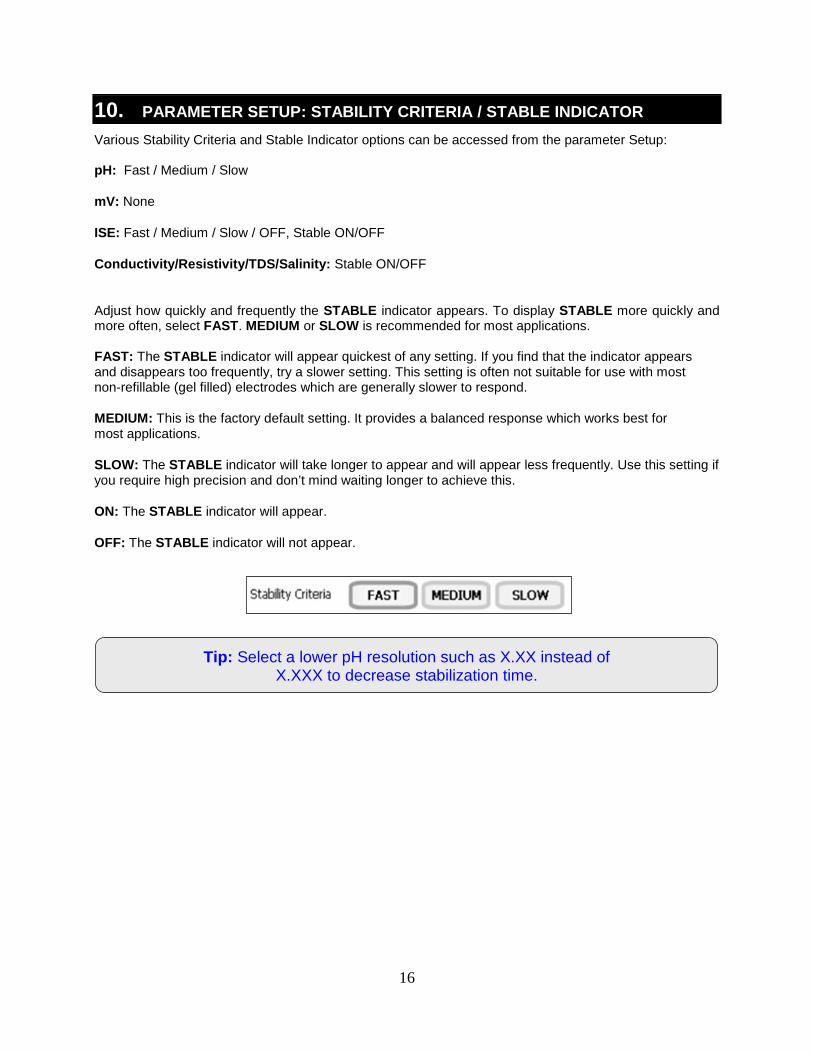
10. PARAMETER SETUP: STABILITY CRITERIA / STABLE INDICATOR Various Stability Criteria and Stable Indicator options can be accessed from the parameter Setup: pH: Fast / Medium / Slow
mV: None
ISE: Fast / Medium / Slow / OFF, Stable ON/OFF
Conductivity/Resistivity/TDS/Salinity: Stable ON/OFF
Adjust how quickly and frequently the STABLE indicator appears. To display STABLE more quickly and more often, select FAST. MEDIUM or SLOW is recommended for most applications. FAST: The STABLE indicator will appear quickest of any setting. If you find that the indicator appears and disappears too frequently, try a slower setting. This setting is often not suitable for use with most non-refillable (gel filled) electrodes which are generally slower to respond.
MEDIUM: This is the factory default setting. It provides a balanced response which works best for most applications.
SLOW: The STABLE indicator will take longer to appear and will appear less frequently. Use this setting if you require high precision and don’t mind waiting longer to achieve this.
ON: The STABLE indicator will appear.
OFF: The STABLE indicator will not appear.
17
Tip: Using an ATC probe will override any value entered in the default temperature screen.
The measured temperature will be used by the meter to determine the pH reading.
11. PARAMETER SETUP: DEFAULT TEMPERATURE To eliminate temperature errors associated with the pH electrode, attach an automatic temperature compensation (ATC) probe for best accuracy. Without temperature compensation, pH accuracy will decrease as samples deviate from 25 ºC and pH 7. The factory default setting is 25 °C / 77 °F. If you are not using an ATC probe or the ATC is removed from the meter, the default temperature will be used instead. The default temperature range is -10 °C to 110 °C. If you are measuring the pH of a solution that is not 25 °C and you are not using an Automatic Temperature Compensation (ATC) probe, enter the temperature value of the solution for best results. The manual temperature compensation (MTC) value will be visible on the screen. The default temperature can be set from -5 °C to 105 °C.
To Set Default Temperature:
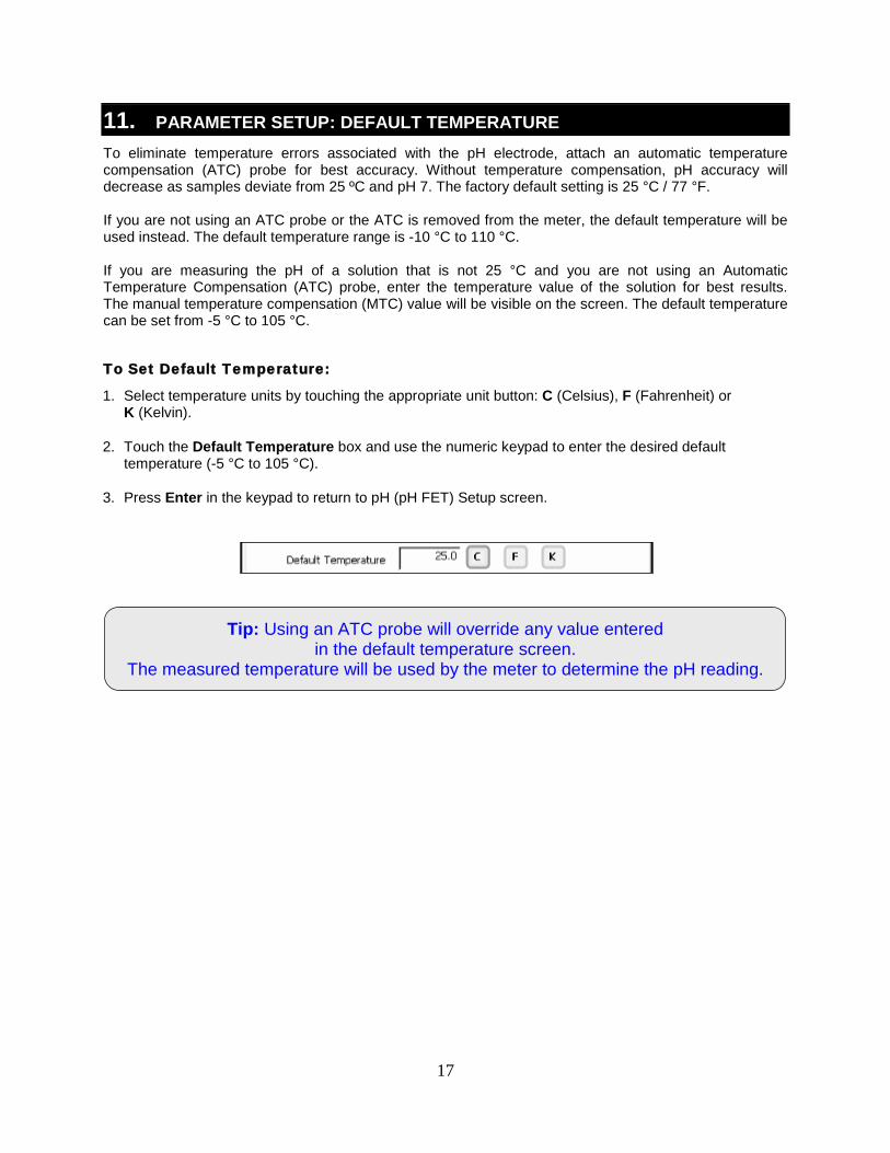
1. Select temperature units by touching the appropriate unit button: C (Celsius), F (Fahrenheit) or K (Kelvin).
2. Touch the Default Temperature box and use the numeric keypad to enter the desired default temperature (-5 °C to 105 °C).
3. Press Enter in the keypad to return to pH (pH FET) Setup screen.
18
12. PARAMETER SETUP: ISOPOTENTIAL POINT The isopotential point is the millivolt reading for an electrode at which temperature has no effect on the measurement. Electrodes for pH measurement are constructed so that the isopotential point is theoretically zero millivolts. Most pH electrodes do not achieve this value precisely. However they are close enough so that it is not usually necessary to use an isopotential point other than zero. The true isopotential point of any given electrode must be determined experimentally. The isopotential point can be set from -100 to +100. To Set Isopotential Point:
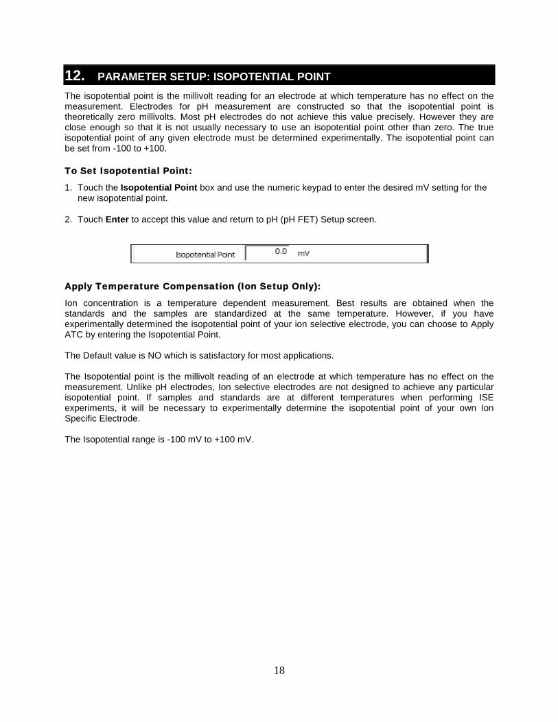
1. Touch the Isopotential Point box and use the numeric keypad to enter the desired mV setting for the new isopotential point.
2. Touch Enter to accept this value and return to pH (pH FET) Setup screen.
Apply Temperature Compensation (Ion Setup Only):
Ion concentration is a temperature dependent measurement. Best results are obtained when the standards and the samples are standardized at the same temperature. However, if you have experimentally determined the isopotential point of your ion selective electrode, you can choose to Apply ATC by entering the Isopotential Point. The Default value is NO which is satisfactory for most applications. The Isopotential point is the millivolt reading of an electrode at which temperature has no effect on the measurement. Unlike pH electrodes, Ion selective electrodes are not designed to achieve any particular isopotential point. If samples and standards are at different temperatures when performing ISE experiments, it will be necessary to experimentally determine the isopotential point of your own Ion Specific Electrode. The Isopotential range is -100 mV to +100 mV.
19
13. PARAMETER SETUP: ALARM LIMITS The High and Low Alarm Limits are available from any parameter Setup. Select an Alarm Limit to enable a visual and audible alarm to alert you whenever a High or Low value is exceeded. When a measurement exceeds the Alarm limit, a corresponding “HI ALARM” or “LOW ALARM” will blink on the display while simultaneously producing a loud, intermittent beep
. The alarm will continue until the conditions are no longer met, and will only be active during measurement mode.
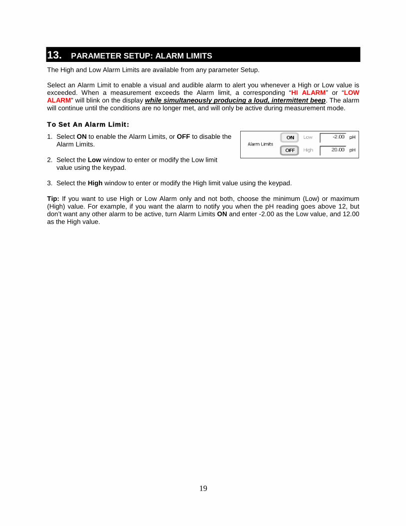
To Set An Alarm Limit:
1. Select ON to enable the Alarm Limits, or OFF to disable the Alarm Limits.
2. Select the Low window to enter or modify the Low limit value using the keypad.
3. Select the High window to enter or modify the High limit value using the keypad.
Tip: If you want to use High or Low Alarm only and not both, choose the minimum (Low) or maximum (High) value. For example, if you want the alarm to notify you when the pH reading goes above 12, but don’t want any other alarm to be active, turn Alarm Limits ON and enter -2.00 as the Low value, and 12.00 as the High value.
20
14. PARAMETER SETUP: PRINT CRITERIA The Print Criteria setting is available from any parameter Setup. Use this option to select which criteria are printed along with the measurement when you print the data. To Set Print Criteria:
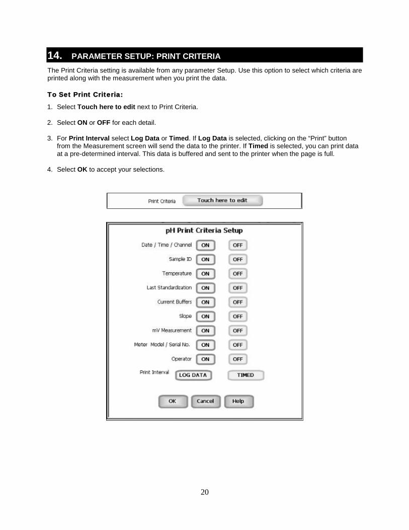
1. Select Touch here to edit next to Print Criteria.
2. Select ON or OFF for each detail.
3. For Print Interval select Log Data or Timed. If Log Data is selected, clicking on the “Print” button from the Measurement screen will send the data to the printer. If Timed is selected, you can print data at a pre-determined interval. This data is buffered and sent to the printer when the page is full.
4. Select OK to accept your selections.
21
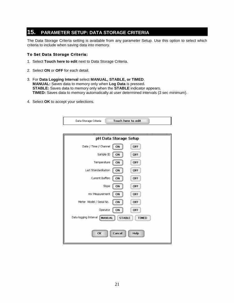
15. PARAMETER SETUP: DATA STORAGE CRITERIA The Data Storage Criteria setting is available from any parameter Setup. Use this option to select which criteria to include when saving data into memory. To Set Data Storage Criteria:
1. Select Touch here to edit next to Data Storage Criteria.
2. Select ON or OFF for each detail.
3. For Data Logging Interval select MANUAL, STABLE, or TIMED. MANUAL: Saves data to memory only when Log Data is pressed. STABLE: Saves data to memory only when the STABLE indicator appears. TIMED: Saves data to memory automatically at user determined intervals (3 sec minimum).
4. Select OK to accept your selections.
22
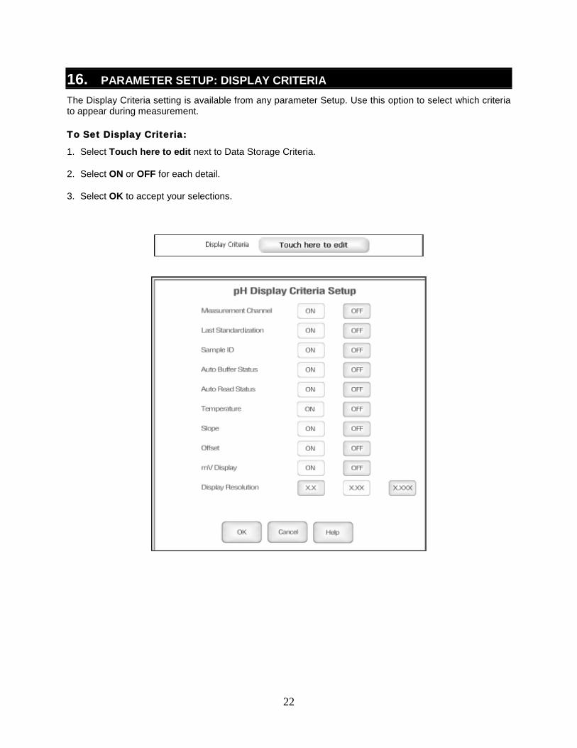
16. PARAMETER SETUP: DISPLAY CRITERIA The Display Criteria setting is available from any parameter Setup. Use this option to select which criteria to appear during measurement. To Set Display Criteria:
1. Select Touch here to edit next to Data Storage Criteria.
2. Select ON or OFF for each detail.
3. Select OK to accept your selections.
23
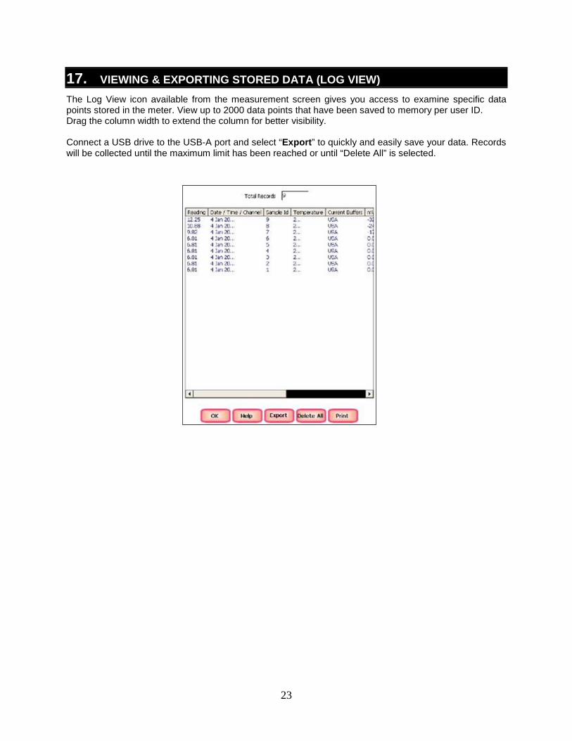
17. VIEWING & EXPORTING STORED DATA (LOG VIEW) The Log View icon available from the measurement screen gives you access to examine specific data points stored in the meter. View up to 2000 data points that have been saved to memory per user ID. Drag the column width to extend the column for better visibility. Connect a USB drive to the USB-A port and select “Export” to quickly and easily save your data. Records will be collected until the maximum limit has been reached or until “Delete All” is selected.
24
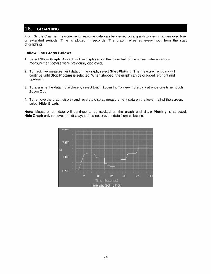
18. GRAPHING From Single Channel measurement, real-time data can be viewed on a graph to view changes over brief or extended periods. Time is plotted in seconds. The graph refreshes every hour from the start of graphing. Follow The Steps Below:
1. Select Show Graph. A graph will be displayed on the lower half of the screen where various measurement details were previously displayed.
2. To track live measurement data on the graph, select Start Plotting. The measurement data will continue until Stop Plotting is selected. When stopped, the graph can be dragged left/right and up/down.
3. To examine the data more closely, select touch Zoom In. To view more data at once one time, touch Zoom Out.
4. To remove the graph display and revert to display measurement data on the lower half of the screen, select Hide Graph.
Note: Measurement data will continue to be tracked on the graph until Stop Plotting is selected. Hide Graph only removes the display; it does not prevent data from collecting.
25
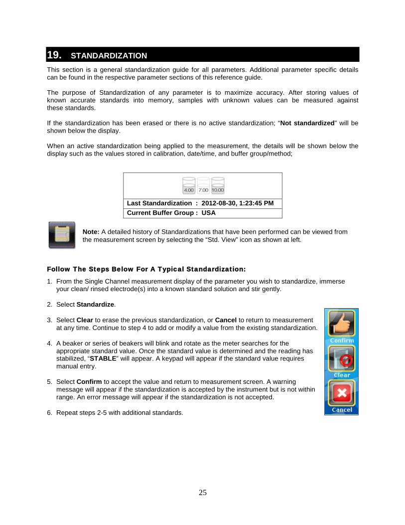
19. STANDARDIZATION This section is a general standardization guide for all parameters. Additional parameter specific details can be found in the respective parameter sections of this reference guide. The purpose of Standardization of any parameter is to maximize accuracy. After storing values of known accurate standards into memory, samples with unknown values can be measured against these standards. If the standardization has been erased or there is no active standardization; “Not standardized” will be shown below the display. When an active standardization being applied to the measurement, the details will be shown below the display such as the values stored in calibration, date/time, and buffer group/method;
Last Standardization : 2012-08-30, 1:23:45 PM Current Buffer Group : USA
Note: A detailed history of Standardizations that have been performed can be viewed from the measurement screen by selecting the “Std. View” icon as shown at left.
Follow The Steps Below For A Typical Standardization:
1. From the Single Channel measurement display of the parameter you wish to standardize, immerse your clean/ rinsed electrode(s) into a known standard solution and stir gently.
2. Select Standardize.
3. Select Clear to erase the previous standardization, or Cancel to return to measurement at any time. Continue to step 4 to add or modify a value from the existing standardization.
4. A beaker or series of beakers will blink and rotate as the meter searches for the appropriate standard value. Once the standard value is determined and the reading has stabilized, “STABLE” will appear. A keypad will appear if the standard value requires manual entry.
5. Select Confirm to accept the value and return to measurement screen. A warning message will appear if the standardization is accepted by the instrument but is not within range. An error message will appear if the standardization is not accepted.
6. Repeat steps 2-5 with additional standards.
26
Ion Operation: Incremental Methods XL25, 50 and 60 meters
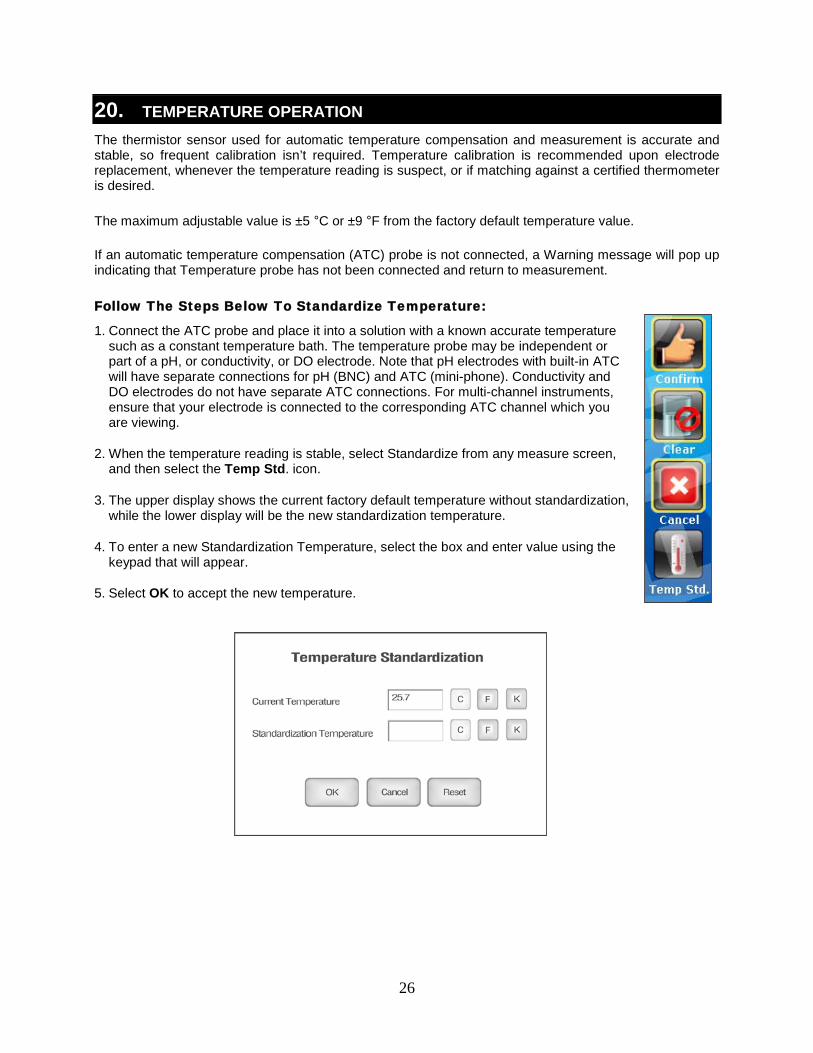
20. TEMPERATURE OPERATION The thermistor sensor used for automatic temperature compensation and measurement is accurate and stable, so frequent calibration isn’t required. Temperature calibration is recommended upon electrode replacement, whenever the temperature reading is suspect, or if matching against a certified thermometer is desired. The maximum adjustable value is ±5 °C or ±9 °F from the factory default temperature value. If an automatic temperature compensation (ATC) probe is not connected, a Warning message will pop up indicating that Temperature probe has not been connected and return to measurement. Follow The Steps Below To Standardize Temperature:
1. Connect the ATC probe and place it into a solution with a known accurate temperature such as a constant temperature bath. The temperature probe may be independent or part of a pH, or conductivity, or DO electrode. Note that pH electrodes with built-in ATC will have separate connections for pH (BNC) and ATC (mini-phone). Conductivity and DO electrodes do not have separate ATC connections. For multi-channel instruments, ensure that your electrode is connected to the corresponding ATC channel which you are viewing.
2. When the temperature reading is stable, select Standardize from any measure screen, and then select the Temp Std. icon.
3. The upper display shows the current factory default temperature without standardization, while the lower display will be the new standardization temperature.
4. To enter a new Standardization Temperature, select the box and enter value using the keypad that will appear.
5. Select OK to accept the new temperature.
27
Ion Operation: Incremental Methods XL25, 50 and 60 meters
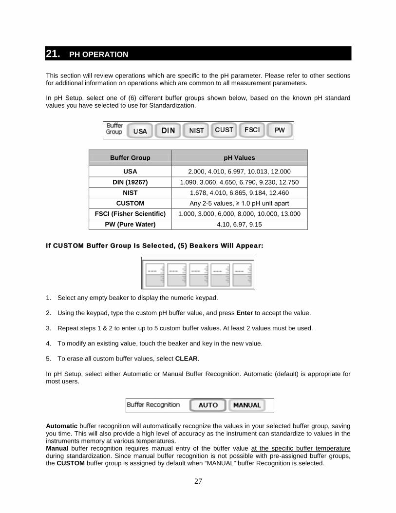
21. PH OPERATION This section will review operations which are specific to the pH parameter. Please refer to other sections for additional information on operations which are common to all measurement parameters. In pH Setup, select one of (6) different buffer groups shown below, based on the known pH standard values you have selected to use for Standardization.
Buffer Group pH Values
USA 2.000, 4.010, 6.997, 10.013, 12.000 DIN (19267) 1.090, 3.060, 4.650, 6.790, 9.230, 12.750
NIST 1.678, 4.010, 6.865, 9.184, 12.460 CUSTOM Any 2-5 values, ≥ 1.0 pH unit apart
FSCI (Fisher Scientific) 1.000, 3.000, 6.000, 8.000, 10.000, 13.000 PW (Pure Water) 4.10, 6.97, 9.15
If CUSTOM Buffer Group Is Selected, (5) Beakers Will Appear:
1. Select any empty beaker to display the numeric keypad.
2. Using the keypad, type the custom pH buffer value, and press Enter to accept the value.
3. Repeat steps 1 & 2 to enter up to 5 custom buffer values. At least 2 values must be used.
4. To modify an existing value, touch the beaker and key in the new value.
5. To erase all custom buffer values, select CLEAR.
In pH Setup, select either Automatic or Manual Buffer Recognition. Automatic (default) is appropriate for most users. Automatic buffer recognition will automatically recognize the values in your selected buffer group, saving you time. This will also provide a high level of accuracy as the instrument can standardize to values in the instruments memory at various temperatures. Manual buffer recognition requires manual entry of the buffer value at the specific buffer temperature during standardization. Since manual buffer recognition is not possible with pre-assigned buffer groups, the CUSTOM buffer group is assigned by default when “MANUAL” buffer Recognition is selected.
28
Ion Operation: Incremental Methods XL25, 50 and 60 meters
pH Standardization Notes:
For best results, periodic standardization (calibration) with known accurate standards is recommended prior to measurement. Use standards that bracket your intended measuring range while including a neutral point (7.00, 6.86, or 6.79). For example, if you expect to measure samples from pH 6.2 to 9.5, calibration with 4.01, 7.00, and 10.01 will work well. Do not reuse buffer solutions after calibration. Verify the pH and ATC electrodes connected to the meter in Channel 1 or Channel 2 correspond to the respective measurement channel on the display. To eliminate temperature errors associated with the pH electrode, attach the automatic temperature compensation (ATC) probe for best accuracy. Without temperature compensation, pH accuracy will decrease as samples deviate from 25 ºC and pH 7 or 0 mV. If the pH electrode has been stored dry, soak in storage solution for 10 minutes before standardization to saturate the pH electrode surface and minimize drift. If storage solution is not available, use a neutral pH buffer. While OK for rinsing, do not store pH electrodes in deionized or distilled water as this will dehydrate the electrode and decrease performance. The efficiency of the electrode is reported as the slope. Slope can be described as percentage where 100 % is ideal, or as a mV/decade unit. When performing standardization with 3 or more standards, multiple slopes will be calculated by the instrument. The slope that appears on the screen during measurement, is the slope which is applicable to the zone in which the measurement is currently being made. For example, if pH 4, 7, and 10 are standardized, and a sample of pH 5 is being measured, the slope displayed would be the slope calculated between 4 and 7. The slopes are independent of each other. If Auto Read function is "ON", the meter will freeze the measurement as soon as the STABLE indicator appears. Once locked, the reading will not change until Measure is selected. Do not reuse buffer solutions after calibration – especially pH 10 which drifts with prolonged exposure to air. Check to ensure that the reference junction of the electrode is not clogged, the reference fill solution is not contaminated or discolored, and the electrode has a proper level of the correct filling solution appropriate for the electrode used. Any of these conditions can lead to erratic or drifting measurements. Avoid prolonged exposure of the pH glass to alkaline, organic, surfactant and hydrofluoric acid solutions. Each of these will deteriorate the pH response of the glass. After measurement, remove the electrode from the sample rinse with clean water, and place the electrode into your storage solution. If immersed in solution, the fill-hole of the refillable electrode should be uncovered in the open position to prevent proper electrolyte flow. When possible, provide stirring to the standards and samples. This speeds up the response, and permits a more representative measurement. Do not wipe the electrode. This may impart a static charge, and result in an unstable reading. A hydrated electrode is important – rinse and shake dry without wiping.
29
Ion Operation: Incremental Methods XL25, 50 and 60 meters
22. MILLIVOLT OPERATION This mode is used to measure oxidation/ reduction potential (ORP/Redox), perform titration, and to verify the function of the meter. The mV measure function allows you to continuously monitor the mV potential of the electrodes in use. This can be done in either absolute (abs) or relative mV (Rel mV). In millivolt mode, the current millivolt output from the electrodes being used is monitored and displayed on the screen. The meter will continually monitor the millivolts reading in this mode and will not lock onto a single reading. However, once the reading has become stable, the STABLE indicator will appear. Relative mV Standardization:
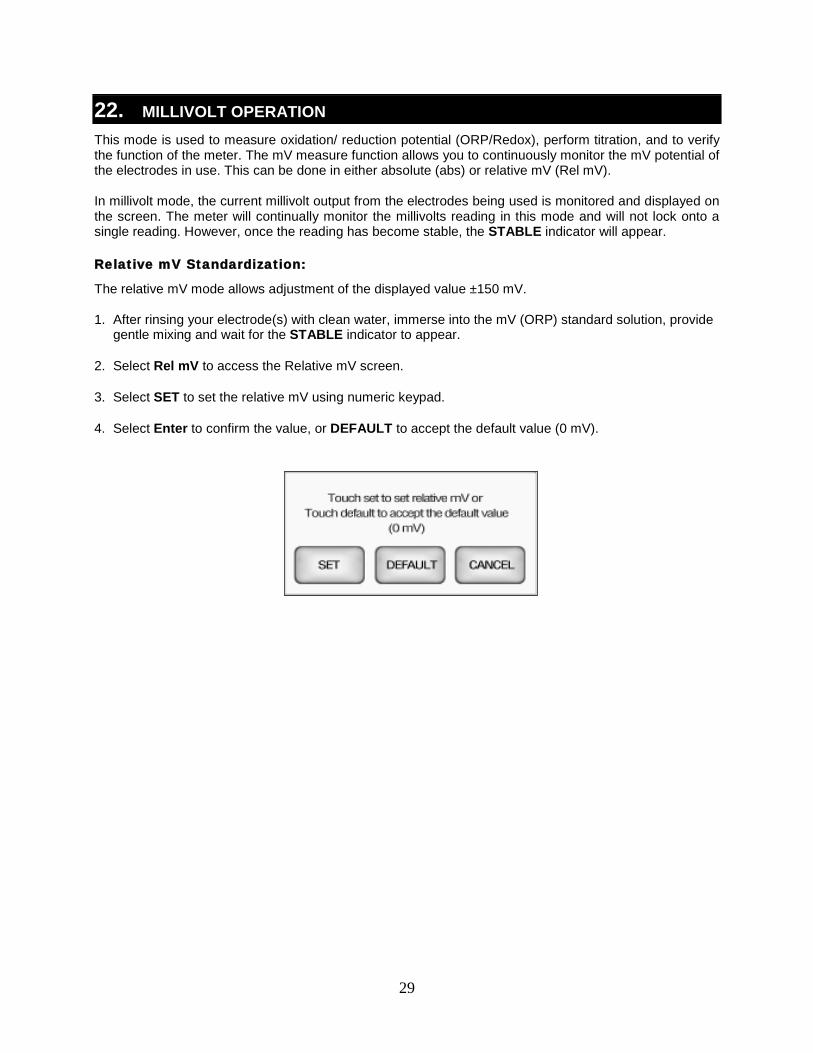
The relative mV mode allows adjustment of the displayed value ±150 mV. 1. After rinsing your electrode(s) with clean water, immerse into the mV (ORP) standard solution, provide
gentle mixing and wait for the STABLE indicator to appear.
2. Select Rel mV to access the Relative mV screen.
3. Select SET to set the relative mV using numeric keypad.
4. Select Enter to confirm the value, or DEFAULT to accept the default value (0 mV).
30
Ion Operation: Incremental Methods XL25, 50 and 60 meters
23. ION: SETUP & OPERATION Refer to your Ion Selective Electrode instruction manual for details on conditioning, storage, maintenance, calibration standard preparation, Ionic Strength Adjustment, troubleshooting, etc. Each ISE is unique and requires care and operation that is specific to the electrode and ion of interest. Ion Method:
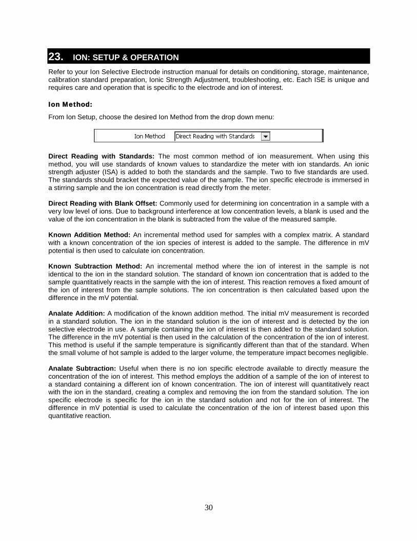
From Ion Setup, choose the desired Ion Method from the drop down menu: Direct Reading with Standards: The most common method of ion measurement. When using this method, you will use standards of known values to standardize the meter with ion standards. An ionic strength adjuster (ISA) is added to both the standards and the sample. Two to five standards are used. The standards should bracket the expected value of the sample. The ion specific electrode is immersed in a stirring sample and the ion concentration is read directly from the meter. Direct Reading with Blank Offset: Commonly used for determining ion concentration in a sample with a very low level of ions. Due to background interference at low concentration levels, a blank is used and the value of the ion concentration in the blank is subtracted from the value of the measured sample. Known Addition Method: An incremental method used for samples with a complex matrix. A standard with a known concentration of the ion species of interest is added to the sample. The difference in mV potential is then used to calculate ion concentration. Known Subtraction Method: An incremental method where the ion of interest in the sample is not identical to the ion in the standard solution. The standard of known ion concentration that is added to the sample quantitatively reacts in the sample with the ion of interest. This reaction removes a fixed amount of the ion of interest from the sample solutions. The ion concentration is then calculated based upon the difference in the mV potential. Analate Addition: A modification of the known addition method. The initial mV measurement is recorded in a standard solution. The ion in the standard solution is the ion of interest and is detected by the ion selective electrode in use. A sample containing the ion of interest is then added to the standard solution. The difference in the mV potential is then used in the calculation of the concentration of the ion of interest. This method is useful if the sample temperature is significantly different than that of the standard. When the small volume of hot sample is added to the larger volume, the temperature impact becomes negligible. Analate Subtraction: Useful when there is no ion specific electrode available to directly measure the concentration of the ion of interest. This method employs the addition of a sample of the ion of interest to a standard containing a different ion of known concentration. The ion of interest will quantitatively react with the ion in the standard, creating a complex and removing the ion from the standard solution. The ion specific electrode is specific for the ion in the standard solution and not for the ion of interest. The difference in mV potential is used to calculate the concentration of the ion of interest based upon this quantitative reaction.
31
Ion Operation: Incremental Methods XL25, 50 and 60 meters
Tip: If you will use multiple ISE electrodes, it is a good idea to create a different User ID for each electrode used, Such as User ID = “Ammonia”,
“Fluoride”, or “Na K” if you are testing two channels for Sodium and Potassium simultaneously. This will retain the individual parameter settings,
calibration information, and stored data together.
Electrode Type:
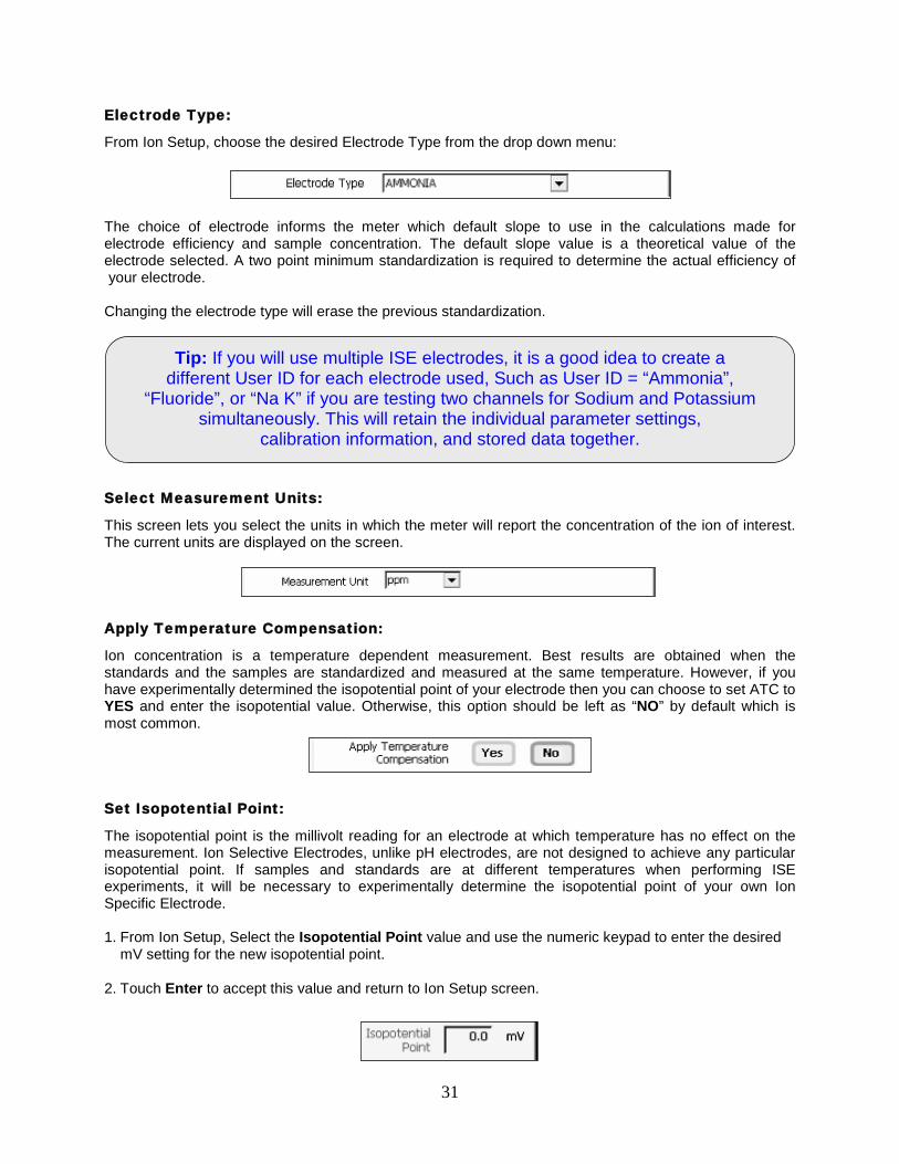
From Ion Setup, choose the desired Electrode Type from the drop down menu: The choice of electrode informs the meter which default slope to use in the calculations made for electrode efficiency and sample concentration. The default slope value is a theoretical value of the electrode selected. A two point minimum standardization is required to determine the actual efficiency of your electrode. Changing the electrode type will erase the previous standardization.
Select Measurement Units:
This screen lets you select the units in which the meter will report the concentration of the ion of interest. The current units are displayed on the screen.
Apply Temperature Compensation:
Ion concentration is a temperature dependent measurement. Best results are obtained when the standards and the samples are standardized and measured at the same temperature. However, if you have experimentally determined the isopotential point of your electrode then you can choose to set ATC to YES and enter the isopotential value. Otherwise, this option should be left as “NO” by default which is most common.
Set Isopotential Point:
The isopotential point is the millivolt reading for an electrode at which temperature has no effect on the measurement. Ion Selective Electrodes, unlike pH electrodes, are not designed to achieve any particular isopotential point. If samples and standards are at different temperatures when performing ISE experiments, it will be necessary to experimentally determine the isopotential point of your own Ion Specific Electrode. 1. From Ion Setup, Select the Isopotential Point value and use the numeric keypad to enter the desired
mV setting for the new isopotential point.
2. Touch Enter to accept this value and return to Ion Setup screen.
32
Ion Operation: Incremental Methods XL25, 50 and 60 meters
Tip: The STABLE indicator will only appear upon completion of a successful two point standardization. If the meter has not been standardized with at least two
standards, a series of dashes will appear in place of a measurement value.
24. ION: DIRECT READING METHODS There are two direct reading methods – Direct Reading with Standards and Direct Reading with Blank Offset. These types of measurements allow you to directly read the concentration of your sample after standardizing the meter with ion standards of known values or blank values. Direct Reading With Standards:
This is the most common method of ion measurement. You can directly read the concentration of the sample after standardizing the meter with known ion standard solutions. An ionic strength adjuster (ISA) is added to both the standards and the sample. The standards should bracket the expected value of the sample. You must use a minimum of two standards to standardize the meter. For best results always begin with your lowest calibration standard value, followed by the next lowest, and so on. 1. Rinse and immerse your clean Ion selective electrode which has been prepared according to the
electrode instruction manual into a known standard solution and stir gently.
2. Select the Standardize icon. "Clear" will delete the previous standardization values and "Cancel" will return to measurement mode.
3. A keypad will open after one scanning cycle. Using the displayed keypad, input the value of the known standard solution you are using and press "ENTER".
4. The meter will show the value which can be seen blinking on the display.
5. Wait for the reading to stabilize (Tip: observe the millivolt value). When stable, select “Confirm” to accept the standardization.
6. Repeat steps 1-5 with additional ion standards.
Direct Reading With Blank Offset:
This method is useful for measuring samples with low level concentrations of selected ion of interest. It eliminates background interference by subtracting the value of a blank concentration from the value of the sample. You must use a minimum of one blank and two standards for this method. For best results always begin with your blank, followed by your lowest calibration standard value, followed by the next lowest, and so on. 1. Add ionic strength adjuster as needed to the calibration standards and the blank.
2. Rinse and immerse your clean Ion selective electrode which has been prepared according to the electrode instruction manual into your solution blank or lowest calibration standard value and stir gently.
3. Select the Standardize icon. "Clear" will delete the previous standardization values and "Cancel" will return to measurement mode.
33
Ion Operation: Incremental Methods XL25, 50 and 60 meters
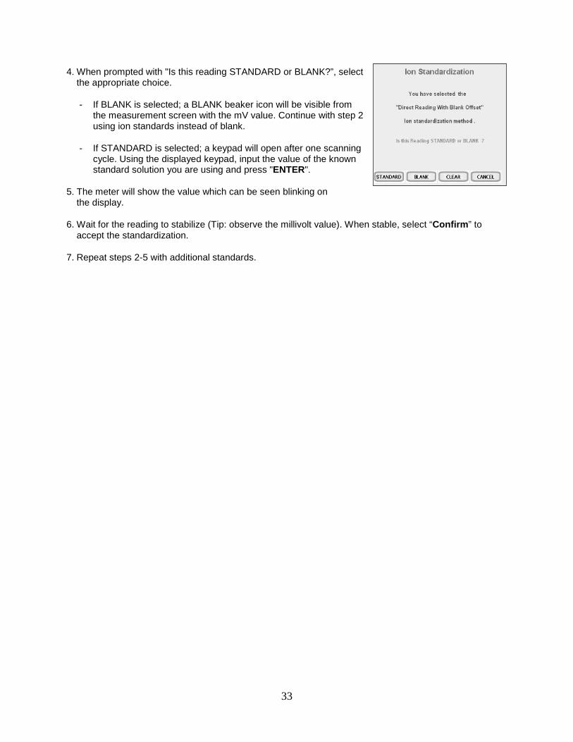
4. When prompted with "Is this reading STANDARD or BLANK?”, select the appropriate choice.
- If BLANK is selected; a BLANK beaker icon will be visible from the measurement screen with the mV value. Continue with step 2 using ion standards instead of blank.
- If STANDARD is selected; a keypad will open after one scanning cycle. Using the displayed keypad, input the value of the known standard solution you are using and press "ENTER".
5. The meter will show the value which can be seen blinking on the display.
6. Wait for the reading to stabilize (Tip: observe the millivolt value). When stable, select “Confirm” to accept the standardization.
7. Repeat steps 2-5 with additional standards.
34
Ion Operation: Incremental Methods XL25, 50 and 60 meters
25. ION: INCREMENTAL METHODS The incremental methods which include known addition, known subtraction, analate addition and analate subtraction are particularly useful with samples containing complex ionic backgrounds which cannot be matched in standards. They are also useful with occasional samples whose temperatures vary. Standardizing The Meter For All Incremental Methods:
Prior to conducting an analysis using any of the incremental methods, it is necessary to standardize the meter with at least two standards. This will establish a slope value for the electrode in use. The slope value is required in the incremental method calculations which yield the ion concentration of the sample. Make sure you have selected one of the incremental methods (known addition, known subtraction, analate addition, or analate subtraction) in the Ion Setup screen.
35
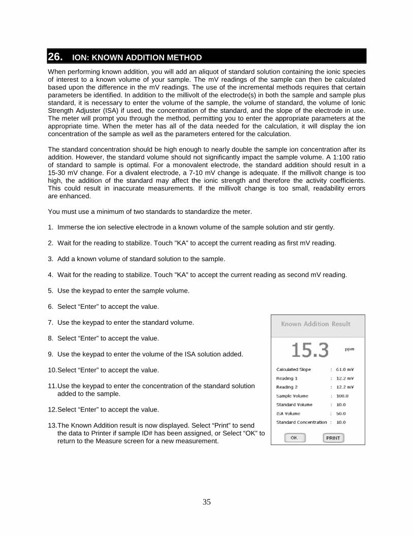
26. ION: KNOWN ADDITION METHOD When performing known addition, you will add an aliquot of standard solution containing the ionic species of interest to a known volume of your sample. The mV readings of the sample can then be calculated based upon the difference in the mV readings. The use of the incremental methods requires that certain parameters be identified. In addition to the millivolt of the electrode(s) in both the sample and sample plus standard, it is necessary to enter the volume of the sample, the volume of standard, the volume of Ionic Strength Adjuster (ISA) if used, the concentration of the standard, and the slope of the electrode in use. The meter will prompt you through the method, permitting you to enter the appropriate parameters at the appropriate time. When the meter has all of the data needed for the calculation, it will display the ion concentration of the sample as well as the parameters entered for the calculation. The standard concentration should be high enough to nearly double the sample ion concentration after its addition. However, the standard volume should not significantly impact the sample volume. A 1:100 ratio of standard to sample is optimal. For a monovalent electrode, the standard addition should result in a 15-30 mV change. For a divalent electrode, a 7-10 mV change is adequate. If the millivolt change is too high, the addition of the standard may affect the ionic strength and therefore the activity coefficients. This could result in inaccurate measurements. If the millivolt change is too small, readability errors are enhanced. You must use a minimum of two standards to standardize the meter. 1. Immerse the ion selective electrode in a known volume of the sample solution and stir gently.
2. Wait for the reading to stabilize. Touch "KA" to accept the current reading as first mV reading.
3. Add a known volume of standard solution to the sample.
4. Wait for the reading to stabilize. Touch "KA" to accept the current reading as second mV reading.
5. Use the keypad to enter the sample volume.
6. Select “Enter” to accept the value.
7. Use the keypad to enter the standard volume.
8. Select “Enter” to accept the value.
9. Use the keypad to enter the volume of the ISA solution added.
10. Select “Enter” to accept the value.
11. Use the keypad to enter the concentration of the standard solution added to the sample.
12. Select “Enter” to accept the value.
13. The Known Addition result is now displayed. Select “Print” to send the data to Printer if sample ID# has been assigned, or Select “OK” to return to the Measure screen for a new measurement.
36
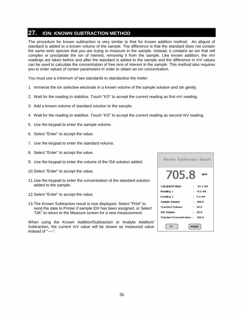
27. ION: KNOWN SUBTRACTION METHOD The procedure for known subtraction is very similar to that for known addition method. An aliquot of standard is added to a known volume of the sample. The difference is that the standard does not contain the same ionic species that you are trying to measure in the sample. Instead, it contains an ion that will complex or precipitate the ion of interest, removing it from the sample. Like known addition, the mV readings are taken before and after the standard is added to the sample and the difference in mV values can be used to calculate the concentration of free ions of interest in the sample. This method also requires you to enter values of certain parameters in order to obtain an ion concentration. You must use a minimum of two standards to standardize the meter. 1. Immerse the ion selective electrode in a known volume of the sample solution and stir gently.
2. Wait for the reading to stabilize. Touch "KS" to accept the current reading as first mV reading.
3. Add a known volume of standard solution to the sample.
4. Wait for the reading to stabilize. Touch "KS" to accept the current reading as second mV reading.
5. Use the keypad to enter the sample volume.
6. Select “Enter” to accept the value.
7. Use the keypad to enter the standard volume.
8. Select “Enter” to accept the value.
9. Use the keypad to enter the volume of the ISA solution added.
10. Select “Enter” to accept the value.
11. Use the keypad to enter the concentration of the standard solution added to the sample.
12. Select “Enter” to accept the value.
13. The Known Subtraction result is now displayed. Select “Print” to send the data to Printer if sample ID# has been assigned, or Select “OK” to return to the Measure screen for a new measurement.
When using the Known Addition/Subtraction or Analyte Addition/ Subtraction, the current mV value will be shown as measured value instead of "----".
37
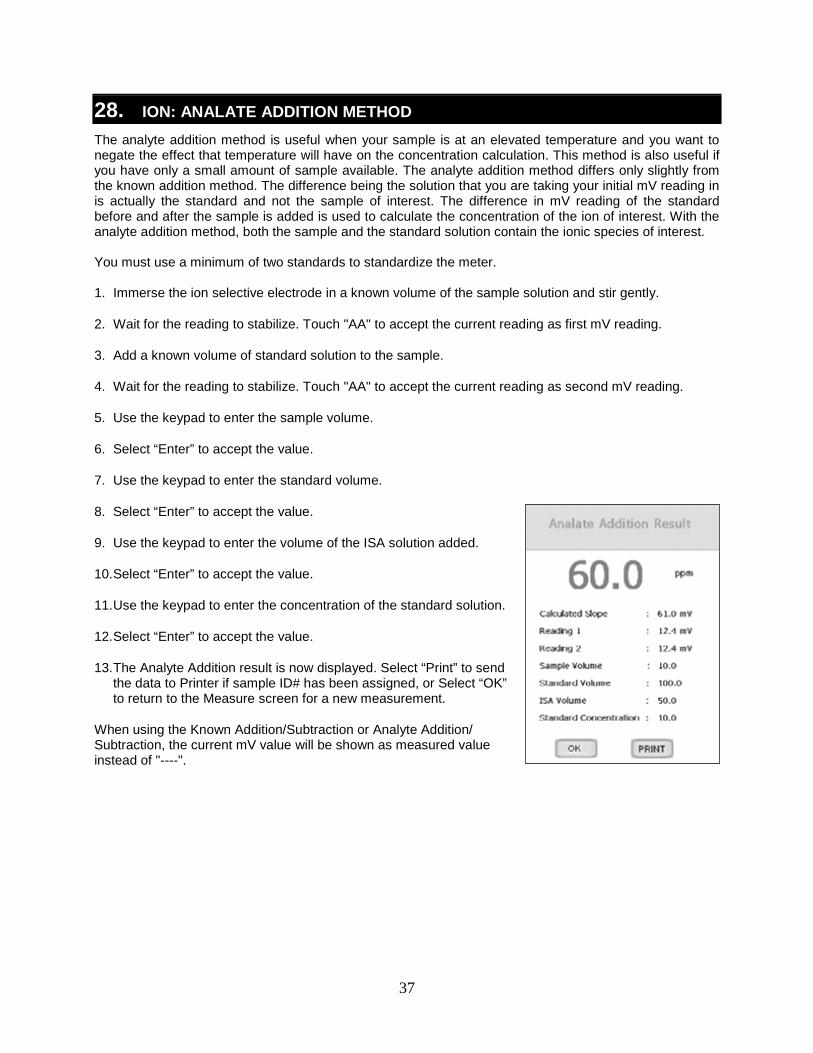
28. ION: ANALATE ADDITION METHOD The analyte addition method is useful when your sample is at an elevated temperature and you want to negate the effect that temperature will have on the concentration calculation. This method is also useful if you have only a small amount of sample available. The analyte addition method differs only slightly from the known addition method. The difference being the solution that you are taking your initial mV reading in is actually the standard and not the sample of interest. The difference in mV reading of the standard before and after the sample is added is used to calculate the concentration of the ion of interest. With the analyte addition method, both the sample and the standard solution contain the ionic species of interest. You must use a minimum of two standards to standardize the meter. 1. Immerse the ion selective electrode in a known volume of the sample solution and stir gently.
2. Wait for the reading to stabilize. Touch "AA" to accept the current reading as first mV reading.
3. Add a known volume of standard solution to the sample.
4. Wait for the reading to stabilize. Touch "AA" to accept the current reading as second mV reading.
5. Use the keypad to enter the sample volume.
6. Select “Enter” to accept the value.
7. Use the keypad to enter the standard volume.
8. Select “Enter” to accept the value.
9. Use the keypad to enter the volume of the ISA solution added.
10. Select “Enter” to accept the value.
11. Use the keypad to enter the concentration of the standard solution.
12. Select “Enter” to accept the value.
13. The Analyte Addition result is now displayed. Select “Print” to send the data to Printer if sample ID# has been assigned, or Select “OK” to return to the Measure screen for a new measurement.
When using the Known Addition/Subtraction or Analyte Addition/ Subtraction, the current mV value will be shown as measured value instead of "----".
38
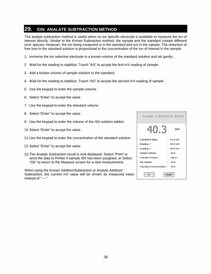
29. ION: ANALATE SUBTRACTION METHOD The analyte subtraction method is useful when no ion specific electrode is available to measure the ion of interest directly. Similar to the Known Subtraction method, the sample and the standard contain different ionic species. However, the ion being measured is in the standard and not in the sample. The reduction of free ions in the standard solution is proportional to the concentration of the ion of interest in the sample. 1. Immerse the ion selective electrode in a known volume of the standard solution and stir gently.
2. Wait for the reading to stabilize. Touch "AS" to accept the first mV reading of sample.
3. Add a known volume of sample solution to the standard.
4. Wait for the reading to stabilize. Touch "AS" to accept the second mV reading of sample.
5. Use the keypad to enter the sample volume.
6. Select “Enter” to accept the value.
7. Use the keypad to enter the standard volume.
8. Select “Enter” to accept the value.
9. Use the keypad to enter the volume of the ISA solution added.
10. Select “Enter” to accept the value.
11. Use the keypad to enter the concentration of the standard solution.
12. Select “Enter” to accept the value.
13. The Analyte Subtraction result is now displayed. Select “Print” to send the data to Printer if sample ID# has been assigned, or Select “OK” to return to the Measure screen for a new measurement.
When using the Known Addition/Subtraction or Analyte Addition/ Subtraction, the current mV value will be shown as measured value instead of "----".
39
30. CONDUCTIVITY / RESISTIVITY OPERATION
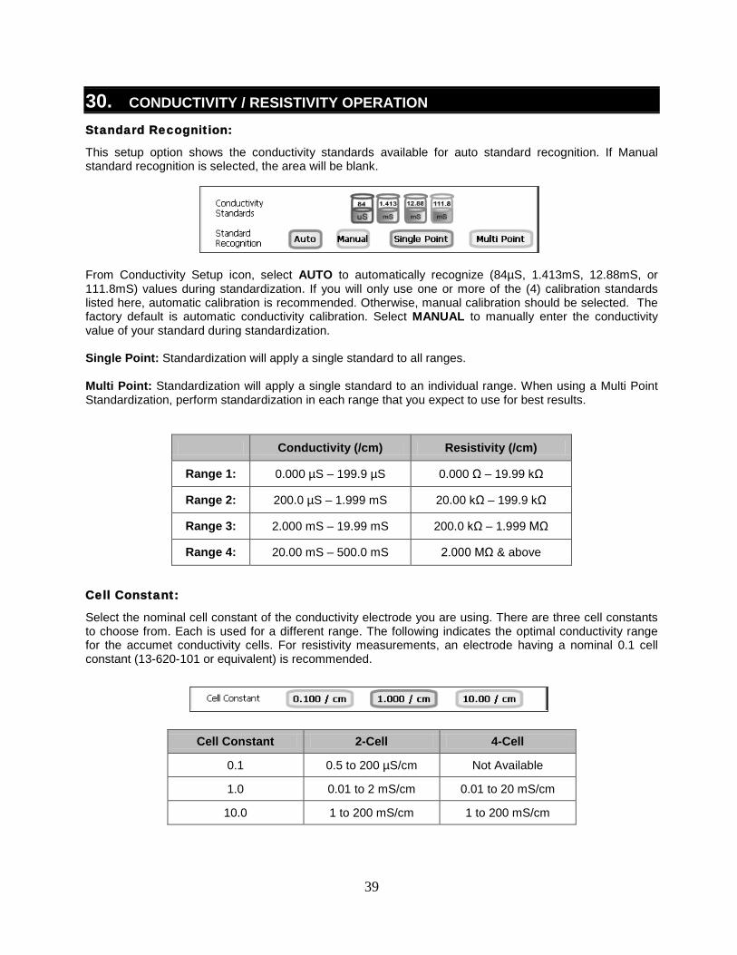
Standard Recognition:
This setup option shows the conductivity standards available for auto standard recognition. If Manual standard recognition is selected, the area will be blank.
From Conductivity Setup icon, select AUTO to automatically recognize (84µS, 1.413mS, 12.88mS, or 111.8mS) values during standardization. If you will only use one or more of the (4) calibration standards listed here, automatic calibration is recommended. Otherwise, manual calibration should be selected. The factory default is automatic conductivity calibration. Select MANUAL to manually enter the conductivity value of your standard during standardization. Single Point: Standardization will apply a single standard to all ranges. Multi Point: Standardization will apply a single standard to an individual range. When using a Multi Point Standardization, perform standardization in each range that you expect to use for best results.
Conductivity (/cm) Resistivity (/cm)
Range 1: 0.000 µS – 199.9 µS 0.000 Ω – 19.99 kΩ
Range 2: 200.0 µS – 1.999 mS 20.00 kΩ – 199.9 kΩ
Range 3: 2.000 mS – 19.99 mS 200.0 kΩ – 1.999 MΩ
Range 4: 20.00 mS – 500.0 mS 2.000 MΩ & above
Cell Constant:
Select the nominal cell constant of the conductivity electrode you are using. There are three cell constants to choose from. Each is used for a different range. The following indicates the optimal conductivity range for the accumet conductivity cells. For resistivity measurements, an electrode having a nominal 0.1 cell constant (13-620-101 or equivalent) is recommended.
Cell Constant 2-Cell 4-Cell
0.1 0.5 to 200 µS/cm Not Available
1.0 0.01 to 2 mS/cm 0.01 to 20 mS/cm
10.0 1 to 200 mS/cm 1 to 200 mS/cm
40
Tip: For methods that require un-adjusted conductivity measurements, set the temperature coefficient to 0.0%. This will allow
temperature measurement without affect on the conductivity measurement.
Default Temperature:
The accumet conductivity electrodes include a built-in temperature sensor. Should the electrode be removed or in the unlikely event that the temperature portion should fail, the default temperature will be used in its place. The factory default setting is 25 °C / 77 °F. Temperature Coefficient:
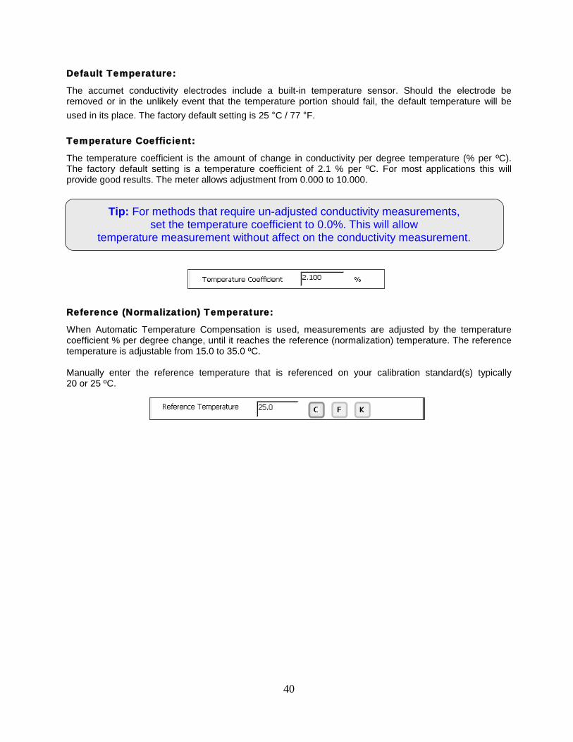
The temperature coefficient is the amount of change in conductivity per degree temperature (% per ºC). The factory default setting is a temperature coefficient of 2.1 % per ºC. For most applications this will provide good results. The meter allows adjustment from 0.000 to 10.000.
Reference (Normalization) Temperature:
When Automatic Temperature Compensation is used, measurements are adjusted by the temperature coefficient % per degree change, until it reaches the reference (normalization) temperature. The reference temperature is adjustable from 15.0 to 35.0 ºC. Manually enter the reference temperature that is referenced on your calibration standard(s) typically 20 or 25 ºC.
41
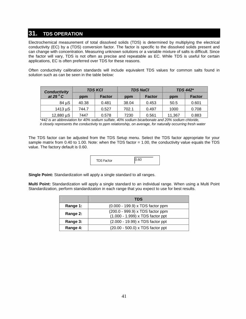
31. TDS OPERATION Electrochemical measurement of total dissolved solids (TDS) is determined by multiplying the electrical conductivity (EC) by a (TDS) conversion factor. The factor is specific to the dissolved solids present and can change with concentration. Measuring unknown solutions or a variable mixture of salts is difficult. Since the factor will vary, TDS is not often as precise and repeatable as EC. While TDS is useful for certain applications, EC is often preferred over TDS for these reasons. Often conductivity calibration standards will include equivalent TDS values for common salts found in solution such as can be seen in the table below:
Conductivity at 25 o C
TDS KCl TDS NaCl TDS 442* ppm Factor ppm Factor ppm Factor
84 µS 40.38 0.481 38.04 0.453 50.5 0.601 1413 µS 744.7 0.527 702.1 0.497 1000 0.708
12,880 µS 7447 0.578 7230 0.561 11,367 0.883 *442 is an abbreviation for 40% sodium sulfate, 40% sodium bicarbonate and 20% sodium chloride, it closely represents the conductivity to ppm relationship, on average, for naturally occurring fresh water
The TDS factor can be adjusted from the TDS Setup menu. Select the TDS factor appropriate for your sample matrix from 0.40 to 1.00. Note: when the TDS factor = 1.00, the conductivity value equals the TDS value. The factory default is 0.60. Single Point: Standardization will apply a single standard to all ranges. Multi Point: Standardization will apply a single standard to an individual range. When using a Multi Point Standardization, perform standardization in each range that you expect to use for best results.
TDS Range 1: (0.000 - 199.9) x TDS factor ppm
Range 2: (200.0 - 999.9) x TDS factor ppm (1.000 - 1.999) x TDS factor ppt
Range 3: (2.000 - 19.99) x TDS factor ppt Range 4: (20.00 - 500.0) x TDS factor ppt
42
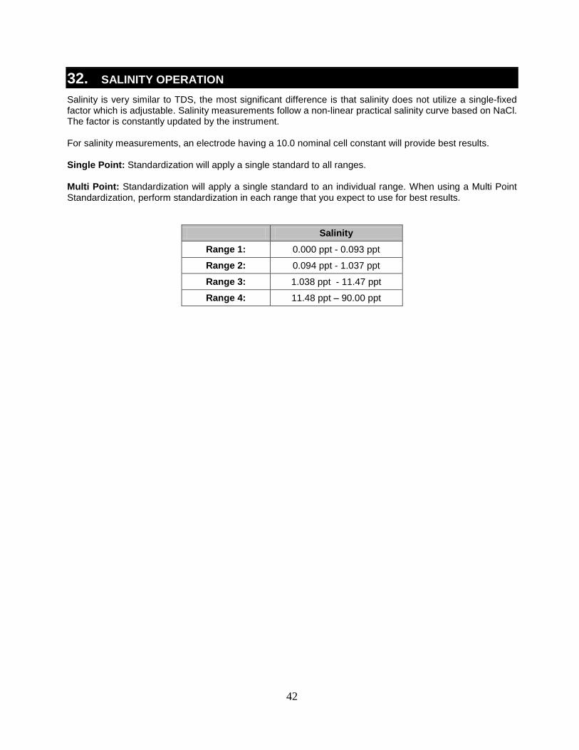
32. SALINITY OPERATION Salinity is very similar to TDS, the most significant difference is that salinity does not utilize a single-fixed factor which is adjustable. Salinity measurements follow a non-linear practical salinity curve based on NaCl. The factor is constantly updated by the instrument. For salinity measurements, an electrode having a 10.0 nominal cell constant will provide best results. Single Point: Standardization will apply a single standard to all ranges. Multi Point: Standardization will apply a single standard to an individual range. When using a Multi Point Standardization, perform standardization in each range that you expect to use for best results.
Salinity Range 1: 0.000 ppt - 0.093 ppt
Range 2: 0.094 ppt - 1.037 ppt
Range 3: 1.038 ppt - 11.47 ppt
Range 4: 11.48 ppt – 90.00 ppt
43
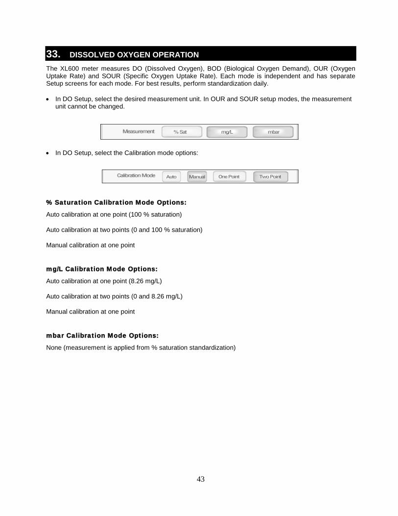
33. DISSOLVED OXYGEN OPERATION The XL600 meter measures DO (Dissolved Oxygen), BOD (Biological Oxygen Demand), OUR (Oxygen Uptake Rate) and SOUR (Specific Oxygen Uptake Rate). Each mode is independent and has separate Setup screens for each mode. For best results, perform standardization daily. • In DO Setup, select the desired measurement unit. In OUR and SOUR setup modes, the measurement
unit cannot be changed.
• In DO Setup, select the Calibration mode options:
% Saturation Calibration Mode Options:
Auto calibration at one point (100 % saturation)
Auto calibration at two points (0 and 100 % saturation)
Manual calibration at one point
mg/L Calibration Mode Options:
Auto calibration at one point (8.26 mg/L)
Auto calibration at two points (0 and 8.26 mg/L)
Manual calibration at one point
mbar Calibration Mode Options:
None (measurement is applied from % saturation standardization)
44
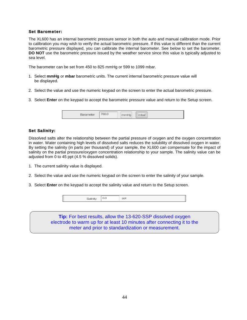
Tip: For best results, allow the 13-620-SSP dissolved oxygen electrode to warm up for at least 10 minutes after connecting it to the
meter and prior to standardization or measurement.
Set Barometer:
The XL600 has an internal barometric pressure sensor in both the auto and manual calibration mode. Prior to calibration you may wish to verify the actual barometric pressure. If this value is different than the current barometric pressure displayed, you can calibrate the internal barometer. See below to set the barometer. DO NOT use the barometric pressure issued by the weather service since this value is typically adjusted to sea level. The barometer can be set from 450 to 825 mmHg or 599 to 1099 mbar. 1. Select mmHg or mbar barometric units. The current internal barometric pressure value will
be displayed.
2. Select the value and use the numeric keypad on the screen to enter the actual barometric pressure.
3. Select Enter on the keypad to accept the barometric pressure value and return to the Setup screen.
Set Salinity:
Dissolved salts alter the relationship between the partial pressure of oxygen and the oxygen concentration in water. Water containing high levels of dissolved salts reduces the solubility of dissolved oxygen in water. By setting the salinity (in parts per thousand) of your sample, the XL600 can compensate for the impact of salinity on the partial pressure/oxygen concentration relationship to your sample. The salinity value can be adjusted from 0 to 45 ppt (4.5 % dissolved solids). 1. The current salinity value is displayed.
2. Select the value and use the numeric keypad on the screen to enter the salinity of your sample.
3. Select Enter on the keypad to accept the salinity value and return to the Setup screen.
45
One Point Automatic Standardization – % Saturation:
A one point automatic standardization for % saturation assumes the dissolved oxygen level is at saturation (100% at 0 ppt salinity, 25.0 °C and 760 mmHg). 1. Power on the XL600, connect the 13-620-SSP probe and allow ≥10 minutes for warm up.
2. Insert DO probe into a BOD bottle filled with 1 inch of water to provide a 100 % relative humidity environment.
3. From DO % saturation measurement screen, select Standardize.
4. The XL600 will automatically recognize the 100 % saturation standardization value, indicated by a blinking 100 % beaker icon. The meter will accept readings that are measured between 30 % and 200 % saturation.
5. When STABLE appears, select Confirm. The meter will return to the measurement screen upon a successful standardization.
Two Point Automatic Standardization – % Saturation:
A two point automatic standardization for % saturation assumes the dissolved oxygen level is at saturation (100 % at 0 ppt salinity, 25.0 °C and 760 mmHg). The XL600 can be standardized at 0 % saturation and 100 % saturation. 0% saturation is required to be the first standardization point, followed by 100 % as the second standardization point. 1. Power on the XL600, connect the 13-620-SSP probe and allow ≥10 minutes for warm up.
2. Insert the 13-620-SSP probe into a “zero oxygen solution” to standardize the 0 %. For best results it is important to allow enough time for the zero oxygen reading to stabilize as low as possible. The value must be
3. From DO % saturation measurement screen, select Standardize.
below 5 % to accept the standardization. TIP: to ensure that the value has leveled off to its lowest point, use the “Show graph” feature.
4. The XL600 will automatically recognize the 0 % saturation standardization value, indicated by a blinking 0 % beaker icon. If 0% is not recognized, check that the standardization mode has been set to “Two Point” in the DO setup menu.
5. When STABLE appears, select Confirm to complete the 0 % standardization.
6. Rinse the 13-620-SSP probe very well to remove any trace of zero oxygen solution. Residual zero oxygen solution will dramatically affect the 100 % standardization if carried over.
7. Insert DO probe into a BOD bottle filled with 1 inch of water to provide a 100 % relative humidity environment.
8. The XL600 will automatically recognize the 100 % saturation standardization value, indicated by a blinking 100 % beaker icon. The meter will accept readings that are measured between 30 % and 200 % saturation.
9. When STABLE appears, select Confirm. The meter will return to the measurement screen upon a successful standardization.
46
One Point Automatic Standardization – mg/L:
A one point automatic standardization for mg/L assumes the dissolved oxygen level is at saturation (8.26 mg/L at 0 ppt salinity, 25.0 °C and 760 mmHg). 1. Power on the XL600, connect the 13-620-SSP probe and allow ≥10 minutes for warm up.
2. Insert DO probe into a BOD bottle filled with 1 inch of water to provide a 100 % relative humidity environment.
3. From DO mg/L measurement screen, select Standardize.
4. The XL600 will automatically recognize the 8.26 mg/L standardization value, indicated by a blinking 8.26 mg/L beaker icon. The meter will accept readings that are measured between ±50 % of the factory default value.
5. When STABLE appears, select Confirm. The meter will return to the measurement screen upon a successful standardization.
Two Point Automatic Standardization – mg/L:
The XL600 can be standardized at 0 mg/L and 8.26 mg/L (at 0 ppt salinity, 25.0 °C and 760 mmHg). 0 mg/L is required to be the first standardization point, followed by 8.26 mg/L as the second standardization point. 1. Power on the XL600, connect the 13-620-SSP probe and allow ≥10 minutes for warm up.
2. Insert the 13-620-SSP probe into a “zero oxygen solution” to standardize the 0 mg/L. For best results it is important to allow enough time for the zero oxygen reading to stabilize as low as possible. The value must be
3. From DO mg/L measurement screen, select Standardize.
below 1 mg/L to accept the standardization. TIP: to ensure that the value has leveled off to its lowest point, use the “Show graph” feature.
4. The XL600 will automatically recognize the 0 mg/L standardization value, indicated by a blinking 0 mg/L beaker icon. If 0 mg/L is not recognized, check that the standardization mode has been set to “Two Point” in the DO setup menu.
5. When STABLE appears, select Confirm to complete the 0 mg/L.
6. Rinse the 13-620-SSP probe very well to remove any trace of zero oxygen solution. Residual zero oxygen solution will dramatically affect the 8.26 mg/L standardization if carried over.
7. Insert DO probe into a BOD bottle filled with 1 inch of water to provide a 100 % relative humidity environment.
8. The XL600 will automatically recognize the 8.26 mg/L standardization value, indicated by a blinking 8.26 mg/L beaker icon. The meter will accept readings that are measured between ±50 % of the factory default value.
9. When STABLE appears, select Confirm. The meter will return to the measurement screen upon a successful standardization.
47
One Point Manual Standardization – mg/L or % Saturation:
A one point automatic standardization for mg/L assumes the dissolved oxygen level is at saturation (8.26 mg/L or 100 % at 0 ppt salinity, 25.0 °C and 760 mmHg). 1. Power on the XL600, connect the 13-620-SSP probe and allow ≥10 minutes for warm up.
2. Insert DO probe into a BOD bottle filled with 1 inch of water to provide a 100 % relative humidity environment.
3. From DO mg/L or % measurement screen, select Standardize.
4. The XL600 will blink a beaker icon without a value before the keypad pops up. Enter the desired mg/L or % value then select Enter.
5. When STABLE appears, select Confirm. The meter will return to the measurement screen upon a successful standardization.
48
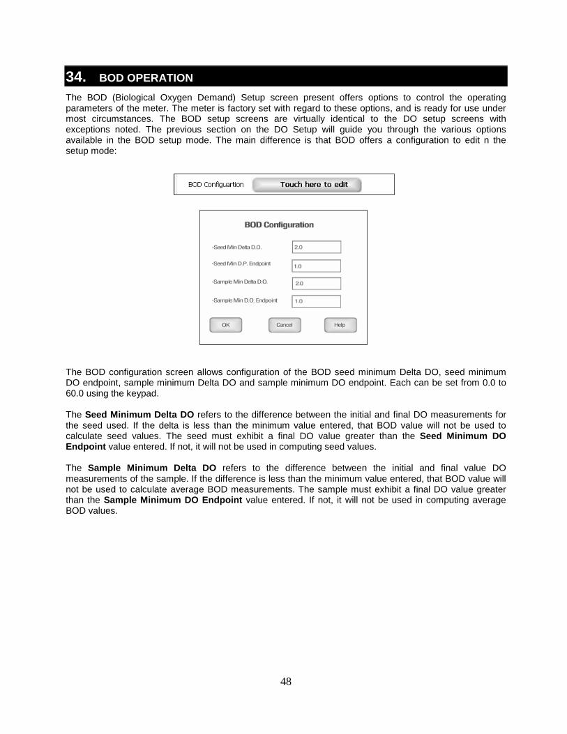
34. BOD OPERATION The BOD (Biological Oxygen Demand) Setup screen present offers options to control the operating parameters of the meter. The meter is factory set with regard to these options, and is ready for use under most circumstances. The BOD setup screens are virtually identical to the DO setup screens with exceptions noted. The previous section on the DO Setup will guide you through the various options available in the BOD setup mode. The main difference is that BOD offers a configuration to edit n the setup mode:
The BOD configuration screen allows configuration of the BOD seed minimum Delta DO, seed minimum DO endpoint, sample minimum Delta DO and sample minimum DO endpoint. Each can be set from 0.0 to 60.0 using the keypad. The Seed Minimum Delta DO refers to the difference between the initial and final DO measurements for the seed used. If the delta is less than the minimum value entered, that BOD value will not be used to calculate seed values. The seed must exhibit a final DO value greater than the Seed Minimum DO Endpoint value entered. If not, it will not be used in computing seed values. The Sample Minimum Delta DO refers to the difference between the initial and final value DO measurements of the sample. If the difference is less than the minimum value entered, that BOD value will not be used to calculate average BOD measurements. The sample must exhibit a final DO value greater than the Sample Minimum DO Endpoint value entered. If not, it will not be used in computing average BOD values.
49
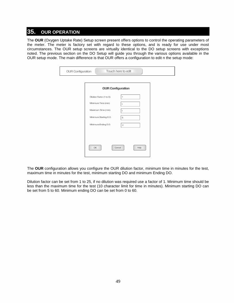
35. OUR OPERATION The OUR (Oxygen Uptake Rate) Setup screen present offers options to control the operating parameters of the meter. The meter is factory set with regard to these options, and is ready for use under most circumstances. The OUR setup screens are virtually identical to the DO setup screens with exceptions noted. The previous section on the DO Setup will guide you through the various options available in the OUR setup mode. The main difference is that OUR offers a configuration to edit n the setup mode:
The OUR configuration allows you configure the OUR dilution factor, minimum time in minutes for the test, maximum time in minutes for the test, minimum starting DO and minimum Ending DO. Dilution factor can be set from 1 to 25, if no dilution was required use a factor of 1. Minimum time should be less than the maximum time for the test (10 character limit for time in minutes). Minimum starting DO can be set from 5 to 60. Minimum ending DO can be set from 0 to 60.
50
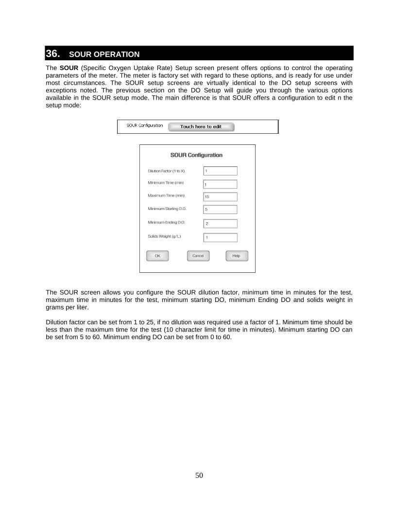
36. SOUR OPERATION The SOUR (Specific Oxygen Uptake Rate) Setup screen present offers options to control the operating parameters of the meter. The meter is factory set with regard to these options, and is ready for use under most circumstances. The SOUR setup screens are virtually identical to the DO setup screens with exceptions noted. The previous section on the DO Setup will guide you through the various options available in the SOUR setup mode. The main difference is that SOUR offers a configuration to edit n the setup mode:
The SOUR screen allows you configure the SOUR dilution factor, minimum time in minutes for the test, maximum time in minutes for the test, minimum starting DO, minimum Ending DO and solids weight in grams per liter. Dilution factor can be set from 1 to 25, if no dilution was required use a factor of 1. Minimum time should be less than the maximum time for the test (10 character limit for time in minutes). Minimum starting DO can be set from 5 to 60. Minimum ending DO can be set from 0 to 60.
Example: - SOUR Setup screen
51
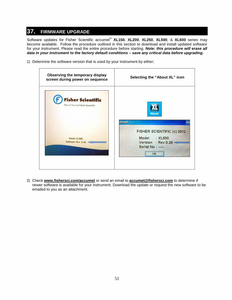
37. FIRMWARE UPGRADE Software updates for Fisher Scientific accumet® XL150, XL200, XL250, XL500, & XL600 series may become available. Follow the procedure outlined in this section to download and install updated software for your instrument. Please read the entire procedure before starting. Note: this procedure will erase all data in your instrument to the factory default conditions – save any critical data before upgrading. 1) Determine the software version that is used by your instrument by either;
Observing the temporary display
screen during power on sequence
Selecting the “About XL” icon
2) Check www.fishersci.com/accumet or send an email to [email protected] to determine if newer software is available for your instrument. Download the update or request the new software to be emailed to you as an attachment.
52
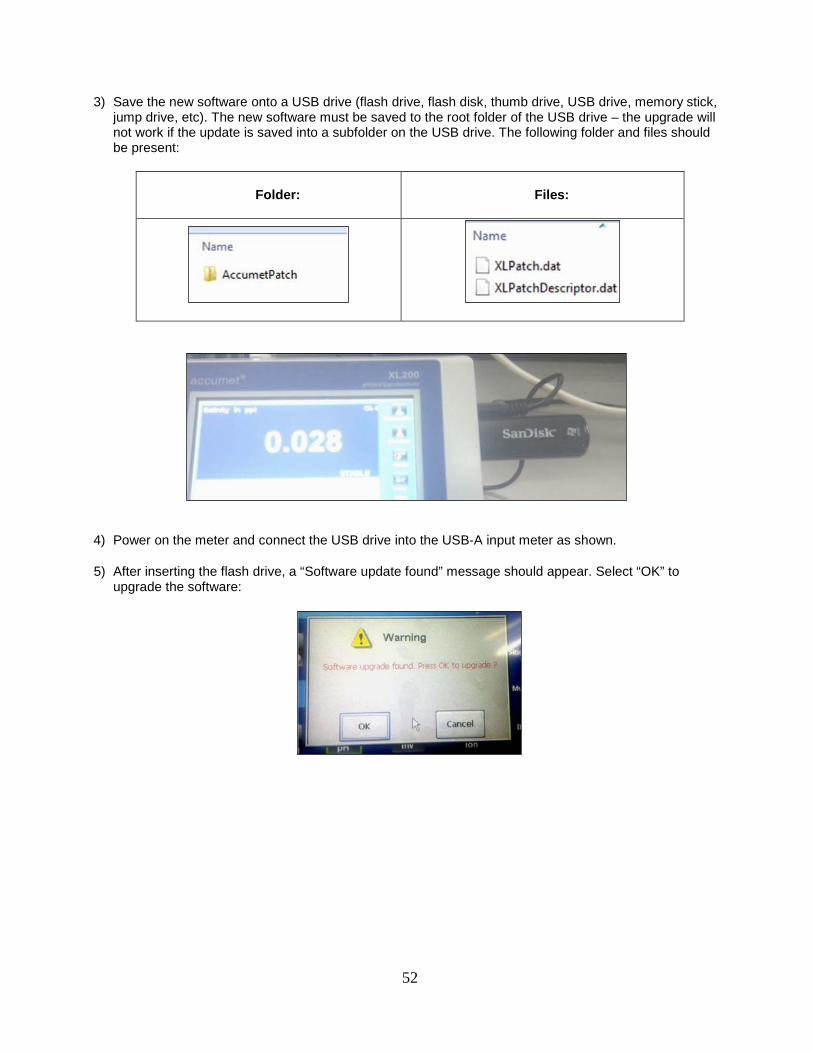
3) Save the new software onto a USB drive (flash drive, flash disk, thumb drive, USB drive, memory stick, jump drive, etc). The new software must be saved to the root folder of the USB drive – the upgrade will not work if the update is saved into a subfolder on the USB drive. The following folder and files should be present:
Folder:
Files:
4) Power on the meter and connect the USB drive into the USB-A input meter as shown.
5) After inserting the flash drive, a “Software update found” message should appear. Select “OK” to upgrade the software:
53
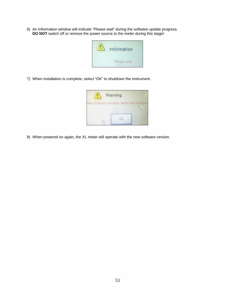
6) An Information window will indicate “Please wait” during the software update progress. DO NOT switch off or remove the power source to the meter during this stage!
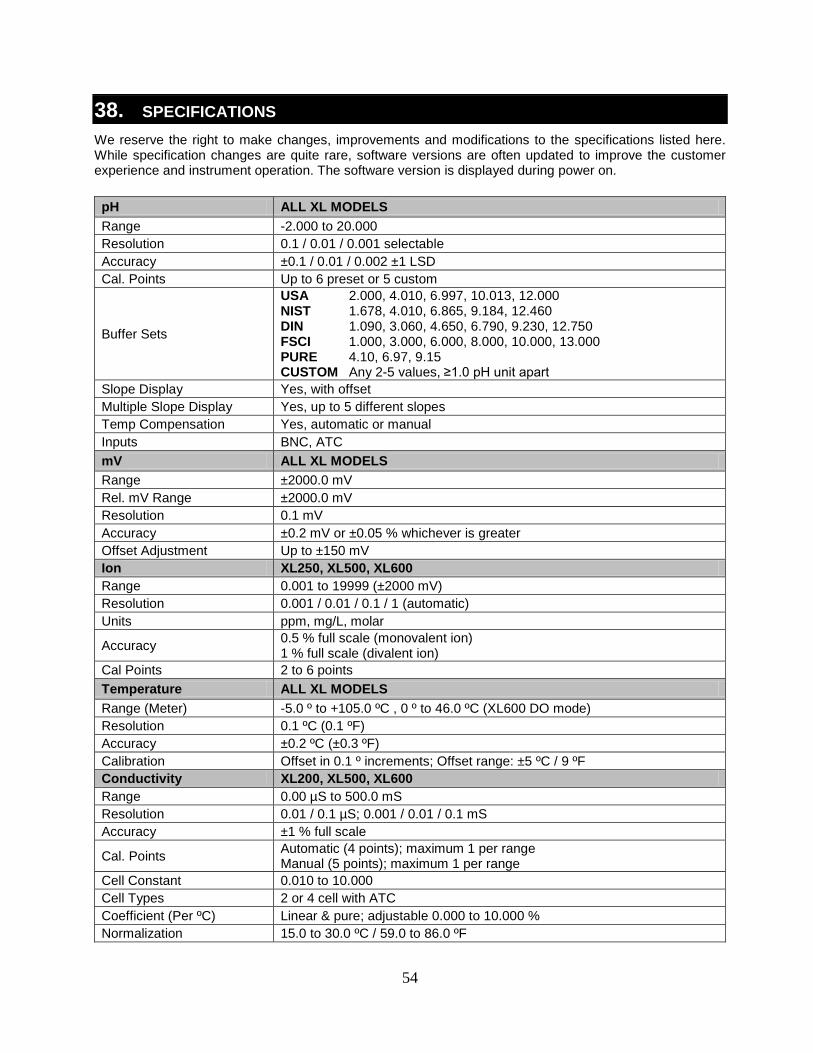
7) When installation is complete, select “OK” to shutdown the instrument.
8) When powered on again, the XL meter will operate with the new software version.
54
38. SPECIFICATIONS We reserve the right to make changes, improvements and modifications to the specifications listed here. While specification changes are quite rare, software versions are often updated to improve the customer experience and instrument operation. The software version is displayed during power on. pH ALL XL MODELS Range -2.000 to 20.000 Resolution 0.1 / 0.01 / 0.001 selectable Accuracy ±0.1 / 0.01 / 0.002 ±1 LSD Cal. Points Up to 6 preset or 5 custom
Buffer Sets
USA 2.000, 4.010, 6.997, 10.013, 12.000 NIST 1.678, 4.010, 6.865, 9.184, 12.460 DIN 1.090, 3.060, 4.650, 6.790, 9.230, 12.750 FSCI 1.000, 3.000, 6.000, 8.000, 10.000, 13.000 PURE 4.10, 6.97, 9.15 CUSTOM Any 2-5 values, ≥1.0 pH unit apart
Slope Display Yes, with offset Multiple Slope Display Yes, up to 5 different slopes Temp Compensation Yes, automatic or manual Inputs BNC, ATC mV ALL XL MODELS Range ±2000.0 mV Rel. mV Range ±2000.0 mV Resolution 0.1 mV Accuracy ±0.2 mV or ±0.05 % whichever is greater Offset Adjustment Up to ±150 mV Ion XL250, XL500, XL600 Range 0.001 to 19999 (±2000 mV) Resolution 0.001 / 0.01 / 0.1 / 1 (automatic) Units ppm, mg/L, molar
Accuracy 0.5 % full scale (monovalent ion) 1 % full scale (divalent ion)
Cal Points 2 to 6 points Temperature ALL XL MODELS Range (Meter) -5.0 º to +105.0 ºC , 0 º to 46.0 ºC (XL600 DO mode) Resolution 0.1 ºC (0.1 ºF) Accuracy ±0.2 ºC (±0.3 ºF) Calibration Offset in 0.1 º increments; Offset range: ±5 ºC / 9 ºF Conductivity XL200, XL500, XL600 Range 0.00 µS to 500.0 mS Resolution 0.01 / 0.1 µS; 0.001 / 0.01 / 0.1 mS Accuracy ±1 % full scale
Cal. Points Automatic (4 points); maximum 1 per range Manual (5 points); maximum 1 per range
Cell Constant 0.010 to 10.000 Cell Types 2 or 4 cell with ATC Coefficient (Per ºC) Linear & pure; adjustable 0.000 to 10.000 % Normalization 15.0 to 30.0 ºC / 59.0 to 86.0 ºF
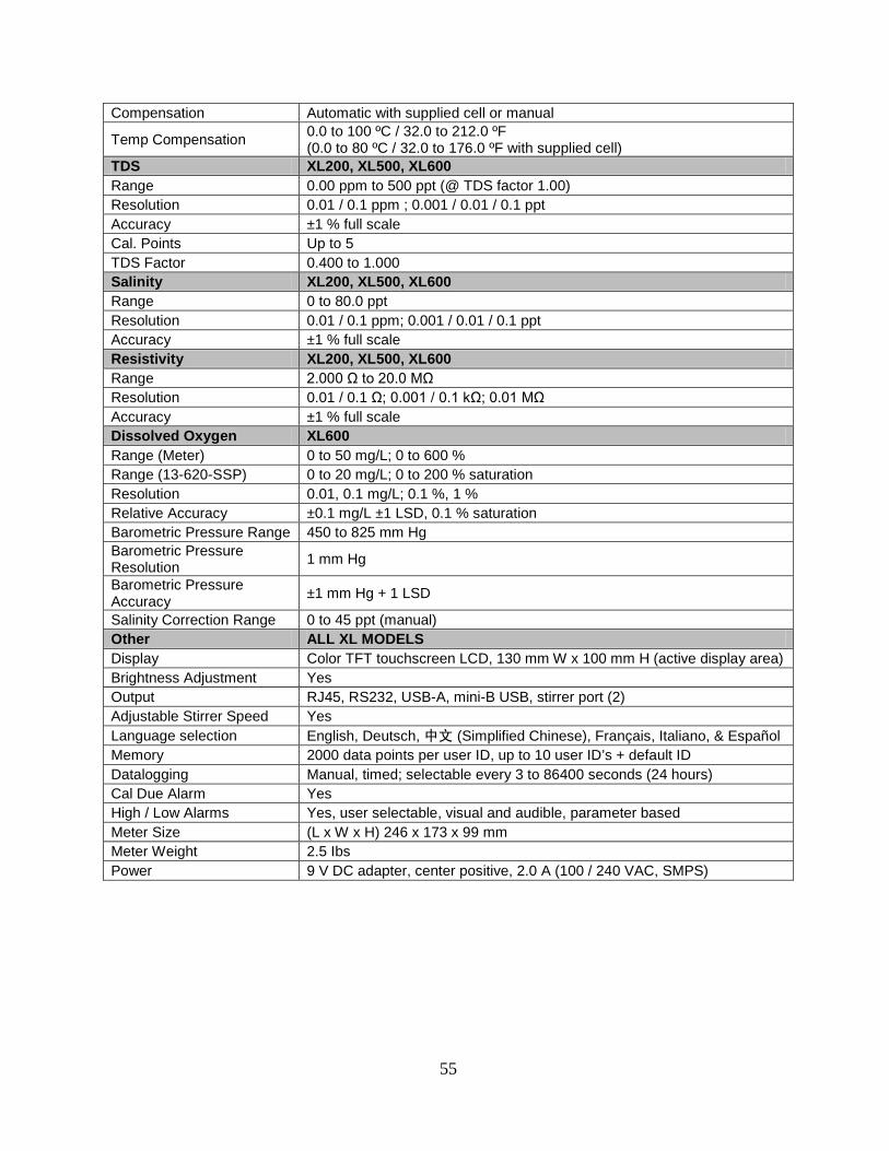
55
Compensation Automatic with supplied cell or manual
Temp Compensation 0.0 to 100 ºC / 32.0 to 212.0 ºF (0.0 to 80 ºC / 32.0 to 176.0 ºF with supplied cell)
TDS XL200, XL500, XL600 Range 0.00 ppm to 500 ppt (@ TDS factor 1.00) Resolution 0.01 / 0.1 ppm ; 0.001 / 0.01 / 0.1 ppt Accuracy ±1 % full scale Cal. Points Up to 5 TDS Factor 0.400 to 1.000 Salinity XL200, XL500, XL600 Range 0 to 80.0 ppt Resolution 0.01 / 0.1 ppm; 0.001 / 0.01 / 0.1 ppt Accuracy ±1 % full scale Resistivity XL200, XL500, XL600 Range 2.000 Ω to 20.0 MΩ Resolution 0.01 / 0.1 Ω; 0.001 / 0.1 kΩ; 0.01 MΩ Accuracy ±1 % full scale Dissolved Oxygen XL600 Range (Meter) 0 to 50 mg/L; 0 to 600 % Range (13-620-SSP) 0 to 20 mg/L; 0 to 200 % saturation Resolution 0.01, 0.1 mg/L; 0.1 %, 1 % Relative Accuracy ±0.1 mg/L ±1 LSD, 0.1 % saturation Barometric Pressure Range 450 to 825 mm Hg Barometric Pressure Resolution 1 mm Hg
Barometric Pressure Accuracy ±1 mm Hg + 1 LSD
Salinity Correction Range 0 to 45 ppt (manual) Other ALL XL MODELS Display Color TFT touchscreen LCD, 130 mm W x 100 mm H (active display area) Brightness Adjustment Yes Output RJ45, RS232, USB-A, mini-B USB, stirrer port (2) Adjustable Stirrer Speed Yes Language selection English, Deutsch, 中文 (Simplified Chinese), Français, Italiano, & Español Memory 2000 data points per user ID, up to 10 user ID’s + default ID Datalogging Manual, timed; selectable every 3 to 86400 seconds (24 hours) Cal Due Alarm Yes High / Low Alarms Yes, user selectable, visual and audible, parameter based Meter Size (L x W x H) 246 x 173 x 99 mm Meter Weight 2.5 Ibs Power 9 V DC adapter, center positive, 2.0 A (100 / 240 VAC, SMPS)
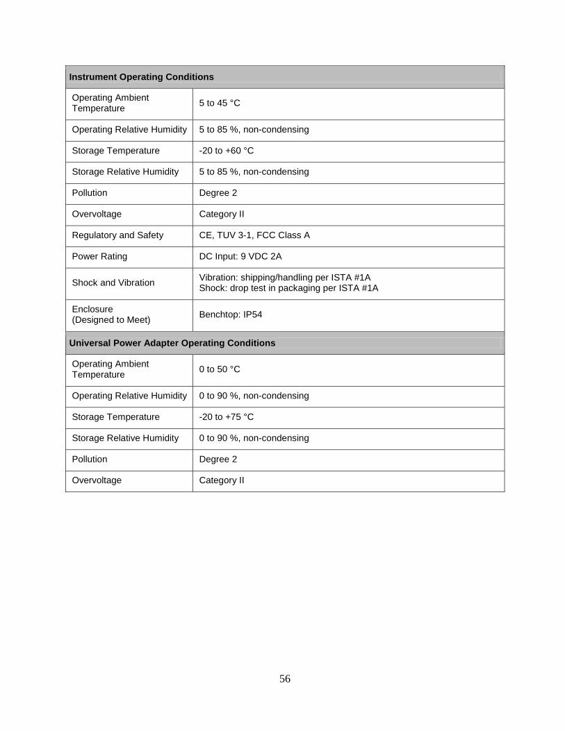
56
Instrument Operating Conditions
Operating Ambient Temperature 5 to 45 °C
Operating Relative Humidity 5 to 85 %, non-condensing
Storage Temperature -20 to +60 °C
Storage Relative Humidity 5 to 85 %, non-condensing
Pollution Degree 2
Overvoltage Category II
Regulatory and Safety CE, TUV 3-1, FCC Class A
Power Rating DC Input: 9 VDC 2A
Shock and Vibration Vibration: shipping/handling per ISTA #1A Shock: drop test in packaging per ISTA #1A
Enclosure (Designed to Meet) Benchtop: IP54
Universal Power Adapter Operating Conditions
Operating Ambient Temperature 0 to 50 °C
Operating Relative Humidity 0 to 90 %, non-condensing
Storage Temperature -20 to +75 °C
Storage Relative Humidity 0 to 90 %, non-condensing
Pollution Degree 2
Overvoltage Category II
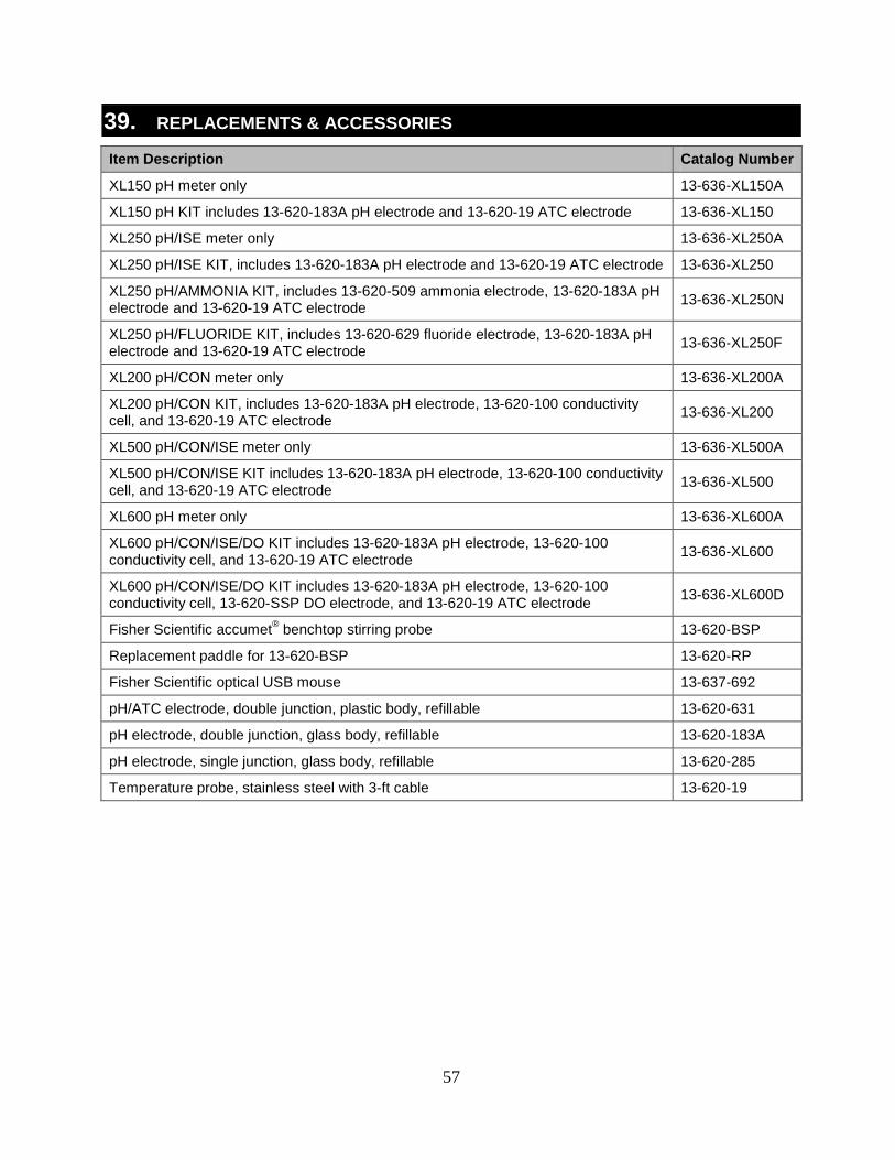
57
39. REPLACEMENTS & ACCESSORIES
Item Description Catalog Number
XL150 pH meter only 13-636-XL150A
XL150 pH KIT includes 13-620-183A pH electrode and 13-620-19 ATC electrode 13-636-XL150
XL250 pH/ISE meter only 13-636-XL250A
XL250 pH/ISE KIT, includes 13-620-183A pH electrode and 13-620-19 ATC electrode 13-636-XL250
XL250 pH/AMMONIA KIT, includes 13-620-509 ammonia electrode, 13-620-183A pH electrode and 13-620-19 ATC electrode 13-636-XL250N
XL250 pH/FLUORIDE KIT, includes 13-620-629 fluoride electrode, 13-620-183A pH electrode and 13-620-19 ATC electrode 13-636-XL250F
XL200 pH/CON meter only 13-636-XL200A
XL200 pH/CON KIT, includes 13-620-183A pH electrode, 13-620-100 conductivity cell, and 13-620-19 ATC electrode 13-636-XL200
XL500 pH/CON/ISE meter only 13-636-XL500A
XL500 pH/CON/ISE KIT includes 13-620-183A pH electrode, 13-620-100 conductivity cell, and 13-620-19 ATC electrode 13-636-XL500
XL600 pH meter only 13-636-XL600A
XL600 pH/CON/ISE/DO KIT includes 13-620-183A pH electrode, 13-620-100 conductivity cell, and 13-620-19 ATC electrode 13-636-XL600
XL600 pH/CON/ISE/DO KIT includes 13-620-183A pH electrode, 13-620-100 conductivity cell, 13-620-SSP DO electrode, and 13-620-19 ATC electrode 13-636-XL600D
Fisher Scientific accumet® benchtop stirring probe 13-620-BSP
Replacement paddle for 13-620-BSP 13-620-RP
Fisher Scientific optical USB mouse 13-637-692
pH/ATC electrode, double junction, plastic body, refillable 13-620-631
pH electrode, double junction, glass body, refillable 13-620-183A
pH electrode, single junction, glass body, refillable 13-620-285
Temperature probe, stainless steel with 3-ft cable 13-620-19
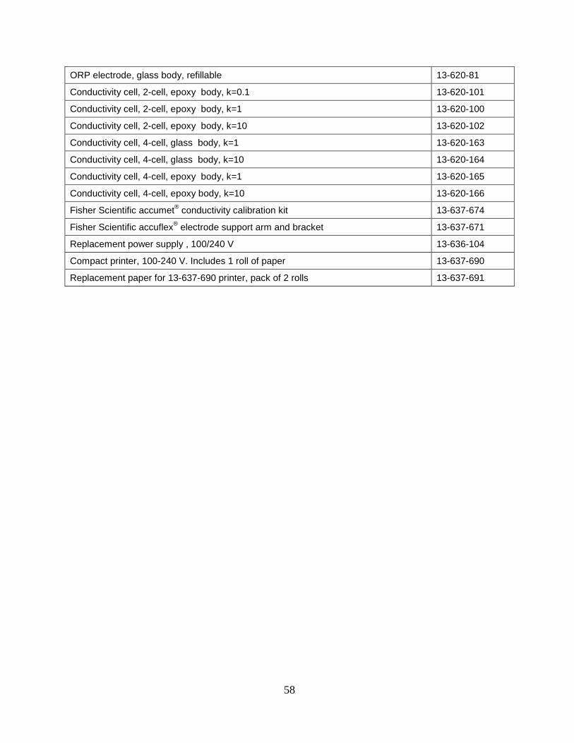
58
ORP electrode, glass body, refillable 13-620-81
Conductivity cell, 2-cell, epoxy body, k=0.1 13-620-101
Conductivity cell, 2-cell, epoxy body, k=1 13-620-100
Conductivity cell, 2-cell, epoxy body, k=10 13-620-102
Conductivity cell, 4-cell, glass body, k=1 13-620-163
Conductivity cell, 4-cell, glass body, k=10 13-620-164
Conductivity cell, 4-cell, epoxy body, k=1 13-620-165
Conductivity cell, 4-cell, epoxy body, k=10 13-620-166
Fisher Scientific accumet® conductivity calibration kit 13-637-674
Fisher Scientific accuflex® electrode support arm and bracket 13-637-671
Replacement power supply , 100/240 V 13-636-104
Compact printer, 100-240 V. Includes 1 roll of paper 13-637-690
Replacement paper for 13-637-690 printer, pack of 2 rolls 13-637-691
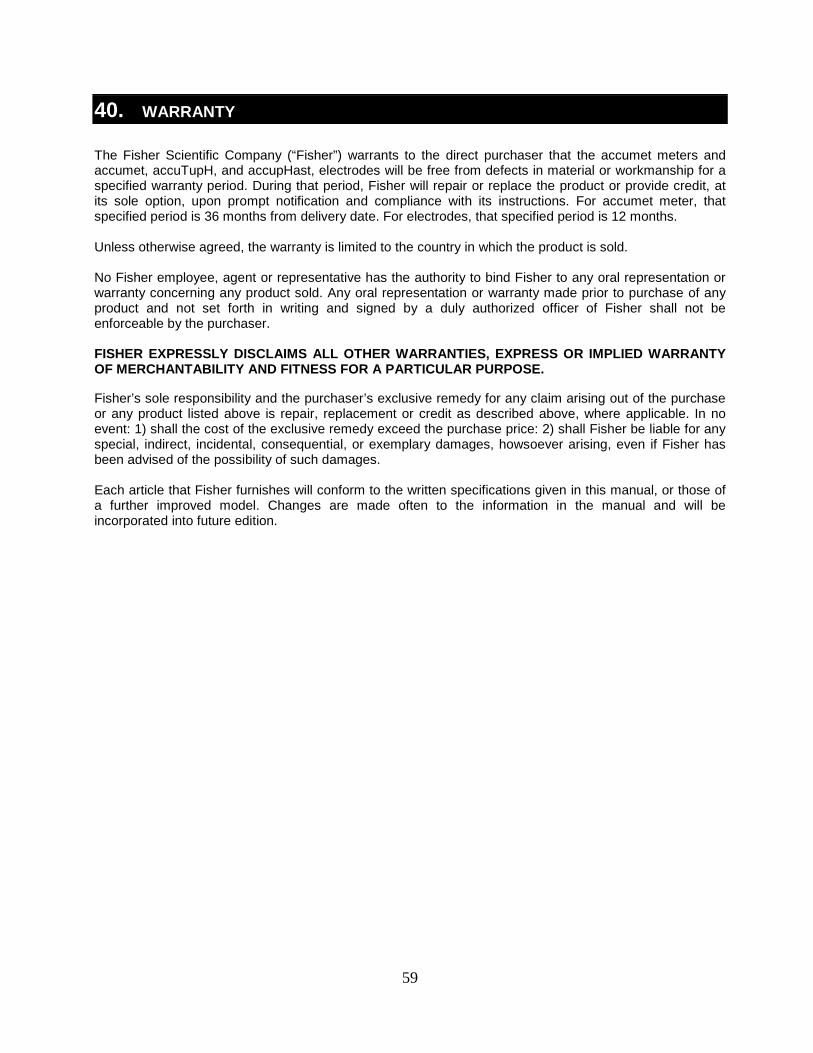
59
40. WARRANTY The Fisher Scientific Company (“Fisher”) warrants to the direct purchaser that the accumet meters and accumet, accuTupH, and accupHast, electrodes will be free from defects in material or workmanship for a specified warranty period. During that period, Fisher will repair or replace the product or provide credit, at its sole option, upon prompt notification and compliance with its instructions. For accumet meter, that specified period is 36 months from delivery date. For electrodes, that specified period is 12 months. Unless otherwise agreed, the warranty is limited to the country in which the product is sold. No Fisher employee, agent or representative has the authority to bind Fisher to any oral representation or warranty concerning any product sold. Any oral representation or warranty made prior to purchase of any product and not set forth in writing and signed by a duly authorized officer of Fisher shall not be enforceable by the purchaser. FISHER EXPRESSLY DISCLAIMS ALL OTHER WARRANTIES, EXPRESS OR IMPLIED WARRANTY OF MERCHANTABILITY AND FITNESS FOR A PARTICULAR PURPOSE.
Fisher’s sole responsibility and the purchaser’s exclusive remedy for any claim arising out of the purchase or any product listed above is repair, replacement or credit as described above, where applicable. In no event: 1) shall the cost of the exclusive remedy exceed the purchase price: 2) shall Fisher be liable for any special, indirect, incidental, consequential, or exemplary damages, howsoever arising, even if Fisher has been advised of the possibility of such damages. Each article that Fisher furnishes will conform to the written specifications given in this manual, or those of a further improved model. Changes are made often to the information in the manual and will be incorporated into future edition.

60
41. RETURN OF ITEMS A “Return Goods Authorization” (RGA) must be obtained from our Customer Service Department or before returning items for any reason. Please include data regarding the reason the items are to be returned. For your protection, items must be carefully packed to prevent damage in shipment and insured against possible damage or loss. We will not be responsible for damage resulting from careless or insufficient packing. A restocking charge will apply to all unauthorized returns.

61
42. NOTICE OF COMPLIANCE This equipment generates, uses, and can radiate radio frequency energy and if not installed and used in accordance with the instruction manual, may cause interference to radio communications. It has been tested and found to comply with the limits for a Class A computing device pursuant to Subpart J of Part 15 of FCC Rules, which are designed to provide reasonable protection against such interference when operated in a commercial environment. Operation of this equipment in a residential area is likely to cause interference in which case the user, at his own expense, will be required to take whatever measures may be required to correct the interference. “This digital apparatus does not exceed the (Class A) limits for radio noise emissions from digital apparatus set out in the Radio Interference Regulations of the Canadian Department of Communications.” “Le present appareil numerique n’ emet pas de bruits radioelectriques depassant les limites applicables aux appareils numeriques (de la class A) prescrites dans le Reglement sur le brouillage radioelectrique edicte par le ministere des Communications du Canada.”
WEEE Compliance: This product is required to comply with the European Union’s Waste Electrical & Electronic Equipment (WEEE) Directive 2002/96/EC. It is marked with the symbol on the left.
Thermo Fisher Scientific has contracted with one or more recycling/disposal companies in each EU Member State and this product should be disposed of or recycled through them. Further information on compliance with these directives, the recyclers in your country, and product information that may assist the detection of substances subject to the RoHS Directive are available from www.thermofisher.com.
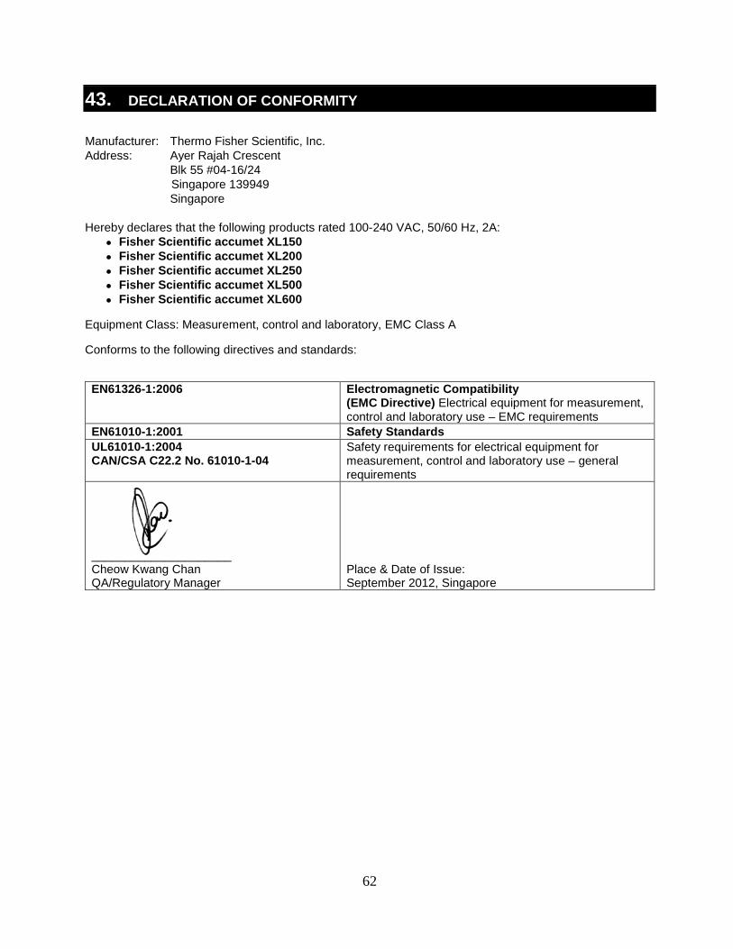
62
43. DECLARATION OF CONFORMITY Manufacturer: Thermo Fisher Scientific, Inc. Address: Ayer Rajah Crescent Blk 55 #04-16/24 Singapore 139949 Singapore Hereby declares that the following products rated 100-240 VAC, 50/60 Hz, 2A:
• Fisher Scientific accumet XL150 • Fisher Scientific accumet XL200 • Fisher Scientific accumet XL250 • Fisher Scientific accumet XL500 • Fisher Scientific accumet XL600
Equipment Class: Measurement, control and laboratory, EMC Class A
Conforms to the following directives and standards:
EN61326-1:2006 Electromagnetic Compatibility
(EMC Directive) Electrical equipment for measurement, control and laboratory use – EMC requirements
EN61010-1:2001 Safety Standards UL61010-1:2004 CAN/CSA C22.2 No. 61010-1-04
Safety requirements for electrical equipment for measurement, control and laboratory use – general requirements
_____________________ Cheow Kwang Chan QA/Regulatory Manager
Place & Date of Issue: September 2012, Singapore
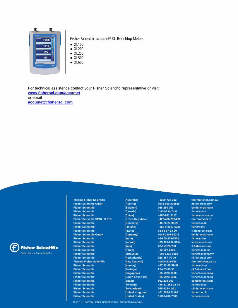
63
For technical assistence contact your Fisher Scientific representative or visit: www.fishersci.com/accumet or email [email protected]
Thermo Fisher Scientific (Australia) +1300-735-292 thermofisher.com.au Fisher Scientific GmbH (Austria) 0043-800-208840 at.fishersci.com Fisher Scientific (Belgium) 056-260-260 be.fishersci.com Fisher Scientific (Canada) 1-800-234-7437 fishersci.ca Fisher Scientific (China) +400-881-5117 fishersci.com.cn Fisher Scientific SPOL. S.R.O. (Czech Republic) +420-466-798-230 thermofisher.cz Fisher Scientific (Denmark) +45-70-27-99-20 fishersci.dk Fisher Scientific (Finland) +358-9-8027-6280 fishersci.fi Fisher Scientific (France) 03-88-67-53-20 fr.fishersci.com Fisher Scientific GmbH (Germany) 0049-2304-932-5 de.fishersci.com Fisher Scientific (India) +1-800-209-7001 fishersci.in Fisher Scientific (Ireland) +35-301-899-5854 ie.fishersci.com Fisher Scientific (Italy) 02-953-28-258 it.fishersci.com Fisher Scientific (Korea) +02-527-0300 fishersci.co.kr Fisher Scientific (Malaysia) +603-5122-8888 fishersci.com.my Fisher Scientific (Netherlands) 020-487-70-00 nl.fishersci.com Thermo Fisher Scientific (New Zealand) +0800-933-966 thermofisher.co.nz Fisher Scientific (Norway) +47-22-95-59-59 fishersci.no Fisher Scientific (Portugal) 21-425-33-50 pt.fishersci.com Fisher Scientific (Singapore) +65-6873-6006 fishersci.com.sg Fisher Scientific (South East Asia) +65-6873-6006 fishersci.com.sg Fisher Scientific (Spain) 902-239-303 es.fishersci.com Fisher Scientific (Sweden) +46-31-352-32-00 fishersci.se Fisher Scientific (Switzerland) 056-618-41-11 ch.fishersci.com Fisher Scientific (United Kingdom) +01-509-231166 fisher.co.uk Fisher Scientific (United States) 1-800-766-7000 fishersci.com
© 2012 Thermo Fisher Scientific Inc. All rights reserved.
Fisher Scientific accumet® XL Benchtop Meters ● XL150 ● XL200 ● XL250 ● XL500 ● XL600